EP3428091B1 - Sortiergerät zum lagerichtigen sortieren von werkstücken - Google Patents
Sortiergerät zum lagerichtigen sortieren von werkstücken Download PDFInfo
- Publication number
- EP3428091B1 EP3428091B1 EP17180746.4A EP17180746A EP3428091B1 EP 3428091 B1 EP3428091 B1 EP 3428091B1 EP 17180746 A EP17180746 A EP 17180746A EP 3428091 B1 EP3428091 B1 EP 3428091B1
- Authority
- EP
- European Patent Office
- Prior art keywords
- container
- sorting device
- slot
- workpieces
- outlet opening
- Prior art date
- Legal status (The legal status is an assumption and is not a legal conclusion. Google has not performed a legal analysis and makes no representation as to the accuracy of the status listed.)
- Active
Links
Images


Classifications
-
- B—PERFORMING OPERATIONS; TRANSPORTING
- B65—CONVEYING; PACKING; STORING; HANDLING THIN OR FILAMENTARY MATERIAL
- B65G—TRANSPORT OR STORAGE DEVICES, e.g. CONVEYORS FOR LOADING OR TIPPING, SHOP CONVEYOR SYSTEMS OR PNEUMATIC TUBE CONVEYORS
- B65G47/00—Article or material-handling devices associated with conveyors; Methods employing such devices
- B65G47/02—Devices for feeding articles or materials to conveyors
- B65G47/04—Devices for feeding articles or materials to conveyors for feeding articles
- B65G47/12—Devices for feeding articles or materials to conveyors for feeding articles from disorderly-arranged article piles or from loose assemblages of articles
- B65G47/14—Devices for feeding articles or materials to conveyors for feeding articles from disorderly-arranged article piles or from loose assemblages of articles arranging or orientating the articles by mechanical or pneumatic means during feeding
- B65G47/1407—Devices for feeding articles or materials to conveyors for feeding articles from disorderly-arranged article piles or from loose assemblages of articles arranging or orientating the articles by mechanical or pneumatic means during feeding the articles being fed from a container, e.g. a bowl
- B65G47/1414—Devices for feeding articles or materials to conveyors for feeding articles from disorderly-arranged article piles or from loose assemblages of articles arranging or orientating the articles by mechanical or pneumatic means during feeding the articles being fed from a container, e.g. a bowl by means of movement of at least the whole wall of the container
-
- B—PERFORMING OPERATIONS; TRANSPORTING
- B23—MACHINE TOOLS; METAL-WORKING NOT OTHERWISE PROVIDED FOR
- B23P—METAL-WORKING NOT OTHERWISE PROVIDED FOR; COMBINED OPERATIONS; UNIVERSAL MACHINE TOOLS
- B23P19/00—Machines for simply fitting together or separating metal parts or objects, or metal and non-metal parts, whether or not involving some deformation; Tools or devices therefor so far as not provided for in other classes
- B23P19/001—Article feeders for assembling machines
- B23P19/002—Article feeders for assembling machines orientating the articles
-
- B—PERFORMING OPERATIONS; TRANSPORTING
- B27—WORKING OR PRESERVING WOOD OR SIMILAR MATERIAL; NAILING OR STAPLING MACHINES IN GENERAL
- B27F—DOVETAILED WORK; TENONS; SLOTTING MACHINES FOR WOOD OR SIMILAR MATERIAL; NAILING OR STAPLING MACHINES
- B27F7/00—Nailing or stapling; Nailed or stapled work
- B27F7/02—Nailing machines
- B27F7/13—Nail feeding devices
Definitions
- the invention relates to a sorting device for sorting workpieces in the correct position with at least one container.
- vibratory feeder pots In particular when very long objects, such as long screws, have to be separated, vibratory feeder pots have to be used which have a very large radius. Such vibratory conveyors are very expensive on the one hand and very large and heavy on the other. If such a vibratory conveyor is to be moved together with a portal, for example, an increased expenditure of energy is necessary.
- US2540934A describes a sorting device according to the preamble of claim 1.
- the object of the present invention is to provide a sorting device with which objects of different sizes can be sorted easily. According to the invention, this object is achieved by a sorting device having the features of claim 1.
- the container of such a sorting device can perform an oscillating movement about the horizontal pivot axis. Due to the oscillating movement, the workpieces to be sorted are always moved from one end of the container to the other and back again. During this movement, some of the workpieces to be separated come into the area of the slot and are lined up there. The workpieces can then leave the container one after the other in the correct orientation through the outlet opening.
- the sorting device according to the invention is suitable for separating workpieces which have a shaft and a head that is larger in cross section than the shaft.
- the slot can be dimensioned so that the width of the slot is slightly larger than the cross section, in particular the diameter, of the shaft, but smaller than the cross section, in particular the diameter, of the head of a workpiece to be separated.
- the shape of the container and / or the orientation of the container to the pivot axis can preferably be selected so that the workpieces are guided to the slot.
- the slot can be provided at the lowest point of the container, so that the workpieces are guided or guided through walls or wall sections of the container to the slot.
- the shape and / or alignment can be selected so that elongated workpieces are aligned in the slot direction.
- the container can be designed, for example, V-, W-, or U-shaped in cross section.
- the container has an edge and / or recess on its underside, in the area of which the slot is arranged.
- the edge and / or the recess can be the deepest point of the container.
- the inner walls of the container extending from the edge or the inner wall sections forming the recess can lead the workpieces to the lowest point of the container and thus to the slot.
- the depression can be trough-shaped.
- the container can be cuboid. One edge of the cuboid can form the lowest point of the container.
- the sorting device can have several containers, in particular several cuboid containers. It is also conceivable that the underside of the sorting device has a plurality of edges or depressions, each of which can have a slot. An exit opening can be provided at the end of each slot.
- the slot advantageously extends approximately perpendicular to the pivot axis. Because of this alignment, the parts to be separated get into the slot more easily.
- a device for adjusting the slot width is provided according to the invention.
- the container can be double-walled in the area of the slot and one of the walls can be adjusted relative to the other wall to enlarge or reduce the slot. In this way it is possible to adjust the slot width to the width of the shaft of the workpieces to be sorted.
- a device for adjusting the size of the outlet opening is provided according to the invention.
- the size of the outlet opening can be adapted to the size of the head of the workpieces to be sorted. In this way it can also be prevented that workpieces to be sorted leave the container through the outlet opening without being suspended in the slot beforehand.
- the pivot axis can be arranged in the area of the outlet opening. This measure makes it particularly easy to ensure a transition of the workpieces to be sorted to a further device, for example a buffer device, without a workpiece falling down.
- the container can have a lid and / or a closable filling opening. This can prevent workpieces to be sorted from falling out of the container during the oscillating movement of the container.
- the wall of the container and / or the lid can be transparent at least in some areas.
- the fill level of the container can be checked by visual inspection.
- the container can be made of transparent plastic at least in some areas.
- the container can be circumferentially closed at least in a rear area. This prevents workpieces to be sorted from falling out of the container when the rear end of the container reaches its lowest point.
- At least one deflection element is provided in the interior of the container. This can have the effect that workpieces to be sorted that are located in the container are not only moved from one end to the other end of the container and back, but that a further movement is also initiated in a ball of workpieces to be sorted. This can cause the workpieces to be sorted in the container to change their orientation, which increases the likelihood of that a shaft of a workpiece to be sorted gets into the slot and the workpiece is then held hanging in the slot by its head.
- the outlet opening can be arranged in the front end region of the container.
- the workpieces can thus leave the container at one end and, for example, be fed to a further guide or buffer device.
- the slot extends over the entire length of the container.
- advantages arise when the slot does not extend over the entire length of the container.
- the slot can extend over about half the length of the container.
- a level sensor in particular an inductive proximity sensor, can be provided in order to monitor the level of the container. This ensures that the container is refilled in good time.
- a retaining element can be provided for retaining workpieces. If there is no retaining element, it could happen that, during a pivoting movement of the container, workpieces to be sorted that are in the container but not yet in the slot overtake the workpieces that are already hanging in the slot and thus prevent the workpieces in the slot hanging workpieces are transported in the direction of the outlet opening. If, however, a retaining element is provided, then with a corresponding pivoting movement of the container, the workpieces hanging in the slot can initially slide in the direction of the outlet opening and then, that is, only when the Container has reached a certain pivoting position, the workpieces still to be sorted can move in the direction of the front end of the container and, if necessary, reach through the slot with their shaft.
- the retaining element can be designed as a ramp or profile.
- the retaining element can be arranged pivotably in or on the container.
- the retaining element can be designed as a type of wall which is pivotably arranged on an inner wall of the container.
- the retaining element can be pivotable against a spring force.
- the spring force can initially hold the retaining element in a retaining position. If the weight of the workpieces becomes too great, the spring force can be overcome so that the retaining element is pivoted away and the workpieces can move unhindered in the container.
- the retaining element can also be designed as a stationary wall, with a free space remaining between the retaining element and the underside of the container through which the workpieces can move.
- a drive can be provided in order to pivot the container about the pivot axis.
- the drive can be an electric or pneumatic drive.
- a buffer section can be connected to the outlet opening.
- the buffer section can have a slot.
- the correctly sorted or aligned workpieces can be transported along the slot, for example to a separating device.
- the inner wall of the container can have a friction-increasing coating or a friction-increasing coating at least in some areas be trained. This ensures that the workpieces can be moved in the container essentially without wear.
- the container can have a damping device in the interior in the area of at least one end face. In this way, the generation of noise during operation of the sorting device can be reduced.
- the container can be formed from a non-magnetic material. This can prevent workpieces to be sorted from sticking to the inner wall of the container and blocking the sorting.
- the Fig. 1 shows a sorting device 1 with a container 2, which is designed in the form of a cuboid in the exemplary embodiment shown.
- the container 2 has an edge 4 on its underside 3.
- a slot 5 is formed in the area of the edge 4.
- the container 2 is pivotably mounted on a frame 7 via a pivot axis 6.
- the container 2 can be set in an oscillating pivoting movement by a drive 8.
- the rear end of the container 2 can be raised so far that the outlet opening 9, which adjoins the slot 5, forms the lowest point of the container 2.
- the size of the outlet opening 9 is set by a device 12.
- the device 12 is designed as a rail with a recess 13. It can be adjusted parallel to the end wall 14 of the container 2 and moved into the area of the outlet opening 9 in order to reduce its cross-sectional size, for example. This can prevent workpieces 10 from passing through the outlet opening 9 without having been arranged in the slot 5 beforehand.
- the container 2 has only one edge 4.
- the underside 3 of the container 2 is designed so that several edges 4 are provided next to one another and accordingly several slots 5.
- several buffer devices 11 can be provided so that faster sorting and feeding of the workpieces 10 for further processing is possible is.
- the pivot axis 6 is arranged in the area of the outlet opening 9 and the outlet opening 9 is provided in the front end area of the container 2. In principle, it would also be conceivable to arrange the pivot axis 6 at a different point on the container 2. It must then be ensured that workpieces 10 which emerge from the outlet opening 9 get into the buffer section 11 without their orientation changing again.
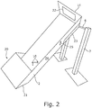
- the Fig. 2 shows a further view of the sorting device 1.
- the container 2 is only closed circumferentially in its rear region 20. This can prevent Workpieces 10, if they are in the rear region 20 of the container 2, cannot leave it.
- deflection elements for example walls that cover the edge 21 in the interior of the container 2, can be arranged in order to make the workpieces 10 change their orientation in the container 2.
- a damping device 22 can be provided on the inside of the end wall 14, by means of which the workpieces 10 are braked and which reduces the generation of noise when the workpieces 10 hit.
- a device 23 is provided according to the invention which is adjustable relative to the wall 24 in order to adjust the width of the slot 5 which is arranged in the area of the device 23.
- the device 23 embodied as a wall can be adjusted in the double arrow direction 25.
- the Fig. 3 shows a variant of the container 2 in a sectional view.
- a retaining element 30 is provided which only releases a through opening 31 in the lower region of the container 2. If the ball of workpieces 10 is accordingly larger than the cross section of the through opening 31, the ball is first braked by the retaining element 30 and only some of the workpieces 10 can pass through the through opening 31.
- the retaining element 30 can be designed as a wall which is oriented transversely to the longitudinal direction of the container 2.
- the Fig. 4 shows a further variation of a container 60 in a side view.
- the container 60 has a recess 61 which has a slot 62 on its underside, which is used for sorting and lining up of workpieces 10 is used.
- a pivot axis 63 is arranged in the area of the front end of the slot 62 and thus in the area of an outlet opening not visible here.
- FIG. 8 shows an end view of a further embodiment of a container 70, which has two depressions on its underside, each with a slot 71, 72.
- the container has a w-shaped section at least in the area of its underside.
Landscapes
- Engineering & Computer Science (AREA)
- Mechanical Engineering (AREA)
- Life Sciences & Earth Sciences (AREA)
- Forests & Forestry (AREA)
- Sorting Of Articles (AREA)
Priority Applications (2)
| Application Number | Priority Date | Filing Date | Title |
|---|---|---|---|
| PL17180746T PL3428091T3 (pl) | 2017-07-11 | 2017-07-11 | Sortownik do prawidłowego ustawiania sortowanych półwyrobów |
| EP17180746.4A EP3428091B1 (de) | 2017-07-11 | 2017-07-11 | Sortiergerät zum lagerichtigen sortieren von werkstücken |
Applications Claiming Priority (1)
| Application Number | Priority Date | Filing Date | Title |
|---|---|---|---|
| EP17180746.4A EP3428091B1 (de) | 2017-07-11 | 2017-07-11 | Sortiergerät zum lagerichtigen sortieren von werkstücken |
Publications (2)
| Publication Number | Publication Date |
|---|---|
| EP3428091A1 EP3428091A1 (de) | 2019-01-16 |
| EP3428091B1 true EP3428091B1 (de) | 2020-09-23 |
Family
ID=59325164
Family Applications (1)
| Application Number | Title | Priority Date | Filing Date |
|---|---|---|---|
| EP17180746.4A Active EP3428091B1 (de) | 2017-07-11 | 2017-07-11 | Sortiergerät zum lagerichtigen sortieren von werkstücken |
Country Status (2)
| Country | Link |
|---|---|
| EP (1) | EP3428091B1 (pl) |
| PL (1) | PL3428091T3 (pl) |
Family Cites Families (11)
| Publication number | Priority date | Publication date | Assignee | Title |
|---|---|---|---|---|
| US2735096A (en) * | 1956-02-21 | miller | ||
| US1546915A (en) * | 1924-02-18 | 1925-07-21 | Bowen Hardware Corp | Automatic feed apparatus for screw blanks |
| US1812501A (en) * | 1929-06-10 | 1931-06-30 | Ferdinand R Strobel | Pin sorter and dispenser |
| US1888520A (en) * | 1931-12-28 | 1932-11-22 | Clara B Parker | Nail gate for nailing machines |
| US2540934A (en) * | 1949-07-15 | 1951-02-06 | Cook & Chick Company | Hopper feed means for fastener driving machines |
| US3106316A (en) * | 1960-10-18 | 1963-10-08 | United Shoe Machinery Corp | Article orienting mechanisms |
| JPS525701B2 (pl) * | 1972-09-11 | 1977-02-16 | ||
| DE2322080C3 (de) * | 1973-05-02 | 1979-03-22 | Sortimat Creuz & Co Gmbh, 7057 Winnenden | Vorrichtung zum ausgerichteten Einbringen von Einwegspritzen in Magazinierkanälen |
| SE429825B (sv) * | 1982-05-28 | 1983-10-03 | Lars Billing | Spikmatningsanordning |
| US5176299A (en) * | 1991-05-23 | 1993-01-05 | Krooss Robert J | Variable volume hopper |
| IT1293292B1 (it) * | 1997-08-04 | 1999-02-16 | Exper S A S Di Peroni Guenther | Dispositivo per l'alimentazione singolarizzata di articoli a sottostanti organi di ricevimento. |
-
2017
- 2017-07-11 PL PL17180746T patent/PL3428091T3/pl unknown
- 2017-07-11 EP EP17180746.4A patent/EP3428091B1/de active Active
Non-Patent Citations (1)
| Title |
|---|
| None * |
Also Published As
| Publication number | Publication date |
|---|---|
| PL3428091T3 (pl) | 2021-04-06 |
| EP3428091A1 (de) | 2019-01-16 |
Similar Documents
| Publication | Publication Date | Title |
|---|---|---|
| DE69001366T2 (de) | Vorrichtung zum Trennen und Ausrichten von Gegenständen und diese Vorrichtung verwendende Sortieranlage. | |
| WO2012059167A1 (de) | Transportvorrichtung zum transportieren von behältern | |
| EP2108603B1 (de) | Versorgungseinheit | |
| WO2016066807A1 (de) | Behälter mit supportring | |
| WO2012100357A1 (de) | Fördereinrichtung für zylindrische körper, mit in förderrichtung geneigten ablaufschienen | |
| EP2937145A1 (de) | Einrichtung zum Fördern eines feinteiligen Mediums | |
| EP3044138B1 (de) | Zellenradbunker zur förderung und vereinzelung von wenigstens einen schaft aufweisenden verbindungselementen | |
| EP3208001B1 (de) | Windsichter mit dreifachtrennung | |
| EP1409385A1 (de) | Luftfförderer | |
| EP3476214A1 (de) | Eierreinigungsvorrichtung sowie verfahren zur reinigung von eiern | |
| DE102007040386B4 (de) | Vorrichtung zur Montage von Kleinteilen mit verbesserter Zufuhreinrichtung | |
| DE19943164A1 (de) | Übergabeeinrichtung für Kleinteile und Transportrinne | |
| DE2015512A1 (de) | Umsetzvorrichtung für Behälter zwischen einem ersten und einem zweiten Förderer | |
| EP4151564A1 (de) | Vibrationswendelförderer und dichtringvereinzelungsbaugruppe | |
| EP3487793A1 (de) | Fördervorrichtung mit einer gezackten schlagleiste | |
| EP1127834A1 (de) | Sortiervorrichtung für becherförmige Gegenstände | |
| DE202013101882U1 (de) | Fördervorrichtung | |
| DE102007062341B3 (de) | Aufstromsichter | |
| EP3428091A1 (de) | Sortiergerät zum lagerichtigen sortieren von werkstücken | |
| CH643097A5 (de) | Vorrichtung zum ablaengen der anschlussdraehte von elektrischen bauelementen. | |
| DE3490473T (de) | Einrichtung zur Orientierung von Stückerzeugnissen in Zuführungseinheiten von Aggregaten | |
| DE3525463C2 (pl) | ||
| DE19830558A1 (de) | Vorrichtung zum Ordnen, Zuführen und Vereinzeln von pilzförmigen Teilen, vorzugsweise von Schrauben | |
| DE102012013993A1 (de) | Vakuum-Gravitations-Sortiervorrichtung | |
| EP2984013B1 (de) | Vorrichtung und verfahren zur dosierung von schüttgutpartikeln |
Legal Events
| Date | Code | Title | Description |
|---|---|---|---|
| PUAI | Public reference made under article 153(3) epc to a published international application that has entered the european phase |
Free format text: ORIGINAL CODE: 0009012 |
|
| STAA | Information on the status of an ep patent application or granted ep patent |
Free format text: STATUS: THE APPLICATION HAS BEEN PUBLISHED |
|
| AK | Designated contracting states |
Kind code of ref document: A1 Designated state(s): AL AT BE BG CH CY CZ DE DK EE ES FI FR GB GR HR HU IE IS IT LI LT LU LV MC MK MT NL NO PL PT RO RS SE SI SK SM TR |
|
| AX | Request for extension of the european patent |
Extension state: BA ME |
|
| STAA | Information on the status of an ep patent application or granted ep patent |
Free format text: STATUS: REQUEST FOR EXAMINATION WAS MADE |
|
| 17P | Request for examination filed |
Effective date: 20190712 |
|
| RBV | Designated contracting states (corrected) |
Designated state(s): AL AT BE BG CH CY CZ DE DK EE ES FI FR GB GR HR HU IE IS IT LI LT LU LV MC MK MT NL NO PL PT RO RS SE SI SK SM TR |
|
| GRAP | Despatch of communication of intention to grant a patent |
Free format text: ORIGINAL CODE: EPIDOSNIGR1 |
|
| STAA | Information on the status of an ep patent application or granted ep patent |
Free format text: STATUS: GRANT OF PATENT IS INTENDED |
|
| RIC1 | Information provided on ipc code assigned before grant |
Ipc: B23P 19/00 20060101ALI20200414BHEP Ipc: B27F 7/13 20060101ALI20200414BHEP Ipc: B65G 47/14 20060101AFI20200414BHEP |
|
| INTG | Intention to grant announced |
Effective date: 20200511 |
|
| GRAS | Grant fee paid |
Free format text: ORIGINAL CODE: EPIDOSNIGR3 |
|
| GRAA | (expected) grant |
Free format text: ORIGINAL CODE: 0009210 |
|
| STAA | Information on the status of an ep patent application or granted ep patent |
Free format text: STATUS: THE PATENT HAS BEEN GRANTED |
|
| AK | Designated contracting states |
Kind code of ref document: B1 Designated state(s): AL AT BE BG CH CY CZ DE DK EE ES FI FR GB GR HR HU IE IS IT LI LT LU LV MC MK MT NL NO PL PT RO RS SE SI SK SM TR |
|
| REG | Reference to a national code |
Ref country code: GB Ref legal event code: FG4D Free format text: NOT ENGLISH |
|
| REG | Reference to a national code |
Ref country code: CH Ref legal event code: EP |
|
| REG | Reference to a national code |
Ref country code: DE Ref legal event code: R096 Ref document number: 502017007372 Country of ref document: DE |
|
| REG | Reference to a national code |
Ref country code: IE Ref legal event code: FG4D Free format text: LANGUAGE OF EP DOCUMENT: GERMAN |
|
| REG | Reference to a national code |
Ref country code: AT Ref legal event code: REF Ref document number: 1316201 Country of ref document: AT Kind code of ref document: T Effective date: 20201015 |
|
| REG | Reference to a national code |
Ref country code: CH Ref legal event code: NV Representative=s name: VALIPAT S.A. C/O BOVARD SA NEUCHATEL, CH |
|
| REG | Reference to a national code |
Ref country code: FI Ref legal event code: FGE |
|
| REG | Reference to a national code |
Ref country code: NL Ref legal event code: FP |
|
| REG | Reference to a national code |
Ref country code: SE Ref legal event code: TRGR |
|
| PG25 | Lapsed in a contracting state [announced via postgrant information from national office to epo] |
Ref country code: NO Free format text: LAPSE BECAUSE OF FAILURE TO SUBMIT A TRANSLATION OF THE DESCRIPTION OR TO PAY THE FEE WITHIN THE PRESCRIBED TIME-LIMIT Effective date: 20201223 Ref country code: GR Free format text: LAPSE BECAUSE OF FAILURE TO SUBMIT A TRANSLATION OF THE DESCRIPTION OR TO PAY THE FEE WITHIN THE PRESCRIBED TIME-LIMIT Effective date: 20201224 Ref country code: BG Free format text: LAPSE BECAUSE OF FAILURE TO SUBMIT A TRANSLATION OF THE DESCRIPTION OR TO PAY THE FEE WITHIN THE PRESCRIBED TIME-LIMIT Effective date: 20201223 Ref country code: HR Free format text: LAPSE BECAUSE OF FAILURE TO SUBMIT A TRANSLATION OF THE DESCRIPTION OR TO PAY THE FEE WITHIN THE PRESCRIBED TIME-LIMIT Effective date: 20200923 |
|
| PG25 | Lapsed in a contracting state [announced via postgrant information from national office to epo] |
Ref country code: LV Free format text: LAPSE BECAUSE OF FAILURE TO SUBMIT A TRANSLATION OF THE DESCRIPTION OR TO PAY THE FEE WITHIN THE PRESCRIBED TIME-LIMIT Effective date: 20200923 Ref country code: RS Free format text: LAPSE BECAUSE OF FAILURE TO SUBMIT A TRANSLATION OF THE DESCRIPTION OR TO PAY THE FEE WITHIN THE PRESCRIBED TIME-LIMIT Effective date: 20200923 |
|
| REG | Reference to a national code |
Ref country code: LT Ref legal event code: MG4D |
|
| PG25 | Lapsed in a contracting state [announced via postgrant information from national office to epo] |
Ref country code: RO Free format text: LAPSE BECAUSE OF FAILURE TO SUBMIT A TRANSLATION OF THE DESCRIPTION OR TO PAY THE FEE WITHIN THE PRESCRIBED TIME-LIMIT Effective date: 20200923 Ref country code: PT Free format text: LAPSE BECAUSE OF FAILURE TO SUBMIT A TRANSLATION OF THE DESCRIPTION OR TO PAY THE FEE WITHIN THE PRESCRIBED TIME-LIMIT Effective date: 20210125 Ref country code: CZ Free format text: LAPSE BECAUSE OF FAILURE TO SUBMIT A TRANSLATION OF THE DESCRIPTION OR TO PAY THE FEE WITHIN THE PRESCRIBED TIME-LIMIT Effective date: 20200923 Ref country code: LT Free format text: LAPSE BECAUSE OF FAILURE TO SUBMIT A TRANSLATION OF THE DESCRIPTION OR TO PAY THE FEE WITHIN THE PRESCRIBED TIME-LIMIT Effective date: 20200923 Ref country code: SM Free format text: LAPSE BECAUSE OF FAILURE TO SUBMIT A TRANSLATION OF THE DESCRIPTION OR TO PAY THE FEE WITHIN THE PRESCRIBED TIME-LIMIT Effective date: 20200923 Ref country code: EE Free format text: LAPSE BECAUSE OF FAILURE TO SUBMIT A TRANSLATION OF THE DESCRIPTION OR TO PAY THE FEE WITHIN THE PRESCRIBED TIME-LIMIT Effective date: 20200923 |
|
| PG25 | Lapsed in a contracting state [announced via postgrant information from national office to epo] |
Ref country code: IS Free format text: LAPSE BECAUSE OF FAILURE TO SUBMIT A TRANSLATION OF THE DESCRIPTION OR TO PAY THE FEE WITHIN THE PRESCRIBED TIME-LIMIT Effective date: 20210123 Ref country code: ES Free format text: LAPSE BECAUSE OF FAILURE TO SUBMIT A TRANSLATION OF THE DESCRIPTION OR TO PAY THE FEE WITHIN THE PRESCRIBED TIME-LIMIT Effective date: 20200923 Ref country code: AL Free format text: LAPSE BECAUSE OF FAILURE TO SUBMIT A TRANSLATION OF THE DESCRIPTION OR TO PAY THE FEE WITHIN THE PRESCRIBED TIME-LIMIT Effective date: 20200923 |
|
| REG | Reference to a national code |
Ref country code: DE Ref legal event code: R097 Ref document number: 502017007372 Country of ref document: DE |
|
| PG25 | Lapsed in a contracting state [announced via postgrant information from national office to epo] |
Ref country code: SK Free format text: LAPSE BECAUSE OF FAILURE TO SUBMIT A TRANSLATION OF THE DESCRIPTION OR TO PAY THE FEE WITHIN THE PRESCRIBED TIME-LIMIT Effective date: 20200923 |
|
| PLBE | No opposition filed within time limit |
Free format text: ORIGINAL CODE: 0009261 |
|
| STAA | Information on the status of an ep patent application or granted ep patent |
Free format text: STATUS: NO OPPOSITION FILED WITHIN TIME LIMIT |
|
| PG25 | Lapsed in a contracting state [announced via postgrant information from national office to epo] |
Ref country code: SI Free format text: LAPSE BECAUSE OF FAILURE TO SUBMIT A TRANSLATION OF THE DESCRIPTION OR TO PAY THE FEE WITHIN THE PRESCRIBED TIME-LIMIT Effective date: 20200923 Ref country code: DK Free format text: LAPSE BECAUSE OF FAILURE TO SUBMIT A TRANSLATION OF THE DESCRIPTION OR TO PAY THE FEE WITHIN THE PRESCRIBED TIME-LIMIT Effective date: 20200923 |
|
| 26N | No opposition filed |
Effective date: 20210624 |
|
| PG25 | Lapsed in a contracting state [announced via postgrant information from national office to epo] |
Ref country code: IT Free format text: LAPSE BECAUSE OF FAILURE TO SUBMIT A TRANSLATION OF THE DESCRIPTION OR TO PAY THE FEE WITHIN THE PRESCRIBED TIME-LIMIT Effective date: 20200923 |
|
| PG25 | Lapsed in a contracting state [announced via postgrant information from national office to epo] |
Ref country code: MC Free format text: LAPSE BECAUSE OF FAILURE TO SUBMIT A TRANSLATION OF THE DESCRIPTION OR TO PAY THE FEE WITHIN THE PRESCRIBED TIME-LIMIT Effective date: 20200923 |
|
| PG25 | Lapsed in a contracting state [announced via postgrant information from national office to epo] |
Ref country code: LU Free format text: LAPSE BECAUSE OF NON-PAYMENT OF DUE FEES Effective date: 20210711 |
|
| PG25 | Lapsed in a contracting state [announced via postgrant information from national office to epo] |
Ref country code: IE Free format text: LAPSE BECAUSE OF NON-PAYMENT OF DUE FEES Effective date: 20210711 |
|
| PG25 | Lapsed in a contracting state [announced via postgrant information from national office to epo] |
Ref country code: CY Free format text: LAPSE BECAUSE OF FAILURE TO SUBMIT A TRANSLATION OF THE DESCRIPTION OR TO PAY THE FEE WITHIN THE PRESCRIBED TIME-LIMIT Effective date: 20200923 |
|
| P01 | Opt-out of the competence of the unified patent court (upc) registered |
Effective date: 20230529 |
|
| PG25 | Lapsed in a contracting state [announced via postgrant information from national office to epo] |
Ref country code: HU Free format text: LAPSE BECAUSE OF FAILURE TO SUBMIT A TRANSLATION OF THE DESCRIPTION OR TO PAY THE FEE WITHIN THE PRESCRIBED TIME-LIMIT; INVALID AB INITIO Effective date: 20170711 |
|
| PG25 | Lapsed in a contracting state [announced via postgrant information from national office to epo] |
Ref country code: MK Free format text: LAPSE BECAUSE OF FAILURE TO SUBMIT A TRANSLATION OF THE DESCRIPTION OR TO PAY THE FEE WITHIN THE PRESCRIBED TIME-LIMIT Effective date: 20200923 |
|
| PG25 | Lapsed in a contracting state [announced via postgrant information from national office to epo] |
Ref country code: MT Free format text: LAPSE BECAUSE OF FAILURE TO SUBMIT A TRANSLATION OF THE DESCRIPTION OR TO PAY THE FEE WITHIN THE PRESCRIBED TIME-LIMIT Effective date: 20200923 |
|
| PGFP | Annual fee paid to national office [announced via postgrant information from national office to epo] |
Ref country code: NL Payment date: 20250721 Year of fee payment: 9 |
|
| PGFP | Annual fee paid to national office [announced via postgrant information from national office to epo] |
Ref country code: FI Payment date: 20250725 Year of fee payment: 9 |
|
| PGFP | Annual fee paid to national office [announced via postgrant information from national office to epo] |
Ref country code: DE Payment date: 20250722 Year of fee payment: 9 |
|
| PGFP | Annual fee paid to national office [announced via postgrant information from national office to epo] |
Ref country code: PL Payment date: 20250704 Year of fee payment: 9 |
|
| PGFP | Annual fee paid to national office [announced via postgrant information from national office to epo] |
Ref country code: BE Payment date: 20250721 Year of fee payment: 9 Ref country code: GB Payment date: 20250722 Year of fee payment: 9 |
|
| PGFP | Annual fee paid to national office [announced via postgrant information from national office to epo] |
Ref country code: FR Payment date: 20250725 Year of fee payment: 9 Ref country code: AT Payment date: 20250722 Year of fee payment: 9 |
|
| PGFP | Annual fee paid to national office [announced via postgrant information from national office to epo] |
Ref country code: CH Payment date: 20250801 Year of fee payment: 9 Ref country code: SE Payment date: 20250722 Year of fee payment: 9 |
|
| PG25 | Lapsed in a contracting state [announced via postgrant information from national office to epo] |
Ref country code: TR Free format text: LAPSE BECAUSE OF FAILURE TO SUBMIT A TRANSLATION OF THE DESCRIPTION OR TO PAY THE FEE WITHIN THE PRESCRIBED TIME-LIMIT Effective date: 20200923 |
|
| REG | Reference to a national code |
Ref country code: CH Ref legal event code: U11 Free format text: ST27 STATUS EVENT CODE: U-0-0-U10-U11 (AS PROVIDED BY THE NATIONAL OFFICE) Effective date: 20260801 |