EP3428041B1 - Colonne de direction multifonctionnelle, véhicule automobile et procédé de fonctionnement d'un véhicule automobile - Google Patents
Colonne de direction multifonctionnelle, véhicule automobile et procédé de fonctionnement d'un véhicule automobile Download PDFInfo
- Publication number
- EP3428041B1 EP3428041B1 EP18179048.6A EP18179048A EP3428041B1 EP 3428041 B1 EP3428041 B1 EP 3428041B1 EP 18179048 A EP18179048 A EP 18179048A EP 3428041 B1 EP3428041 B1 EP 3428041B1
- Authority
- EP
- European Patent Office
- Prior art keywords
- steering
- tube
- motor vehicle
- steering angle
- gear
- Prior art date
- Legal status (The legal status is an assumption and is not a legal conclusion. Google has not performed a legal analysis and makes no representation as to the accuracy of the status listed.)
- Active
Links
- 238000000034 method Methods 0.000 title claims description 24
- 230000008878 coupling Effects 0.000 claims description 46
- 238000010168 coupling process Methods 0.000 claims description 46
- 238000005859 coupling reaction Methods 0.000 claims description 46
- 230000008859 change Effects 0.000 claims description 10
- 238000006073 displacement reaction Methods 0.000 claims description 4
- 230000008901 benefit Effects 0.000 description 10
- 238000001514 detection method Methods 0.000 description 4
- 230000009471 action Effects 0.000 description 2
- 230000005540 biological transmission Effects 0.000 description 2
- 230000033001 locomotion Effects 0.000 description 2
- 230000007935 neutral effect Effects 0.000 description 2
- 208000012886 Vertigo Diseases 0.000 description 1
- 230000003213 activating effect Effects 0.000 description 1
- 230000000712 assembly Effects 0.000 description 1
- 238000000429 assembly Methods 0.000 description 1
- 230000033228 biological regulation Effects 0.000 description 1
- 238000010276 construction Methods 0.000 description 1
- 238000007796 conventional method Methods 0.000 description 1
- 230000007423 decrease Effects 0.000 description 1
- 230000001419 dependent effect Effects 0.000 description 1
- 230000009365 direct transmission Effects 0.000 description 1
- 230000007246 mechanism Effects 0.000 description 1
- 230000001360 synchronised effect Effects 0.000 description 1
Images


Classifications
-
- B—PERFORMING OPERATIONS; TRANSPORTING
- B62—LAND VEHICLES FOR TRAVELLING OTHERWISE THAN ON RAILS
- B62D—MOTOR VEHICLES; TRAILERS
- B62D1/00—Steering controls, i.e. means for initiating a change of direction of the vehicle
- B62D1/02—Steering controls, i.e. means for initiating a change of direction of the vehicle vehicle-mounted
- B62D1/16—Steering columns
- B62D1/18—Steering columns yieldable or adjustable, e.g. tiltable
- B62D1/183—Steering columns yieldable or adjustable, e.g. tiltable adjustable between in-use and out-of-use positions, e.g. to improve access
-
- B—PERFORMING OPERATIONS; TRANSPORTING
- B62—LAND VEHICLES FOR TRAVELLING OTHERWISE THAN ON RAILS
- B62D—MOTOR VEHICLES; TRAILERS
- B62D5/00—Power-assisted or power-driven steering
- B62D5/04—Power-assisted or power-driven steering electrical, e.g. using an electric servo-motor connected to, or forming part of, the steering gear
- B62D5/0457—Power-assisted or power-driven steering electrical, e.g. using an electric servo-motor connected to, or forming part of, the steering gear characterised by control features of the drive means as such
- B62D5/0475—Controlling other elements
- B62D5/0478—Clutches
-
- B—PERFORMING OPERATIONS; TRANSPORTING
- B62—LAND VEHICLES FOR TRAVELLING OTHERWISE THAN ON RAILS
- B62D—MOTOR VEHICLES; TRAILERS
- B62D1/00—Steering controls, i.e. means for initiating a change of direction of the vehicle
- B62D1/02—Steering controls, i.e. means for initiating a change of direction of the vehicle vehicle-mounted
- B62D1/16—Steering columns
- B62D1/166—Means changing the transfer ratio between steering wheel and steering gear
-
- B—PERFORMING OPERATIONS; TRANSPORTING
- B62—LAND VEHICLES FOR TRAVELLING OTHERWISE THAN ON RAILS
- B62D—MOTOR VEHICLES; TRAILERS
- B62D1/00—Steering controls, i.e. means for initiating a change of direction of the vehicle
- B62D1/02—Steering controls, i.e. means for initiating a change of direction of the vehicle vehicle-mounted
- B62D1/16—Steering columns
- B62D1/20—Connecting steering column to steering gear
-
- B—PERFORMING OPERATIONS; TRANSPORTING
- B62—LAND VEHICLES FOR TRAVELLING OTHERWISE THAN ON RAILS
- B62D—MOTOR VEHICLES; TRAILERS
- B62D1/00—Steering controls, i.e. means for initiating a change of direction of the vehicle
- B62D1/24—Steering controls, i.e. means for initiating a change of direction of the vehicle not vehicle-mounted
- B62D1/28—Steering controls, i.e. means for initiating a change of direction of the vehicle not vehicle-mounted non-mechanical, e.g. following a line or other known markers
- B62D1/286—Systems for interrupting non-mechanical steering due to driver intervention
-
- B—PERFORMING OPERATIONS; TRANSPORTING
- B62—LAND VEHICLES FOR TRAVELLING OTHERWISE THAN ON RAILS
- B62D—MOTOR VEHICLES; TRAILERS
- B62D15/00—Steering not otherwise provided for
- B62D15/02—Steering position indicators ; Steering position determination; Steering aids
- B62D15/021—Determination of steering angle
- B62D15/0215—Determination of steering angle by measuring on the steering column
-
- B—PERFORMING OPERATIONS; TRANSPORTING
- B62—LAND VEHICLES FOR TRAVELLING OTHERWISE THAN ON RAILS
- B62D—MOTOR VEHICLES; TRAILERS
- B62D5/00—Power-assisted or power-driven steering
- B62D5/001—Mechanical components or aspects of steer-by-wire systems, not otherwise provided for in this maingroup
- B62D5/003—Backup systems, e.g. for manual steering
-
- B—PERFORMING OPERATIONS; TRANSPORTING
- B62—LAND VEHICLES FOR TRAVELLING OTHERWISE THAN ON RAILS
- B62D—MOTOR VEHICLES; TRAILERS
- B62D5/00—Power-assisted or power-driven steering
- B62D5/001—Mechanical components or aspects of steer-by-wire systems, not otherwise provided for in this maingroup
- B62D5/005—Mechanical components or aspects of steer-by-wire systems, not otherwise provided for in this maingroup means for generating torque on steering wheel or input member, e.g. feedback
- B62D5/006—Mechanical components or aspects of steer-by-wire systems, not otherwise provided for in this maingroup means for generating torque on steering wheel or input member, e.g. feedback power actuated
-
- B—PERFORMING OPERATIONS; TRANSPORTING
- B62—LAND VEHICLES FOR TRAVELLING OTHERWISE THAN ON RAILS
- B62D—MOTOR VEHICLES; TRAILERS
- B62D5/00—Power-assisted or power-driven steering
- B62D5/04—Power-assisted or power-driven steering electrical, e.g. using an electric servo-motor connected to, or forming part of, the steering gear
- B62D5/0457—Power-assisted or power-driven steering electrical, e.g. using an electric servo-motor connected to, or forming part of, the steering gear characterised by control features of the drive means as such
- B62D5/0481—Power-assisted or power-driven steering electrical, e.g. using an electric servo-motor connected to, or forming part of, the steering gear characterised by control features of the drive means as such monitoring the steering system, e.g. failures
Definitions
- the present invention relates to a multifunctional steering column for a motor vehicle.
- the invention also relates to an autonomously drivable motor vehicle with such a steering column and a method for operating such a motor vehicle.
- driver assistance systems are known that the driver of the motor vehicle in certain situations, such as. B. when parking, driving straight ahead, braking or avoiding obstacles.
- Autonomous control systems play a special role among the known driver assistance systems, since they are designed to take over the tasks of the driver for a longer period of time without the driver having to interact.
- the motor vehicle is in compliance with specified legal standards, such as. B. the German road traffic regulations, automatically navigable to a destination.
- a steering wheel assembly for a motor vehicle in which a steering wheel of the steering wheel assembly can be locked against turning by means of a steering wheel locking component. Furthermore, a steering shaft of the steering wheel assembly can be locked against axial displacement by means of a steering shaft locking component. By means of such a steering wheel assembly, the steering wheel can be moved from an operating position into a rest position in which the steering wheel is sunk into an instrument panel, for example.
- the DE 10 2016 110 791 A1 also shows a steering wheel assembly which is designed for an autonomously operable vehicle, in which the steering wheel is designed to be retractable into the instrument panel.
- DE 196 45 504 discloses the preamble of claim 1.
- Known steering wheel assemblies have the disadvantage that coupling the steering wheel to the steering shaft is only possible in a neutral position. Coupling the steering wheel while cornering or changing direction is not possible. This has the disadvantage that switching off the autonomous control system and taking control of the motor vehicle by the driver are only possible under certain conditions and are therefore not possible if these conditions are not met.
- the object of the present invention is to provide a multifunctional steering column for a motor vehicle, a motor vehicle and a method for operating a motor vehicle which do not have or at least partially do not have the disadvantages of the prior art.
- the object of the present invention is to create a multifunctional steering column for a motor vehicle, an autonomously operable motor vehicle with such a steering column and a method for operating such a motor vehicle, which can be switched from autonomous control to in a simple and inexpensive manner improve manual control.
- the object is achieved by a multifunctional steering column for a motor vehicle.
- the steering column has a steering console for connecting the steering column to a body of the motor vehicle, a steering tube with a steering tube axis held on the steering console, a steering wheel connection for mechanically coupling the steering column to a steering wheel and a steering gear end on which a steering gear coupling with a steering gear connection for mechanical coupling with a steering gear of the motor vehicle is arranged on.
- the steering column has a first actuator device for adjusting a first steering angle of the steering wheel connection about the steering tube axis relative to the steering console and a control device for controlling the first actuator device and the steering gear clutch.
- the steering gear coupling is designed to mechanically couple the steering tube to the steering gear of the motor vehicle in a coupling position and to mechanically decouple the lower steering tube from the steering gear of the motor vehicle in a decoupling position.
- the steering column has a first steering angle sensor for detecting the first steering angle of the steering wheel connection about the steering tube axis and a second steering angle sensor for detecting a second steering angle of the steering gear connection about the steering tube axis.
- the control device is designed to control the first actuator device in such a way that the first steering angle is adapted to the second steering angle. Furthermore, the control device is further developed, to adjust the steering gear clutch in the coupling position when the first steering angle corresponds to the second steering angle.
- a multifunctional steering column is understood to mean a steering column which is designed for several different steering modes.
- the steering column thus has several other functions.
- the steering column can be connected, for example screwed, to the body of the motor vehicle by means of the steering console. In this way it can be ensured that the steering tube is held on the body at a defined angle to the body.
- the steering console preferably has an adjustment means for adjusting an angle of inclination of the steering tube to the body.
- the adjusting means can preferably be actuated automatically and more preferably controlled by the control device.
- the adjustment means preferably has a self-locking mechanism, so that when the adjustment means is not activated, the angle of inclination of the steering tube is kept constant.
- the steering tube has the function, for example, of transmitting a first steering angle specified by the driver of the motor vehicle via the steering wheel to a steering gear of the motor vehicle.
- the steering tube can be rotated about the steering tube axis relative to the steering console. A relative rotation of the steering tube to the steering console is determined by the first steering angle. In the case of a steering wheel aligned for straight-ahead travel, the first steering angle is 0 °.
- the steering tube can be mechanically coupled to a steering wheel via the steering wheel connection.
- the steering wheel connection is arranged or formed in a first end of the steering tube and has, for example, a toothing that can be brought into engagement with a corresponding toothing of the steering wheel in order to avoid a relative rotation of the steering wheel to the steering tube and a correct alignment of the steering wheel to facilitate the steering tube when assembling the steering wheel.
- the steering gear end is formed on a second end of the steering tube opposite the steering wheel connection.
- the steering gear coupling is arranged on the steering gear end and, for example, screwed, pressed, clamped, welded or the like to it. A part of the steering gear coupling can also be formed integrally with the steering tube.
- the steering gear connection of the steering gear coupling is arranged on a side of the steering gear coupling pointing away from the steering tube.
- the steering gear connection can be rotated by the second steering angle relative to the steering console.
- the second steering angle is preferably proportional to a steering position of the wheels of the motor vehicle.
- the steering gear connection In the coupling position, the steering gear connection is mechanically coupled to the steering tube in a rotationally fixed manner.
- the coupling position is provided for emergency operation of the steering column, in which a steering angle can be transmitted from the steering wheel via the steering tube directly to the steering gear.
- the first steering angle corresponds to the second steering angle.
- the steering gear connection and the steering tube can be rotated relative to one another.
- the decoupling position is provided for normal operation of the motor vehicle, with normal operation having two operating modes, namely a steer by wire operating mode, i.e. an operating mode in which a first steering angle specified by means of the steering wheel is transmitted to the steering gear in a mechanically decoupled manner, and the autonomous operating mode in which the steering wheel is completely decoupled from the steering gear and the first steering angle is irrelevant for controlling the motor vehicle.
- a steer by wire operating mode i.e. an operating mode in which a first steering angle specified by means of the steering wheel is transmitted to the steering gear in a mechanically decoupled manner
- the autonomous operating mode in which the steering wheel is completely decoupled from the steering gear and the first steering angle is irrelevant for controlling the motor vehicle.
- the steer by wire operating mode it can be provided that the first steering angle corresponds to the second steering angle.
- a change direction of the first steering angle preferably corresponds to the change direction of the second steering angle, so that the first steering angle and the second steering angle differ by a positive factor different from 1.
- an adjustment of the first steering angle can bring about a smaller or larger adjustment of the second steering angle, for example.
- the distinguishing factor can preferably be determined as a function of a vehicle speed, so that as the speed increases, an adjustment of the first steering angle results in a smaller adjustment of the second steering angle.
- the first actuator device is designed to rotate the steering tube about the steering tube axis and thus to adjust the first steering angle.
- a force feedback in the steer by wire operating mode can be transmitted to the steering tube and thus the steering wheel by means of the first actuator device.
- the intensity of these transmitted forces is less than those forces which would actually have been transmitted in the case of a rigid mechanical coupling of the steering gear and the steering tube. In this way, excessive stress on the driver is avoided and driving comfort is increased.
- the first actuator device it is possible to adapt the first steering angle to the second steering angle by rotating the steering tube.
- the first steering angle can be detected by means of the first steering angle sensor and the second steering angle can be detected by means of the second steering angle sensor.
- the control device is designed to control the first actuator device and the steering gear clutch.
- the control device is designed to determine the first steering angle via the first steering angle sensor and the second steering angle via the second steering angle sensor.
- the control device is designed to control or regulate the first actuator device in such a way that the first steering angle is adapted to the second steering angle.
- the control device is designed, the steering gear clutch in the To adjust the coupling position when the first steering angle and the second steering angle correspond to each other.
- the multifunctional steering column according to the invention has the advantage over conventional steering columns that three operating modes can be implemented, namely a steer-by-wire operating mode, an autonomous operating mode and an emergency operating mode.
- the steer-by-wire operating mode force feedback can be simulated on the steering tube via the first actuator device and the control device in order to give the driver a realistic steering feeling, which reflects or at least partially reflects forces acting on the steering system from the road.
- the autonomous operating mode such a mechanical decoupling of the steering tube from the steering gear can be achieved that changing the second steering angle does not change the first steering angle.
- the steering tube and the steering gear connection are mechanically coupled to one another in such a way that a change in the first steering angle causes a corresponding change in the second steering angle.
- the steering column according to the invention has the further advantage that safe switching from the autonomous operating mode to the steer-by-wire operating mode and the emergency operating mode is also possible when the second steering angle is different from 0 °, i.e. the motor vehicle is not driving straight ahead. The driver can therefore safely take control of the motor vehicle even while cornering.
- the first actuator device has a first electric motor and a first planetary gear, the first electric motor being mechanically coupled to the steering tube via the first planetary gear in such a way that the steering tube is rotated by means of the first actuator device the steering tube axis is rotatable.
- the first planetary gear is preferably mechanically coupled to the steering tube via a first belt drive, in particular a toothed belt drive.
- the first actuator device is preferably designed to transmit torques of between 20 and 40 Nm to the steering tube.
- Such a first actuator device has a compact and robust structure and enables the first steering angle to be adjusted quickly. Such a first actuator device is therefore particularly suitable for a steering column.
- the steering tube has an upper steering tube and a lower steering tube, the upper steering tube and the lower steering tube being displaceable relative to one another along the steering tube axis.
- the steering column has a second actuator device for moving the upper steering tube relative to the lower steering tube.
- the control device is designed to control the second actuator device.
- the control device is preferably designed in such a way that the first steering tube and to move the second steering tube together in autonomous driving mode in such a way that the steering wheel can be lowered into an instrument panel of the motor vehicle. It is thus ensured with simple means that the driver receives an enlarged range of motion and thus improved driving comfort.
- a multi-part steering tube can be used to adapt a steering wheel position of the steering wheel to the driver better for the steer by wire operating mode and for the emergency operating mode.
- the second actuator device has a second electric motor, a second planetary gear and a spindle drive, the second electric motor being mechanically coupled to the upper steering tube or the lower steering tube via the second planetary gear and the spindle drive.
- the second planetary gear is preferably mechanically coupled to the spindle drive via a second belt drive, in particular a toothed belt drive.
- Such a second actuator device has a compact and robust construction and enables a quick relative displacement of the upper steering tube and the lower steering tube. Such a second actuator device is therefore particularly suitable for a steering column.
- control device is designed to control the first actuator device when the steering gear clutch is set in the decoupling position such that the first actuator device changes the first steering angle as a function of a change in the second steering angle.
- the steering gear coupling is designed as a magnetic coupling.
- the magnetic coupling is preferably designed to transmit torques of at least 60 to 80 Nm.
- the steering gear clutch is further preferably designed in such a way that the steering gear clutch is automatically brought into the decoupling position when a control current is applied and is automatically brought into the coupling position when the control current is switched off.
- the steering gear clutch can be acted upon with the control current to this in the To keep the decoupled position and thus prevent a direct torque transmission between the steering tube and steering gear.
- it is sufficient to switch off the control current since the steering gear coupling can be automatically brought into the coupling position in this way.
- the steering gear coupling has a spring or the like for providing a restoring force which acts from the decoupling position into the coupling position.
- a steering gear coupling designed in this way has the particular advantage that it is automatically brought into the coupling position in the event of a power failure, so that manual control by the driver in the emergency operating mode is possible.
- the control device is preferably designed to control the first actuator device when the steering gear clutch is set in the coupling position in order to amplify a steering torque introduced via the steering wheel connection.
- a direct torque transmission between the steering tube and the steering gear via the steering gear coupling is possible.
- the control device is designed to detect a steering action by a driver of the motor vehicle introduced via the steering wheel connection and to control the first actuator device in such a way that the first steering angle is changed in the direction of the steering action. In this way, the steering column can be operated with simple means in accordance with a steering column with a steering torque booster.
- the object is achieved by a motor vehicle with a body and a control system for autonomous driving.
- the motor vehicle has a multifunctional steering column according to the first aspect of the invention.
- the steering wheel connection of the steering column is mechanically coupled to a steering wheel of the motor vehicle so that it cannot rotate.
- the steering gear connection is mechanically coupled to a steering gear input of a steering gear of the motor vehicle in order to adjust a steering angle of steerable wheels of the motor vehicle in a torsion-proof manner.
- the control system is designed for autonomous driving of the motor vehicle.
- the control system is preferably designed with a third actuator device for introducing a steering torque into the steering gear or onto a steering axle of the motor vehicle.
- the control system is preferably designed to detect the first steering angle and to control the third actuator device accordingly.
- the control system is coupled to a sensor system of the motor vehicle for detecting the surroundings of the motor vehicle in order to control the third actuator device accordingly in order to avoid collisions with other objects and unintentional departure from the lane.
- the Control system is coupled to a navigation system of the motor vehicle in order to control the third actuator device accordingly from course data of the navigation system and current position data. It is preferred that the control device is designed as part of the control system.
- the motor vehicle described results in all of the advantages that have already been described for the multifunctional steering column according to the first aspect of the invention. Accordingly, the motor vehicle according to the invention has the advantage over conventional motor vehicles that three operating modes can be implemented with simple means and in a cost-effective manner by means of the steering column, namely a steer-by-wire operating mode, an autonomous operating mode and an emergency operating mode.
- a steer-by-wire operating mode force feedback can be simulated on the steering tube via the first actuator device and the control device in order to give the driver a realistic steering feeling, which reflects or at least partially reflects forces acting on the steering system from the road.
- the autonomous operating mode such a mechanical decoupling of the steering tube from the steering gear can be achieved that changing the second steering angle does not change the first steering angle.
- the steering tube and the steering gear connection are mechanically coupled to one another in such a way that a change in the first steering angle causes a corresponding change in the second steering angle.
- the motor vehicle according to the invention has the further advantage that safe switching from the autonomous operating mode to the steer-by-wire operating mode and the emergency operating mode is also possible when the second steering angle is different from 0 °, i.e. the motor vehicle is not driving straight ahead. The driver can therefore safely take control of the motor vehicle even while cornering.
- the steering gear clutch is arranged in the decoupling position, so that a relative rotation of the steering gear connection to the steering tube is possible.
- the motor vehicle is in the autonomous operating mode.
- the second steering angle is adjusted by means of the control system in order to steer the motor vehicle.
- the control system preferably has a third actuator device, which can preferably be controlled by means of the control device. It can be provided according to the invention that the steering wheel in this state is arranged in a retracted state, in particular sunk into an instrument panel of the motor vehicle. In the retracted state, the first steering angle is preferably 0 °.
- the second steering angle is detected by means of the second steering angle sensor.
- the detection of the second steering angle is preferably carried out continuously or is repeated at such a frequency that an actual ACTUAL state of the second steering angle is detected with sufficient precision and up-to-date during operation of the motor vehicle.
- the first steering angle is detected by means of the first steering angle sensor.
- the detection of the first steering angle is preferably carried out continuously or is repeated at such a frequency that an actual ACTUAL state of the first steering angle is detected with sufficient precision and up-to-date during operation of the motor vehicle.
- the first steering angle and the second steering angle are preferably detected simultaneously or substantially simultaneously, so that it is easy to adjust the first steering angle to the second steering angle.
- the steering wheel is automatically adjusted into a steering position by means of the control device and the second actuator device and possibly a further actuator device, in particular for pivoting the steering tube relative to the steering console.
- the steering wheel In the steering position, the steering wheel is arranged for manual use by the driver of the motor vehicle.
- the steering tube is rotated about the steering tube axis by means of the first actuator device controlled by the control device. This turning takes place in such a way that the first steering angle is adapted to the second steering angle until the first steering angle corresponds to the second steering angle.
- the first steering angle is continuously adapted to further changes in the second steering angle.
- the first steering angle preferably corresponds to the second steering angle.
- the first steering angle is in a relationship with the second steering angle that is designed for manual control of the motor vehicle in the respective driving situation. This can therefore mean that the first steering angle is equal to the second steering angle.
- the first steering angle can be multiplied by a positive factor in order to obtain the second steering angle, the factor preferably being speed-dependent in such a way that it decreases with increasing speed.
- the manual operating mode is understood to mean, in particular, the steer-by-wire operating mode.
- the steering tube and the steering gear are coupled to one another in such a way that when the first steering angle is adjusted, the second steering angle is adjustable by means of the third actuator device and when the second steering angle is adjusted, the first steering angle is adjustable by means of the first actuator device.
- This adjustment is preferably carried out by means of the control system.
- switching to the manual operating mode can also take place by adjusting the steering gear clutch into the coupling position, so that the steering tube and the steering gear are mechanically coupled directly to one another.
- the method described yields all the advantages that have already been described for the steering column according to the invention according to the first aspect of the invention and the motor vehicle according to the invention according to the second aspect of the invention. Accordingly, the method according to the invention has the advantage over conventional methods that safe switching from an autonomous operating mode to the steer-by-wire operating mode and the emergency operating mode is also possible with simple means and in a cost-effective manner when the second steering angle is 0 ° is different, so the motor vehicle is not going straight ahead. The driver can therefore safely take control of the motor vehicle even while cornering.
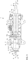
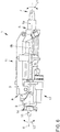
- a preferred embodiment of a multifunctional steering column 1 according to the invention is shown schematically in a plan view from below.
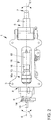
- Fig. 2 shows the same steering column 1 schematically in a plan view from above.
- the steering column 1 has a steering console 3, which is used to connect the steering column 1 to a body 4 of a motor vehicle 2 (cf. Fig. 7 ) is trained.
- a steering tube 5 of the steering column 1 is pivotably held on the steering console 1.
- the steering tube 5 has an upper steering tube 5a and a lower steering tube 5b with a common steering tube axis 6, the upper steering tube 5a being at least partially insertable into the lower steering tube 5b.
- the upper steering tube 5a has a steering wheel connection 7 for connecting a steering wheel, not shown, of the motor vehicle 2.
- the lower steering tube 5b has a steering gear end 8 on which a steering gear coupling 9 designed as a magnetic coupling is arranged.
- the steering gear coupling 9 has a steering gear connection 10 which is designed to connect a steering gear, not shown, of the motor vehicle 2.
- a first actuator device 11 can be seen, which is designed to rotate the steering tube 5 about the steering tube axis 6.
- the first actuator device 11 has a first electric motor 15, which is mechanically coupled to the steering tube 5 in a rotationally synchronous manner via a first planetary gear 16 and a first belt drive 16a.
- a first steering angle sensor 13 for detecting a first steering angle L1 of the steering tube 5 is arranged on the belt drive 16a. In a neutral position, in which the steering tube 5 for a Is arranged to drive straight ahead, the first steering angle L1 is 0 °.
- the first steering angle L1 can be adjusted in a targeted manner by means of the first actuator device 11.
- a second actuator device 17 can be seen, by means of which the upper steering tube 5a can be adjusted relative to the lower steering tube 5b along the steering tube axis 6.
- the second actuator device 17 has a second electric motor 18 which is mechanically coupled to a spindle drive 20 via a second planetary gear 19 and a second belt drive 19a.
- the spindle drive 20 is coupled to the upper steering tube 5a for the axial displacement of the upper steering tube 5a.
- a second steering angle sensor 14 for detecting a second steering angle L2 of the steering gear connection 10 is arranged on the steering gear connection 10.
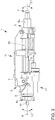
- Fig. 3 the steering column 1 is off Fig. 1 shown schematically in a side view in a retracted position.
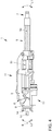
- Fig. 4 shows the steering column 1 in an extended position.
- a substantial portion of the upper steering tube 5a is arranged in the lower steering tube 5b.
- This retracted position can be assumed, for example, in order to lower the steering wheel into an instrument panel of the motor vehicle 2 in order to provide the driver with the greatest possible free space in the autonomous operating mode of the motor vehicle.
- the movement between the retracted and the extended position is possible by means of the second actuator device 17, which is controlled by means of a control device 12 (cf. Fig. 7 ) is controllable.
- the extended position the upper steering tube 5a is maximally extended out of the lower steering tube 5b.
- Fig. 5 shows the steering column off Fig. 1 in an upper position
- Fig. 6 shows the steering column 1 in a lower position.
- the upper steering tube 5 a is pivoted about a pivot axis transversely to the steering tube axis 6 at a maximum towards the steering console 3.
- the upper position is suitable, for example, for particularly tall drivers.
- the lower position the upper steering tube 5a is pivoted away from the steering console 3 at a maximum about the pivot axis transverse to the steering tube axis 6.
- the lower position is suitable, for example, for particularly small drivers.
- the steering column 1 can have a further actuator device, not shown, which preferably has an internal resistance by which it can be ensured that it remains in a selected position when the further actuator device is not activated.
- the further actuator device can preferably be controlled by means of the control device 12.
- a preferred embodiment of a motor vehicle 2 according to the invention is shown schematically in a side view.
- the vehicle 2 has a body 4 and a steering column 1 according to the invention with a control device 12.
- the control device 12 is designed to control mechanical components of the steering column and to evaluate the first steering angle L1 detected by the first steering angle sensor 13 and the second steering angle L2 detected by the second steering angle sensor 14.
- the steering column 1 is fixed to the body 4 via its steering console 3.
- the motor vehicle 2 has a control system 21 for controlling the motor vehicle 2 in an autonomous operating mode.
- the control device 12 is designed as part of the control system 21.
- Fig. 8 shows a preferred embodiment of the method according to the invention in a flow chart.
- a first method step 100 the second steering angle L2 of the steering gear connection 10 is adjusted by means of the control system 21 in the autonomous operating mode of the motor vehicle 2.
- the motor vehicle 2 is thereby steered.
- the second steering angle L2 is detected by means of the second steering angle sensor 14.
- the detection has the advantage that the adjustment of the second steering angle L2 can be carried out particularly precisely in this way.
- the first steering angle L1 is detected by means of the first steering angle sensor 13.
- the detection of the first steering angle L1 and / or the second steering angle L2 is preferably carried out repeatedly or continuously.
- a fourth method step 400 the steering tube 5 is rotated about the steering tube axis 6 by means of the first actuator device 11 controlled by the control device 12 in such a way that the first steering angle L1 corresponds to the second steering angle L2.
- the control system 21 is used to switch to a manual operating mode of the motor vehicle 2. In this state, the second steering angle L2 can be changed by adjusting the first steering angle L1.
Landscapes
- Engineering & Computer Science (AREA)
- Chemical & Material Sciences (AREA)
- Combustion & Propulsion (AREA)
- Transportation (AREA)
- Mechanical Engineering (AREA)
- Steering Control In Accordance With Driving Conditions (AREA)
- Power Steering Mechanism (AREA)
- Steering Controls (AREA)
Claims (9)
- Colonne de direction multifonctionnelle (1) pour un véhicule automobile (2), présentant une console de direction (3) pour la fixation de la colonne de direction (1) sur une carrosserie (4) du véhicule automobile (2), un tube de direction (5) maintenu sur la console de direction (3) comprenant un axe de tube de direction (6), un raccord de volant (7) pour un accouplement mécanique de la colonne de direction (5) avec un volant et une extrémité de mécanisme de direction (8) au niveau de laquelle est disposé un accouplement de mécanisme de direction (9) avec un raccord de mécanisme de direction (10) pour l'accouplement mécanique avec un mécanisme de direction du véhicule automobile (2), un premier dispositif actionneur (11) pour le réglage d'un premier angle de direction (L1) du raccord de volant (7) autour de l'axe de tube de direction (6) par rapport à la console de direction (3) ainsi qu'un dispositif de commande (12) pour la commande du premier dispositif actionneur (11) et de l'accouplement de mécanisme de direction (9), l'accouplement de mécanisme de direction (9) étant formé pour l'accouplement mécanique du tube de direction (5) avec le mécanisme de direction du véhicule automobile (2) dans une position d'accouplement pour un fonctionnement d'urgence et pour le découplage mécanique du tube de direction (5) par rapport au mécanisme de direction du véhicule automobile (2) dans une position de découplage pour un fonctionnement normal, le fonctionnement normal présentant deux modes de fonctionnement, un mode de fonctionnement à commande par câble et un mode de fonctionnement autonome,
caractérisée
en ce que la colonne de direction (1) présente un premier capteur d'angle de direction (13) destiné à détecter le premier angle de direction (L1) du raccord de volant (7) autour de l'axe de tube de direction (6) ainsi qu'un second capteur d'angle de direction (14) destiné à détecter un second angle de direction (L2) du raccord de mécanisme de direction (10) autour de l'axe de tube de direction (6), le dispositif de commande (12) étant conçu pour commander le premier dispositif actionneur (11) de manière à ce que le premier angle de direction (L1) soit ajusté au second angle de direction (L2) et
le dispositif de commande (12) étant en outre conçu pour régler l'accouplement de mécanisme de direction (9) dans la position d'accouplement, lorsque le premier angle de direction (L1) correspond au second angle de direction (L2), une commutation sécurisée du mode de fonctionnement autonome au mode de fonctionnement à commande par câble comme au mode de fonctionnement d'urgence étant également possible lorsque le second angle de direction est différent de 0°,
le tube de direction (5) présentant un tube de direction supérieur (5a) et un tube de direction inférieur (5b), le tube de direction supérieur (5a) et le tube de direction inférieur (5b) pouvant être déplacés l'un par rapport à l'autre le long de l'axe de tube de direction (6), la colonne de direction (1) présentant un second dispositif actionneur (17) pour le déplacement relatif du tube de direction supérieur (5a) par rapport au tube de direction inférieur (5b) et le dispositif de commande (12) étant conçu pour commander le second dispositif actionneur (17). - Colonne de direction (1) selon la revendication 1,
caractérisée
en ce que le premier dispositif actionneur (11) présente un premier moteur électrique (15) et un premier engrenage planétaire (16), le premier moteur électrique (15) étant accouplé mécaniquement au tube de direction (5) par l'intermédiaire du premier engrenage planétaire (16) de telle façon, que le tube de direction (5) peut tourner autour de l'axe de tube de direction (6) au moyen du premier dispositif actionneur (11). - Colonne de direction (1) selon la revendication 2,
caractérisée
en ce que le second dispositif actionneur (17) présente un second moteur électrique (18), un second engrenage planétaire (19) ainsi qu'une transmission à vis (20), le second moteur électrique (18) étant accouplé mécaniquement au tube de direction supérieur (5a) ou au tube de direction inférieur (5b) par l'intermédiaire du second engrenage planétaire (19) et de la transmission à vis (20). - Colonne de direction (1) selon l'une quelconque des revendications précédentes,
caractérisée
en ce que le dispositif de commande (12) est conçu pour commander le premier dispositif actionneur (11) lorsque l'accouplement de mécanisme de direction (9) est dans la position de découplage de telle façon que le premier dispositif actionneur (11) modifie le premier angle de direction (L1) en fonction d'une modification du second angle de direction (L2). - Colonne de direction (1) selon l'une quelconque des revendications précédentes,
caractérisée
en ce que l'accouplement de mécanisme de direction (9) est conçu comme un accouplement magnétique. - Colonne de direction (1) selon la revendication 5,
caractérisée
en ce que l'accouplement de mécanisme de direction (9) est conçu de telle façon que l'accouplement de mécanisme de direction (9) est amené automatiquement dans la position de découplage lors d'une exposition à un courant de commande et dans la position d'accouplement lorsque le courant de commande est coupé. - Colonne de direction (1) selon l'une quelconque des revendications précédentes,
caractérisée
en ce que le dispositif de commande (12) est conçu de façon à commander le premier dispositif actionneur (11), lorsque l'accouplement de mécanisme de direction (9) est réglé dans la position d'accouplement, pour renforcer un couple de direction appliqué par le biais du raccord de volant (7). - Véhicule automobile (2) comprenant une carrosserie (4) et un système de commande (21) pour la conduite autonome,
caractérisé
en ce que le véhicule automobile (2) présente une colonne de direction multifonctionnelle (1) selon l'une quelconque des revendications précédentes. - Procédé destiné à faire fonctionner un véhicule automobile (2) comprenant une colonne de direction multifonctionnelle (1) selon la revendication 8, présentant les étapes suivantes :- réglage du second angle de direction (L2) du raccord de mécanisme de direction (10) au moyen du système de commande (21),- détection du second angle de direction (L2) au moyen du second capteur d'angle de direction (14),- détection du premier angle de direction (L1) au moyen du premier capteur d'angle de direction (13),- rotation du tube de direction (5) autour de l'axe de tube de direction (6) au moyen du premier dispositif actionneur (11) commandé par le dispositif de commande (12) de telle façon que le premier angle de direction (L1) corresponde au second angle de direction (L2),- commutation vers un mode de fonctionnement manuel au moyen du système de commande (21).
Applications Claiming Priority (1)
| Application Number | Priority Date | Filing Date | Title |
|---|---|---|---|
| DE102017211859.8A DE102017211859B4 (de) | 2017-07-11 | 2017-07-11 | Multifunktionale Lenksäule, Kraftfahrzeug und Verfahren zum Betreiben eines Kraftfahrzeugs |
Publications (2)
| Publication Number | Publication Date |
|---|---|
| EP3428041A1 EP3428041A1 (fr) | 2019-01-16 |
| EP3428041B1 true EP3428041B1 (fr) | 2021-05-26 |
Family
ID=62748817
Family Applications (1)
| Application Number | Title | Priority Date | Filing Date |
|---|---|---|---|
| EP18179048.6A Active EP3428041B1 (fr) | 2017-07-11 | 2018-06-21 | Colonne de direction multifonctionnelle, véhicule automobile et procédé de fonctionnement d'un véhicule automobile |
Country Status (4)
| Country | Link |
|---|---|
| US (1) | US11459024B2 (fr) |
| EP (1) | EP3428041B1 (fr) |
| CN (1) | CN109229199A (fr) |
| DE (1) | DE102017211859B4 (fr) |
Families Citing this family (6)
| Publication number | Priority date | Publication date | Assignee | Title |
|---|---|---|---|---|
| KR20210069995A (ko) * | 2019-12-04 | 2021-06-14 | 현대자동차주식회사 | 조향휠 수납장치 및 그 제어방법 |
| CN115667050A (zh) * | 2020-04-20 | 2023-01-31 | 蒂森克虏伯普利斯坦股份公司 | 用于线控转向系统的降级概念 |
| CN114688179B (zh) * | 2020-12-30 | 2023-09-05 | 比亚迪股份有限公司 | 离合装置、车辆转向系统和车辆 |
| CN114684246B (zh) * | 2020-12-30 | 2023-08-08 | 比亚迪股份有限公司 | 车辆转向系统和具有其的车辆 |
| EP4282734A1 (fr) * | 2022-05-23 | 2023-11-29 | Volvo Truck Corporation | Ensemble roue de direction pour un véhicule |
| US11999407B1 (en) | 2023-02-21 | 2024-06-04 | Ford Global Technologies, Llc | Translating steering column with reduced packaging space |
Citations (4)
| Publication number | Priority date | Publication date | Assignee | Title |
|---|---|---|---|---|
| DE10103667A1 (de) * | 2001-01-27 | 2002-08-01 | Bosch Gmbh Robert | Aktuator für eine Steer-by-Wire-Lenkanlage |
| DE10302559A1 (de) * | 2003-01-22 | 2004-09-09 | Daimlerchrysler Ag | Verfahren zur Synchronisation von Lenkhandhabe und gelenkten Fahrzeugrädern |
| DE102007002266A1 (de) * | 2007-01-16 | 2008-07-17 | GM Global Technology Operations, Inc., Detroit | Verfahren zum Betrieb eines Kraftfahrzeugs während eines Fahrmanövers |
| DE102015225888A1 (de) * | 2015-12-18 | 2017-06-22 | Volkswagen Aktiengesellschaft | Verfahren und Vorrichtung zum Anpassen eines Lenkradwinkels eines Lenkrades und eines Radlenkwinkels einer Radlenkung in einem Kraftfahrzeug nach einem durchgeführten automatisierten Fahrmanöver |
Family Cites Families (26)
| Publication number | Priority date | Publication date | Assignee | Title |
|---|---|---|---|---|
| US4415054A (en) * | 1982-08-05 | 1983-11-15 | Trw Inc. | Steering gear |
| US4913249A (en) * | 1986-07-19 | 1990-04-03 | Zahnradfabrik Friedrichshafen, Ag. | Auxiliary power steering mechanism, especially for motor vehicles |
| DE4009400A1 (de) * | 1990-03-23 | 1991-09-26 | Porsche Ag | Aktuator fuer eine kybernetische lenkung |
| JP3097542B2 (ja) * | 1996-02-05 | 2000-10-10 | トヨタ自動車株式会社 | 自動操舵装置 |
| JP3627120B2 (ja) * | 1997-02-19 | 2005-03-09 | 光洋精工株式会社 | 車両用操舵装置 |
| DE19833189A1 (de) * | 1998-07-23 | 2000-01-27 | Bayerische Motoren Werke Ag | Lenksystem für ein Fahrzeug |
| DE19859806B4 (de) * | 1998-12-23 | 2005-03-31 | Daimlerchrysler Ag | Lenksystem für Kraftfahrzeuge |
| JP2004034751A (ja) | 2002-06-28 | 2004-02-05 | Koyo Seiko Co Ltd | 車両用操舵装置 |
| JP4114481B2 (ja) | 2003-01-07 | 2008-07-09 | 日産自動車株式会社 | 車両用操舵制御装置 |
| DE102014200100B4 (de) * | 2013-01-15 | 2018-04-05 | Ford Global Technologies, Llc | Lenkwinkelfehlerkorrektur |
| US9333983B2 (en) | 2013-03-15 | 2016-05-10 | Volkswagen Ag | Dual-state steering wheel/input device |
| JP5835275B2 (ja) | 2013-06-19 | 2015-12-24 | トヨタ自動車株式会社 | 車両の操舵装置 |
| US9199667B2 (en) * | 2014-03-14 | 2015-12-01 | Mitsubishi Electric Research Laboratories, Inc. | System and method for semi-autonomous driving of vehicles |
| DE102014117718A1 (de) * | 2014-12-02 | 2016-06-02 | Trw Automotive Gmbh | Lenkvorrichtung sowie Verfahren zur Steuerung einer Lenkvorrichtung |
| EP3042825B1 (fr) | 2015-01-12 | 2022-03-09 | Volvo Car Corporation | Ensemble de volant de direction pour la rétraction d'un volant de direction dans un véhicule |
| JP2016159895A (ja) | 2015-03-05 | 2016-09-05 | 株式会社ショーワ | 反力アクチュエータ及び操舵装置 |
| JP6521302B2 (ja) * | 2015-04-13 | 2019-05-29 | 株式会社ジェイテクト | 車両用操舵装置 |
| US9919724B2 (en) * | 2015-05-29 | 2018-03-20 | Steering Solutions Ip Holding Corporation | Retractable steering column with manual retrieval |
| DE102015007280A1 (de) * | 2015-06-10 | 2016-12-15 | Thyssenkrupp Ag | Fahrzeuglenkung mit Steer-by-Wire-System und mechanischer Rückfallebene |
| DE102016110791A1 (de) * | 2015-06-15 | 2016-12-15 | Steering Solutions Ip Holding Corporation | Gestensteuerung für ein einfahrbares Lenkrad |
| DE102016111473A1 (de) * | 2015-06-25 | 2016-12-29 | Steering Solutions Ip Holding Corporation | Stationäre lenkradbaugruppe und verfahren |
| US9845103B2 (en) * | 2015-06-29 | 2017-12-19 | Steering Solutions Ip Holding Corporation | Steering arrangement |
| US9849904B2 (en) | 2015-07-31 | 2017-12-26 | Steering Solutions Ip Holding Corporation | Retractable steering column with dual actuators |
| DE102015224602B4 (de) * | 2015-12-08 | 2023-05-04 | Thyssenkrupp Ag | Lenksäule für eine steer-by-wire-Lenkeinrichtung |
| CN206012708U (zh) | 2016-09-12 | 2017-03-15 | 西安科技大学 | 煤矿井下无人驾驶车辆用转向装置 |
| US10160473B2 (en) * | 2016-09-13 | 2018-12-25 | Steering Solutions Ip Holding Corporation | Steering column decoupling system |
-
2017
- 2017-07-11 DE DE102017211859.8A patent/DE102017211859B4/de active Active
-
2018
- 2018-06-21 EP EP18179048.6A patent/EP3428041B1/fr active Active
- 2018-07-06 US US16/028,661 patent/US11459024B2/en active Active
- 2018-07-11 CN CN201810758588.5A patent/CN109229199A/zh active Pending
Patent Citations (4)
| Publication number | Priority date | Publication date | Assignee | Title |
|---|---|---|---|---|
| DE10103667A1 (de) * | 2001-01-27 | 2002-08-01 | Bosch Gmbh Robert | Aktuator für eine Steer-by-Wire-Lenkanlage |
| DE10302559A1 (de) * | 2003-01-22 | 2004-09-09 | Daimlerchrysler Ag | Verfahren zur Synchronisation von Lenkhandhabe und gelenkten Fahrzeugrädern |
| DE102007002266A1 (de) * | 2007-01-16 | 2008-07-17 | GM Global Technology Operations, Inc., Detroit | Verfahren zum Betrieb eines Kraftfahrzeugs während eines Fahrmanövers |
| DE102015225888A1 (de) * | 2015-12-18 | 2017-06-22 | Volkswagen Aktiengesellschaft | Verfahren und Vorrichtung zum Anpassen eines Lenkradwinkels eines Lenkrades und eines Radlenkwinkels einer Radlenkung in einem Kraftfahrzeug nach einem durchgeführten automatisierten Fahrmanöver |
Also Published As
| Publication number | Publication date |
|---|---|
| EP3428041A1 (fr) | 2019-01-16 |
| DE102017211859A1 (de) | 2019-01-17 |
| DE102017211859B4 (de) | 2021-04-22 |
| US11459024B2 (en) | 2022-10-04 |
| CN109229199A (zh) | 2019-01-18 |
| US20190016376A1 (en) | 2019-01-17 |
Similar Documents
| Publication | Publication Date | Title |
|---|---|---|
| EP3428041B1 (fr) | Colonne de direction multifonctionnelle, véhicule automobile et procédé de fonctionnement d'un véhicule automobile | |
| EP3122613B1 (fr) | Système de direction | |
| DE102006048947B4 (de) | Steuereinheit und Verfahren zum Verstellen eines an ein Fahrzeug angekuppelten Anhängers | |
| EP2460712B1 (fr) | Procédé de fonctionnement d'un véhicule automobile et véhicule automobile doté d'un dispositif de détection d'environnement | |
| EP3458336B1 (fr) | Système de direction à commande par câble avec des directions de roue individuellement couplable | |
| EP3746335B1 (fr) | Procédé de protection des occupants d'un véhicule automobile équipé d'un système de direction steer-by-wire | |
| DE102016115466B4 (de) | Steuerhorn für die Lenkung eines Kraftfahrzeugs | |
| DE19831071C2 (de) | Lenksystem für Kraftfahrzeuge | |
| DE102017204830A1 (de) | Verfahren und Fahrerassistenzsystem zur Unterstützung des Ein- und/oder Ausparkens eines Kraftfahrzeugs | |
| EP3814198A1 (fr) | Système de direction à commande électrique à caractéristiques de démultiplication de direction adaptée à la situation de direction | |
| EP1904358A1 (fr) | Systeme de direction pour une direction a superposition | |
| WO2017198565A1 (fr) | Système à commande électrique « steer-by-wire », véhicule automobile et procédé de fonctionnement d'un système à commande électrique « steer-by-wire » | |
| DE102019202003A1 (de) | Verfahren zur Steuerung eines Lenksystems für ein Kraftfahrzeug und Lenksystem für ein Kraftfahrzeug zur Durchführung des Verfahrens | |
| EP2497658A1 (fr) | Véhicule de traction doté d'une remorque | |
| WO2015055363A1 (fr) | Dispositif d'angle de braquage pour un véhicule automobile | |
| EP3053806B1 (fr) | Mecanisme de direction et systeme de direction pour un vehicule | |
| DE102020211974A1 (de) | Drehmomentrückmeldungsanordnung für eine Fahrzeuglenksäule | |
| DE112019000257T5 (de) | Systeme und Verfahren zur autonomen Vorderradlenkung | |
| DE102005028326A1 (de) | Vorrichtung und Verfahren zur Stabilisierung der Rückwärtsfahrt eines eingliedrigen oder mehrgliedrigen Kraftfahrzeugs | |
| DE3924324A1 (de) | Lenkgetriebe und damit versehene lenkung fuer kraftfahrzeuge | |
| EP2072364B1 (fr) | Dispositif destiné à la prise en charge semi-automatique d'un processus de stationnement d'un véhicule | |
| EP3626583B1 (fr) | Procédé de fonctionnement d'une unité de commande d'un véhicule automobile et véhicule automobile doté d'une unité de commande permettant la mise en oeuvre dudit procédé | |
| DE102023000354B3 (de) | Lenkung für ein Fahrzeug, insbesondere für einen Kraftwagen, Fahrzeug sowie Verfahren zum Betreiben einer solchen Lenkung | |
| DE10217716A1 (de) | Fremdkraft- oder Servolenkung | |
| WO2023237247A1 (fr) | Dispositif de débattement |
Legal Events
| Date | Code | Title | Description |
|---|---|---|---|
| PUAI | Public reference made under article 153(3) epc to a published international application that has entered the european phase |
Free format text: ORIGINAL CODE: 0009012 |
|
| STAA | Information on the status of an ep patent application or granted ep patent |
Free format text: STATUS: THE APPLICATION HAS BEEN PUBLISHED |
|
| AK | Designated contracting states |
Kind code of ref document: A1 Designated state(s): AL AT BE BG CH CY CZ DE DK EE ES FI FR GB GR HR HU IE IS IT LI LT LU LV MC MK MT NL NO PL PT RO RS SE SI SK SM TR |
|
| AX | Request for extension of the european patent |
Extension state: BA ME |
|
| STAA | Information on the status of an ep patent application or granted ep patent |
Free format text: STATUS: REQUEST FOR EXAMINATION WAS MADE |
|
| 17P | Request for examination filed |
Effective date: 20190716 |
|
| RBV | Designated contracting states (corrected) |
Designated state(s): AL AT BE BG CH CY CZ DE DK EE ES FI FR GB GR HR HU IE IS IT LI LT LU LV MC MK MT NL NO PL PT RO RS SE SI SK SM TR |
|
| STAA | Information on the status of an ep patent application or granted ep patent |
Free format text: STATUS: EXAMINATION IS IN PROGRESS |
|
| 17Q | First examination report despatched |
Effective date: 20200415 |
|
| GRAP | Despatch of communication of intention to grant a patent |
Free format text: ORIGINAL CODE: EPIDOSNIGR1 |
|
| STAA | Information on the status of an ep patent application or granted ep patent |
Free format text: STATUS: GRANT OF PATENT IS INTENDED |
|
| INTG | Intention to grant announced |
Effective date: 20201216 |
|
| GRAS | Grant fee paid |
Free format text: ORIGINAL CODE: EPIDOSNIGR3 |
|
| GRAA | (expected) grant |
Free format text: ORIGINAL CODE: 0009210 |
|
| STAA | Information on the status of an ep patent application or granted ep patent |
Free format text: STATUS: THE PATENT HAS BEEN GRANTED |
|
| AK | Designated contracting states |
Kind code of ref document: B1 Designated state(s): AL AT BE BG CH CY CZ DE DK EE ES FI FR GB GR HR HU IE IS IT LI LT LU LV MC MK MT NL NO PL PT RO RS SE SI SK SM TR |
|
| REG | Reference to a national code |
Ref country code: GB Ref legal event code: FG4D Free format text: NOT ENGLISH |
|
| REG | Reference to a national code |
Ref country code: CH Ref legal event code: EP |
|
| REG | Reference to a national code |
Ref country code: DE Ref legal event code: R096 Ref document number: 502018005388 Country of ref document: DE |
|
| REG | Reference to a national code |
Ref country code: AT Ref legal event code: REF Ref document number: 1395960 Country of ref document: AT Kind code of ref document: T Effective date: 20210615 |
|
| REG | Reference to a national code |
Ref country code: IE Ref legal event code: FG4D Free format text: LANGUAGE OF EP DOCUMENT: GERMAN |
|
| REG | Reference to a national code |
Ref country code: LT Ref legal event code: MG9D |
|
| PG25 | Lapsed in a contracting state [announced via postgrant information from national office to epo] |
Ref country code: FI Free format text: LAPSE BECAUSE OF FAILURE TO SUBMIT A TRANSLATION OF THE DESCRIPTION OR TO PAY THE FEE WITHIN THE PRESCRIBED TIME-LIMIT Effective date: 20210526 Ref country code: HR Free format text: LAPSE BECAUSE OF FAILURE TO SUBMIT A TRANSLATION OF THE DESCRIPTION OR TO PAY THE FEE WITHIN THE PRESCRIBED TIME-LIMIT Effective date: 20210526 Ref country code: LT Free format text: LAPSE BECAUSE OF FAILURE TO SUBMIT A TRANSLATION OF THE DESCRIPTION OR TO PAY THE FEE WITHIN THE PRESCRIBED TIME-LIMIT Effective date: 20210526 Ref country code: BG Free format text: LAPSE BECAUSE OF FAILURE TO SUBMIT A TRANSLATION OF THE DESCRIPTION OR TO PAY THE FEE WITHIN THE PRESCRIBED TIME-LIMIT Effective date: 20210826 |
|
| REG | Reference to a national code |
Ref country code: NL Ref legal event code: MP Effective date: 20210526 |
|
| PG25 | Lapsed in a contracting state [announced via postgrant information from national office to epo] |
Ref country code: SE Free format text: LAPSE BECAUSE OF FAILURE TO SUBMIT A TRANSLATION OF THE DESCRIPTION OR TO PAY THE FEE WITHIN THE PRESCRIBED TIME-LIMIT Effective date: 20210526 Ref country code: RS Free format text: LAPSE BECAUSE OF FAILURE TO SUBMIT A TRANSLATION OF THE DESCRIPTION OR TO PAY THE FEE WITHIN THE PRESCRIBED TIME-LIMIT Effective date: 20210526 Ref country code: PT Free format text: LAPSE BECAUSE OF FAILURE TO SUBMIT A TRANSLATION OF THE DESCRIPTION OR TO PAY THE FEE WITHIN THE PRESCRIBED TIME-LIMIT Effective date: 20210927 Ref country code: LV Free format text: LAPSE BECAUSE OF FAILURE TO SUBMIT A TRANSLATION OF THE DESCRIPTION OR TO PAY THE FEE WITHIN THE PRESCRIBED TIME-LIMIT Effective date: 20210526 Ref country code: NO Free format text: LAPSE BECAUSE OF FAILURE TO SUBMIT A TRANSLATION OF THE DESCRIPTION OR TO PAY THE FEE WITHIN THE PRESCRIBED TIME-LIMIT Effective date: 20210826 Ref country code: PL Free format text: LAPSE BECAUSE OF FAILURE TO SUBMIT A TRANSLATION OF THE DESCRIPTION OR TO PAY THE FEE WITHIN THE PRESCRIBED TIME-LIMIT Effective date: 20210526 Ref country code: IS Free format text: LAPSE BECAUSE OF FAILURE TO SUBMIT A TRANSLATION OF THE DESCRIPTION OR TO PAY THE FEE WITHIN THE PRESCRIBED TIME-LIMIT Effective date: 20210926 Ref country code: GR Free format text: LAPSE BECAUSE OF FAILURE TO SUBMIT A TRANSLATION OF THE DESCRIPTION OR TO PAY THE FEE WITHIN THE PRESCRIBED TIME-LIMIT Effective date: 20210827 |
|
| PG25 | Lapsed in a contracting state [announced via postgrant information from national office to epo] |
Ref country code: NL Free format text: LAPSE BECAUSE OF FAILURE TO SUBMIT A TRANSLATION OF THE DESCRIPTION OR TO PAY THE FEE WITHIN THE PRESCRIBED TIME-LIMIT Effective date: 20210526 |
|
| REG | Reference to a national code |
Ref country code: DE Ref legal event code: R119 Ref document number: 502018005388 Country of ref document: DE |
|
| PG25 | Lapsed in a contracting state [announced via postgrant information from national office to epo] |
Ref country code: ES Free format text: LAPSE BECAUSE OF FAILURE TO SUBMIT A TRANSLATION OF THE DESCRIPTION OR TO PAY THE FEE WITHIN THE PRESCRIBED TIME-LIMIT Effective date: 20210526 Ref country code: EE Free format text: LAPSE BECAUSE OF FAILURE TO SUBMIT A TRANSLATION OF THE DESCRIPTION OR TO PAY THE FEE WITHIN THE PRESCRIBED TIME-LIMIT Effective date: 20210526 Ref country code: SK Free format text: LAPSE BECAUSE OF FAILURE TO SUBMIT A TRANSLATION OF THE DESCRIPTION OR TO PAY THE FEE WITHIN THE PRESCRIBED TIME-LIMIT Effective date: 20210526 Ref country code: SM Free format text: LAPSE BECAUSE OF FAILURE TO SUBMIT A TRANSLATION OF THE DESCRIPTION OR TO PAY THE FEE WITHIN THE PRESCRIBED TIME-LIMIT Effective date: 20210526 Ref country code: CZ Free format text: LAPSE BECAUSE OF FAILURE TO SUBMIT A TRANSLATION OF THE DESCRIPTION OR TO PAY THE FEE WITHIN THE PRESCRIBED TIME-LIMIT Effective date: 20210526 Ref country code: DK Free format text: LAPSE BECAUSE OF FAILURE TO SUBMIT A TRANSLATION OF THE DESCRIPTION OR TO PAY THE FEE WITHIN THE PRESCRIBED TIME-LIMIT Effective date: 20210526 Ref country code: RO Free format text: LAPSE BECAUSE OF FAILURE TO SUBMIT A TRANSLATION OF THE DESCRIPTION OR TO PAY THE FEE WITHIN THE PRESCRIBED TIME-LIMIT Effective date: 20210526 |
|
| REG | Reference to a national code |
Ref country code: CH Ref legal event code: PL |
|
| REG | Reference to a national code |
Ref country code: BE Ref legal event code: MM Effective date: 20210630 |
|
| PLBE | No opposition filed within time limit |
Free format text: ORIGINAL CODE: 0009261 |
|
| STAA | Information on the status of an ep patent application or granted ep patent |
Free format text: STATUS: NO OPPOSITION FILED WITHIN TIME LIMIT |
|
| PG25 | Lapsed in a contracting state [announced via postgrant information from national office to epo] |
Ref country code: MC Free format text: LAPSE BECAUSE OF FAILURE TO SUBMIT A TRANSLATION OF THE DESCRIPTION OR TO PAY THE FEE WITHIN THE PRESCRIBED TIME-LIMIT Effective date: 20210526 Ref country code: LU Free format text: LAPSE BECAUSE OF NON-PAYMENT OF DUE FEES Effective date: 20210621 |
|
| PG25 | Lapsed in a contracting state [announced via postgrant information from national office to epo] |
Ref country code: LI Free format text: LAPSE BECAUSE OF NON-PAYMENT OF DUE FEES Effective date: 20210630 Ref country code: IE Free format text: LAPSE BECAUSE OF NON-PAYMENT OF DUE FEES Effective date: 20210621 Ref country code: DE Free format text: LAPSE BECAUSE OF NON-PAYMENT OF DUE FEES Effective date: 20220101 Ref country code: CH Free format text: LAPSE BECAUSE OF NON-PAYMENT OF DUE FEES Effective date: 20210630 |
|
| 26N | No opposition filed |
Effective date: 20220301 |
|
| PG25 | Lapsed in a contracting state [announced via postgrant information from national office to epo] |
Ref country code: IS Free format text: LAPSE BECAUSE OF FAILURE TO SUBMIT A TRANSLATION OF THE DESCRIPTION OR TO PAY THE FEE WITHIN THE PRESCRIBED TIME-LIMIT Effective date: 20210926 Ref country code: AL Free format text: LAPSE BECAUSE OF FAILURE TO SUBMIT A TRANSLATION OF THE DESCRIPTION OR TO PAY THE FEE WITHIN THE PRESCRIBED TIME-LIMIT Effective date: 20210526 |
|
| PG25 | Lapsed in a contracting state [announced via postgrant information from national office to epo] |
Ref country code: IT Free format text: LAPSE BECAUSE OF FAILURE TO SUBMIT A TRANSLATION OF THE DESCRIPTION OR TO PAY THE FEE WITHIN THE PRESCRIBED TIME-LIMIT Effective date: 20210526 Ref country code: BE Free format text: LAPSE BECAUSE OF NON-PAYMENT OF DUE FEES Effective date: 20210630 |
|
| P01 | Opt-out of the competence of the unified patent court (upc) registered |
Effective date: 20230523 |
|
| PG25 | Lapsed in a contracting state [announced via postgrant information from national office to epo] |
Ref country code: CY Free format text: LAPSE BECAUSE OF FAILURE TO SUBMIT A TRANSLATION OF THE DESCRIPTION OR TO PAY THE FEE WITHIN THE PRESCRIBED TIME-LIMIT Effective date: 20210526 |
|
| PG25 | Lapsed in a contracting state [announced via postgrant information from national office to epo] |
Ref country code: HU Free format text: LAPSE BECAUSE OF FAILURE TO SUBMIT A TRANSLATION OF THE DESCRIPTION OR TO PAY THE FEE WITHIN THE PRESCRIBED TIME-LIMIT; INVALID AB INITIO Effective date: 20180621 |
|
| PG25 | Lapsed in a contracting state [announced via postgrant information from national office to epo] |
Ref country code: MK Free format text: LAPSE BECAUSE OF FAILURE TO SUBMIT A TRANSLATION OF THE DESCRIPTION OR TO PAY THE FEE WITHIN THE PRESCRIBED TIME-LIMIT Effective date: 20210526 |
|
| PG25 | Lapsed in a contracting state [announced via postgrant information from national office to epo] |
Ref country code: TR Free format text: LAPSE BECAUSE OF FAILURE TO SUBMIT A TRANSLATION OF THE DESCRIPTION OR TO PAY THE FEE WITHIN THE PRESCRIBED TIME-LIMIT Effective date: 20210526 |
|
| PGFP | Annual fee paid to national office [announced via postgrant information from national office to epo] |
Ref country code: GB Payment date: 20240618 Year of fee payment: 7 |
|
| PGFP | Annual fee paid to national office [announced via postgrant information from national office to epo] |
Ref country code: FR Payment date: 20240625 Year of fee payment: 7 |
|
| REG | Reference to a national code |
Ref country code: AT Ref legal event code: MM01 Ref document number: 1395960 Country of ref document: AT Kind code of ref document: T Effective date: 20230621 |