EP3428007B1 - Fahrzeugsitz, der mit einer heizvorrichtung ausgestattet ist - Google Patents
Fahrzeugsitz, der mit einer heizvorrichtung ausgestattet ist Download PDFInfo
- Publication number
- EP3428007B1 EP3428007B1 EP18181844.4A EP18181844A EP3428007B1 EP 3428007 B1 EP3428007 B1 EP 3428007B1 EP 18181844 A EP18181844 A EP 18181844A EP 3428007 B1 EP3428007 B1 EP 3428007B1
- Authority
- EP
- European Patent Office
- Prior art keywords
- seat
- connection element
- backrest
- electrical
- connector
- Prior art date
- Legal status (The legal status is an assumption and is not a legal conclusion. Google has not performed a legal analysis and makes no representation as to the accuracy of the status listed.)
- Active
Links
Images


Classifications
-
- B—PERFORMING OPERATIONS; TRANSPORTING
- B60—VEHICLES IN GENERAL
- B60N—SEATS SPECIALLY ADAPTED FOR VEHICLES; VEHICLE PASSENGER ACCOMMODATION NOT OTHERWISE PROVIDED FOR
- B60N2/00—Seats specially adapted for vehicles; Arrangement or mounting of seats in vehicles
- B60N2/24—Seats specially adapted for vehicles; Arrangement or mounting of seats in vehicles for particular purposes or particular vehicles
- B60N2/30—Non-dismountable or dismountable seats storable in a non-use position, e.g. foldable spare seats
- B60N2/3038—Cushion movements
- B60N2/3063—Cushion movements by composed movement
- B60N2/3065—Cushion movements by composed movement in a longitudinal-vertical plane
-
- B—PERFORMING OPERATIONS; TRANSPORTING
- B60—VEHICLES IN GENERAL
- B60N—SEATS SPECIALLY ADAPTED FOR VEHICLES; VEHICLE PASSENGER ACCOMMODATION NOT OTHERWISE PROVIDED FOR
- B60N2/00—Seats specially adapted for vehicles; Arrangement or mounting of seats in vehicles
- B60N2/02—Seats specially adapted for vehicles; Arrangement or mounting of seats in vehicles the seat or part thereof being movable, e.g. adjustable
- B60N2/0224—Non-manual adjustments, e.g. with electrical operation
- B60N2/0244—Non-manual adjustments, e.g. with electrical operation with logic circuits
- B60N2/0264—Non-manual adjustments, e.g. with electrical operation with logic circuits characterised by the type of electrical connection, e.g. wiring, plugs or USB
-
- B—PERFORMING OPERATIONS; TRANSPORTING
- B60—VEHICLES IN GENERAL
- B60N—SEATS SPECIALLY ADAPTED FOR VEHICLES; VEHICLE PASSENGER ACCOMMODATION NOT OTHERWISE PROVIDED FOR
- B60N2/00—Seats specially adapted for vehicles; Arrangement or mounting of seats in vehicles
- B60N2/24—Seats specially adapted for vehicles; Arrangement or mounting of seats in vehicles for particular purposes or particular vehicles
- B60N2/30—Non-dismountable or dismountable seats storable in a non-use position, e.g. foldable spare seats
- B60N2/3002—Non-dismountable or dismountable seats storable in a non-use position, e.g. foldable spare seats back-rest movements
- B60N2/3029—Non-dismountable or dismountable seats storable in a non-use position, e.g. foldable spare seats back-rest movements by composed movement
- B60N2/3031—Non-dismountable or dismountable seats storable in a non-use position, e.g. foldable spare seats back-rest movements by composed movement in a longitudinal-vertical plane
-
- B—PERFORMING OPERATIONS; TRANSPORTING
- B60—VEHICLES IN GENERAL
- B60N—SEATS SPECIALLY ADAPTED FOR VEHICLES; VEHICLE PASSENGER ACCOMMODATION NOT OTHERWISE PROVIDED FOR
- B60N2/00—Seats specially adapted for vehicles; Arrangement or mounting of seats in vehicles
- B60N2/56—Heating or ventilating devices
- B60N2/5678—Heating or ventilating devices characterised by electrical systems
Definitions
- the invention relates to a vehicle seat provided with a heating device.
- a vehicle seat conventionally comprises a seat and a backrest.
- seats are able to be retracted, to enlarge the available volume intended to be loaded with goods and / or objects to be transported.
- This retraction most often consists of an extreme folding of the backrest on the seat, so that in the end, said seat and said seat come into contact with each other in a horizontal position, giving the folded seat a compact geometry.
- the seat and the backrest are linked in the same way between the functional position of the seat and its retracted position.
- the gain in space obtained in the vehicle with such seats is appreciable, it is however not optimized.
- new types of seats have been designed on the basis of a physical separation of the 'seat and backrest.
- the seat of these new seats is first translated forward in a substantially horizontal direction, before pivoting the backrest forward so that it can come and occupy the initial location of said seat.
- these new seats are efficient, because they remain at a low altitude above a vehicle floor and find themselves in a very advanced position in said vehicle. .
- the functional position of the seat is expressed by a seat extending along a substantially horizontal plane and by a backrest in a position slightly inclined towards the rear relative to a vertical plane. This functional position allows an individual to sit comfortably in the vehicle.
- a vehicle seat according to the invention can be retracted in an optimized manner in a motor vehicle, so as to increase the space available in said vehicle, while having a safe heating device, adapted to the retracted position of said seat. .
- the subject of the invention is a vehicle seat comprising a seat, a backrest and a device for heating said seat and said backrest, said seat being capable of passing from a functional position to a retracted position by means of a separation of seat and backrest.
- the main characteristic of a seat according to the invention is that the heating device comprises a first electrical connection element secured to the backrest and a second electrical connection element secured to the seat, said two elements cooperating together when the seat is in the functional position, and being able to be separated to allow said seat to be in the retracted position.
- the electrical circuit capable of heating the backrest and the seat and which is preferably supplied with electric current by an electrical source already present in the vehicle, comprises an electrical connection between a connection element of the backrest and an element of seat connection. In this way, the seat can be separated from the backrest to allow the seat to be in the retracted position, by means of a simple disconnection between the first connection element and the second connection element.
- connection elements preferentially operate on the principle of an electrical outlet, the plug of which can easily be connected or disconnected from a base. Once the disconnection between the first connection element and the second connection element has occurred, nothing rests the seat in the seat.
- the first connection element and the second connection element cooperate by means of a male / female type interaction. It is a well-controlled reversible interaction, making it easy to electrically disconnect and reconnect the first and second connection elements of the seat according to the invention.
- the first connection element comprises at least one compartment capable of conducting the electric current
- the second connection element comprising at least one protruding stud capable of conducting the electric current and intended to be housed in said compartment while being at contact of it.
- the first element can comprise four aligned compartments and the second element can comprise four aligned protruding studs and intended to come each to be housed in one of said compartments.
- Each stud has a simple shape, such as for example a cylindrical or parallelepiped shape.
- each compartment comprises an elastically deformable strip and able to conduct the electric current, each stud penetrating a compartment by deforming said strip by contact.
- Each deformable strip covers at least partially each compartment and makes it possible to establish electrical contact with each pad. By deforming, the strip also makes it possible to mechanically retain each stud in the compartment by exerting pressure on said stud.
- a seat according to the invention comprises a main electrical connector secured to the backrest and capable of being connected to an electrical circuit of the vehicle, said main connector being in electrical connection with the first connection element.
- the main connector will perform a limited stroke. If said connector was secured to the seat, a large length of cable should be provided connecting said main connector to the vehicle's electrical circuit, in order to be able to accompany the translational movement of the seat.
- the main electrical connector is in electrical connection with a first connector integral with the file and capable of being connected to a heating sheet of said file.
- the main connector allows the electrical current to be conveyed to a heating sheet via the first connector.
- the electrical connection between the main electrical connector and the first connector is made by means of at least one electric wire.
- the number of electrical wires depends on the number of functions that one wishes to see exercised by the first connector.
- the electrical connection between the main electrical connector and the first connection element is made by means of at least one electrical wire.
- the number of electrical wires depends on the number of functions which it is desired to see exercised by the first connection element cooperating with the second connection element.
- the second connection element is in electrical connection with a second connector secured to the seat and capable of being connected to a heating sheet of said seat.
- the electrical connection between the second connection element and the second connector is made by means of at least one electric wire.
- the number of electrical wires depends on the number of functions that one wishes to see exercised by the first connector.
- a seat according to the invention has the advantage of being able to retract in an optimized manner in a motor vehicle, while having a heating device perfectly adapted to the different positions of the seat, without presenting the slightest danger to the occupants of the vehicle. It also has the advantage of having a simple heating device, involving usual parts (connectors and electrical wires), easy to assemble and inexpensive, but whose arrangement is judicious to allow a fluid passage of the seat, a functional position towards a retracted position.
- a vehicle seat 1 conventionally comprises a seat 2 and a backrest 3 generally comprising a headrest 4.
- the seat 2 In a functional position, the seat 2 extends in a substantially horizontal plane, and the backrest 3 found slightly tilted backwards, compared to a vertical plane. In this way, in such a position, the seat 1 allows an individual to sit comfortably in a vehicle, either as a passenger or as a driver.
- such a seat 1 has the particularity of being retracted, to free up space in the vehicle and allow loading of elongated and / or bulky objects.
- the seat 2 is pulled forward in order to undergo a translational movement along a substantially horizontal plane.
- the length of the course of the seat 2 during this translation is between 60% and 100% of the total length of said seat 2.
- the seat 2 moves away from the backrest 3 to find itself in a position very advanced compared to its initial location.
- the backrest 3 is then folded forward by means of a rotation, the angular amplitude of which is greater than 90 °, the headrest 4 being superimposed on the advanced seat 2.
- a seat 1 spread out according to a longitudinal axis of the vehicle, having a very low altitude relative to a floor 5 of the vehicle 1, and occupying a very advanced position in said vehicle. If the seat 1 was a front seat of the vehicle, it would manage, in a retracted position, to slide under a glove box 6 of a dashboard 7 of the vehicle. In such a retracted configuration, the seat 1 frees up a large space in the vehicle, which can be used to load bulky and / or elongated objects.
- a seat 1 according to the invention is provided with a heating device capable of heating its seat 2 and its backrest 3.
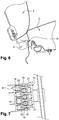
- a heating device implements an electrical connection zone 8 between the seat 2 and the backrest 3 , said zone 8 involving a first element 9 of electrical connection integral with the backrest 3, and a second element 10 of electrical connection integral with the seat 2, said two elements 9, 10 being able to cooperate to ensure an electrical connection between the folder 3 and the seat 2.
- the first connection element 9 is integral with a cross bar 11 of the structure of the backrest 3, by means of a support 12 which is welded to said bar 11.
- This bar 11 is substantially horizontal and extends along a transverse direction of the vehicle.
- This first connection element 9 schematically has five parallel walls 13, defining four compartments 14, aligned in a transverse direction of the vehicle.
- a current-conducting strip 15, having a throttle delimited by two walls of said strip 15, is inserted in each compartment 14 so as to come into contact with the faces delimiting said compartment 14.
- Each strip 15 is elastically deformable, so that the two walls delimiting the constriction may deviate from one another when an object is inserted between them. When said object is removed, the two walls naturally return to their initial positions.
- the heating device has a main electrical connector 16 secured to the structure of the backrest 3, and able to be connected to an electrical circuit of the vehicle so as to supply electric current to said heating device.
- This main electrical connector 16 is in electrical connection with the first electrical connection element 9, by means of four electrical wires 17, one end of each of said wires 17 ending in a terminal 18 intended to be inserted in the strip 15 lining the bottom of a compartment 14 of said first element 9.
- This main electrical connector 16 is also in electrical connection with a first electrical connector 19 secured to the structure of the backrest 3, said connection being effected by means of two electrical wires 20.
- This first electrical connector 19 is capable of being connected to a heating sheet of said backrest 3, said sheet comprising a wired electrical resistance.
- the second connection element 10 is integral with the structure of the seat 2, and has four studs 21 of substantially parallelepiped shape. These studs 21 are parallel and aligned in a transverse direction of the vehicle. They are intended to be inserted into the compartments 14 of the first connection element 9 by deforming the strips 15, essentially at their throttling. Indeed, the introduction of a stud 21 in the strip 15 of a compartment 14, will cause a separation of the two walls defining the constriction of said strip 15.
- This second connection element 10 is in electrical connection with a second electrical connector 22 fixed to a structure of the seat 2, said second connector 22 being able to be connected to a heating sheet of the seat 2, the operating principle of which is similar to that of the heating sheet of the backrest 3.
- the electrical connection between the second connection element 10 and the second connector 22 is produced by means of four electrical wires 23, one end of each of said wires 23 ending in a terminal 24 intended to be inserted in a strip 25 conductive, secured to each pad 21 of the second element connection 10.
- each stud 21 is extended by a current-carrying strip 25, which is fixed to the second electrical connection element 10.
- a user decides to enlarge the volume available in the vehicle in order to load elongated and / or bulky objects, he will retract the seat 1 according to the methods described above. To do this, it will start by separating the first connection element 9 and the second connection element 10 from the heating device, before then translating the seat 2 forwards. The separation of said two connection elements 9, 10 immediately leads to deactivation of the heating device.
Landscapes
- Engineering & Computer Science (AREA)
- Aviation & Aerospace Engineering (AREA)
- Transportation (AREA)
- Mechanical Engineering (AREA)
- Seats For Vehicles (AREA)
- Air-Conditioning For Vehicles (AREA)
- Chair Legs, Seat Parts, And Backrests (AREA)
Claims (10)
- Fahrzeugsitz (1), welcher ein Sitzteil (2), eine Rückenlehne (3) und eine Heizvorrichtung für das Sitzteil (2) und die Rückenlehne (3) umfasst, wobei der Sitz (1) dafür ausgelegt ist, mittels einer Trennung des Sitzteils (2) und der Rückenlehne (3) aus einer funktionalen Position in eine eingeklappte Position zu wechseln, dadurch gekennzeichnet, dass die Heizvorrichtung ein erstes elektrisches Verbindungselement (9), das mit der Rückenlehne (3) fest verbunden ist, und ein zweites elektrisches Verbindungselement (10), das mit dem Sitzteil (2) fest verbunden ist, umfasst, und dadurch, dass die beiden Elemente (9, 10) zusammenwirken, wenn sich der Sitz (1) in der funktionalen Position befindet, und getrennt werden können, um zu ermöglichen, dass sich der Sitz (1) in der eingeklappten Position befindet.
- Fahrzeugsitz nach Anspruch 1, dadurch gekennzeichnet, dass das erste Verbindungselement (9) und das zweite Verbindungselement (10) mittels einer Interaktion vom Typ Stecker/Buchse zusammenwirken.
- Fahrzeugsitz nach einem der Ansprüche 1 oder 2, dadurch gekennzeichnet, dass das erste Verbindungselement (9) wenigstens ein Abteil (14) aufweist, das in der Lage ist, den elektrischen Strom zu leiten, und dadurch, dass das zweite Verbindungselement (10) wenigstens ein vorstehendes Kontaktstück (21) umfasst, das in der Lage ist, den elektrischen Strom zu leiten, und dazu bestimmt ist, in dem Abteil (14) aufgenommen zu werden und sich dabei in Kontakt mit diesem zu befinden.
- Fahrzeugsitz nach Anspruch 3, dadurch gekennzeichnet, dass jedes Abteil (14) eine Lamelle (15) umfasst, die elastisch verformbar ist und in der Lage ist, den elektrischen Strom zu leiten, und dadurch, dass jedes Kontaktstück (21) in ein Abteil (14) eindringt und dabei die Lamelle (15) durch Kontakt verformt.
- Fahrzeugsitz nach einem der Ansprüche 1 bis 4, dadurch gekennzeichnet, dass er einen elektrischen Hauptsteckverbinder (16) umfasst, der mit der Rückenlehne (3) fest verbunden ist und an einen Stromkreis des Fahrzeugs anschließbar ist, und dadurch, dass der Hauptsteckverbinder (16) mit dem ersten Verbindungselement (9) in elektrischer Verbindung steht.
- Fahrzeugsitz nach Anspruch 5, dadurch gekennzeichnet, dass der Hauptsteckverbinder (16) mit einem ersten Verbinder (19) in elektrischer Verbindung steht, der mit der Rückenlehne (3) fest verbunden ist und an eine Heizeinlage der Rückenlehne (3) anschließbar ist.
- Fahrzeugsitz nach Anspruch 6, dadurch gekennzeichnet, dass die elektrische Verbindung zwischen dem elektrischen Hauptsteckverbinder (16) und dem ersten Verbinder (19) mittels wenigstens eines elektrischen Kabels (17) hergestellt ist.
- Fahrzeugsitz nach einem der Ansprüche 5 bis 7, dadurch gekennzeichnet, dass die elektrische Verbindung zwischen dem elektrischen Hauptsteckverbinder (16) und dem ersten Verbindungselement (9) mittels wenigstens eines Kabels (20) hergestellt ist.
- Fahrzeugsitz nach einem der Ansprüche 1 bis 8, dadurch gekennzeichnet, dass das zweite Verbindungselement (10) mit einem zweiten Verbinder (22) in elektrischer Verbindung steht, der mit dem Sitzteil (2) fest verbunden ist und an eine Heizeinlage des Sitzteils (2) anschließbar ist.
- Fahrzeugsitz nach Anspruch 9, dadurch gekennzeichnet, dass die elektrische Verbindung zwischen dem zweiten Verbindungselement (10) und dem zweiten Verbinder (22) mittels wenigstens eines elektrischen Kabels (23) hergestellt ist.
Applications Claiming Priority (1)
| Application Number | Priority Date | Filing Date | Title |
|---|---|---|---|
| FR1756695A FR3068933B1 (fr) | 2017-07-13 | 2017-07-13 | Siege de vehicule dote d'un dispositif de chauffage |
Publications (2)
| Publication Number | Publication Date |
|---|---|
| EP3428007A1 EP3428007A1 (de) | 2019-01-16 |
| EP3428007B1 true EP3428007B1 (de) | 2020-05-20 |
Family
ID=59930552
Family Applications (1)
| Application Number | Title | Priority Date | Filing Date |
|---|---|---|---|
| EP18181844.4A Active EP3428007B1 (de) | 2017-07-13 | 2018-07-05 | Fahrzeugsitz, der mit einer heizvorrichtung ausgestattet ist |
Country Status (2)
| Country | Link |
|---|---|
| EP (1) | EP3428007B1 (de) |
| FR (1) | FR3068933B1 (de) |
Citations (1)
| Publication number | Priority date | Publication date | Assignee | Title |
|---|---|---|---|---|
| US20100052390A1 (en) * | 2005-02-18 | 2010-03-04 | Johnson Controls Technology Company | Vehicle seating system |
Family Cites Families (5)
| Publication number | Priority date | Publication date | Assignee | Title |
|---|---|---|---|---|
| US5752845A (en) * | 1995-11-27 | 1998-05-19 | Lear Corporation | Modular seat with electrical connector |
| FR2816261B1 (fr) * | 2000-11-09 | 2003-01-31 | Cera | Element de siege de vehicule |
| DE102009039139A1 (de) * | 2009-08-27 | 2011-03-03 | GM Global Technology Operations, Inc., Detroit | Kraftfahrzeug mit einer hinteren Sitzanordnung |
| DE102012018261A1 (de) * | 2012-09-17 | 2014-03-20 | GM Global Technology Operations, LLC (n.d. Ges. d. Staates Delaware) | Schwenkgelenkanordnung für einen Fahrzeugsitz und Fahrzeugsitz mit der Schwenkgelenkanordnung |
| DE102014201569A1 (de) * | 2014-01-29 | 2015-07-30 | Leoni Bordnetz-Systeme Gmbh | Heizanordnung für ein Kraftfahrzeug und Heizelement für ein solches |
-
2017
- 2017-07-13 FR FR1756695A patent/FR3068933B1/fr not_active Expired - Fee Related
-
2018
- 2018-07-05 EP EP18181844.4A patent/EP3428007B1/de active Active
Patent Citations (1)
| Publication number | Priority date | Publication date | Assignee | Title |
|---|---|---|---|---|
| US20100052390A1 (en) * | 2005-02-18 | 2010-03-04 | Johnson Controls Technology Company | Vehicle seating system |
Also Published As
| Publication number | Publication date |
|---|---|
| EP3428007A1 (de) | 2019-01-16 |
| FR3068933B1 (fr) | 2019-08-09 |
| FR3068933A1 (fr) | 2019-01-18 |
Similar Documents
| Publication | Publication Date | Title |
|---|---|---|
| US9738185B1 (en) | System and method for providing a substantially horizontal resting area in passenger vehicles | |
| FR2804912A1 (fr) | Systeme d'agencement modulable des sieges dans un vehicule automobile | |
| FR2804913A1 (fr) | Systeme d'agencement modulable des sieges dans un vehicule automobile, notamment pour des sieges de premiere et deuxieme rangee | |
| FR3101291A1 (fr) | Siège de véhicule | |
| EP2780191B1 (de) | Sitzschiene | |
| FR2914593A1 (fr) | Siege de vehicule automobile comprenant un actionneur de deverrouillage de la translation longitudinale qui est active par une came | |
| EP2475549B1 (de) | Senkrecht bewegbares passagier-stützsystem für ein fahrzeug | |
| FR3068933B1 (fr) | Siege de vehicule dote d'un dispositif de chauffage | |
| FR2982805A1 (fr) | Dispositif de siege escamotable pour habitacle de vehicule | |
| FR2693156A1 (fr) | Aménagement de sièges dans un habitacle de véhicules automobiles. | |
| EP4563408A1 (de) | Fahrzeugsitz und fahrzeug mit einem solchen sitz | |
| FR3066463A1 (fr) | Commande de direction pour vehicule automobile retractable dans le siege | |
| WO2013050719A1 (fr) | Siege escamotable et cinematique de celui-ci | |
| FR2802485A3 (fr) | Vehicule automobile, en particulier camping-car, comprenant une table deplacable entre la zone de conduite et la zone de sejour | |
| FR2825330A1 (fr) | Siege pour vehicule automobile comportant un appui-tete dote d'un equipement electrique et appui-tete pour un tel siege | |
| FR2969058A1 (fr) | Siege de vehicule automobile dote d'un dispositif anti sous-marinage ameliore | |
| FR2986481A3 (fr) | Console centrale coulissante d'un vehicule automobile | |
| FR2834945A1 (fr) | Agencement de sieges pour vehicule automobile sur une armature d'arret de charge | |
| WO2012080663A1 (fr) | Siege de vehicule automobile | |
| FR2764850A1 (fr) | Appui-tete amovible de siege pour vehicule automobile et siege equipe d'un tel appui-tete | |
| FR2890911A1 (fr) | Vehicule automobile equipe de deux sieges lateraux mobiles transversalement et longitudinalement au vehicule et procede de transformation des sieges d'un tel vehicule | |
| EP1211125A1 (de) | Sitzeinheitanordnung im Innenraum eines Kraftfahrzeuges | |
| EP3800089B1 (de) | Fahrzeugsitz mit einer zusammenklappbaren rückenlehne, die in der lage ist, einen gegenstand zu tragen | |
| FR2966096A1 (fr) | Siege escamotable pour vehicule automobile | |
| FR3039469A1 (fr) | Banquette pour vehicule de transport comprenant un siege d'appoint |
Legal Events
| Date | Code | Title | Description |
|---|---|---|---|
| PUAI | Public reference made under article 153(3) epc to a published international application that has entered the european phase |
Free format text: ORIGINAL CODE: 0009012 |
|
| STAA | Information on the status of an ep patent application or granted ep patent |
Free format text: STATUS: THE APPLICATION HAS BEEN PUBLISHED |
|
| AK | Designated contracting states |
Kind code of ref document: A1 Designated state(s): AL AT BE BG CH CY CZ DE DK EE ES FI FR GB GR HR HU IE IS IT LI LT LU LV MC MK MT NL NO PL PT RO RS SE SI SK SM TR |
|
| AX | Request for extension of the european patent |
Extension state: BA ME |
|
| STAA | Information on the status of an ep patent application or granted ep patent |
Free format text: STATUS: REQUEST FOR EXAMINATION WAS MADE |
|
| 17P | Request for examination filed |
Effective date: 20190710 |
|
| RBV | Designated contracting states (corrected) |
Designated state(s): AL AT BE BG CH CY CZ DE DK EE ES FI FR GB GR HR HU IE IS IT LI LT LU LV MC MK MT NL NO PL PT RO RS SE SI SK SM TR |
|
| GRAP | Despatch of communication of intention to grant a patent |
Free format text: ORIGINAL CODE: EPIDOSNIGR1 |
|
| STAA | Information on the status of an ep patent application or granted ep patent |
Free format text: STATUS: GRANT OF PATENT IS INTENDED |
|
| INTG | Intention to grant announced |
Effective date: 20191219 |
|
| GRAS | Grant fee paid |
Free format text: ORIGINAL CODE: EPIDOSNIGR3 |
|
| GRAA | (expected) grant |
Free format text: ORIGINAL CODE: 0009210 |
|
| STAA | Information on the status of an ep patent application or granted ep patent |
Free format text: STATUS: THE PATENT HAS BEEN GRANTED |
|
| AK | Designated contracting states |
Kind code of ref document: B1 Designated state(s): AL AT BE BG CH CY CZ DE DK EE ES FI FR GB GR HR HU IE IS IT LI LT LU LV MC MK MT NL NO PL PT RO RS SE SI SK SM TR |
|
| REG | Reference to a national code |
Ref country code: GB Ref legal event code: FG4D Free format text: NOT ENGLISH |
|
| REG | Reference to a national code |
Ref country code: CH Ref legal event code: EP |
|
| REG | Reference to a national code |
Ref country code: DE Ref legal event code: R096 Ref document number: 602018004732 Country of ref document: DE |
|
| REG | Reference to a national code |
Ref country code: AT Ref legal event code: REF Ref document number: 1272401 Country of ref document: AT Kind code of ref document: T Effective date: 20200615 |
|
| REG | Reference to a national code |
Ref country code: LT Ref legal event code: MG4D |
|
| REG | Reference to a national code |
Ref country code: NL Ref legal event code: MP Effective date: 20200520 |
|
| PG25 | Lapsed in a contracting state [announced via postgrant information from national office to epo] |
Ref country code: GR Free format text: LAPSE BECAUSE OF FAILURE TO SUBMIT A TRANSLATION OF THE DESCRIPTION OR TO PAY THE FEE WITHIN THE PRESCRIBED TIME-LIMIT Effective date: 20200821 Ref country code: FI Free format text: LAPSE BECAUSE OF FAILURE TO SUBMIT A TRANSLATION OF THE DESCRIPTION OR TO PAY THE FEE WITHIN THE PRESCRIBED TIME-LIMIT Effective date: 20200520 Ref country code: PT Free format text: LAPSE BECAUSE OF FAILURE TO SUBMIT A TRANSLATION OF THE DESCRIPTION OR TO PAY THE FEE WITHIN THE PRESCRIBED TIME-LIMIT Effective date: 20200921 Ref country code: NO Free format text: LAPSE BECAUSE OF FAILURE TO SUBMIT A TRANSLATION OF THE DESCRIPTION OR TO PAY THE FEE WITHIN THE PRESCRIBED TIME-LIMIT Effective date: 20200820 Ref country code: IS Free format text: LAPSE BECAUSE OF FAILURE TO SUBMIT A TRANSLATION OF THE DESCRIPTION OR TO PAY THE FEE WITHIN THE PRESCRIBED TIME-LIMIT Effective date: 20200920 Ref country code: SE Free format text: LAPSE BECAUSE OF FAILURE TO SUBMIT A TRANSLATION OF THE DESCRIPTION OR TO PAY THE FEE WITHIN THE PRESCRIBED TIME-LIMIT Effective date: 20200520 Ref country code: LT Free format text: LAPSE BECAUSE OF FAILURE TO SUBMIT A TRANSLATION OF THE DESCRIPTION OR TO PAY THE FEE WITHIN THE PRESCRIBED TIME-LIMIT Effective date: 20200520 |
|
| PG25 | Lapsed in a contracting state [announced via postgrant information from national office to epo] |
Ref country code: BG Free format text: LAPSE BECAUSE OF FAILURE TO SUBMIT A TRANSLATION OF THE DESCRIPTION OR TO PAY THE FEE WITHIN THE PRESCRIBED TIME-LIMIT Effective date: 20200820 Ref country code: RS Free format text: LAPSE BECAUSE OF FAILURE TO SUBMIT A TRANSLATION OF THE DESCRIPTION OR TO PAY THE FEE WITHIN THE PRESCRIBED TIME-LIMIT Effective date: 20200520 Ref country code: HR Free format text: LAPSE BECAUSE OF FAILURE TO SUBMIT A TRANSLATION OF THE DESCRIPTION OR TO PAY THE FEE WITHIN THE PRESCRIBED TIME-LIMIT Effective date: 20200520 Ref country code: LV Free format text: LAPSE BECAUSE OF FAILURE TO SUBMIT A TRANSLATION OF THE DESCRIPTION OR TO PAY THE FEE WITHIN THE PRESCRIBED TIME-LIMIT Effective date: 20200520 |
|
| REG | Reference to a national code |
Ref country code: AT Ref legal event code: MK05 Ref document number: 1272401 Country of ref document: AT Kind code of ref document: T Effective date: 20200520 |
|
| PG25 | Lapsed in a contracting state [announced via postgrant information from national office to epo] |
Ref country code: NL Free format text: LAPSE BECAUSE OF FAILURE TO SUBMIT A TRANSLATION OF THE DESCRIPTION OR TO PAY THE FEE WITHIN THE PRESCRIBED TIME-LIMIT Effective date: 20200520 Ref country code: AL Free format text: LAPSE BECAUSE OF FAILURE TO SUBMIT A TRANSLATION OF THE DESCRIPTION OR TO PAY THE FEE WITHIN THE PRESCRIBED TIME-LIMIT Effective date: 20200520 |
|
| PG25 | Lapsed in a contracting state [announced via postgrant information from national office to epo] |
Ref country code: ES Free format text: LAPSE BECAUSE OF FAILURE TO SUBMIT A TRANSLATION OF THE DESCRIPTION OR TO PAY THE FEE WITHIN THE PRESCRIBED TIME-LIMIT Effective date: 20200520 Ref country code: AT Free format text: LAPSE BECAUSE OF FAILURE TO SUBMIT A TRANSLATION OF THE DESCRIPTION OR TO PAY THE FEE WITHIN THE PRESCRIBED TIME-LIMIT Effective date: 20200520 Ref country code: DK Free format text: LAPSE BECAUSE OF FAILURE TO SUBMIT A TRANSLATION OF THE DESCRIPTION OR TO PAY THE FEE WITHIN THE PRESCRIBED TIME-LIMIT Effective date: 20200520 Ref country code: EE Free format text: LAPSE BECAUSE OF FAILURE TO SUBMIT A TRANSLATION OF THE DESCRIPTION OR TO PAY THE FEE WITHIN THE PRESCRIBED TIME-LIMIT Effective date: 20200520 Ref country code: IT Free format text: LAPSE BECAUSE OF FAILURE TO SUBMIT A TRANSLATION OF THE DESCRIPTION OR TO PAY THE FEE WITHIN THE PRESCRIBED TIME-LIMIT Effective date: 20200520 Ref country code: SM Free format text: LAPSE BECAUSE OF FAILURE TO SUBMIT A TRANSLATION OF THE DESCRIPTION OR TO PAY THE FEE WITHIN THE PRESCRIBED TIME-LIMIT Effective date: 20200520 Ref country code: RO Free format text: LAPSE BECAUSE OF FAILURE TO SUBMIT A TRANSLATION OF THE DESCRIPTION OR TO PAY THE FEE WITHIN THE PRESCRIBED TIME-LIMIT Effective date: 20200520 Ref country code: CZ Free format text: LAPSE BECAUSE OF FAILURE TO SUBMIT A TRANSLATION OF THE DESCRIPTION OR TO PAY THE FEE WITHIN THE PRESCRIBED TIME-LIMIT Effective date: 20200520 |
|
| REG | Reference to a national code |
Ref country code: DE Ref legal event code: R097 Ref document number: 602018004732 Country of ref document: DE |
|
| PG25 | Lapsed in a contracting state [announced via postgrant information from national office to epo] |
Ref country code: MC Free format text: LAPSE BECAUSE OF FAILURE TO SUBMIT A TRANSLATION OF THE DESCRIPTION OR TO PAY THE FEE WITHIN THE PRESCRIBED TIME-LIMIT Effective date: 20200520 Ref country code: PL Free format text: LAPSE BECAUSE OF FAILURE TO SUBMIT A TRANSLATION OF THE DESCRIPTION OR TO PAY THE FEE WITHIN THE PRESCRIBED TIME-LIMIT Effective date: 20200520 Ref country code: SK Free format text: LAPSE BECAUSE OF FAILURE TO SUBMIT A TRANSLATION OF THE DESCRIPTION OR TO PAY THE FEE WITHIN THE PRESCRIBED TIME-LIMIT Effective date: 20200520 |
|
| PLBE | No opposition filed within time limit |
Free format text: ORIGINAL CODE: 0009261 |
|
| STAA | Information on the status of an ep patent application or granted ep patent |
Free format text: STATUS: NO OPPOSITION FILED WITHIN TIME LIMIT |
|
| 26N | No opposition filed |
Effective date: 20210223 |
|
| REG | Reference to a national code |
Ref country code: BE Ref legal event code: MM Effective date: 20200731 |
|
| PG25 | Lapsed in a contracting state [announced via postgrant information from national office to epo] |
Ref country code: IE Free format text: LAPSE BECAUSE OF NON-PAYMENT OF DUE FEES Effective date: 20200705 Ref country code: LU Free format text: LAPSE BECAUSE OF NON-PAYMENT OF DUE FEES Effective date: 20200705 |
|
| PG25 | Lapsed in a contracting state [announced via postgrant information from national office to epo] |
Ref country code: BE Free format text: LAPSE BECAUSE OF NON-PAYMENT OF DUE FEES Effective date: 20200731 Ref country code: SI Free format text: LAPSE BECAUSE OF FAILURE TO SUBMIT A TRANSLATION OF THE DESCRIPTION OR TO PAY THE FEE WITHIN THE PRESCRIBED TIME-LIMIT Effective date: 20200520 |
|
| REG | Reference to a national code |
Ref country code: CH Ref legal event code: PL |
|
| PG25 | Lapsed in a contracting state [announced via postgrant information from national office to epo] |
Ref country code: LI Free format text: LAPSE BECAUSE OF NON-PAYMENT OF DUE FEES Effective date: 20210731 Ref country code: CH Free format text: LAPSE BECAUSE OF NON-PAYMENT OF DUE FEES Effective date: 20210731 |
|
| PG25 | Lapsed in a contracting state [announced via postgrant information from national office to epo] |
Ref country code: TR Free format text: LAPSE BECAUSE OF FAILURE TO SUBMIT A TRANSLATION OF THE DESCRIPTION OR TO PAY THE FEE WITHIN THE PRESCRIBED TIME-LIMIT Effective date: 20200520 Ref country code: MT Free format text: LAPSE BECAUSE OF FAILURE TO SUBMIT A TRANSLATION OF THE DESCRIPTION OR TO PAY THE FEE WITHIN THE PRESCRIBED TIME-LIMIT Effective date: 20200520 Ref country code: CY Free format text: LAPSE BECAUSE OF FAILURE TO SUBMIT A TRANSLATION OF THE DESCRIPTION OR TO PAY THE FEE WITHIN THE PRESCRIBED TIME-LIMIT Effective date: 20200520 |
|
| PG25 | Lapsed in a contracting state [announced via postgrant information from national office to epo] |
Ref country code: MK Free format text: LAPSE BECAUSE OF FAILURE TO SUBMIT A TRANSLATION OF THE DESCRIPTION OR TO PAY THE FEE WITHIN THE PRESCRIBED TIME-LIMIT Effective date: 20200520 |
|
| GBPC | Gb: european patent ceased through non-payment of renewal fee |
Effective date: 20220705 |
|
| PG25 | Lapsed in a contracting state [announced via postgrant information from national office to epo] |
Ref country code: GB Free format text: LAPSE BECAUSE OF NON-PAYMENT OF DUE FEES Effective date: 20220705 |
|
| P01 | Opt-out of the competence of the unified patent court (upc) registered |
Effective date: 20230608 |
|
| PGFP | Annual fee paid to national office [announced via postgrant information from national office to epo] |
Ref country code: DE Payment date: 20250722 Year of fee payment: 8 |
|
| PGFP | Annual fee paid to national office [announced via postgrant information from national office to epo] |
Ref country code: FR Payment date: 20250725 Year of fee payment: 8 |