EP3427895A2 - Späneabsaugungskopfteil für ein werkzeug - Google Patents
Späneabsaugungskopfteil für ein werkzeug Download PDFInfo
- Publication number
- EP3427895A2 EP3427895A2 EP18181311.4A EP18181311A EP3427895A2 EP 3427895 A2 EP3427895 A2 EP 3427895A2 EP 18181311 A EP18181311 A EP 18181311A EP 3427895 A2 EP3427895 A2 EP 3427895A2
- Authority
- EP
- European Patent Office
- Prior art keywords
- headpiece
- shavings
- suction
- opening
- axis
- Prior art date
- Legal status (The legal status is an assumption and is not a legal conclusion. Google has not performed a legal analysis and makes no representation as to the accuracy of the status listed.)
- Granted
Links
Images


Classifications
-
- B—PERFORMING OPERATIONS; TRANSPORTING
- B23—MACHINE TOOLS; METAL-WORKING NOT OTHERWISE PROVIDED FOR
- B23Q—DETAILS, COMPONENTS, OR ACCESSORIES FOR MACHINE TOOLS, e.g. ARRANGEMENTS FOR COPYING OR CONTROLLING; MACHINE TOOLS IN GENERAL CHARACTERISED BY THE CONSTRUCTION OF PARTICULAR DETAILS OR COMPONENTS; COMBINATIONS OR ASSOCIATIONS OF METAL-WORKING MACHINES, NOT DIRECTED TO A PARTICULAR RESULT
- B23Q11/00—Accessories fitted to machine tools for keeping tools or parts of the machine in good working condition or for cooling work; Safety devices specially combined with or arranged in, or specially adapted for use in connection with, machine tools
- B23Q11/0042—Devices for removing chips
- B23Q11/0046—Devices for removing chips by sucking
-
- Y—GENERAL TAGGING OF NEW TECHNOLOGICAL DEVELOPMENTS; GENERAL TAGGING OF CROSS-SECTIONAL TECHNOLOGIES SPANNING OVER SEVERAL SECTIONS OF THE IPC; TECHNICAL SUBJECTS COVERED BY FORMER USPC CROSS-REFERENCE ART COLLECTIONS [XRACs] AND DIGESTS
- Y02—TECHNOLOGIES OR APPLICATIONS FOR MITIGATION OR ADAPTATION AGAINST CLIMATE CHANGE
- Y02P—CLIMATE CHANGE MITIGATION TECHNOLOGIES IN THE PRODUCTION OR PROCESSING OF GOODS
- Y02P70/00—Climate change mitigation technologies in the production process for final industrial or consumer products
- Y02P70/10—Greenhouse gas [GHG] capture, material saving, heat recovery or other energy efficient measures, e.g. motor control, characterised by manufacturing processes, e.g. for rolling metal or metal working
Definitions
- This invention relates to a shavings suction headpiece for a working tool, and relative working tool.
- the invention relates to a shavings suction headpiece for a working tool, in particular for milling, which is able to suck the shavings produced by the milling of materials, in particular wood, more efficiently.
- the headpiece according to the invention is able to partially modify its shape to allow the milling of edges of work pieces whilst continuing to guarantee an adequate suction of the shavings.
- the invention has originated within the research project "Local flexible manufacturing of green personalized furniture close to the customer in time, space and cost” (project partners: SCM Group Spa, University of Applied Science of Southern Switzerland, Synesis Consorzio with external activities, McNally & Finlay Limited, Milan Polytechnic, Missler Software, Technology Transfer System Srl, Veragouth SA, Innovawood ASBL, Hoch Engel Rosenheim).
- the shavings are produced in the working (drilling, sawing, milling, lathing) mainly of wood, but also of materials and metal alloys. In the case of the latter, it has been possible to partially renounce, by means of a shape finishing process, the working/post-working with the production of shavings, whilst this is not possible in the wooden products.
- the cleaning (absence of shavings) has an essential importance.
- the application apparatuses and the methods for measurement of the shavings can be considered to be crucial.
- the form of the shavings can be influenced mainly on the basis of the isotropic nature of the material of the piece (depending on the rigidity of the piece and the speed of turning, either some long spirals or many small flakes are produced).
- the market of machine tools comprises a complex market of accessories.
- a plurality of firms deal themselves with the use of the waste, starting from their production (see above) up to their separation and reuse.
- the so-called spatial suction devices 1 are those mainly used for the collection of shavings in CNC (Computer Numerical Control) working stations. In this case, a larger region is sucked around the milling tool 2. These spatial suction devices have the following drawbacks.
- this type of suction device is not very efficient. A large part of the shavings is not sucked and falls downwards. This results in an increased need for cleaning of the machine by the cleaning personnel as well as, partly, damage to the product (for example, scratches).
- the spatial suction devices consume considerable energy, since, on the basis of the speed of the air to be maintained as well as the resulting large currents, considerable electrical power is required.
- the problem of the collection of shavings in the working of wood is the drastic drop in suction speed with the increase in distance of the suction opening. That is to say, the collection of shavings reduces as the distance between the position of production of the shavings (work piece) and the suction opening increases. The minimising of the distance between the milling tool and the suction opening improves the degree of collection of the shavings.
- the advantage in this case is that the flow of air may be reduced, as the shavings which fall close to the tool are better collected and conveyed via the air flow.
- the suction opening 8 is positioned as close as possible around the tool 7.
- the suction headpieces used in this case are mainly linked to a particular size and cannot therefore be used with the particular tools and the aggregates.
- the aim of the invention is therefore to provide a headpiece and a suction apparatus which improves the degree and/or speed of removal of shavings in CNC machine tools and in the general 2D and 3D working.
- Another aim of this invention is to provide a headpiece and/or suction apparatus which allows an energy saving by the reduction of the suction air flow.
- the object of this invention is a device and an apparatus according to the accompanying claims, which form an integral part of this description.
- the headpiece according to the invention is formed by an upper portion d and by a lower portion e with respective edges b joined together (for example, in a removable fashion).
- the lower portion e consist of a first fixed part e f and a second part e v movable about the axis ax of the headpiece (see arrow in the drawing), in such a way as to superpose completely or partly the inside or outside of the fixed part e f .
- the parts e f and e v preferably have different dimensions, e f covering an angle of 3 /4 or /2 and e v covering an angle of /4 or /2 around ax.
- the purpose of the lower edge k of the lower portion is to make contact with the work piece, and it is therefore preferably formed by soft bristles.
- the lower edge k of the headpiece is divided into two parts corresponding to the edges of the parts e f and e v .
- variable part e v is guaranteed, for example, by means of a mechanical adjustment actuated electromechanically.
- This mechanical adjustment could be achieved, for example, by a gear wheel f mounted in a movable fashion, which crossing a gear wheel g is actuated by a servomotor h.
- the variable portion of headpiece e v is closed.
- the variable part of headpiece e v is open and for the working of three-dimensional pieces the variable part of headpiece e v is either open or closed.
- a suction tube i On the outer side of the upper half-headpiece d (but it is also possible on the lower fixed part e f ) is fixed a suction tube i in the tangential direction. More specifically, the evacuation tube i may be tangential to the headpiece, and this brings considerable advantages as described below.
- a sealing element j which may be adjustable in length.
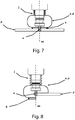
- Figure 7 clearly shows how the headpiece a,d according to the invention preferably has a shape with rotational symmetry about the axis ax, that is to say, about the working tool u.
- Figure 8 illustrates the machining of an edge of a piece p, and the variable part e v is superposed on the fixed part e f , and therefore not visible in this section.
- Figure 9 illustrates the machining of a three-dimensional piece p, in which the variable part e v is not superposed on the fixed part e f , and is therefore visible.
- Figure 10 illustrates the same situation as Figure 8 but with a three-dimensional view and in a very schematic fashion.
- the axis z corresponds to the axis ax and the mobile part e v has a circular extension on n angel of /2.
- the piece p is normally worked after having rested it on a support panel pm which is in turn rested on the machine surface dp.
- the same drawing illustrates two work situations with, respectively, the headpiece radially closed (on the left) and with the headpiece radially open (partially) (on the right).
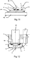
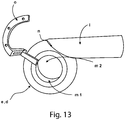
- the headpiece e,d may be of a toroidal shape with circular upper and lower openings m. Tangentially to the headpiece is fixed an evacuation tube i. On the edge of at least one opening m is fixed a rigid element (for example, made of metal) which is connected to the coupling body (not illustrated) of the tool by means of a rigid arm o.
- a rigid element for example, made of metal
- Figure 12 illustrates the headpiece in use in an electric spindle em.
- the term "bar” means an anti-rotation block, provided for safety reasons.
- the tube i joins ir with another tube is which forms an outlet upwards.
- the device for sucking shavings according to the invention must be shaped modularly or in an adaptive manner by means of elastic elements, according to the purpose of the milling cutter (the axis of rotation is orthogonal to the surface of the work piece or, on the other hand, laterally, the axis of rotation is parallel to the surface of the work piece).
- the suction headpiece is at a minimum distance from the milling cutter spindle. By means of this minimum distance to the milling spindle or to the work piece a relatively small volume is sufficient to achieve an exceptional level of collection of shavings.
- the preliminary tests with the suction headpiece according to the invention have reached a level of collection of shavings of up to 100%.
- the jet of shavings is also channelled and the rotation of the shavings is maintained.
- the shavings are conveyed directly into the suction tube. The degree of collection of the shavings is therefore significantly improved.
- Figures 14 to 26 show simulations, confirmed by laboratory tests, of the flow of air - and therefore of the shavings - in two headpieces with different geometries.
- the first headpiece d,e of Figure 14 is a headpiece according to the prior art, with an axial symmetry about the working tool u.
- the upper portion d is a cylinder, whilst the lower portion e is a ring obtained from the surface of a cup.
- An evacuation tube is connected to the first headpiece, radially to the headpiece.
- the second headpiece d,e of Figure 15 again has an axial symmetry about the working tool u.
- both the upper portion d and the lower portion e consist of a ring obtained from the surface of a cup.
- the two portions joined together have the approximate shape of an anchor ring.
- An evacuation tube is connected to the second headpiece, tangentially to the headpiece.
- Figures 16 and 17 show an important difference in the contour based (lines tangent to the speed range projected on the plane of the drawing) on the negative pressures in the plane XY in the median section of the suction tube. In fact, in the regions opposite the suction tube, the behaviour is different: in the headpiece with the tangential tube the speeds close to the walls are higher than that of the first headpiece with the radial tube.
- Figure 18 from (a) to (d) show an important difference in the speed vectors in the plane XY in the median section of the suction tube.
- the speed vectors are oriented to the headpiece in a radial manner, whilst in the modified headpiece these vectors are tangential. This effect is presumably due to the capacity of the modified headpiece to generate a mass of air in rotation with respect to the tool in an anticlockwise direction, favouring the escape of the shavings even in the most critical regions for the suction.
- Figures 19 and 20 show an important difference in the speed vectors in the plane XY in the median section of the headpiece.
- the entrance of the air from below through the bristles and the suction of the air from the tube create air vortices. These appear to be more intense and regular in the second nosepiece with the tangential tube with respect to the headpiece with the radial tube, thanks to the geometry of the modified upper headpiece (cup ring).
- the above-mentioned vortices are also visible in the plane ZX and also in this case in the most critical region (that is, opposite the suction tube) they are more intense and regular in the headpiece with the tangential tube.
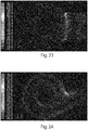
- Figures 23 and 24 show an important difference in the contour based on the negative pressures in the plane XY in the median section of the suction tube.
- the negative pressures generated inside the headpiece are at least double in the headpiece with the tangential tube with respect to those generated in the prior art headpieces.
- the headpiece according to the invention generates a negative pressure of greater than 24%.
- the invention applies to, amongst others, the wood and plastics industries, suction techniques, extraction techniques, and safety at the workplace.
Landscapes
- Engineering & Computer Science (AREA)
- Mechanical Engineering (AREA)
- Auxiliary Devices For Machine Tools (AREA)
Priority Applications (1)
| Application Number | Priority Date | Filing Date | Title |
|---|---|---|---|
| PL18181311T PL3427895T3 (pl) | 2017-07-13 | 2018-07-03 | Głowica odsysająca wióry do narzędzia roboczego |
Applications Claiming Priority (1)
| Application Number | Priority Date | Filing Date | Title |
|---|---|---|---|
| IT102017000078831A IT201700078831A1 (it) | 2017-07-13 | 2017-07-13 | Cuffia aspira-trucioli per utensile di lavorazione, e relativo utensile di lavorazione. |
Publications (3)
| Publication Number | Publication Date |
|---|---|
| EP3427895A2 true EP3427895A2 (de) | 2019-01-16 |
| EP3427895A3 EP3427895A3 (de) | 2019-03-27 |
| EP3427895B1 EP3427895B1 (de) | 2021-11-03 |
Family
ID=60570043
Family Applications (1)
| Application Number | Title | Priority Date | Filing Date |
|---|---|---|---|
| EP18181311.4A Active EP3427895B1 (de) | 2017-07-13 | 2018-07-03 | Späneabsaugungskopfteil für ein werkzeug |
Country Status (3)
| Country | Link |
|---|---|
| EP (1) | EP3427895B1 (de) |
| IT (1) | IT201700078831A1 (de) |
| PL (1) | PL3427895T3 (de) |
Cited By (6)
| Publication number | Priority date | Publication date | Assignee | Title |
|---|---|---|---|---|
| KR102256954B1 (ko) * | 2020-11-23 | 2021-05-26 | 김기수 | 집진 장치 |
| KR20210147741A (ko) * | 2020-05-29 | 2021-12-07 | 한국생산기술연구원 | 압력손실을 최소화하여 흡입성능을 향상시킬 수 있는 복합헤드용 드릴부, 이를 포함하는 복합헤드 및 복합헤드용 드릴부의 설계 방법 |
| KR20210147743A (ko) * | 2020-05-29 | 2021-12-07 | 한국생산기술연구원 | 분진 흡입 성능이 향상된 복합헤드용 드릴부의 설계 방법, 이에 의하여 설계된 복합헤드용 드릴부 및 이를 포함하는 복합헤드 |
| IT202300017826A1 (it) | 2023-08-30 | 2025-03-02 | Scm Group Spa | Metodo per regolare una portata di aspirazione di una macchina per la lavorazione del legno |
| IT202300017832A1 (it) | 2023-08-30 | 2025-03-02 | Scm Group Spa | Sistema di aspirazione del truciolo |
| EP4613425A1 (de) * | 2024-03-08 | 2025-09-10 | Geiss AG | Frässpindel für einen fräskopf und fräskopf, werkzeugmaschine und system |
Family Cites Families (4)
| Publication number | Priority date | Publication date | Assignee | Title |
|---|---|---|---|---|
| US4037982A (en) * | 1974-09-11 | 1977-07-26 | Infranor S.A. | Machine tools |
| DE4218247C2 (de) * | 1991-06-08 | 1995-05-18 | Wissner Rolf | Vorrichtung zur materialabtragenden Bearbeitung eines eine ebene Oberfläche aufweisenden Werkstücks |
| US6079078A (en) * | 1998-10-21 | 2000-06-27 | The Boeing Company | Chip and dust collection apparatus |
| ES2319028B1 (es) * | 2007-02-26 | 2010-02-10 | Airbus España, S.L. | Boquilla porta-avellanador. |
-
2017
- 2017-07-13 IT IT102017000078831A patent/IT201700078831A1/it unknown
-
2018
- 2018-07-03 PL PL18181311T patent/PL3427895T3/pl unknown
- 2018-07-03 EP EP18181311.4A patent/EP3427895B1/de active Active
Cited By (8)
| Publication number | Priority date | Publication date | Assignee | Title |
|---|---|---|---|---|
| KR20210147741A (ko) * | 2020-05-29 | 2021-12-07 | 한국생산기술연구원 | 압력손실을 최소화하여 흡입성능을 향상시킬 수 있는 복합헤드용 드릴부, 이를 포함하는 복합헤드 및 복합헤드용 드릴부의 설계 방법 |
| KR20210147743A (ko) * | 2020-05-29 | 2021-12-07 | 한국생산기술연구원 | 분진 흡입 성능이 향상된 복합헤드용 드릴부의 설계 방법, 이에 의하여 설계된 복합헤드용 드릴부 및 이를 포함하는 복합헤드 |
| KR102256954B1 (ko) * | 2020-11-23 | 2021-05-26 | 김기수 | 집진 장치 |
| IT202300017826A1 (it) | 2023-08-30 | 2025-03-02 | Scm Group Spa | Metodo per regolare una portata di aspirazione di una macchina per la lavorazione del legno |
| IT202300017832A1 (it) | 2023-08-30 | 2025-03-02 | Scm Group Spa | Sistema di aspirazione del truciolo |
| EP4516471A1 (de) | 2023-08-30 | 2025-03-05 | SCM Group S.p.A. | Méthode de régulation d'un débit de pression négative dans une machine à travailler le bois |
| EP4516450A1 (de) | 2023-08-30 | 2025-03-05 | SCM Group S.p.A. | Absaugvorrichtung für die späne in einer werkzeugmaschine |
| EP4613425A1 (de) * | 2024-03-08 | 2025-09-10 | Geiss AG | Frässpindel für einen fräskopf und fräskopf, werkzeugmaschine und system |
Also Published As
| Publication number | Publication date |
|---|---|
| EP3427895A3 (de) | 2019-03-27 |
| EP3427895B1 (de) | 2021-11-03 |
| IT201700078831A1 (it) | 2019-01-13 |
| PL3427895T3 (pl) | 2022-03-07 |
Similar Documents
| Publication | Publication Date | Title |
|---|---|---|
| EP3427895B1 (de) | Späneabsaugungskopfteil für ein werkzeug | |
| CN202053091U (zh) | 一种可重构的真空吸附夹具 | |
| CN105252051B (zh) | 带孔薄壁风扇壳体加工方法及工件定位工装 | |
| CN102825308B (zh) | 飞机结构件闭角清根方法 | |
| CN106774143A (zh) | 一种高温合金航空对开机匣五轴高速铣加工方法 | |
| CN105798632B (zh) | 车铣加工工艺 | |
| CN106271459A (zh) | 复杂曲面整体叶轮的加工方法 | |
| CN104551016B (zh) | 端面切槽装置 | |
| CN106514172A (zh) | 一种齿轮模具斜齿加工工艺 | |
| CN109434470A (zh) | 一种风叶的加工设备及方法 | |
| Park et al. | Modeling and grinding large sculptured surface by robotic digitization | |
| CN101587348A (zh) | 三维刃口轮廓的螺旋线插补加工方法 | |
| CN106077775B (zh) | 一种三轴机床加工倒扣类工件的加工方法 | |
| CN207004917U (zh) | 一种铣制半开式三元叶轮 | |
| CN105798633A (zh) | 车铣加工系统及车铣加工工艺 | |
| CN106141738A (zh) | 一种数控多工位除批锋装置 | |
| CN206230314U (zh) | 切屑吸引用罩及机床 | |
| CN203156054U (zh) | 一种锥形电机转子精加工车床 | |
| CN210081489U (zh) | 一种具有油雾处理装置的磨床 | |
| JPH07299630A (ja) | スクロール部材の成形方法 | |
| KR20180121939A (ko) | 회전 밀링 가공 시스템 및 회전 밀링 가공 방법 | |
| CN102784954A (zh) | 飞机结构件闭角清根专用刀具 | |
| WO2022256997A1 (zh) | 一种多功能倒角机 | |
| CN207267065U (zh) | 缸体内轮廓铣削专用机床 | |
| CN204687000U (zh) | 一种改进型木工线锯机 |
Legal Events
| Date | Code | Title | Description |
|---|---|---|---|
| PUAI | Public reference made under article 153(3) epc to a published international application that has entered the european phase |
Free format text: ORIGINAL CODE: 0009012 |
|
| STAA | Information on the status of an ep patent application or granted ep patent |
Free format text: STATUS: THE APPLICATION HAS BEEN PUBLISHED |
|
| AK | Designated contracting states |
Kind code of ref document: A2 Designated state(s): AL AT BE BG CH CY CZ DE DK EE ES FI FR GB GR HR HU IE IS IT LI LT LU LV MC MK MT NL NO PL PT RO RS SE SI SK SM TR |
|
| AX | Request for extension of the european patent |
Extension state: BA ME |
|
| PUAL | Search report despatched |
Free format text: ORIGINAL CODE: 0009013 |
|
| AK | Designated contracting states |
Kind code of ref document: A3 Designated state(s): AL AT BE BG CH CY CZ DE DK EE ES FI FR GB GR HR HU IE IS IT LI LT LU LV MC MK MT NL NO PL PT RO RS SE SI SK SM TR |
|
| AX | Request for extension of the european patent |
Extension state: BA ME |
|
| RIC1 | Information provided on ipc code assigned before grant |
Ipc: B23Q 11/00 20060101AFI20190221BHEP |
|
| STAA | Information on the status of an ep patent application or granted ep patent |
Free format text: STATUS: REQUEST FOR EXAMINATION WAS MADE |
|
| 17P | Request for examination filed |
Effective date: 20190920 |
|
| RBV | Designated contracting states (corrected) |
Designated state(s): AL AT BE BG CH CY CZ DE DK EE ES FI FR GB GR HR HU IE IS IT LI LT LU LV MC MK MT NL NO PL PT RO RS SE SI SK SM TR |
|
| GRAP | Despatch of communication of intention to grant a patent |
Free format text: ORIGINAL CODE: EPIDOSNIGR1 |
|
| STAA | Information on the status of an ep patent application or granted ep patent |
Free format text: STATUS: GRANT OF PATENT IS INTENDED |
|
| RIC1 | Information provided on ipc code assigned before grant |
Ipc: B23Q 11/00 20060101AFI20210505BHEP |
|
| INTG | Intention to grant announced |
Effective date: 20210607 |
|
| GRAS | Grant fee paid |
Free format text: ORIGINAL CODE: EPIDOSNIGR3 |
|
| GRAA | (expected) grant |
Free format text: ORIGINAL CODE: 0009210 |
|
| STAA | Information on the status of an ep patent application or granted ep patent |
Free format text: STATUS: THE PATENT HAS BEEN GRANTED |
|
| AK | Designated contracting states |
Kind code of ref document: B1 Designated state(s): AL AT BE BG CH CY CZ DE DK EE ES FI FR GB GR HR HU IE IS IT LI LT LU LV MC MK MT NL NO PL PT RO RS SE SI SK SM TR |
|
| REG | Reference to a national code |
Ref country code: GB Ref legal event code: FG4D |
|
| REG | Reference to a national code |
Ref country code: AT Ref legal event code: REF Ref document number: 1443543 Country of ref document: AT Kind code of ref document: T Effective date: 20211115 Ref country code: CH Ref legal event code: EP |
|
| REG | Reference to a national code |
Ref country code: IE Ref legal event code: FG4D |
|
| REG | Reference to a national code |
Ref country code: DE Ref legal event code: R096 Ref document number: 602018025975 Country of ref document: DE |
|
| REG | Reference to a national code |
Ref country code: LT Ref legal event code: MG9D |
|
| REG | Reference to a national code |
Ref country code: NL Ref legal event code: MP Effective date: 20211103 |
|
| PG25 | Lapsed in a contracting state [announced via postgrant information from national office to epo] |
Ref country code: RS Free format text: LAPSE BECAUSE OF FAILURE TO SUBMIT A TRANSLATION OF THE DESCRIPTION OR TO PAY THE FEE WITHIN THE PRESCRIBED TIME-LIMIT Effective date: 20211103 Ref country code: LT Free format text: LAPSE BECAUSE OF FAILURE TO SUBMIT A TRANSLATION OF THE DESCRIPTION OR TO PAY THE FEE WITHIN THE PRESCRIBED TIME-LIMIT Effective date: 20211103 Ref country code: FI Free format text: LAPSE BECAUSE OF FAILURE TO SUBMIT A TRANSLATION OF THE DESCRIPTION OR TO PAY THE FEE WITHIN THE PRESCRIBED TIME-LIMIT Effective date: 20211103 Ref country code: BG Free format text: LAPSE BECAUSE OF FAILURE TO SUBMIT A TRANSLATION OF THE DESCRIPTION OR TO PAY THE FEE WITHIN THE PRESCRIBED TIME-LIMIT Effective date: 20220203 |
|
| PG25 | Lapsed in a contracting state [announced via postgrant information from national office to epo] |
Ref country code: IS Free format text: LAPSE BECAUSE OF FAILURE TO SUBMIT A TRANSLATION OF THE DESCRIPTION OR TO PAY THE FEE WITHIN THE PRESCRIBED TIME-LIMIT Effective date: 20220303 Ref country code: SE Free format text: LAPSE BECAUSE OF FAILURE TO SUBMIT A TRANSLATION OF THE DESCRIPTION OR TO PAY THE FEE WITHIN THE PRESCRIBED TIME-LIMIT Effective date: 20211103 Ref country code: PT Free format text: LAPSE BECAUSE OF FAILURE TO SUBMIT A TRANSLATION OF THE DESCRIPTION OR TO PAY THE FEE WITHIN THE PRESCRIBED TIME-LIMIT Effective date: 20220303 Ref country code: NO Free format text: LAPSE BECAUSE OF FAILURE TO SUBMIT A TRANSLATION OF THE DESCRIPTION OR TO PAY THE FEE WITHIN THE PRESCRIBED TIME-LIMIT Effective date: 20220203 Ref country code: NL Free format text: LAPSE BECAUSE OF FAILURE TO SUBMIT A TRANSLATION OF THE DESCRIPTION OR TO PAY THE FEE WITHIN THE PRESCRIBED TIME-LIMIT Effective date: 20211103 Ref country code: LV Free format text: LAPSE BECAUSE OF FAILURE TO SUBMIT A TRANSLATION OF THE DESCRIPTION OR TO PAY THE FEE WITHIN THE PRESCRIBED TIME-LIMIT Effective date: 20211103 Ref country code: HR Free format text: LAPSE BECAUSE OF FAILURE TO SUBMIT A TRANSLATION OF THE DESCRIPTION OR TO PAY THE FEE WITHIN THE PRESCRIBED TIME-LIMIT Effective date: 20211103 Ref country code: GR Free format text: LAPSE BECAUSE OF FAILURE TO SUBMIT A TRANSLATION OF THE DESCRIPTION OR TO PAY THE FEE WITHIN THE PRESCRIBED TIME-LIMIT Effective date: 20220204 Ref country code: ES Free format text: LAPSE BECAUSE OF FAILURE TO SUBMIT A TRANSLATION OF THE DESCRIPTION OR TO PAY THE FEE WITHIN THE PRESCRIBED TIME-LIMIT Effective date: 20211103 |
|
| PG25 | Lapsed in a contracting state [announced via postgrant information from national office to epo] |
Ref country code: SM Free format text: LAPSE BECAUSE OF FAILURE TO SUBMIT A TRANSLATION OF THE DESCRIPTION OR TO PAY THE FEE WITHIN THE PRESCRIBED TIME-LIMIT Effective date: 20211103 Ref country code: SK Free format text: LAPSE BECAUSE OF FAILURE TO SUBMIT A TRANSLATION OF THE DESCRIPTION OR TO PAY THE FEE WITHIN THE PRESCRIBED TIME-LIMIT Effective date: 20211103 Ref country code: RO Free format text: LAPSE BECAUSE OF FAILURE TO SUBMIT A TRANSLATION OF THE DESCRIPTION OR TO PAY THE FEE WITHIN THE PRESCRIBED TIME-LIMIT Effective date: 20211103 Ref country code: EE Free format text: LAPSE BECAUSE OF FAILURE TO SUBMIT A TRANSLATION OF THE DESCRIPTION OR TO PAY THE FEE WITHIN THE PRESCRIBED TIME-LIMIT Effective date: 20211103 Ref country code: DK Free format text: LAPSE BECAUSE OF FAILURE TO SUBMIT A TRANSLATION OF THE DESCRIPTION OR TO PAY THE FEE WITHIN THE PRESCRIBED TIME-LIMIT Effective date: 20211103 Ref country code: CZ Free format text: LAPSE BECAUSE OF FAILURE TO SUBMIT A TRANSLATION OF THE DESCRIPTION OR TO PAY THE FEE WITHIN THE PRESCRIBED TIME-LIMIT Effective date: 20211103 |
|
| REG | Reference to a national code |
Ref country code: DE Ref legal event code: R097 Ref document number: 602018025975 Country of ref document: DE |
|
| PLBE | No opposition filed within time limit |
Free format text: ORIGINAL CODE: 0009261 |
|
| STAA | Information on the status of an ep patent application or granted ep patent |
Free format text: STATUS: NO OPPOSITION FILED WITHIN TIME LIMIT |
|
| 26N | No opposition filed |
Effective date: 20220804 |
|
| PG25 | Lapsed in a contracting state [announced via postgrant information from national office to epo] |
Ref country code: AL Free format text: LAPSE BECAUSE OF FAILURE TO SUBMIT A TRANSLATION OF THE DESCRIPTION OR TO PAY THE FEE WITHIN THE PRESCRIBED TIME-LIMIT Effective date: 20211103 |
|
| PG25 | Lapsed in a contracting state [announced via postgrant information from national office to epo] |
Ref country code: SI Free format text: LAPSE BECAUSE OF FAILURE TO SUBMIT A TRANSLATION OF THE DESCRIPTION OR TO PAY THE FEE WITHIN THE PRESCRIBED TIME-LIMIT Effective date: 20211103 |
|
| PG25 | Lapsed in a contracting state [announced via postgrant information from national office to epo] |
Ref country code: MC Free format text: LAPSE BECAUSE OF FAILURE TO SUBMIT A TRANSLATION OF THE DESCRIPTION OR TO PAY THE FEE WITHIN THE PRESCRIBED TIME-LIMIT Effective date: 20211103 |
|
| REG | Reference to a national code |
Ref country code: CH Ref legal event code: PL |
|
| GBPC | Gb: european patent ceased through non-payment of renewal fee |
Effective date: 20220703 |
|
| REG | Reference to a national code |
Ref country code: BE Ref legal event code: MM Effective date: 20220731 |
|
| PG25 | Lapsed in a contracting state [announced via postgrant information from national office to epo] |
Ref country code: LU Free format text: LAPSE BECAUSE OF NON-PAYMENT OF DUE FEES Effective date: 20220703 Ref country code: LI Free format text: LAPSE BECAUSE OF NON-PAYMENT OF DUE FEES Effective date: 20220731 Ref country code: FR Free format text: LAPSE BECAUSE OF NON-PAYMENT OF DUE FEES Effective date: 20220731 Ref country code: CH Free format text: LAPSE BECAUSE OF NON-PAYMENT OF DUE FEES Effective date: 20220731 |
|
| REG | Reference to a national code |
Ref country code: AT Ref legal event code: UEP Ref document number: 1443543 Country of ref document: AT Kind code of ref document: T Effective date: 20211103 |
|
| PG25 | Lapsed in a contracting state [announced via postgrant information from national office to epo] |
Ref country code: GB Free format text: LAPSE BECAUSE OF NON-PAYMENT OF DUE FEES Effective date: 20220703 Ref country code: BE Free format text: LAPSE BECAUSE OF NON-PAYMENT OF DUE FEES Effective date: 20220731 |
|
| P01 | Opt-out of the competence of the unified patent court (upc) registered |
Effective date: 20230518 |
|
| PG25 | Lapsed in a contracting state [announced via postgrant information from national office to epo] |
Ref country code: IE Free format text: LAPSE BECAUSE OF NON-PAYMENT OF DUE FEES Effective date: 20220703 |
|
| PG25 | Lapsed in a contracting state [announced via postgrant information from national office to epo] |
Ref country code: HU Free format text: LAPSE BECAUSE OF FAILURE TO SUBMIT A TRANSLATION OF THE DESCRIPTION OR TO PAY THE FEE WITHIN THE PRESCRIBED TIME-LIMIT; INVALID AB INITIO Effective date: 20180703 |
|
| PG25 | Lapsed in a contracting state [announced via postgrant information from national office to epo] |
Ref country code: MK Free format text: LAPSE BECAUSE OF FAILURE TO SUBMIT A TRANSLATION OF THE DESCRIPTION OR TO PAY THE FEE WITHIN THE PRESCRIBED TIME-LIMIT Effective date: 20211103 Ref country code: CY Free format text: LAPSE BECAUSE OF FAILURE TO SUBMIT A TRANSLATION OF THE DESCRIPTION OR TO PAY THE FEE WITHIN THE PRESCRIBED TIME-LIMIT Effective date: 20211103 |
|
| PG25 | Lapsed in a contracting state [announced via postgrant information from national office to epo] |
Ref country code: TR Free format text: LAPSE BECAUSE OF FAILURE TO SUBMIT A TRANSLATION OF THE DESCRIPTION OR TO PAY THE FEE WITHIN THE PRESCRIBED TIME-LIMIT Effective date: 20211103 |
|
| PG25 | Lapsed in a contracting state [announced via postgrant information from national office to epo] |
Ref country code: MT Free format text: LAPSE BECAUSE OF FAILURE TO SUBMIT A TRANSLATION OF THE DESCRIPTION OR TO PAY THE FEE WITHIN THE PRESCRIBED TIME-LIMIT Effective date: 20211103 |
|
| PGFP | Annual fee paid to national office [announced via postgrant information from national office to epo] |
Ref country code: PL Payment date: 20250624 Year of fee payment: 8 |
|
| PGFP | Annual fee paid to national office [announced via postgrant information from national office to epo] |
Ref country code: DE Payment date: 20250722 Year of fee payment: 8 |
|
| PGFP | Annual fee paid to national office [announced via postgrant information from national office to epo] |
Ref country code: IT Payment date: 20250708 Year of fee payment: 8 |
|
| PGFP | Annual fee paid to national office [announced via postgrant information from national office to epo] |
Ref country code: AT Payment date: 20250721 Year of fee payment: 8 |