EP3427895A2 - Shavings suction headpiece for a working tool - Google Patents
Shavings suction headpiece for a working tool Download PDFInfo
- Publication number
- EP3427895A2 EP3427895A2 EP18181311.4A EP18181311A EP3427895A2 EP 3427895 A2 EP3427895 A2 EP 3427895A2 EP 18181311 A EP18181311 A EP 18181311A EP 3427895 A2 EP3427895 A2 EP 3427895A2
- Authority
- EP
- European Patent Office
- Prior art keywords
- headpiece
- shavings
- suction
- opening
- axis
- Prior art date
- Legal status (The legal status is an assumption and is not a legal conclusion. Google has not performed a legal analysis and makes no representation as to the accuracy of the status listed.)
- Granted
Links
- 238000003801 milling Methods 0.000 abstract description 13
- 239000002023 wood Substances 0.000 abstract description 9
- 239000000463 material Substances 0.000 abstract description 6
- 239000003570 air Substances 0.000 description 15
- 239000013598 vector Substances 0.000 description 10
- 238000000034 method Methods 0.000 description 7
- 238000004519 manufacturing process Methods 0.000 description 5
- 238000012545 processing Methods 0.000 description 5
- 238000004088 simulation Methods 0.000 description 5
- 238000010586 diagram Methods 0.000 description 4
- 238000004140 cleaning Methods 0.000 description 3
- 230000000694 effects Effects 0.000 description 3
- 230000005611 electricity Effects 0.000 description 3
- 238000012360 testing method Methods 0.000 description 3
- 238000004458 analytical method Methods 0.000 description 2
- 238000005553 drilling Methods 0.000 description 2
- 238000005516 engineering process Methods 0.000 description 2
- 238000009533 lab test Methods 0.000 description 2
- 238000003754 machining Methods 0.000 description 2
- 239000002184 metal Substances 0.000 description 2
- 229910052751 metal Inorganic materials 0.000 description 2
- 238000011160 research Methods 0.000 description 2
- 238000007789 sealing Methods 0.000 description 2
- 238000000926 separation method Methods 0.000 description 2
- 230000003044 adaptive effect Effects 0.000 description 1
- 239000012080 ambient air Substances 0.000 description 1
- 238000000576 coating method Methods 0.000 description 1
- 238000012790 confirmation Methods 0.000 description 1
- 230000008878 coupling Effects 0.000 description 1
- 238000010168 coupling process Methods 0.000 description 1
- 238000005859 coupling reaction Methods 0.000 description 1
- 238000011161 development Methods 0.000 description 1
- 230000018109 developmental process Effects 0.000 description 1
- 238000000605 extraction Methods 0.000 description 1
- 238000007730 finishing process Methods 0.000 description 1
- 235000012054 meals Nutrition 0.000 description 1
- 238000005259 measurement Methods 0.000 description 1
- 229910001092 metal group alloy Inorganic materials 0.000 description 1
- 239000007769 metal material Substances 0.000 description 1
- 150000002739 metals Chemical class 0.000 description 1
- 239000004033 plastic Substances 0.000 description 1
- 229920003023 plastic Polymers 0.000 description 1
- 239000011148 porous material Substances 0.000 description 1
- 238000012546 transfer Methods 0.000 description 1
- 238000007514 turning Methods 0.000 description 1
- 239000002699 waste material Substances 0.000 description 1
Images


Classifications
-
- B—PERFORMING OPERATIONS; TRANSPORTING
- B23—MACHINE TOOLS; METAL-WORKING NOT OTHERWISE PROVIDED FOR
- B23Q—DETAILS, COMPONENTS, OR ACCESSORIES FOR MACHINE TOOLS, e.g. ARRANGEMENTS FOR COPYING OR CONTROLLING; MACHINE TOOLS IN GENERAL CHARACTERISED BY THE CONSTRUCTION OF PARTICULAR DETAILS OR COMPONENTS; COMBINATIONS OR ASSOCIATIONS OF METAL-WORKING MACHINES, NOT DIRECTED TO A PARTICULAR RESULT
- B23Q11/00—Accessories fitted to machine tools for keeping tools or parts of the machine in good working condition or for cooling work; Safety devices specially combined with or arranged in, or specially adapted for use in connection with, machine tools
- B23Q11/0042—Devices for removing chips
- B23Q11/0046—Devices for removing chips by sucking
-
- Y—GENERAL TAGGING OF NEW TECHNOLOGICAL DEVELOPMENTS; GENERAL TAGGING OF CROSS-SECTIONAL TECHNOLOGIES SPANNING OVER SEVERAL SECTIONS OF THE IPC; TECHNICAL SUBJECTS COVERED BY FORMER USPC CROSS-REFERENCE ART COLLECTIONS [XRACs] AND DIGESTS
- Y02—TECHNOLOGIES OR APPLICATIONS FOR MITIGATION OR ADAPTATION AGAINST CLIMATE CHANGE
- Y02P—CLIMATE CHANGE MITIGATION TECHNOLOGIES IN THE PRODUCTION OR PROCESSING OF GOODS
- Y02P70/00—Climate change mitigation technologies in the production process for final industrial or consumer products
- Y02P70/10—Greenhouse gas [GHG] capture, material saving, heat recovery or other energy efficient measures, e.g. motor control, characterised by manufacturing processes, e.g. for rolling metal or metal working
Abstract
Description
- This invention relates to a shavings suction headpiece for a working tool, and relative working tool.
- More specifically, the invention relates to a shavings suction headpiece for a working tool, in particular for milling, which is able to suck the shavings produced by the milling of materials, in particular wood, more efficiently. The headpiece according to the invention is able to partially modify its shape to allow the milling of edges of work pieces whilst continuing to guarantee an adequate suction of the shavings.
- The invention has originated within the research project "Local flexible manufacturing of green personalized furniture close to the customer in time, space and cost" (project partners: SCM Group Spa, University of Applied Science of Southern Switzerland, Synesis Consorzio with external activities, McNally & Finlay Limited, Milan Polytechnic, Missler Software, Technology Transfer System Srl, Veragouth SA, Innovawood ASBL, Hochschule Rosenheim).
- The shavings are produced in the working (drilling, sawing, milling, lathing) mainly of wood, but also of materials and metal alloys. In the case of the latter, it has been possible to partially renounce, by means of a shape finishing process, the working/post-working with the production of shavings, whilst this is not possible in the wooden products.
- Depending on the dimensional or precision requirements, it is often not possible to renounce the classic saws, milling cutters and drills. More specifically, in the case in which the old and new separation procedures are used in combination or in a high level of automation, the cleaning (absence of shavings) has an essential importance. The application apparatuses and the methods for measurement of the shavings can be considered to be crucial.
- Without doubt, in the working of allows and metal materials, the form of the shavings can be influenced mainly on the basis of the isotropic nature of the material of the piece (depending on the rigidity of the piece and the speed of turning, either some long spirals or many small flakes are produced).
- The market of machine tools comprises a complex market of accessories. A plurality of firms deal themselves with the use of the waste, starting from their production (see above) up to their separation and reuse. There are firms which deal with industries that process wood, industries which process metals or both. Potential interested parties and many others: suppliers of infrastructures and accessories.
- With reference to
Figure 1 , the so-calledspatial suction devices 1 are those mainly used for the collection of shavings in CNC (Computer Numerical Control) working stations. In this case, a larger region is sucked around themilling tool 2. These spatial suction devices have the following drawbacks. - Firstly, this type of suction device is not very efficient. A large part of the shavings is not sucked and falls downwards. This results in an increased need for cleaning of the machine by the cleaning personnel as well as, partly, damage to the product (for example, scratches).
- Moreover, the spatial suction devices consume considerable energy, since, on the basis of the speed of the air to be maintained as well as the resulting large currents, considerable electrical power is required.
- It is therefore necessary to improve the degree of collection of the shavings. The problem of the collection of shavings in the working of wood is the drastic drop in suction speed with the increase in distance of the suction opening. That is to say, the collection of shavings reduces as the distance between the position of production of the shavings (work piece) and the suction opening increases. The minimising of the distance between the milling tool and the suction opening improves the degree of collection of the shavings. The advantage in this case is that the flow of air may be reduced, as the shavings which fall close to the tool are better collected and conveyed via the air flow.
- The energy costs which have been increasing from many years represent a cost factor for many firms and therefore considerably affect the competitiveness. A potential significant optimisation lies mainly in the reduction of the energy requirements and, therefore, in the operating costs of the production processes. In the machines for working wood, the suction apparatus consumes on average 45% of the electricity demand, followed by the electricity consumption of the actual machine for working wood and the air pressure. It is therefore necessary to minimise the flow of air and, therefore, the electricity consumption.
- Research has been carried out in recent years in the field of CNC machine tools for improving the collection of shavings. With reference to
Figure 2 , the University of Stuttgart has conceived, in the field of working meals, a suction headpiece (not illustrated) according to the operation of a spiral band elastic 3 which has been tested in a CNC station for working wood. - In fact, there were already extensions for the use of collection devices as a function of the type of working. Different suction headpieces suitable for the working operations considered each time are replaced in that case for the process phase if the tool is changed. The University of Braunschweig has developed an optimised suction headpiece in this field with special sealing to the surface of the work piece (
Figure 3 ). - However, none of the developments described are widely applied in practice. The main reasons are that the surfaces of sensitive coatings are scratched or that these suction headpieces are only suitable for use in the case of flat surfaces.
- Different systems are used by manufacturers of machines and tools for improving the collection of shavings and in the field of shavings suction in practice. The problem in this case is that it is only mainly used for certain working operations. Additional tools are used, such as elements for conveying shavings of which an example is shown in
Figure 4 close to theworking tool 5 which works thepiece 6, which must convey the jet of shavings in the direction of the suction headpiece. - In order to improve the suction of the shavings, an attempt is also made in the machinery technology to make the spatial suction as small as possible. That is to say, with reference, for example, to
figure 5 , thesuction opening 8 is positioned as close as possible around thetool 7. The suction headpieces used in this case are mainly linked to a particular size and cannot therefore be used with the particular tools and the aggregates. - In addition, the influence has not been studied in the prior art of the influence of the particular shape of the headpiece on the speed of suction of the shavings, which is essential in the case of an increase in the working speed and when a large quantity of shavings is produced.
- The aim of the invention is therefore to provide a headpiece and a suction apparatus which improves the degree and/or speed of removal of shavings in CNC machine tools and in the general 2D and 3D working. Another aim of this invention is to provide a headpiece and/or suction apparatus which allows an energy saving by the reduction of the suction air flow.
- The object of this invention is a device and an apparatus according to the accompanying claims, which form an integral part of this description.
- The invention is now described, by way of example and without limiting the scope of the invention, with reference to the accompanying drawings, in which:
-
Figure 1 illustrates a first device for the suction of shavings according to the prior art; -
Figure 2 illustrates a second device for the suction of shavings according to the prior art; -
Figure 3 illustrates a third device for the suction of shavings according to the prior art; -
Figure 4 illustrates a fourth device for the suction of shavings according to the prior art; -
Figure 5 illustrates a fifth device for the suction of shavings according to the prior art; -
Figure 6 illustrates a diagram of a shavings suction headpiece according to the invention; -
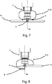
Figure 7 illustrates the processing of flat materials with an apparatus equipped with the headpiece according to the invention; -
Figure 8 illustrates the processing of the edges of a piece with an apparatus equipped with the headpiece according to the invention; -
Figure 9 illustrates the processing of the a three-dimensional piece with an apparatus equipped with the headpiece according to the invention; -
Figure 10 illustrates an approximate three-dimensional diagram of the headpiece according to the invention when an edge of a piece is processed; -
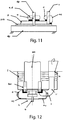
Figure 11 illustrates two possible forms of processing with the headpiece according to the invention, wherein the piece being processed is positioned on a support panel and on the machine surface; -
Figure 12 illustrates the headpiece according to the invention inside a processing apparatus; -
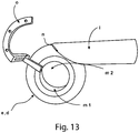
Figure 13 illustrates an example of toroidal embodiment of the headpiece according to the invention, with a tube for tangential evacuation of the shavings; -
Figure 14 illustrates a first embodiment of the headpiece according to the invention, with a radial evacuation tube (not shown), for a shavings evacuation test; -
Figure 15 illustrates a second embodiment of the headpiece according to the invention, which is toroidal and with a radial evacuation tube for the shavings evacuation test; -
Figure 16 illustrates a contour based on the speeds in the plane XY in the median section of the suction tube, for the headpiece ofFigure 14 ; -
Figure 17 illustrates a contour based on the speeds in the plane XY in the median section of the suction tube, for the headpiece ofFigure 15 ; -
Figure 18 illustrates in (a) and (b) the speed vectors in the plane XY in the median suction of the suction tube ((b) is a detail of (a)), for the headpiece ofFigure 14 ; and in (c) and (d) the speed vectors in the plane XY in the median section of the suction tube ((c) is a detail of (d)), for the headpiece ofFigure 15 ; -
Figure 19 illustrates the speed vectors in the plane ZY (ref.Figure 10 ) in the median section of the headpiece, for the headpiece ofFigure 14 ; -
Figure 20 illustrates the speed vectors in the plane ZY in the median section of the headpiece, for the headpiece ofFigure 15 ; -
Figure 21 illustrates the speed vectors in the plane ZX in the median section of the headpiece, for the headpiece ofFigure 14 ; -
Figure 22 illustrates the speed vectors in the plane ZX in the median section of the headpiece, for the headpiece ofFigure 15 ; -
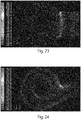
Figure 23 illustrates a contour based on the negative pressures in the plane XY in the median section of the suction tube, for the headpiece ofFigure 14 ; -
Figure 24 illustrates a contour based on the negative pressures in the plane XY in the median section of the suction tube, for the headpiece ofFigure 15 ; -
Figure 25 illustrates a diagram summarising the analyses of the previous drawings, wherein the possible trajectories for the air (and therefore the shavings) inside the headpiece ofFigure 14 are shown; and -
Figure 26 illustrates a diagram summarising the analyses of the previous drawings, wherein the possible trajectories for the air (and therefore the shavings) inside the headpiece ofFigure 15 are shown. - With reference to
Figure 6 , the headpiece according to the invention is formed by an upper portion d and by a lower portion e with respective edges b joined together (for example, in a removable fashion). - The lower portion e consist of a first fixed part ef and a second part ev movable about the axis ax of the headpiece (see arrow in the drawing), in such a way as to superpose completely or partly the inside or outside of the fixed part ef. The parts ef and ev preferably have different dimensions, ef covering an angle of 3 /4 or /2 and ev covering an angle of /4 or /2 around ax.
- The purpose of the lower edge k of the lower portion is to make contact with the work piece, and it is therefore preferably formed by soft bristles. The lower edge k of the headpiece is divided into two parts corresponding to the edges of the parts ef and ev.
- The opening and closing of the variable part ev is guaranteed, for example, by means of a mechanical adjustment actuated electromechanically. This mechanical adjustment could be achieved, for example, by a gear wheel f mounted in a movable fashion, which crossing a gear wheel g is actuated by a servomotor h. For the working of flat materials (for example, drilling, nesting etc.) the variable portion of headpiece ev is closed. For the working of edges, the variable part of headpiece ev is open and for the working of three-dimensional pieces the variable part of headpiece ev is either open or closed.
- On the outer side of the upper half-headpiece d (but it is also possible on the lower fixed part ef) is fixed a suction tube i in the tangential direction. More specifically, the evacuation tube i may be tangential to the headpiece, and this brings considerable advantages as described below.
- Between the suction headpiece (a or d/e) and the spindle there is a sealing element j which may be adjustable in length.
-
Figure 7 clearly shows how the headpiece a,d according to the invention preferably has a shape with rotational symmetry about the axis ax, that is to say, about the working tool u. -
Figure 8 illustrates the machining of an edge of a piece p, and the variable part ev is superposed on the fixed part ef, and therefore not visible in this section. -
Figure 9 illustrates the machining of a three-dimensional piece p, in which the variable part ev is not superposed on the fixed part ef, and is therefore visible. -
Figure 10 illustrates the same situation asFigure 8 but with a three-dimensional view and in a very schematic fashion. The axis z corresponds to the axis ax and the mobile part ev has a circular extension on n angel of /2. - With reference to
Figure 11 , the piece p is normally worked after having rested it on a support panel pm which is in turn rested on the machine surface dp. The same drawing illustrates two work situations with, respectively, the headpiece radially closed (on the left) and with the headpiece radially open (partially) (on the right). - With reference to
Figure 12 , the headpiece e,d may be of a toroidal shape with circular upper and lower openings m. Tangentially to the headpiece is fixed an evacuation tube i. On the edge of at least one opening m is fixed a rigid element (for example, made of metal) which is connected to the coupling body (not illustrated) of the tool by means of a rigid arm o. -
Figure 12 illustrates the headpiece in use in an electric spindle em. The term "bar" means an anti-rotation block, provided for safety reasons. The tube i joins ir with another tube is which forms an outlet upwards. - The device for sucking shavings according to the invention must be shaped modularly or in an adaptive manner by means of elastic elements, according to the purpose of the milling cutter (the axis of rotation is orthogonal to the surface of the work piece or, on the other hand, laterally, the axis of rotation is parallel to the surface of the work piece).
- With reference to
Figure 9 , due to the high level of adaptability provided by the headpiece, even convex 3D surfaces can be sucked. - The suction headpiece is at a minimum distance from the milling cutter spindle. By means of this minimum distance to the milling spindle or to the work piece a relatively small volume is sufficient to achieve an exceptional level of collection of shavings. The preliminary tests with the suction headpiece according to the invention have reached a level of collection of shavings of up to 100%.
- As a result of the form of the headpiece with a rotational symmetry as well as the tangential arrangement of the suction pipe, the jet of shavings is also channelled and the rotation of the shavings is maintained. By means of this, the shavings are conveyed directly into the suction tube. The degree of collection of the shavings is therefore significantly improved.
-
Figures 14 to 26 show simulations, confirmed by laboratory tests, of the flow of air - and therefore of the shavings - in two headpieces with different geometries. - The first headpiece d,e of
Figure 14 is a headpiece according to the prior art, with an axial symmetry about the working tool u. The upper portion d is a cylinder, whilst the lower portion e is a ring obtained from the surface of a cup. An evacuation tube is connected to the first headpiece, radially to the headpiece. - The second headpiece d,e of
Figure 15 , according to the invention, again has an axial symmetry about the working tool u. In this case, both the upper portion d and the lower portion e consist of a ring obtained from the surface of a cup. The two portions joined together have the approximate shape of an anchor ring. An evacuation tube is connected to the second headpiece, tangentially to the headpiece. - A series of simulations have been performed to observe the difference in efficiency of the two geometries. Other similar simulations and relative laboratory tests have been performed for different geometries.
- Some important boundary conditions for the CFD simulation have been:
- the speed of 25 m/s has been set on the section of the outlet tube;
- the tool is rotated at a speed of 2500 rad/s in an anticlockwise direction;
- the surfaces exposed to the ambient air have been put at an ambient pressure of 101325 Pa; and
- The volume occupied by the bristles is set as a porous material with a porosity of 0.1.
-
Figures 16 and 17 show an important difference in the contour based (lines tangent to the speed range projected on the plane of the drawing) on the negative pressures in the plane XY in the median section of the suction tube. In fact, in the regions opposite the suction tube, the behaviour is different: in the headpiece with the tangential tube the speeds close to the walls are higher than that of the first headpiece with the radial tube. - As confirmation,
Figure 18 from (a) to (d) show an important difference in the speed vectors in the plane XY in the median section of the suction tube. In fact, also in this case, in the regions opposite the suction tube, a different behaviour may be noted: in the first headpiece with the radial tube the speed vectors are oriented to the headpiece in a radial manner, whilst in the modified headpiece these vectors are tangential. This effect is presumably due to the capacity of the modified headpiece to generate a mass of air in rotation with respect to the tool in an anticlockwise direction, favouring the escape of the shavings even in the most critical regions for the suction. -
Figures 19 and 20 show an important difference in the speed vectors in the plane XY in the median section of the headpiece. In fact, it may be noted how the entrance of the air from below through the bristles and the suction of the air from the tube create air vortices. These appear to be more intense and regular in the second nosepiece with the tangential tube with respect to the headpiece with the radial tube, thanks to the geometry of the modified upper headpiece (cup ring). - With reference to
Figures 21 and 22 , the above-mentioned vortices are also visible in the plane ZX and also in this case in the most critical region (that is, opposite the suction tube) they are more intense and regular in the headpiece with the tangential tube. -
Figures 23 and 24 show an important difference in the contour based on the negative pressures in the plane XY in the median section of the suction tube. In fact, the negative pressures generated inside the headpiece are at least double in the headpiece with the tangential tube with respect to those generated in the prior art headpieces. - With reference to
Figures 25 and 26 , summarising the various effects seen previously, the possible trajectories for the air inside the two headpieces have been drawn. It may be noted that the air tends to be stationary in the regions furthest from the suction tube of the headpiece according to the prior art. The headpiece according to the invention shows, in the same regions, a significantly more efficient suction. This greater efficiency can also be inferred from the negative pressure generated on the outlet section: - original headpiece -1391.7 Pa;
- modified headpiece -1725.6 Pa.
- Therefore, with the same suction speed, the headpiece according to the invention generates a negative pressure of greater than 24%.
- The invention applies to, amongst others, the wood and plastics industries, suction techniques, extraction techniques, and safety at the workplace.
- The preferred embodiments have been described above and variants to the invention have been suggested, but it shall be understood that the invention may be modified and/or adapted by experts in the field without thereby departing from the scope of the inventive concept, as defined in the claims herein.
Claims (11)
- Shavings suction headpiece positionable around a working tool for a workpiece, the working tool having a main axis, comprising:- a first opening (m1);- a second opening (m2);- a side wall (e, d), extending between said first and said second opening, with axial symmetry about an axis (ax) passing through said first (m1) and second (m2) opening, said axis (ax) being, in use, substantially coincident with the main axis of said working tool (u);- a shavings evacuation tube (i) connected to said side wall (e, d) with airflow connection;- contact means (k) for said workpiece, the contact means being placed on the edge of said second opening (m2);The headpiece being characterized in that:- said side wall (e, d) is composed of a top portion (d) connected to a lower portion (e) with respect to the direction of said axis (ax);- said lower portion (e) is perimetrically subdivided around said axis (ax) into a first perimeter portion (ef) and a second perimeter portion (ev); and- said first perimeter portion (ef) and said second perimeter portion (ev) are configured to slide one over the other by rotating with respect to said axis (ax).
- Shavings suction headpiece according to claim 1, wherein said first perimeter portion (ef) is fixed and said second perimeter portion (ev) is movable.
- Shavings suction headpiece according to claim 1 or 2, wherein said first perimeter portion (ev) extends over an arc of /2 around said axis (ax).
- Shavings suction headpiece according to claim 1 or 2, wherein said first perimeter portion (ev) extends over an arc of /4 around said axis (ax).
- Shavings suction headpiece according to any one of the preceding claims, wherein said shavings evacuation tube (i) is substantially radially connected.
- Shavings suction headpiece according to any one of claims 1 to 4, wherein said shavings evacuation tube (i) is connected substantially tangentially to said lateral wall (e, d).
- Shavings suction headpiece according to claim 6, wherein said shavings evacuation tube (i) is substantially tangent to said upper portion (d).
- Shavings suction headpiece according to any one of the preceding claims, wherein said upper portion (d) is substantially equal to said lower portion (e).
- Shavings suction headpiece according to any one of the preceding claims, wherein said upper portion (d) is flush to said first opening (m1) and said lower portion (e) is flush to said second opening (m2).
- Shavings suction headpiece according to any one of the preceding claims, wherein said contact means (k) on the edge of said second opening comprise bristles.
- Shavings suction headpiece positionable around a working tool for a workpiece, the working tool having a main axis, comprising:- a first opening (m1);- a second opening (m2);- a side wall (e, d) extending between said first and said second openings with axial symmetry about an axis (ax) passing through said first (m1) and second (m2) opening, said axis (ax) being, in use, substantially coincident with the main axis of said working tool (u);- a shavings evacuation tube (i) connected to said side wall (e, d) by airflow connection;- contact means (k) for said workpiece placed on the edge of said second opening;The headpiece being characterized in that:- said shavings evacuation tube (i) is substantially tangential to said lateral wall (e, d).
Priority Applications (1)
| Application Number | Priority Date | Filing Date | Title |
|---|---|---|---|
| PL18181311T PL3427895T3 (en) | 2017-07-13 | 2018-07-03 | Shavings suction headpiece for a working tool |
Applications Claiming Priority (1)
| Application Number | Priority Date | Filing Date | Title |
|---|---|---|---|
| IT102017000078831A IT201700078831A1 (en) | 2017-07-13 | 2017-07-13 | Chip-suction cap for machining tool, and relative machining tool. |
Publications (3)
| Publication Number | Publication Date |
|---|---|
| EP3427895A2 true EP3427895A2 (en) | 2019-01-16 |
| EP3427895A3 EP3427895A3 (en) | 2019-03-27 |
| EP3427895B1 EP3427895B1 (en) | 2021-11-03 |
Family
ID=60570043
Family Applications (1)
| Application Number | Title | Priority Date | Filing Date |
|---|---|---|---|
| EP18181311.4A Active EP3427895B1 (en) | 2017-07-13 | 2018-07-03 | Shavings suction headpiece for a working tool |
Country Status (3)
| Country | Link |
|---|---|
| EP (1) | EP3427895B1 (en) |
| IT (1) | IT201700078831A1 (en) |
| PL (1) | PL3427895T3 (en) |
Cited By (3)
| Publication number | Priority date | Publication date | Assignee | Title |
|---|---|---|---|---|
| KR102256954B1 (en) * | 2020-11-23 | 2021-05-26 | 김기수 | Dust collector |
| KR20210147741A (en) * | 2020-05-29 | 2021-12-07 | 한국생산기술연구원 | Drill for composite head that can improve suction performance by minimizing pressure loss and composite head using the drill and design method of the drill |
| KR20210147743A (en) * | 2020-05-29 | 2021-12-07 | 한국생산기술연구원 | Method for designing a drill for composite head with improved dust suction performance and the drill for composite head designed thereby and the composite head using the drill |
Family Cites Families (4)
| Publication number | Priority date | Publication date | Assignee | Title |
|---|---|---|---|---|
| US4037982A (en) * | 1974-09-11 | 1977-07-26 | Infranor S.A. | Machine tools |
| DE4218247C2 (en) * | 1991-06-08 | 1995-05-18 | Wissner Rolf | Device for material-removing processing of a workpiece having a flat surface |
| US6079078A (en) * | 1998-10-21 | 2000-06-27 | The Boeing Company | Chip and dust collection apparatus |
| ES2319028B1 (en) * | 2007-02-26 | 2010-02-10 | Airbus España, S.L. | PORTA-AVELLANADOR NOZZLE. |
-
2017
- 2017-07-13 IT IT102017000078831A patent/IT201700078831A1/en unknown
-
2018
- 2018-07-03 PL PL18181311T patent/PL3427895T3/en unknown
- 2018-07-03 EP EP18181311.4A patent/EP3427895B1/en active Active
Cited By (3)
| Publication number | Priority date | Publication date | Assignee | Title |
|---|---|---|---|---|
| KR20210147741A (en) * | 2020-05-29 | 2021-12-07 | 한국생산기술연구원 | Drill for composite head that can improve suction performance by minimizing pressure loss and composite head using the drill and design method of the drill |
| KR20210147743A (en) * | 2020-05-29 | 2021-12-07 | 한국생산기술연구원 | Method for designing a drill for composite head with improved dust suction performance and the drill for composite head designed thereby and the composite head using the drill |
| KR102256954B1 (en) * | 2020-11-23 | 2021-05-26 | 김기수 | Dust collector |
Also Published As
| Publication number | Publication date |
|---|---|
| IT201700078831A1 (en) | 2019-01-13 |
| EP3427895B1 (en) | 2021-11-03 |
| PL3427895T3 (en) | 2022-03-07 |
| EP3427895A3 (en) | 2019-03-27 |
Similar Documents
| Publication | Publication Date | Title |
|---|---|---|
| EP3427895B1 (en) | Shavings suction headpiece for a working tool | |
| CN105364665A (en) | Novel single-head diamond circular platform grinding machine | |
| CN106514172A (en) | Oblique tooth machining process for gear mold | |
| CN109434470A (en) | A kind of process equipment and method of fan blade | |
| CN103586517B (en) | Narrow deep cavity numerical control milling method of integral impeller | |
| CN106077775B (en) | A kind of processing method of three axis machine tooling back-off class workpiece | |
| CN104742194A (en) | Inner circle cutting method | |
| CN101587348A (en) | Method for processing spiral line interpolation of three-dimensional cutting edge contour | |
| CN207004917U (en) | A kind of milling semi-open type 3 d impeller | |
| KR102134813B1 (en) | Rotary milling system and rotary milling method | |
| CN106141738A (en) | A kind of numerical control multi-station is except batch cutting edge of a knife or a sword device | |
| CN110449648A (en) | A kind of cutter and method for processing eccentric shaft sky knife | |
| Park et al. | Modeling and grinding large sculptured surface by robotic digitization | |
| CN209598671U (en) | A kind of process equipment of fan blade | |
| CN205765237U (en) | A kind of carving and milling machine with dust arrester | |
| CN209491568U (en) | A kind of main shaft trailing type dust exhaust apparatus | |
| CN204171811U (en) | The digital control plain surface grinding machine of grinding large saw-disc side end face | |
| CN102784954A (en) | Special cutter for cleaning up of closed corners of aircraft structural member | |
| CN109108390B (en) | Three-station deburring machining method | |
| CN205437975U (en) | High -efficient machine tooling production facility | |
| CN106583754A (en) | Motor flange end cover turning process | |
| CN204687000U (en) | A kind of modified carpenters line saw | |
| CN205465700U (en) | Multi -functional five -axis machine tool 's head of polishing | |
| CN104439366B (en) | A kind of turbine high-pressure outer shell back oblique flange hole Boring machine processing method | |
| WO2022256997A1 (en) | Multifunctional chamfering machine |
Legal Events
| Date | Code | Title | Description |
|---|---|---|---|
| PUAI | Public reference made under article 153(3) epc to a published international application that has entered the european phase |
Free format text: ORIGINAL CODE: 0009012 |
|
| STAA | Information on the status of an ep patent application or granted ep patent |
Free format text: STATUS: THE APPLICATION HAS BEEN PUBLISHED |
|
| AK | Designated contracting states |
Kind code of ref document: A2 Designated state(s): AL AT BE BG CH CY CZ DE DK EE ES FI FR GB GR HR HU IE IS IT LI LT LU LV MC MK MT NL NO PL PT RO RS SE SI SK SM TR |
|
| AX | Request for extension of the european patent |
Extension state: BA ME |
|
| PUAL | Search report despatched |
Free format text: ORIGINAL CODE: 0009013 |
|
| AK | Designated contracting states |
Kind code of ref document: A3 Designated state(s): AL AT BE BG CH CY CZ DE DK EE ES FI FR GB GR HR HU IE IS IT LI LT LU LV MC MK MT NL NO PL PT RO RS SE SI SK SM TR |
|
| AX | Request for extension of the european patent |
Extension state: BA ME |
|
| RIC1 | Information provided on ipc code assigned before grant |
Ipc: B23Q 11/00 20060101AFI20190221BHEP |
|
| STAA | Information on the status of an ep patent application or granted ep patent |
Free format text: STATUS: REQUEST FOR EXAMINATION WAS MADE |
|
| 17P | Request for examination filed |
Effective date: 20190920 |
|
| RBV | Designated contracting states (corrected) |
Designated state(s): AL AT BE BG CH CY CZ DE DK EE ES FI FR GB GR HR HU IE IS IT LI LT LU LV MC MK MT NL NO PL PT RO RS SE SI SK SM TR |
|
| GRAP | Despatch of communication of intention to grant a patent |
Free format text: ORIGINAL CODE: EPIDOSNIGR1 |
|
| STAA | Information on the status of an ep patent application or granted ep patent |
Free format text: STATUS: GRANT OF PATENT IS INTENDED |
|
| RIC1 | Information provided on ipc code assigned before grant |
Ipc: B23Q 11/00 20060101AFI20210505BHEP |
|
| INTG | Intention to grant announced |
Effective date: 20210607 |
|
| GRAS | Grant fee paid |
Free format text: ORIGINAL CODE: EPIDOSNIGR3 |
|
| GRAA | (expected) grant |
Free format text: ORIGINAL CODE: 0009210 |
|
| STAA | Information on the status of an ep patent application or granted ep patent |
Free format text: STATUS: THE PATENT HAS BEEN GRANTED |
|
| AK | Designated contracting states |
Kind code of ref document: B1 Designated state(s): AL AT BE BG CH CY CZ DE DK EE ES FI FR GB GR HR HU IE IS IT LI LT LU LV MC MK MT NL NO PL PT RO RS SE SI SK SM TR |
|
| REG | Reference to a national code |
Ref country code: GB Ref legal event code: FG4D |
|
| REG | Reference to a national code |
Ref country code: AT Ref legal event code: REF Ref document number: 1443543 Country of ref document: AT Kind code of ref document: T Effective date: 20211115 Ref country code: CH Ref legal event code: EP |
|
| REG | Reference to a national code |
Ref country code: IE Ref legal event code: FG4D |
|
| REG | Reference to a national code |
Ref country code: DE Ref legal event code: R096 Ref document number: 602018025975 Country of ref document: DE |
|
| REG | Reference to a national code |
Ref country code: LT Ref legal event code: MG9D |
|
| REG | Reference to a national code |
Ref country code: NL Ref legal event code: MP Effective date: 20211103 |
|
| PG25 | Lapsed in a contracting state [announced via postgrant information from national office to epo] |
Ref country code: RS Free format text: LAPSE BECAUSE OF FAILURE TO SUBMIT A TRANSLATION OF THE DESCRIPTION OR TO PAY THE FEE WITHIN THE PRESCRIBED TIME-LIMIT Effective date: 20211103 Ref country code: LT Free format text: LAPSE BECAUSE OF FAILURE TO SUBMIT A TRANSLATION OF THE DESCRIPTION OR TO PAY THE FEE WITHIN THE PRESCRIBED TIME-LIMIT Effective date: 20211103 Ref country code: FI Free format text: LAPSE BECAUSE OF FAILURE TO SUBMIT A TRANSLATION OF THE DESCRIPTION OR TO PAY THE FEE WITHIN THE PRESCRIBED TIME-LIMIT Effective date: 20211103 Ref country code: BG Free format text: LAPSE BECAUSE OF FAILURE TO SUBMIT A TRANSLATION OF THE DESCRIPTION OR TO PAY THE FEE WITHIN THE PRESCRIBED TIME-LIMIT Effective date: 20220203 |
|
| PG25 | Lapsed in a contracting state [announced via postgrant information from national office to epo] |
Ref country code: IS Free format text: LAPSE BECAUSE OF FAILURE TO SUBMIT A TRANSLATION OF THE DESCRIPTION OR TO PAY THE FEE WITHIN THE PRESCRIBED TIME-LIMIT Effective date: 20220303 Ref country code: SE Free format text: LAPSE BECAUSE OF FAILURE TO SUBMIT A TRANSLATION OF THE DESCRIPTION OR TO PAY THE FEE WITHIN THE PRESCRIBED TIME-LIMIT Effective date: 20211103 Ref country code: PT Free format text: LAPSE BECAUSE OF FAILURE TO SUBMIT A TRANSLATION OF THE DESCRIPTION OR TO PAY THE FEE WITHIN THE PRESCRIBED TIME-LIMIT Effective date: 20220303 Ref country code: NO Free format text: LAPSE BECAUSE OF FAILURE TO SUBMIT A TRANSLATION OF THE DESCRIPTION OR TO PAY THE FEE WITHIN THE PRESCRIBED TIME-LIMIT Effective date: 20220203 Ref country code: NL Free format text: LAPSE BECAUSE OF FAILURE TO SUBMIT A TRANSLATION OF THE DESCRIPTION OR TO PAY THE FEE WITHIN THE PRESCRIBED TIME-LIMIT Effective date: 20211103 Ref country code: LV Free format text: LAPSE BECAUSE OF FAILURE TO SUBMIT A TRANSLATION OF THE DESCRIPTION OR TO PAY THE FEE WITHIN THE PRESCRIBED TIME-LIMIT Effective date: 20211103 Ref country code: HR Free format text: LAPSE BECAUSE OF FAILURE TO SUBMIT A TRANSLATION OF THE DESCRIPTION OR TO PAY THE FEE WITHIN THE PRESCRIBED TIME-LIMIT Effective date: 20211103 Ref country code: GR Free format text: LAPSE BECAUSE OF FAILURE TO SUBMIT A TRANSLATION OF THE DESCRIPTION OR TO PAY THE FEE WITHIN THE PRESCRIBED TIME-LIMIT Effective date: 20220204 Ref country code: ES Free format text: LAPSE BECAUSE OF FAILURE TO SUBMIT A TRANSLATION OF THE DESCRIPTION OR TO PAY THE FEE WITHIN THE PRESCRIBED TIME-LIMIT Effective date: 20211103 |
|
| PG25 | Lapsed in a contracting state [announced via postgrant information from national office to epo] |
Ref country code: SM Free format text: LAPSE BECAUSE OF FAILURE TO SUBMIT A TRANSLATION OF THE DESCRIPTION OR TO PAY THE FEE WITHIN THE PRESCRIBED TIME-LIMIT Effective date: 20211103 Ref country code: SK Free format text: LAPSE BECAUSE OF FAILURE TO SUBMIT A TRANSLATION OF THE DESCRIPTION OR TO PAY THE FEE WITHIN THE PRESCRIBED TIME-LIMIT Effective date: 20211103 Ref country code: RO Free format text: LAPSE BECAUSE OF FAILURE TO SUBMIT A TRANSLATION OF THE DESCRIPTION OR TO PAY THE FEE WITHIN THE PRESCRIBED TIME-LIMIT Effective date: 20211103 Ref country code: EE Free format text: LAPSE BECAUSE OF FAILURE TO SUBMIT A TRANSLATION OF THE DESCRIPTION OR TO PAY THE FEE WITHIN THE PRESCRIBED TIME-LIMIT Effective date: 20211103 Ref country code: DK Free format text: LAPSE BECAUSE OF FAILURE TO SUBMIT A TRANSLATION OF THE DESCRIPTION OR TO PAY THE FEE WITHIN THE PRESCRIBED TIME-LIMIT Effective date: 20211103 Ref country code: CZ Free format text: LAPSE BECAUSE OF FAILURE TO SUBMIT A TRANSLATION OF THE DESCRIPTION OR TO PAY THE FEE WITHIN THE PRESCRIBED TIME-LIMIT Effective date: 20211103 |
|
| REG | Reference to a national code |
Ref country code: DE Ref legal event code: R097 Ref document number: 602018025975 Country of ref document: DE |
|
| PLBE | No opposition filed within time limit |
Free format text: ORIGINAL CODE: 0009261 |
|
| STAA | Information on the status of an ep patent application or granted ep patent |
Free format text: STATUS: NO OPPOSITION FILED WITHIN TIME LIMIT |
|
| 26N | No opposition filed |
Effective date: 20220804 |
|
| PG25 | Lapsed in a contracting state [announced via postgrant information from national office to epo] |
Ref country code: AL Free format text: LAPSE BECAUSE OF FAILURE TO SUBMIT A TRANSLATION OF THE DESCRIPTION OR TO PAY THE FEE WITHIN THE PRESCRIBED TIME-LIMIT Effective date: 20211103 |
|
| PG25 | Lapsed in a contracting state [announced via postgrant information from national office to epo] |
Ref country code: SI Free format text: LAPSE BECAUSE OF FAILURE TO SUBMIT A TRANSLATION OF THE DESCRIPTION OR TO PAY THE FEE WITHIN THE PRESCRIBED TIME-LIMIT Effective date: 20211103 |
|
| PG25 | Lapsed in a contracting state [announced via postgrant information from national office to epo] |
Ref country code: MC Free format text: LAPSE BECAUSE OF FAILURE TO SUBMIT A TRANSLATION OF THE DESCRIPTION OR TO PAY THE FEE WITHIN THE PRESCRIBED TIME-LIMIT Effective date: 20211103 |
|
| REG | Reference to a national code |
Ref country code: CH Ref legal event code: PL |
|
| GBPC | Gb: european patent ceased through non-payment of renewal fee |
Effective date: 20220703 |
|
| REG | Reference to a national code |
Ref country code: BE Ref legal event code: MM Effective date: 20220731 |
|
| PG25 | Lapsed in a contracting state [announced via postgrant information from national office to epo] |
Ref country code: LU Free format text: LAPSE BECAUSE OF NON-PAYMENT OF DUE FEES Effective date: 20220703 Ref country code: LI Free format text: LAPSE BECAUSE OF NON-PAYMENT OF DUE FEES Effective date: 20220731 Ref country code: FR Free format text: LAPSE BECAUSE OF NON-PAYMENT OF DUE FEES Effective date: 20220731 Ref country code: CH Free format text: LAPSE BECAUSE OF NON-PAYMENT OF DUE FEES Effective date: 20220731 |
|
| REG | Reference to a national code |
Ref country code: AT Ref legal event code: UEP Ref document number: 1443543 Country of ref document: AT Kind code of ref document: T Effective date: 20211103 |
|
| PG25 | Lapsed in a contracting state [announced via postgrant information from national office to epo] |
Ref country code: GB Free format text: LAPSE BECAUSE OF NON-PAYMENT OF DUE FEES Effective date: 20220703 Ref country code: BE Free format text: LAPSE BECAUSE OF NON-PAYMENT OF DUE FEES Effective date: 20220731 |
|
| P01 | Opt-out of the competence of the unified patent court (upc) registered |
Effective date: 20230518 |
|
| PG25 | Lapsed in a contracting state [announced via postgrant information from national office to epo] |
Ref country code: IE Free format text: LAPSE BECAUSE OF NON-PAYMENT OF DUE FEES Effective date: 20220703 |
|
| PGFP | Annual fee paid to national office [announced via postgrant information from national office to epo] |
Ref country code: PL Payment date: 20230622 Year of fee payment: 6 |
|
| PGFP | Annual fee paid to national office [announced via postgrant information from national office to epo] |
Ref country code: IT Payment date: 20230721 Year of fee payment: 6 Ref country code: AT Payment date: 20230718 Year of fee payment: 6 |
|
| PGFP | Annual fee paid to national office [announced via postgrant information from national office to epo] |
Ref country code: DE Payment date: 20230720 Year of fee payment: 6 |
|
| PG25 | Lapsed in a contracting state [announced via postgrant information from national office to epo] |
Ref country code: HU Free format text: LAPSE BECAUSE OF FAILURE TO SUBMIT A TRANSLATION OF THE DESCRIPTION OR TO PAY THE FEE WITHIN THE PRESCRIBED TIME-LIMIT; INVALID AB INITIO Effective date: 20180703 |