EP3427856A1 - Verfahren und vorrichtung zur herstellung eines laminierten eisenkerns - Google Patents
Verfahren und vorrichtung zur herstellung eines laminierten eisenkerns Download PDFInfo
- Publication number
- EP3427856A1 EP3427856A1 EP17763200.7A EP17763200A EP3427856A1 EP 3427856 A1 EP3427856 A1 EP 3427856A1 EP 17763200 A EP17763200 A EP 17763200A EP 3427856 A1 EP3427856 A1 EP 3427856A1
- Authority
- EP
- European Patent Office
- Prior art keywords
- steel strips
- feed rolls
- base steel
- iron core
- die
- Prior art date
- Legal status (The legal status is an assumption and is not a legal conclusion. Google has not performed a legal analysis and makes no representation as to the accuracy of the status listed.)
- Granted
Links
Images

Classifications
-
- B—PERFORMING OPERATIONS; TRANSPORTING
- B21—MECHANICAL METAL-WORKING WITHOUT ESSENTIALLY REMOVING MATERIAL; PUNCHING METAL
- B21D—WORKING OR PROCESSING OF SHEET METAL OR METAL TUBES, RODS OR PROFILES WITHOUT ESSENTIALLY REMOVING MATERIAL; PUNCHING METAL
- B21D28/00—Shaping by press-cutting; Perforating
- B21D28/02—Punching blanks or articles with or without obtaining scrap; Notching
- B21D28/22—Notching the peripheries of circular blanks, e.g. laminations for dynamo-electric machines
-
- B—PERFORMING OPERATIONS; TRANSPORTING
- B21—MECHANICAL METAL-WORKING WITHOUT ESSENTIALLY REMOVING MATERIAL; PUNCHING METAL
- B21D—WORKING OR PROCESSING OF SHEET METAL OR METAL TUBES, RODS OR PROFILES WITHOUT ESSENTIALLY REMOVING MATERIAL; PUNCHING METAL
- B21D43/00—Feeding, positioning or storing devices combined with, or arranged in, or specially adapted for use in connection with, apparatus for working or processing sheet metal, metal tubes or metal profiles; Associations therewith of cutting devices
- B21D43/02—Advancing work in relation to the stroke of the die or tool
- B21D43/04—Advancing work in relation to the stroke of the die or tool by means in mechanical engagement with the work
- B21D43/08—Advancing work in relation to the stroke of the die or tool by means in mechanical engagement with the work by rollers
- B21D43/09—Advancing work in relation to the stroke of the die or tool by means in mechanical engagement with the work by rollers by one or more pairs of rollers for feeding sheet or strip material
-
- B—PERFORMING OPERATIONS; TRANSPORTING
- B21—MECHANICAL METAL-WORKING WITHOUT ESSENTIALLY REMOVING MATERIAL; PUNCHING METAL
- B21D—WORKING OR PROCESSING OF SHEET METAL OR METAL TUBES, RODS OR PROFILES WITHOUT ESSENTIALLY REMOVING MATERIAL; PUNCHING METAL
- B21D28/00—Shaping by press-cutting; Perforating
- B21D28/02—Punching blanks or articles with or without obtaining scrap; Notching
-
- H—ELECTRICITY
- H01—ELECTRIC ELEMENTS
- H01F—MAGNETS; INDUCTANCES; TRANSFORMERS; SELECTION OF MATERIALS FOR THEIR MAGNETIC PROPERTIES
- H01F27/00—Details of transformers or inductances, in general
- H01F27/24—Magnetic cores
- H01F27/245—Magnetic cores made from sheets, e.g. grain-oriented
-
- H—ELECTRICITY
- H01—ELECTRIC ELEMENTS
- H01F—MAGNETS; INDUCTANCES; TRANSFORMERS; SELECTION OF MATERIALS FOR THEIR MAGNETIC PROPERTIES
- H01F41/00—Apparatus or processes specially adapted for manufacturing or assembling magnets, inductances or transformers; Apparatus or processes specially adapted for manufacturing materials characterised by their magnetic properties
- H01F41/02—Apparatus or processes specially adapted for manufacturing or assembling magnets, inductances or transformers; Apparatus or processes specially adapted for manufacturing materials characterised by their magnetic properties for manufacturing cores, coils, or magnets
- H01F41/0206—Manufacturing of magnetic cores by mechanical means
- H01F41/0233—Manufacturing of magnetic circuits made from sheets
- H01F41/024—Manufacturing of magnetic circuits made from deformed sheets
-
- H—ELECTRICITY
- H02—GENERATION; CONVERSION OR DISTRIBUTION OF ELECTRIC POWER
- H02K—DYNAMO-ELECTRIC MACHINES
- H02K15/00—Processes or apparatus specially adapted for manufacturing, assembling, maintaining or repairing of dynamo-electric machines
- H02K15/02—Processes or apparatus specially adapted for manufacturing, assembling, maintaining or repairing of dynamo-electric machines of stator or rotor bodies
-
- Y—GENERAL TAGGING OF NEW TECHNOLOGICAL DEVELOPMENTS; GENERAL TAGGING OF CROSS-SECTIONAL TECHNOLOGIES SPANNING OVER SEVERAL SECTIONS OF THE IPC; TECHNICAL SUBJECTS COVERED BY FORMER USPC CROSS-REFERENCE ART COLLECTIONS [XRACs] AND DIGESTS
- Y10—TECHNICAL SUBJECTS COVERED BY FORMER USPC
- Y10T—TECHNICAL SUBJECTS COVERED BY FORMER US CLASSIFICATION
- Y10T29/00—Metal working
- Y10T29/49—Method of mechanical manufacture
- Y10T29/49002—Electrical device making
- Y10T29/4902—Electromagnet, transformer or inductor
- Y10T29/49075—Electromagnet, transformer or inductor including permanent magnet or core
- Y10T29/49078—Laminated
Definitions
- the present invention relates to a method and a device for manufacturing a laminated iron core.
- the iron cores for motors and generators are manufactured by punching an electrical steel sheet having a thin sheet thickness, which is a base material, to prevent eddy current loss.
- a die for punching is set in a press machine, and while an electrical steel strip that has been slit in a predetermined width is fed into the die with a feeding device, each portion of the iron core is punched. Then, the iron core fragments are swaged in the die to be integrated, or the iron core fragments after being punched from the die are integrated by being welded or fixed by bolt, to be manufactured into the iron core.
- laminated iron core Such an iron core that is manufactured by laminating and integrating the electrical steel strips having a thin sheet thickness
- An industrial manufacturing process of iron cores generally uses a die referred to as a progressive die that has a plurality of punching processes in the die to manufacture the final iron cores while sequentially feeding the base steel strips in the die.
- a die referred to as a progressive die that has a plurality of punching processes in the die to manufacture the final iron cores while sequentially feeding the base steel strips in the die.
- Patent Literature 1 and Patent Literature 3 describe techniques of performing the punching process after joining the base steel strips to each other, which are not necessarily based on such a viewpoint.
- Patent Literature 1 describes, in a method of pressing by piling and feeding two steel sheets, the method of press working in which the steel sheets are pressed after portions to be scrapped are integrated by swaging or by welding.
- Patent Literature 3 describes a technique that provides coalescence locking portions for fixing on an iron-core forming portion and an iron-core non-forming portion, and that flattens the coalescence locking portions by pushing back. The techniques described in Patent Literature 1 and Patent Literature 3 are to avoid various problems that arise by steel sheets not being integrated with each other when the plurality of steel sheets are simultaneously fed into the die.
- the use of the up-and-down movement of a press machine excels in terms of simplicity, and it is preferable that the base steel strips be joined by swaging or applying an adhesive, at an upstream stage of the die installed in the press machine, or immediately before entering the die.
- the base steel strips be joined on the downstream side of the feed roll.
- the present invention has been made in consideration of the above-described problems, and an object thereof is to provide a method and a device for manufacturing a laminated iron core capable of manufacturing a laminated iron core by joining a plurality of electrical steel strips together while preventing the electrical steel strips from shifting in the width direction even when the electrical steel strips are fed at high speed by a feed roll.
- a laminated iron core manufacturing method is a method of manufacturing a laminated iron core by inserting a plurality of electrical steel strips in a superposed state to a pair of upper and lower feed rolls such that the electrical steel strips in a superposed state are fed into a die having a plurality of punching processes in sequence, and by simultaneously punching the plurality of electrical steel strips in a superposed state in the die, the method including: a joining step of joining a part or all of the superposed electrical steel strips together before entering the die or at an upstream stage portion of the die, after the electrical steel strips are fed out from the pair of upper and lower feed rolls by using feed rolls for which both upper and lower feed rolls are driven by a drive device as the pair of upper and lower feed rolls.
- surface roughness Ra of the pair of upper and lower feed rolls is 0.3 ⁇ m or more.
- a shift correction mechanism that corrects shift in a width direction of the electrical steel strips is installed at a position within 700 mm from a biting position of the pair of upper and lower feed rolls in a conveying direction of electrical steel strips.
- a rolling force applied to the pair of upper and lower feed rolls is controlled within a range of more than or equal to 1000 N and less than or equal to 2500 N.
- a manufacturing device for manufacturing a laminated iron core according to the present invention manufactures a laminated iron core by using the laminated iron core manufacturing method according to the present invention.
- the method and the device for manufacturing a laminated iron core in the present invention it is possible to manufacture a laminated iron core by joining a plurality of electrical steel strips together while preventing the electrical steel strips from shifting in the width direction even when the electrical steel strips are fed at high speed by the feed rolls.
- the inventors of the present invention have found that, as a result of earnest studies on a method for solving troubles due to lack of rigidity when a plurality of superposed base steel strips having a thin sheet thickness are punched, it is preferable to perform punching after joining a part or all of the base steel strips to each other, before entering a die or at an upstream process of the die, after being fed out from a feed roll, and have found that, at this time, troubles due to joining together the base steel strips being shifted in the width direction often occur. Then, the inventors of the present invention have found that, as a result of earnest investigations of the cause of such shift of the base steel strip in the width direction, there is a problem in the structure of a feed roll that is normally used.
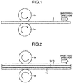
- the base steel strip 1c receives a force in the feed direction by the frictional force between the base steel strip 1c and the base steel strip 1b
- the upper roll 2b receives a force by the frictional force between the upper roll 2b and the base steel strip 1c and rotates.
- the feeding force is transmitted by the frictional force in sequence from the base steel strip on the lower side to the base steel strip on the upper side.
- the entire surfaces of the base steel strips are not necessarily in close contact to each other uniformly.
- the inventors of the present invention have concluded that the manner of transmitting the feeding force becomes asymmetric in the axial direction of the feed roll (width direction of the base steel strip), and that such asymmetry is increased as the feeding force is transmitted in sequence from the base steel strip on the lower side to the base steel strip on the upper side, and develops the shift of the base steel strip in the width direction.
- the inventors of the present invention have conceived that, as a solution to such a phenomenon, the upper roll is made to have a mechanism that actively rotates in synchronization with the lower roll. That is, the inventors of the present invention have conceived that, by transmitting the feeding force upward from the lower roll in sequence and by simultaneously transmitting the feeding force downward from the upper roll, the asymmetry of the feeding force by the frictional force between the base steel strips is eliminated and that the shift in the width direction between the base steel strips is prevented.
- a feeding device that drives both upper and lower feed rolls has been available.
- a feeding device is aimed at finely controlling the feeding amount of the base steel strip, and there is no example that uses it for punching in which a plurality of base steel strips are superposed and fed as in the present invention.
- the present invention is based on the above-described technical idea.
- the present invention by controlling the roughness of the surface of the feed rolls, by installing a mechanism that prevents the shift of the base steel strip in the width direction, and by further controlling the rolling force of the feed rolls, it is possible to sufficiently prevent the phenomenon in which the plurality of base steel strips shift in the width direction, and to stably perform punching process.
- a method that joins the plurality of base steel strips to each other immediately before a die or at an upstream stage of the die is suitable.
- the sheet thickness of the base steel strip is thinner, the rigidity thereof in the die is less and that is likely to lead to the troubles during punching, and thus it is desirable that the base steel strip be conveyed in the die after joining the base steel strips to each other.
- the above-described troubles during the punching depend on not only the sheet thickness of the base steel strip but also the size of the iron core obtained by the punching. Thus, the troubles are likely to occur in punching of the iron core having, roughly speaking, a sheet thickness of 0.30 mm or less and an outer shape of 120 mm or more.
- a pair of upper and lower feed rolls used in punching is of upper-and-lower-roll drive system.
- a feed roll that has been used in standard conventionally and for which only one side of the upper side and the lower side is driven is used, by the frictional force between the base steel strips, while the feeding force is transmitted between the superposed base steel strips and between the base steel strip and the driven roll, due to the undulations on the surface of the base steel strip and the non-uniformity in the friction coefficient, the feeding force becomes non-uniform in the width direction and the shift occurs in the width direction of the base steel strip.
- the feed roll of upper-and-lower-roll drive system means a pair of upper and lower feed rolls for which both feed rolls that come in contact with the base steel strip are coupled to a drive device, are actively driven, and are adjusted so that the operation timing of both is simultaneous.
- the surface roughness Ra of the pair of upper and lower feed rolls be 0.3 ⁇ m or more.
- the surface roughness Ra of the pair of upper and lower feed rolls be 0.3 ⁇ m or more, it is possible to further enhance the stability of the continuous punching process.
- the feeding force from the feed rolls that come in contact with the base steel strips from the upper side and the lower side is accurately transmitted to the base steel strips, and the shift of the base steel strips is prevented.
- the surface roughness Ra of the feed roll When the surface roughness Ra of the feed roll is below 0.3 ⁇ m, the frictional coefficient between the feed roll and the base steel strip decreases, the feed rate by the pair of upper and lower feed rolls is not stabilized, and the base steel strip is likely to shift in the width direction. It is desirable that the upper limit of the surface roughness Ra of the feed rolls be 3 ⁇ m. When the surface roughness Ra of the feed roll exceeds 3 ⁇ m, the contact state and pressed state between the base steel strip and the feed roll become non-uniform and the magnetic properties degrade.
- the shift correction mechanism that corrects the shift of the base steel strips in the width direction.
- the stability in continuous punching is further enhanced. This is because the shift of the base steel strip in the width direction is likely to occur due to the deviation in the sheet thickness and the like of the base steel strips, even when the feed rolls are driven together on both upper side and lower side and further properly controlling the surface roughness of the feed rolls.
- the shift correction mechanism operates effectively because the basic amount of shift is small, and it is possible to accurately align the width direction positions of the base steel strips.
- the shift correction mechanism As illustrated in FIG. 3 and FIG. 4 , a system that presses members 3 (see FIG. 3 ) or rotating rolls 4 (see FIG. 4 ) to the width-direction end portions of the base steel strips is effective.
- the base steel strip if the original amount of shift of the base steel strip in the width direction is large, because of the lack of rigidity of the base steel strip after the shift, the base steel strip is deformed before the position of the base steel strip is corrected, thereby making it difficult to correct the position in the width direction.
- Such a shift correction mechanism be installed in a range of 700 mm or less, preferably 400 mm or less, in the conveying direction of the electrical steel strip from the biting position of the feed rolls. Because the shift of the base steel strip in the width direction occurs at the biting position of the feed rolls, even if the positional shift in the width direction is forcibly corrected at a position away from the biting position of the feed rolls, it will not lead to drastic improvement. Meanwhile, by installing the shift correction mechanism at a proximity position of 700 mm or less from the biting position of the feed rolls, it is possible to prevent the shift of the base steel strip in the width direction at the biting position of the feed rolls.
- the shift correction mechanism is installed at a position exceeding 700 mm from the biting position of the feed rolls, because the base steel strip warps toward the lateral side between the shift correction mechanism and the feed rolls, the corrective action on the shift in the width direction at the biting position of the feed rolls is reduced. It is further effective that the shift correction mechanisms are installed at both inlet side and outlet side of the feed rolls. Moreover, by installing a plurality of shift correction mechanisms each at the inlet side and the outlet side, it is possible to easily correct the width direction position of the base steel strip without deforming the base steel strip in which the shift has occurred. When a plurality of shift correction mechanisms are installed, it is effective that as many shift correction mechanisms as possible are installed at positions within 700 mm from both of the inlet side and the outlet side of the feed rolls.
- the rolling force applied to the feed rolls be within a range more than or equal to 1000 N and less than or equal to 2500 N.
- the rolling force is not particularly limited, and because the slippage between the base steel strip and the feed roll is prevented when a strong rolling force within a range not adversely affecting the magnetic properties is applied, the rolling force applied to the feed rolls has generally been more than or equal to 3000 N.
- the inventors of the present invention have found that the feed rolls of upper-and-lower-roll drive system enables the rolling force applied to the feed rolls to be lower than that of the conventional case, thereby stably providing continuous press.
- the feed rolls of upper-and-lower-roll drive system are brought into contact with the superposed base steel strips from the up-and-down direction, and thus a large rolling force is not needed as compared with the conventional case, and a large rolling force can increase the shift in the width direction when the base steel strips used have width-direction uniformity such as sheet thickness deviation.
- the result of study of the inventors of the present invention revealed that by lowering the rolling force of the feed rolls the shift in the width direction between the base steel strips, and the continuous press workability was stabilized.
- the rolling force of the feed rolls that is weakened as compared with the conventional case causes the function of correcting the width direction position of the base steel strip, which tries to shift, at the biting position of the feed rolls by the shift correction mechanism to work effectively.
- the upper limit of the rolling force is preferably 2500 N, and is more preferably 2000 N. Meanwhile, if the rolling force is made too weak, the holding force at the feed rolls may become insufficient, and the feed rate of the base steel strip becomes unstable, or the shift in the width direction of the base steel strip easily occurs.
- the lower limit of the rolling force of the feed rolls is set to 1000 N.
- the device for manufacturing a laminated iron core according to the present invention includes a device having functions of dispensing and feeding base steel strips, which dispenses a plurality of base steel strips from a coil and superposes to feed the plurality of base steel strips to feed rolls, a pair of upper and lower feed rolls, a device having a function of integrating the plurality of base steel strips before entering a die from the feed rolls or at an upstream process in the die, the die that provides punching on the plurality of base steel strips in a superposed state, and a drive device that actively drives the pair of upper and lower feed rolls.
- the surface roughness Ra of the feed rolls be 0.3 ⁇ m or more. Furthermore, it is desirable that a shift correction mechanism that corrects shift in the width direction of the plurality of superposed base steel strips be provided on at least one side of the inlet side and the outlet side of the feed rolls and the shift correction mechanism be installed at a position within 700 mm from the biting position of the feed rolls in the conveying direction of the base steel strips. Moreover, it is desirable that the rolling force of the feed rolls be controlled within a range of more than or equal to 1000 N and less than or equal to 2500 N.
- the drive system of the feed rolls was performed by two systems of (a) driving of only one side roll (one side drive), and of (b) driving of both side rolls (upper-and-lower-roll drive), and both systems were compared. Furthermore, in (b) the driving of both side rolls, the surface roughness of the feed rolls and the rolling force to the feed rolls were varied. At positions before and after the feed rolls (before means before the base steel strips enter the feed rolls, and after means after the base steel strips are fed out from the feed rolls), guides for preventing and correcting the shift in the width direction of the two base steel strips were provided, and the guide positions were varied.
- a process that serves as both of the feeding of the base steel strips and the progress of adhesive was performed, by applying an adhesive between layers and superposing the base steel strips before the inlet side of a press machine (before feed rolls), and then by pinching the base steel strips from the up-and-down direction by the rotating feed rolls. Then, by feeding the base steel strips into a die in sequence, continuous punching was performed at a punching speed of 150 SPM by a punching die.
- the drive system of the feed rolls was performed by two systems of (a) driving of only one side roll (one side drive), and of (b) driving of both side rolls (upper-and-lower-roll drive), and both systems were compared. Furthermore, in (b) the driving of both side rolls, the surface roughness of the feed rolls and the rolling force to the feed rolls were varied. At positions before and after the feed rolls, guides for preventing and correcting the shift in the width direction of three base steel strips were provided, and the guide positions were varied.
Landscapes
- Engineering & Computer Science (AREA)
- Power Engineering (AREA)
- Manufacturing & Machinery (AREA)
- Mechanical Engineering (AREA)
- Manufacturing Cores, Coils, And Magnets (AREA)
- Manufacture Of Motors, Generators (AREA)
- Punching Or Piercing (AREA)
Applications Claiming Priority (2)
| Application Number | Priority Date | Filing Date | Title |
|---|---|---|---|
| JP2016048149A JP6477550B2 (ja) | 2016-03-11 | 2016-03-11 | 積層鉄心の製造方法及び製造装置 |
| PCT/JP2017/008886 WO2017154860A1 (ja) | 2016-03-11 | 2017-03-07 | 積層鉄心の製造方法及び製造装置 |
Publications (3)
| Publication Number | Publication Date |
|---|---|
| EP3427856A1 true EP3427856A1 (de) | 2019-01-16 |
| EP3427856A4 EP3427856A4 (de) | 2019-04-03 |
| EP3427856B1 EP3427856B1 (de) | 2023-09-20 |
Family
ID=59790477
Family Applications (1)
| Application Number | Title | Priority Date | Filing Date |
|---|---|---|---|
| EP17763200.7A Active EP3427856B1 (de) | 2016-03-11 | 2017-03-07 | Verfahren und vorrichtung zur herstellung eines laminierten eisenkerns |
Country Status (7)
| Country | Link |
|---|---|
| US (1) | US11117181B2 (de) |
| EP (1) | EP3427856B1 (de) |
| JP (1) | JP6477550B2 (de) |
| CN (1) | CN108778553B (de) |
| CA (1) | CA3017445C (de) |
| MX (1) | MX2018010950A (de) |
| WO (1) | WO2017154860A1 (de) |
Cited By (1)
| Publication number | Priority date | Publication date | Assignee | Title |
|---|---|---|---|---|
| EP4475152A4 (de) * | 2022-02-04 | 2025-05-07 | Nippon Steel Corporation | Vorrichtung zur herstellung eines gewickelten eisenkerns und verfahren zur herstellung eines gewickelten eisenkerns |
Families Citing this family (5)
| Publication number | Priority date | Publication date | Assignee | Title |
|---|---|---|---|---|
| WO2017174215A1 (en) * | 2016-04-05 | 2017-10-12 | Robert Bosch Gmbh | Process for blanking of metal parts |
| JP7154264B2 (ja) * | 2020-10-06 | 2022-10-17 | 三菱電機株式会社 | コアエレメントの製造方法と製造装置 |
| PL4235716T3 (pl) * | 2020-10-26 | 2025-06-09 | Nippon Steel Corporation | Rdzeń zwijany, sposób wytwarzania rdzenia zwijanego i urządzenie do wytwarzania rdzenia zwijanego |
| SI4235715T1 (sl) * | 2020-10-26 | 2025-07-31 | Nippon Steel Corporation | Navito železno jedro, metoda za izdelavo navitega železnega jedra in naprava za izdelavo navitega železnega jedra |
| CN113814318B (zh) * | 2021-09-25 | 2023-07-04 | 浙江实日机电科技有限公司 | 电机铁芯的生产工艺 |
Family Cites Families (15)
| Publication number | Priority date | Publication date | Assignee | Title |
|---|---|---|---|---|
| JPS4839615B1 (de) * | 1968-12-30 | 1973-11-26 | ||
| JPS5239880A (en) * | 1975-09-23 | 1977-03-28 | Matsushita Electric Ind Co Ltd | Method for punching a double steel tape continuously |
| JPS52126704A (en) | 1976-04-19 | 1977-10-24 | Hitachi Ltd | Manufacturing method for electric machine core |
| JPS55156623A (en) | 1979-05-23 | 1980-12-05 | Shinko Electric Co Ltd | Blanking method for overlapped double sheets for iron core of electrical machinery and apparatus |
| JPS57156657A (en) | 1981-06-22 | 1982-09-28 | Mitsui Haitetsuku:Kk | Manufacture of laminated iron core |
| JPS6015412U (ja) * | 1983-07-06 | 1985-02-01 | 新日本製鐵株式会社 | 金属帯のサイドガイド装置 |
| JP2001016832A (ja) * | 1999-06-28 | 2001-01-19 | Shosuke Noguchi | プレスによる鉄心板の打抜方法 |
| CN2470018Y (zh) * | 2000-07-19 | 2002-01-09 | 攀枝花新钢钒股份有限公司热轧板厂 | 改良辊形的卷取机夹送辊 |
| JP4472386B2 (ja) | 2004-03-10 | 2010-06-02 | 株式会社三井ハイテック | 積層鉄心の製造方法 |
| CN100441490C (zh) | 2005-07-01 | 2008-12-10 | 西安重型机械研究所 | 一种开头夹送辊的控制方法及装置 |
| JP5630150B2 (ja) * | 2010-08-31 | 2014-11-26 | トヨタ紡織株式会社 | パンチング装置 |
| JP2012231590A (ja) * | 2011-04-26 | 2012-11-22 | Toyota Motor Corp | 絶縁体製造装置および絶縁体製造方法 |
| CN103316989B (zh) | 2012-03-23 | 2015-05-06 | 新疆特变电工集团有限公司 | 一种硅钢片数控冲剪线设备 |
| JP6587800B2 (ja) * | 2014-12-26 | 2019-10-09 | Jfeスチール株式会社 | 積層鉄心の製造方法 |
| JP5958565B2 (ja) * | 2015-01-14 | 2016-08-02 | Jfeスチール株式会社 | 打抜き加工方法、打抜き加工装置、および積層鉄心の製造方法 |
-
2016
- 2016-03-11 JP JP2016048149A patent/JP6477550B2/ja active Active
-
2017
- 2017-03-07 WO PCT/JP2017/008886 patent/WO2017154860A1/ja not_active Ceased
- 2017-03-07 EP EP17763200.7A patent/EP3427856B1/de active Active
- 2017-03-07 MX MX2018010950A patent/MX2018010950A/es unknown
- 2017-03-07 CN CN201780016165.XA patent/CN108778553B/zh active Active
- 2017-03-07 US US16/082,698 patent/US11117181B2/en active Active
- 2017-03-07 CA CA3017445A patent/CA3017445C/en active Active
Cited By (1)
| Publication number | Priority date | Publication date | Assignee | Title |
|---|---|---|---|---|
| EP4475152A4 (de) * | 2022-02-04 | 2025-05-07 | Nippon Steel Corporation | Vorrichtung zur herstellung eines gewickelten eisenkerns und verfahren zur herstellung eines gewickelten eisenkerns |
Also Published As
| Publication number | Publication date |
|---|---|
| US20190099800A1 (en) | 2019-04-04 |
| CA3017445A1 (en) | 2017-09-14 |
| EP3427856B1 (de) | 2023-09-20 |
| JP6477550B2 (ja) | 2019-03-06 |
| US11117181B2 (en) | 2021-09-14 |
| MX2018010950A (es) | 2018-11-22 |
| CN108778553A (zh) | 2018-11-09 |
| JP2017159347A (ja) | 2017-09-14 |
| CA3017445C (en) | 2021-07-27 |
| WO2017154860A1 (ja) | 2017-09-14 |
| EP3427856A4 (de) | 2019-04-03 |
| CN108778553B (zh) | 2020-04-24 |
Similar Documents
| Publication | Publication Date | Title |
|---|---|---|
| EP3427856B1 (de) | Verfahren und vorrichtung zur herstellung eines laminierten eisenkerns | |
| CA2971381C (en) | Punch processing method for laminated iron core and method for manufacturing laminated iron core | |
| EP3246105B1 (de) | Stanzverfahren und verfahren zur herstellung eines laminierten kerns | |
| EP3213831B1 (de) | Progressives verarbeitungsverfahren | |
| EP3345691B1 (de) | Vorrichtung zur herstellung eines blechkerns und verfahren zur herstellung eines blechkerns | |
| JP6094146B2 (ja) | 回転電機の固定子鉄心の製造方法 | |
| JP6392089B2 (ja) | 打抜き方法及び打抜き装置並びに積層鉄心の製造方法 | |
| EP3345692B1 (de) | Vorrichtung zur herstellung eines blechkerns und verfahren zur herstellung eines blechkerns | |
| US12597832B2 (en) | Method for laminated core of rotating electric machine | |
| US20230129627A1 (en) | Manufacturing method for laminated core of rotating electric machine, and manufacturing apparatus for laminated core of rotating electric machine | |
| JP6349501B2 (ja) | 電磁鋼板プレス金型構造 |
Legal Events
| Date | Code | Title | Description |
|---|---|---|---|
| STAA | Information on the status of an ep patent application or granted ep patent |
Free format text: STATUS: THE INTERNATIONAL PUBLICATION HAS BEEN MADE |
|
| PUAI | Public reference made under article 153(3) epc to a published international application that has entered the european phase |
Free format text: ORIGINAL CODE: 0009012 |
|
| STAA | Information on the status of an ep patent application or granted ep patent |
Free format text: STATUS: REQUEST FOR EXAMINATION WAS MADE |
|
| 17P | Request for examination filed |
Effective date: 20181008 |
|
| AK | Designated contracting states |
Kind code of ref document: A1 Designated state(s): AL AT BE BG CH CY CZ DE DK EE ES FI FR GB GR HR HU IE IS IT LI LT LU LV MC MK MT NL NO PL PT RO RS SE SI SK SM TR |
|
| AX | Request for extension of the european patent |
Extension state: BA ME |
|
| REG | Reference to a national code |
Ref country code: DE Ref legal event code: R079 Free format text: PREVIOUS MAIN CLASS: B21D0028020000 Ipc: B21D0043090000 Ref country code: DE Ref legal event code: R079 Ref document number: 602017074430 Country of ref document: DE Free format text: PREVIOUS MAIN CLASS: B21D0028020000 Ipc: B21D0043090000 |
|
| A4 | Supplementary search report drawn up and despatched |
Effective date: 20190306 |
|
| RIC1 | Information provided on ipc code assigned before grant |
Ipc: H01F 41/02 20060101ALI20190226BHEP Ipc: B21D 43/09 20060101AFI20190226BHEP Ipc: H01F 27/245 20060101ALI20190226BHEP Ipc: H02K 15/02 20060101ALI20190226BHEP Ipc: B21D 28/22 20060101ALI20190226BHEP |
|
| DAV | Request for validation of the european patent (deleted) | ||
| DAX | Request for extension of the european patent (deleted) | ||
| STAA | Information on the status of an ep patent application or granted ep patent |
Free format text: STATUS: EXAMINATION IS IN PROGRESS |
|
| 17Q | First examination report despatched |
Effective date: 20211209 |
|
| GRAP | Despatch of communication of intention to grant a patent |
Free format text: ORIGINAL CODE: EPIDOSNIGR1 |
|
| STAA | Information on the status of an ep patent application or granted ep patent |
Free format text: STATUS: GRANT OF PATENT IS INTENDED |
|
| INTG | Intention to grant announced |
Effective date: 20230530 |
|
| GRAS | Grant fee paid |
Free format text: ORIGINAL CODE: EPIDOSNIGR3 |
|
| GRAA | (expected) grant |
Free format text: ORIGINAL CODE: 0009210 |
|
| STAA | Information on the status of an ep patent application or granted ep patent |
Free format text: STATUS: THE PATENT HAS BEEN GRANTED |
|
| AK | Designated contracting states |
Kind code of ref document: B1 Designated state(s): AL AT BE BG CH CY CZ DE DK EE ES FI FR GB GR HR HU IE IS IT LI LT LU LV MC MK MT NL NO PL PT RO RS SE SI SK SM TR |
|
| REG | Reference to a national code |
Ref country code: GB Ref legal event code: FG4D |
|
| REG | Reference to a national code |
Ref country code: CH Ref legal event code: EP |
|
| REG | Reference to a national code |
Ref country code: DE Ref legal event code: R096 Ref document number: 602017074430 Country of ref document: DE |
|
| REG | Reference to a national code |
Ref country code: IE Ref legal event code: FG4D |
|
| REG | Reference to a national code |
Ref country code: LT Ref legal event code: MG9D |
|
| PG25 | Lapsed in a contracting state [announced via postgrant information from national office to epo] |
Ref country code: GR Free format text: LAPSE BECAUSE OF FAILURE TO SUBMIT A TRANSLATION OF THE DESCRIPTION OR TO PAY THE FEE WITHIN THE PRESCRIBED TIME-LIMIT Effective date: 20231221 |
|
| REG | Reference to a national code |
Ref country code: NL Ref legal event code: MP Effective date: 20230920 |
|
| PG25 | Lapsed in a contracting state [announced via postgrant information from national office to epo] |
Ref country code: SE Free format text: LAPSE BECAUSE OF FAILURE TO SUBMIT A TRANSLATION OF THE DESCRIPTION OR TO PAY THE FEE WITHIN THE PRESCRIBED TIME-LIMIT Effective date: 20230920 Ref country code: RS Free format text: LAPSE BECAUSE OF FAILURE TO SUBMIT A TRANSLATION OF THE DESCRIPTION OR TO PAY THE FEE WITHIN THE PRESCRIBED TIME-LIMIT Effective date: 20230920 Ref country code: NO Free format text: LAPSE BECAUSE OF FAILURE TO SUBMIT A TRANSLATION OF THE DESCRIPTION OR TO PAY THE FEE WITHIN THE PRESCRIBED TIME-LIMIT Effective date: 20231220 Ref country code: LV Free format text: LAPSE BECAUSE OF FAILURE TO SUBMIT A TRANSLATION OF THE DESCRIPTION OR TO PAY THE FEE WITHIN THE PRESCRIBED TIME-LIMIT Effective date: 20230920 Ref country code: LT Free format text: LAPSE BECAUSE OF FAILURE TO SUBMIT A TRANSLATION OF THE DESCRIPTION OR TO PAY THE FEE WITHIN THE PRESCRIBED TIME-LIMIT Effective date: 20230920 Ref country code: HR Free format text: LAPSE BECAUSE OF FAILURE TO SUBMIT A TRANSLATION OF THE DESCRIPTION OR TO PAY THE FEE WITHIN THE PRESCRIBED TIME-LIMIT Effective date: 20230920 Ref country code: GR Free format text: LAPSE BECAUSE OF FAILURE TO SUBMIT A TRANSLATION OF THE DESCRIPTION OR TO PAY THE FEE WITHIN THE PRESCRIBED TIME-LIMIT Effective date: 20231221 Ref country code: FI Free format text: LAPSE BECAUSE OF FAILURE TO SUBMIT A TRANSLATION OF THE DESCRIPTION OR TO PAY THE FEE WITHIN THE PRESCRIBED TIME-LIMIT Effective date: 20230920 |
|
| REG | Reference to a national code |
Ref country code: AT Ref legal event code: MK05 Ref document number: 1613028 Country of ref document: AT Kind code of ref document: T Effective date: 20230920 |
|
| PG25 | Lapsed in a contracting state [announced via postgrant information from national office to epo] |
Ref country code: NL Free format text: LAPSE BECAUSE OF FAILURE TO SUBMIT A TRANSLATION OF THE DESCRIPTION OR TO PAY THE FEE WITHIN THE PRESCRIBED TIME-LIMIT Effective date: 20230920 |
|
| PG25 | Lapsed in a contracting state [announced via postgrant information from national office to epo] |
Ref country code: IS Free format text: LAPSE BECAUSE OF FAILURE TO SUBMIT A TRANSLATION OF THE DESCRIPTION OR TO PAY THE FEE WITHIN THE PRESCRIBED TIME-LIMIT Effective date: 20240120 |
|
| PG25 | Lapsed in a contracting state [announced via postgrant information from national office to epo] |
Ref country code: AT Free format text: LAPSE BECAUSE OF FAILURE TO SUBMIT A TRANSLATION OF THE DESCRIPTION OR TO PAY THE FEE WITHIN THE PRESCRIBED TIME-LIMIT Effective date: 20230920 |
|
| PG25 | Lapsed in a contracting state [announced via postgrant information from national office to epo] |
Ref country code: ES Free format text: LAPSE BECAUSE OF FAILURE TO SUBMIT A TRANSLATION OF THE DESCRIPTION OR TO PAY THE FEE WITHIN THE PRESCRIBED TIME-LIMIT Effective date: 20230920 |
|
| PG25 | Lapsed in a contracting state [announced via postgrant information from national office to epo] |
Ref country code: SM Free format text: LAPSE BECAUSE OF FAILURE TO SUBMIT A TRANSLATION OF THE DESCRIPTION OR TO PAY THE FEE WITHIN THE PRESCRIBED TIME-LIMIT Effective date: 20230920 Ref country code: RO Free format text: LAPSE BECAUSE OF FAILURE TO SUBMIT A TRANSLATION OF THE DESCRIPTION OR TO PAY THE FEE WITHIN THE PRESCRIBED TIME-LIMIT Effective date: 20230920 Ref country code: IS Free format text: LAPSE BECAUSE OF FAILURE TO SUBMIT A TRANSLATION OF THE DESCRIPTION OR TO PAY THE FEE WITHIN THE PRESCRIBED TIME-LIMIT Effective date: 20240120 Ref country code: ES Free format text: LAPSE BECAUSE OF FAILURE TO SUBMIT A TRANSLATION OF THE DESCRIPTION OR TO PAY THE FEE WITHIN THE PRESCRIBED TIME-LIMIT Effective date: 20230920 Ref country code: EE Free format text: LAPSE BECAUSE OF FAILURE TO SUBMIT A TRANSLATION OF THE DESCRIPTION OR TO PAY THE FEE WITHIN THE PRESCRIBED TIME-LIMIT Effective date: 20230920 Ref country code: CZ Free format text: LAPSE BECAUSE OF FAILURE TO SUBMIT A TRANSLATION OF THE DESCRIPTION OR TO PAY THE FEE WITHIN THE PRESCRIBED TIME-LIMIT Effective date: 20230920 Ref country code: AT Free format text: LAPSE BECAUSE OF FAILURE TO SUBMIT A TRANSLATION OF THE DESCRIPTION OR TO PAY THE FEE WITHIN THE PRESCRIBED TIME-LIMIT Effective date: 20230920 Ref country code: PT Free format text: LAPSE BECAUSE OF FAILURE TO SUBMIT A TRANSLATION OF THE DESCRIPTION OR TO PAY THE FEE WITHIN THE PRESCRIBED TIME-LIMIT Effective date: 20240122 Ref country code: SK Free format text: LAPSE BECAUSE OF FAILURE TO SUBMIT A TRANSLATION OF THE DESCRIPTION OR TO PAY THE FEE WITHIN THE PRESCRIBED TIME-LIMIT Effective date: 20230920 |
|
| PG25 | Lapsed in a contracting state [announced via postgrant information from national office to epo] |
Ref country code: PL Free format text: LAPSE BECAUSE OF FAILURE TO SUBMIT A TRANSLATION OF THE DESCRIPTION OR TO PAY THE FEE WITHIN THE PRESCRIBED TIME-LIMIT Effective date: 20230920 Ref country code: IT Free format text: LAPSE BECAUSE OF FAILURE TO SUBMIT A TRANSLATION OF THE DESCRIPTION OR TO PAY THE FEE WITHIN THE PRESCRIBED TIME-LIMIT Effective date: 20230920 |
|
| REG | Reference to a national code |
Ref country code: DE Ref legal event code: R097 Ref document number: 602017074430 Country of ref document: DE |
|
| PG25 | Lapsed in a contracting state [announced via postgrant information from national office to epo] |
Ref country code: DK Free format text: LAPSE BECAUSE OF FAILURE TO SUBMIT A TRANSLATION OF THE DESCRIPTION OR TO PAY THE FEE WITHIN THE PRESCRIBED TIME-LIMIT Effective date: 20230920 |
|
| PLBE | No opposition filed within time limit |
Free format text: ORIGINAL CODE: 0009261 |
|
| STAA | Information on the status of an ep patent application or granted ep patent |
Free format text: STATUS: NO OPPOSITION FILED WITHIN TIME LIMIT |
|
| PG25 | Lapsed in a contracting state [announced via postgrant information from national office to epo] |
Ref country code: DK Free format text: LAPSE BECAUSE OF FAILURE TO SUBMIT A TRANSLATION OF THE DESCRIPTION OR TO PAY THE FEE WITHIN THE PRESCRIBED TIME-LIMIT Effective date: 20230920 |
|
| 26N | No opposition filed |
Effective date: 20240621 |
|
| PG25 | Lapsed in a contracting state [announced via postgrant information from national office to epo] |
Ref country code: SI Free format text: LAPSE BECAUSE OF FAILURE TO SUBMIT A TRANSLATION OF THE DESCRIPTION OR TO PAY THE FEE WITHIN THE PRESCRIBED TIME-LIMIT Effective date: 20230920 |
|
| PG25 | Lapsed in a contracting state [announced via postgrant information from national office to epo] |
Ref country code: SI Free format text: LAPSE BECAUSE OF FAILURE TO SUBMIT A TRANSLATION OF THE DESCRIPTION OR TO PAY THE FEE WITHIN THE PRESCRIBED TIME-LIMIT Effective date: 20230920 |
|
| REG | Reference to a national code |
Ref country code: CH Ref legal event code: PL |
|
| PG25 | Lapsed in a contracting state [announced via postgrant information from national office to epo] |
Ref country code: BG Free format text: LAPSE BECAUSE OF FAILURE TO SUBMIT A TRANSLATION OF THE DESCRIPTION OR TO PAY THE FEE WITHIN THE PRESCRIBED TIME-LIMIT Effective date: 20230920 |
|
| PG25 | Lapsed in a contracting state [announced via postgrant information from national office to epo] |
Ref country code: LU Free format text: LAPSE BECAUSE OF NON-PAYMENT OF DUE FEES Effective date: 20240307 |
|
| PG25 | Lapsed in a contracting state [announced via postgrant information from national office to epo] |
Ref country code: MC Free format text: LAPSE BECAUSE OF FAILURE TO SUBMIT A TRANSLATION OF THE DESCRIPTION OR TO PAY THE FEE WITHIN THE PRESCRIBED TIME-LIMIT Effective date: 20230920 |
|
| GBPC | Gb: european patent ceased through non-payment of renewal fee |
Effective date: 20240307 |
|
| PG25 | Lapsed in a contracting state [announced via postgrant information from national office to epo] |
Ref country code: MC Free format text: LAPSE BECAUSE OF FAILURE TO SUBMIT A TRANSLATION OF THE DESCRIPTION OR TO PAY THE FEE WITHIN THE PRESCRIBED TIME-LIMIT Effective date: 20230920 Ref country code: LU Free format text: LAPSE BECAUSE OF NON-PAYMENT OF DUE FEES Effective date: 20240307 Ref country code: BG Free format text: LAPSE BECAUSE OF FAILURE TO SUBMIT A TRANSLATION OF THE DESCRIPTION OR TO PAY THE FEE WITHIN THE PRESCRIBED TIME-LIMIT Effective date: 20230920 |
|
| REG | Reference to a national code |
Ref country code: BE Ref legal event code: MM Effective date: 20240331 |
|
| PG25 | Lapsed in a contracting state [announced via postgrant information from national office to epo] |
Ref country code: BE Free format text: LAPSE BECAUSE OF NON-PAYMENT OF DUE FEES Effective date: 20240331 |
|
| PG25 | Lapsed in a contracting state [announced via postgrant information from national office to epo] |
Ref country code: GB Free format text: LAPSE BECAUSE OF NON-PAYMENT OF DUE FEES Effective date: 20240307 |
|
| PG25 | Lapsed in a contracting state [announced via postgrant information from national office to epo] |
Ref country code: FR Free format text: LAPSE BECAUSE OF NON-PAYMENT OF DUE FEES Effective date: 20240331 |
|
| PG25 | Lapsed in a contracting state [announced via postgrant information from national office to epo] |
Ref country code: IE Free format text: LAPSE BECAUSE OF NON-PAYMENT OF DUE FEES Effective date: 20240307 |
|
| PG25 | Lapsed in a contracting state [announced via postgrant information from national office to epo] |
Ref country code: IE Free format text: LAPSE BECAUSE OF NON-PAYMENT OF DUE FEES Effective date: 20240307 Ref country code: GB Free format text: LAPSE BECAUSE OF NON-PAYMENT OF DUE FEES Effective date: 20240307 Ref country code: FR Free format text: LAPSE BECAUSE OF NON-PAYMENT OF DUE FEES Effective date: 20240331 Ref country code: BE Free format text: LAPSE BECAUSE OF NON-PAYMENT OF DUE FEES Effective date: 20240331 Ref country code: CH Free format text: LAPSE BECAUSE OF NON-PAYMENT OF DUE FEES Effective date: 20240331 |
|
| PGFP | Annual fee paid to national office [announced via postgrant information from national office to epo] |
Ref country code: DE Payment date: 20250128 Year of fee payment: 9 |
|
| PG25 | Lapsed in a contracting state [announced via postgrant information from national office to epo] |
Ref country code: CY Free format text: LAPSE BECAUSE OF FAILURE TO SUBMIT A TRANSLATION OF THE DESCRIPTION OR TO PAY THE FEE WITHIN THE PRESCRIBED TIME-LIMIT; INVALID AB INITIO Effective date: 20170307 |
|
| PG25 | Lapsed in a contracting state [announced via postgrant information from national office to epo] |
Ref country code: HU Free format text: LAPSE BECAUSE OF FAILURE TO SUBMIT A TRANSLATION OF THE DESCRIPTION OR TO PAY THE FEE WITHIN THE PRESCRIBED TIME-LIMIT; INVALID AB INITIO Effective date: 20170307 |
|
| PG25 | Lapsed in a contracting state [announced via postgrant information from national office to epo] |
Ref country code: TR Free format text: LAPSE BECAUSE OF FAILURE TO SUBMIT A TRANSLATION OF THE DESCRIPTION OR TO PAY THE FEE WITHIN THE PRESCRIBED TIME-LIMIT Effective date: 20230920 |