EP3427843B1 - Verfahren zur herstellung einer abreibbaren beschichtung und verkleidung - Google Patents
Verfahren zur herstellung einer abreibbaren beschichtung und verkleidung Download PDFInfo
- Publication number
- EP3427843B1 EP3427843B1 EP17839032.4A EP17839032A EP3427843B1 EP 3427843 B1 EP3427843 B1 EP 3427843B1 EP 17839032 A EP17839032 A EP 17839032A EP 3427843 B1 EP3427843 B1 EP 3427843B1
- Authority
- EP
- European Patent Office
- Prior art keywords
- layer
- slurry
- sintered
- abradable coating
- coating layer
- Prior art date
- Legal status (The legal status is an assumption and is not a legal conclusion. Google has not performed a legal analysis and makes no representation as to the accuracy of the status listed.)
- Active
Links
Images




Classifications
-
- B—PERFORMING OPERATIONS; TRANSPORTING
- B05—SPRAYING OR ATOMISING IN GENERAL; APPLYING FLUENT MATERIALS TO SURFACES, IN GENERAL
- B05D—PROCESSES FOR APPLYING FLUENT MATERIALS TO SURFACES, IN GENERAL
- B05D1/00—Processes for applying liquids or other fluent materials
- B05D1/36—Successively applying liquids or other fluent materials, e.g. without intermediate treatment
- B05D1/38—Successively applying liquids or other fluent materials, e.g. without intermediate treatment with intermediate treatment
-
- B—PERFORMING OPERATIONS; TRANSPORTING
- B05—SPRAYING OR ATOMISING IN GENERAL; APPLYING FLUENT MATERIALS TO SURFACES, IN GENERAL
- B05D—PROCESSES FOR APPLYING FLUENT MATERIALS TO SURFACES, IN GENERAL
- B05D3/00—Pretreatment of surfaces to which liquids or other fluent materials are to be applied; After-treatment of applied coatings, e.g. intermediate treating of an applied coating preparatory to subsequent applications of liquids or other fluent materials
- B05D3/02—Pretreatment of surfaces to which liquids or other fluent materials are to be applied; After-treatment of applied coatings, e.g. intermediate treating of an applied coating preparatory to subsequent applications of liquids or other fluent materials by baking
-
- B—PERFORMING OPERATIONS; TRANSPORTING
- B05—SPRAYING OR ATOMISING IN GENERAL; APPLYING FLUENT MATERIALS TO SURFACES, IN GENERAL
- B05D—PROCESSES FOR APPLYING FLUENT MATERIALS TO SURFACES, IN GENERAL
- B05D3/00—Pretreatment of surfaces to which liquids or other fluent materials are to be applied; After-treatment of applied coatings, e.g. intermediate treating of an applied coating preparatory to subsequent applications of liquids or other fluent materials
- B05D3/06—Pretreatment of surfaces to which liquids or other fluent materials are to be applied; After-treatment of applied coatings, e.g. intermediate treating of an applied coating preparatory to subsequent applications of liquids or other fluent materials by exposure to radiation
-
- B—PERFORMING OPERATIONS; TRANSPORTING
- B05—SPRAYING OR ATOMISING IN GENERAL; APPLYING FLUENT MATERIALS TO SURFACES, IN GENERAL
- B05D—PROCESSES FOR APPLYING FLUENT MATERIALS TO SURFACES, IN GENERAL
- B05D3/00—Pretreatment of surfaces to which liquids or other fluent materials are to be applied; After-treatment of applied coatings, e.g. intermediate treating of an applied coating preparatory to subsequent applications of liquids or other fluent materials
- B05D3/10—Pretreatment of surfaces to which liquids or other fluent materials are to be applied; After-treatment of applied coatings, e.g. intermediate treating of an applied coating preparatory to subsequent applications of liquids or other fluent materials by other chemical means
-
- B—PERFORMING OPERATIONS; TRANSPORTING
- B05—SPRAYING OR ATOMISING IN GENERAL; APPLYING FLUENT MATERIALS TO SURFACES, IN GENERAL
- B05D—PROCESSES FOR APPLYING FLUENT MATERIALS TO SURFACES, IN GENERAL
- B05D7/00—Processes, other than flocking, specially adapted for applying liquids or other fluent materials to particular surfaces or for applying particular liquids or other fluent materials
- B05D7/24—Processes, other than flocking, specially adapted for applying liquids or other fluent materials to particular surfaces or for applying particular liquids or other fluent materials for applying particular liquids or other fluent materials
-
- B—PERFORMING OPERATIONS; TRANSPORTING
- B33—ADDITIVE MANUFACTURING TECHNOLOGY
- B33Y—ADDITIVE MANUFACTURING, i.e. MANUFACTURING OF THREE-DIMENSIONAL [3D] OBJECTS BY ADDITIVE DEPOSITION, ADDITIVE AGGLOMERATION OR ADDITIVE LAYERING, e.g. BY 3D PRINTING, STEREOLITHOGRAPHY OR SELECTIVE LASER SINTERING
- B33Y10/00—Processes of additive manufacturing
-
- C—CHEMISTRY; METALLURGY
- C04—CEMENTS; CONCRETE; ARTIFICIAL STONE; CERAMICS; REFRACTORIES
- C04B—LIME, MAGNESIA; SLAG; CEMENTS; COMPOSITIONS THEREOF, e.g. MORTARS, CONCRETE OR LIKE BUILDING MATERIALS; ARTIFICIAL STONE; CERAMICS; REFRACTORIES; TREATMENT OF NATURAL STONE
- C04B35/00—Shaped ceramic products characterised by their composition; Ceramics compositions; Processing powders of inorganic compounds preparatory to the manufacturing of ceramic products
- C04B35/01—Shaped ceramic products characterised by their composition; Ceramics compositions; Processing powders of inorganic compounds preparatory to the manufacturing of ceramic products based on oxide ceramics
- C04B35/10—Shaped ceramic products characterised by their composition; Ceramics compositions; Processing powders of inorganic compounds preparatory to the manufacturing of ceramic products based on oxide ceramics based on aluminium oxide
- C04B35/111—Fine ceramics
-
- C—CHEMISTRY; METALLURGY
- C04—CEMENTS; CONCRETE; ARTIFICIAL STONE; CERAMICS; REFRACTORIES
- C04B—LIME, MAGNESIA; SLAG; CEMENTS; COMPOSITIONS THEREOF, e.g. MORTARS, CONCRETE OR LIKE BUILDING MATERIALS; ARTIFICIAL STONE; CERAMICS; REFRACTORIES; TREATMENT OF NATURAL STONE
- C04B35/00—Shaped ceramic products characterised by their composition; Ceramics compositions; Processing powders of inorganic compounds preparatory to the manufacturing of ceramic products
- C04B35/01—Shaped ceramic products characterised by their composition; Ceramics compositions; Processing powders of inorganic compounds preparatory to the manufacturing of ceramic products based on oxide ceramics
- C04B35/16—Shaped ceramic products characterised by their composition; Ceramics compositions; Processing powders of inorganic compounds preparatory to the manufacturing of ceramic products based on oxide ceramics based on silicates other than clay
-
- C—CHEMISTRY; METALLURGY
- C04—CEMENTS; CONCRETE; ARTIFICIAL STONE; CERAMICS; REFRACTORIES
- C04B—LIME, MAGNESIA; SLAG; CEMENTS; COMPOSITIONS THEREOF, e.g. MORTARS, CONCRETE OR LIKE BUILDING MATERIALS; ARTIFICIAL STONE; CERAMICS; REFRACTORIES; TREATMENT OF NATURAL STONE
- C04B35/00—Shaped ceramic products characterised by their composition; Ceramics compositions; Processing powders of inorganic compounds preparatory to the manufacturing of ceramic products
- C04B35/01—Shaped ceramic products characterised by their composition; Ceramics compositions; Processing powders of inorganic compounds preparatory to the manufacturing of ceramic products based on oxide ceramics
- C04B35/16—Shaped ceramic products characterised by their composition; Ceramics compositions; Processing powders of inorganic compounds preparatory to the manufacturing of ceramic products based on oxide ceramics based on silicates other than clay
- C04B35/18—Shaped ceramic products characterised by their composition; Ceramics compositions; Processing powders of inorganic compounds preparatory to the manufacturing of ceramic products based on oxide ceramics based on silicates other than clay rich in aluminium oxide
- C04B35/195—Alkaline earth aluminosilicates, e.g. cordierite or anorthite
-
- C—CHEMISTRY; METALLURGY
- C04—CEMENTS; CONCRETE; ARTIFICIAL STONE; CERAMICS; REFRACTORIES
- C04B—LIME, MAGNESIA; SLAG; CEMENTS; COMPOSITIONS THEREOF, e.g. MORTARS, CONCRETE OR LIKE BUILDING MATERIALS; ARTIFICIAL STONE; CERAMICS; REFRACTORIES; TREATMENT OF NATURAL STONE
- C04B35/00—Shaped ceramic products characterised by their composition; Ceramics compositions; Processing powders of inorganic compounds preparatory to the manufacturing of ceramic products
- C04B35/01—Shaped ceramic products characterised by their composition; Ceramics compositions; Processing powders of inorganic compounds preparatory to the manufacturing of ceramic products based on oxide ceramics
- C04B35/48—Shaped ceramic products characterised by their composition; Ceramics compositions; Processing powders of inorganic compounds preparatory to the manufacturing of ceramic products based on oxide ceramics based on zirconium or hafnium oxides, zirconates, zircon or hafnates
- C04B35/486—Fine ceramics
-
- C—CHEMISTRY; METALLURGY
- C04—CEMENTS; CONCRETE; ARTIFICIAL STONE; CERAMICS; REFRACTORIES
- C04B—LIME, MAGNESIA; SLAG; CEMENTS; COMPOSITIONS THEREOF, e.g. MORTARS, CONCRETE OR LIKE BUILDING MATERIALS; ARTIFICIAL STONE; CERAMICS; REFRACTORIES; TREATMENT OF NATURAL STONE
- C04B35/00—Shaped ceramic products characterised by their composition; Ceramics compositions; Processing powders of inorganic compounds preparatory to the manufacturing of ceramic products
- C04B35/622—Forming processes; Processing powders of inorganic compounds preparatory to the manufacturing of ceramic products
- C04B35/62222—Forming processes; Processing powders of inorganic compounds preparatory to the manufacturing of ceramic products obtaining ceramic coatings
-
- C—CHEMISTRY; METALLURGY
- C04—CEMENTS; CONCRETE; ARTIFICIAL STONE; CERAMICS; REFRACTORIES
- C04B—LIME, MAGNESIA; SLAG; CEMENTS; COMPOSITIONS THEREOF, e.g. MORTARS, CONCRETE OR LIKE BUILDING MATERIALS; ARTIFICIAL STONE; CERAMICS; REFRACTORIES; TREATMENT OF NATURAL STONE
- C04B38/00—Porous mortars, concrete, artificial stone or ceramic ware; Preparation thereof
- C04B38/06—Porous mortars, concrete, artificial stone or ceramic ware; Preparation thereof by burning-out added substances by burning natural expanding materials or by sublimating or melting out added substances
- C04B38/063—Preparing or treating the raw materials individually or as batches
- C04B38/0635—Compounding ingredients
- C04B38/0645—Burnable, meltable, sublimable materials
- C04B38/067—Macromolecular compounds
-
- C—CHEMISTRY; METALLURGY
- C04—CEMENTS; CONCRETE; ARTIFICIAL STONE; CERAMICS; REFRACTORIES
- C04B—LIME, MAGNESIA; SLAG; CEMENTS; COMPOSITIONS THEREOF, e.g. MORTARS, CONCRETE OR LIKE BUILDING MATERIALS; ARTIFICIAL STONE; CERAMICS; REFRACTORIES; TREATMENT OF NATURAL STONE
- C04B38/00—Porous mortars, concrete, artificial stone or ceramic ware; Preparation thereof
- C04B38/06—Porous mortars, concrete, artificial stone or ceramic ware; Preparation thereof by burning-out added substances by burning natural expanding materials or by sublimating or melting out added substances
- C04B38/063—Preparing or treating the raw materials individually or as batches
- C04B38/0635—Compounding ingredients
- C04B38/0645—Burnable, meltable, sublimable materials
- C04B38/068—Carbonaceous materials, e.g. coal, carbon, graphite, hydrocarbons
-
- C—CHEMISTRY; METALLURGY
- C04—CEMENTS; CONCRETE; ARTIFICIAL STONE; CERAMICS; REFRACTORIES
- C04B—LIME, MAGNESIA; SLAG; CEMENTS; COMPOSITIONS THEREOF, e.g. MORTARS, CONCRETE OR LIKE BUILDING MATERIALS; ARTIFICIAL STONE; CERAMICS; REFRACTORIES; TREATMENT OF NATURAL STONE
- C04B41/00—After-treatment of mortars, concrete, artificial stone or ceramics; Treatment of natural stone
- C04B41/80—After-treatment of mortars, concrete, artificial stone or ceramics; Treatment of natural stone of only ceramics
- C04B41/81—Coating or impregnation
- C04B41/85—Coating or impregnation with inorganic materials
- C04B41/87—Ceramics
-
- C—CHEMISTRY; METALLURGY
- C04—CEMENTS; CONCRETE; ARTIFICIAL STONE; CERAMICS; REFRACTORIES
- C04B—LIME, MAGNESIA; SLAG; CEMENTS; COMPOSITIONS THEREOF, e.g. MORTARS, CONCRETE OR LIKE BUILDING MATERIALS; ARTIFICIAL STONE; CERAMICS; REFRACTORIES; TREATMENT OF NATURAL STONE
- C04B41/00—After-treatment of mortars, concrete, artificial stone or ceramics; Treatment of natural stone
- C04B41/80—After-treatment of mortars, concrete, artificial stone or ceramics; Treatment of natural stone of only ceramics
- C04B41/81—Coating or impregnation
- C04B41/89—Coating or impregnation for obtaining at least two superposed coatings having different compositions
-
- C—CHEMISTRY; METALLURGY
- C23—COATING METALLIC MATERIAL; COATING MATERIAL WITH METALLIC MATERIAL; CHEMICAL SURFACE TREATMENT; DIFFUSION TREATMENT OF METALLIC MATERIAL; COATING BY VACUUM EVAPORATION, BY SPUTTERING, BY ION IMPLANTATION OR BY CHEMICAL VAPOUR DEPOSITION, IN GENERAL; INHIBITING CORROSION OF METALLIC MATERIAL OR INCRUSTATION IN GENERAL
- C23C—COATING METALLIC MATERIAL; COATING MATERIAL WITH METALLIC MATERIAL; SURFACE TREATMENT OF METALLIC MATERIAL BY DIFFUSION INTO THE SURFACE, BY CHEMICAL CONVERSION OR SUBSTITUTION; COATING BY VACUUM EVAPORATION, BY SPUTTERING, BY ION IMPLANTATION OR BY CHEMICAL VAPOUR DEPOSITION, IN GENERAL
- C23C24/00—Coating starting from inorganic powder
- C23C24/08—Coating starting from inorganic powder by application of heat or pressure and heat
-
- C—CHEMISTRY; METALLURGY
- C23—COATING METALLIC MATERIAL; COATING MATERIAL WITH METALLIC MATERIAL; CHEMICAL SURFACE TREATMENT; DIFFUSION TREATMENT OF METALLIC MATERIAL; COATING BY VACUUM EVAPORATION, BY SPUTTERING, BY ION IMPLANTATION OR BY CHEMICAL VAPOUR DEPOSITION, IN GENERAL; INHIBITING CORROSION OF METALLIC MATERIAL OR INCRUSTATION IN GENERAL
- C23C—COATING METALLIC MATERIAL; COATING MATERIAL WITH METALLIC MATERIAL; SURFACE TREATMENT OF METALLIC MATERIAL BY DIFFUSION INTO THE SURFACE, BY CHEMICAL CONVERSION OR SUBSTITUTION; COATING BY VACUUM EVAPORATION, BY SPUTTERING, BY ION IMPLANTATION OR BY CHEMICAL VAPOUR DEPOSITION, IN GENERAL
- C23C24/00—Coating starting from inorganic powder
- C23C24/08—Coating starting from inorganic powder by application of heat or pressure and heat
- C23C24/082—Coating starting from inorganic powder by application of heat or pressure and heat without intermediate formation of a liquid in the layer
-
- C—CHEMISTRY; METALLURGY
- C23—COATING METALLIC MATERIAL; COATING MATERIAL WITH METALLIC MATERIAL; CHEMICAL SURFACE TREATMENT; DIFFUSION TREATMENT OF METALLIC MATERIAL; COATING BY VACUUM EVAPORATION, BY SPUTTERING, BY ION IMPLANTATION OR BY CHEMICAL VAPOUR DEPOSITION, IN GENERAL; INHIBITING CORROSION OF METALLIC MATERIAL OR INCRUSTATION IN GENERAL
- C23C—COATING METALLIC MATERIAL; COATING MATERIAL WITH METALLIC MATERIAL; SURFACE TREATMENT OF METALLIC MATERIAL BY DIFFUSION INTO THE SURFACE, BY CHEMICAL CONVERSION OR SUBSTITUTION; COATING BY VACUUM EVAPORATION, BY SPUTTERING, BY ION IMPLANTATION OR BY CHEMICAL VAPOUR DEPOSITION, IN GENERAL
- C23C26/00—Coating not provided for in groups C23C2/00 - C23C24/00
-
- C—CHEMISTRY; METALLURGY
- C23—COATING METALLIC MATERIAL; COATING MATERIAL WITH METALLIC MATERIAL; CHEMICAL SURFACE TREATMENT; DIFFUSION TREATMENT OF METALLIC MATERIAL; COATING BY VACUUM EVAPORATION, BY SPUTTERING, BY ION IMPLANTATION OR BY CHEMICAL VAPOUR DEPOSITION, IN GENERAL; INHIBITING CORROSION OF METALLIC MATERIAL OR INCRUSTATION IN GENERAL
- C23C—COATING METALLIC MATERIAL; COATING MATERIAL WITH METALLIC MATERIAL; SURFACE TREATMENT OF METALLIC MATERIAL BY DIFFUSION INTO THE SURFACE, BY CHEMICAL CONVERSION OR SUBSTITUTION; COATING BY VACUUM EVAPORATION, BY SPUTTERING, BY ION IMPLANTATION OR BY CHEMICAL VAPOUR DEPOSITION, IN GENERAL
- C23C28/00—Coating for obtaining at least two superposed coatings either by methods not provided for in a single one of groups C23C2/00 - C23C26/00 or by combinations of methods provided for in subclasses C23C and C25C or C25D
-
- C—CHEMISTRY; METALLURGY
- C23—COATING METALLIC MATERIAL; COATING MATERIAL WITH METALLIC MATERIAL; CHEMICAL SURFACE TREATMENT; DIFFUSION TREATMENT OF METALLIC MATERIAL; COATING BY VACUUM EVAPORATION, BY SPUTTERING, BY ION IMPLANTATION OR BY CHEMICAL VAPOUR DEPOSITION, IN GENERAL; INHIBITING CORROSION OF METALLIC MATERIAL OR INCRUSTATION IN GENERAL
- C23C—COATING METALLIC MATERIAL; COATING MATERIAL WITH METALLIC MATERIAL; SURFACE TREATMENT OF METALLIC MATERIAL BY DIFFUSION INTO THE SURFACE, BY CHEMICAL CONVERSION OR SUBSTITUTION; COATING BY VACUUM EVAPORATION, BY SPUTTERING, BY ION IMPLANTATION OR BY CHEMICAL VAPOUR DEPOSITION, IN GENERAL
- C23C28/00—Coating for obtaining at least two superposed coatings either by methods not provided for in a single one of groups C23C2/00 - C23C26/00 or by combinations of methods provided for in subclasses C23C and C25C or C25D
- C23C28/04—Coating for obtaining at least two superposed coatings either by methods not provided for in a single one of groups C23C2/00 - C23C26/00 or by combinations of methods provided for in subclasses C23C and C25C or C25D only coatings of inorganic non-metallic material
-
- C—CHEMISTRY; METALLURGY
- C23—COATING METALLIC MATERIAL; COATING MATERIAL WITH METALLIC MATERIAL; CHEMICAL SURFACE TREATMENT; DIFFUSION TREATMENT OF METALLIC MATERIAL; COATING BY VACUUM EVAPORATION, BY SPUTTERING, BY ION IMPLANTATION OR BY CHEMICAL VAPOUR DEPOSITION, IN GENERAL; INHIBITING CORROSION OF METALLIC MATERIAL OR INCRUSTATION IN GENERAL
- C23C—COATING METALLIC MATERIAL; COATING MATERIAL WITH METALLIC MATERIAL; SURFACE TREATMENT OF METALLIC MATERIAL BY DIFFUSION INTO THE SURFACE, BY CHEMICAL CONVERSION OR SUBSTITUTION; COATING BY VACUUM EVAPORATION, BY SPUTTERING, BY ION IMPLANTATION OR BY CHEMICAL VAPOUR DEPOSITION, IN GENERAL
- C23C28/00—Coating for obtaining at least two superposed coatings either by methods not provided for in a single one of groups C23C2/00 - C23C26/00 or by combinations of methods provided for in subclasses C23C and C25C or C25D
- C23C28/04—Coating for obtaining at least two superposed coatings either by methods not provided for in a single one of groups C23C2/00 - C23C26/00 or by combinations of methods provided for in subclasses C23C and C25C or C25D only coatings of inorganic non-metallic material
- C23C28/042—Coating for obtaining at least two superposed coatings either by methods not provided for in a single one of groups C23C2/00 - C23C26/00 or by combinations of methods provided for in subclasses C23C and C25C or C25D only coatings of inorganic non-metallic material including a refractory ceramic layer, e.g. refractory metal oxides, ZrO2, rare earth oxides
-
- C—CHEMISTRY; METALLURGY
- C23—COATING METALLIC MATERIAL; COATING MATERIAL WITH METALLIC MATERIAL; CHEMICAL SURFACE TREATMENT; DIFFUSION TREATMENT OF METALLIC MATERIAL; COATING BY VACUUM EVAPORATION, BY SPUTTERING, BY ION IMPLANTATION OR BY CHEMICAL VAPOUR DEPOSITION, IN GENERAL; INHIBITING CORROSION OF METALLIC MATERIAL OR INCRUSTATION IN GENERAL
- C23C—COATING METALLIC MATERIAL; COATING MATERIAL WITH METALLIC MATERIAL; SURFACE TREATMENT OF METALLIC MATERIAL BY DIFFUSION INTO THE SURFACE, BY CHEMICAL CONVERSION OR SUBSTITUTION; COATING BY VACUUM EVAPORATION, BY SPUTTERING, BY ION IMPLANTATION OR BY CHEMICAL VAPOUR DEPOSITION, IN GENERAL
- C23C4/00—Coating by spraying the coating material in the molten state, e.g. by flame, plasma or electric discharge
- C23C4/04—Coating by spraying the coating material in the molten state, e.g. by flame, plasma or electric discharge characterised by the coating material
- C23C4/10—Oxides, borides, carbides, nitrides or silicides; Mixtures thereof
-
- F—MECHANICAL ENGINEERING; LIGHTING; HEATING; WEAPONS; BLASTING
- F01—MACHINES OR ENGINES IN GENERAL; ENGINE PLANTS IN GENERAL; STEAM ENGINES
- F01D—NON-POSITIVE DISPLACEMENT MACHINES OR ENGINES, e.g. STEAM TURBINES
- F01D11/00—Preventing or minimising internal leakage of working-fluid, e.g. between stages
- F01D11/08—Preventing or minimising internal leakage of working-fluid, e.g. between stages for sealing space between rotor blade tips and stator
- F01D11/12—Preventing or minimising internal leakage of working-fluid, e.g. between stages for sealing space between rotor blade tips and stator using a rubstrip, e.g. erodible. deformable or resiliently-biased part
-
- F—MECHANICAL ENGINEERING; LIGHTING; HEATING; WEAPONS; BLASTING
- F01—MACHINES OR ENGINES IN GENERAL; ENGINE PLANTS IN GENERAL; STEAM ENGINES
- F01D—NON-POSITIVE DISPLACEMENT MACHINES OR ENGINES, e.g. STEAM TURBINES
- F01D25/00—Component parts, details, or accessories, not provided for in, or of interest apart from, other groups
-
- F—MECHANICAL ENGINEERING; LIGHTING; HEATING; WEAPONS; BLASTING
- F02—COMBUSTION ENGINES; HOT-GAS OR COMBUSTION-PRODUCT ENGINE PLANTS
- F02C—GAS-TURBINE PLANTS; AIR INTAKES FOR JET-PROPULSION PLANTS; CONTROLLING FUEL SUPPLY IN AIR-BREATHING JET-PROPULSION PLANTS
- F02C7/00—Features, components parts, details or accessories, not provided for in, or of interest apart form groups F02C1/00 - F02C6/00; Air intakes for jet-propulsion plants
-
- F—MECHANICAL ENGINEERING; LIGHTING; HEATING; WEAPONS; BLASTING
- F02—COMBUSTION ENGINES; HOT-GAS OR COMBUSTION-PRODUCT ENGINE PLANTS
- F02C—GAS-TURBINE PLANTS; AIR INTAKES FOR JET-PROPULSION PLANTS; CONTROLLING FUEL SUPPLY IN AIR-BREATHING JET-PROPULSION PLANTS
- F02C7/00—Features, components parts, details or accessories, not provided for in, or of interest apart form groups F02C1/00 - F02C6/00; Air intakes for jet-propulsion plants
- F02C7/24—Heat or noise insulation
-
- F—MECHANICAL ENGINEERING; LIGHTING; HEATING; WEAPONS; BLASTING
- F02—COMBUSTION ENGINES; HOT-GAS OR COMBUSTION-PRODUCT ENGINE PLANTS
- F02C—GAS-TURBINE PLANTS; AIR INTAKES FOR JET-PROPULSION PLANTS; CONTROLLING FUEL SUPPLY IN AIR-BREATHING JET-PROPULSION PLANTS
- F02C7/00—Features, components parts, details or accessories, not provided for in, or of interest apart form groups F02C1/00 - F02C6/00; Air intakes for jet-propulsion plants
- F02C7/28—Arrangement of seals
-
- B—PERFORMING OPERATIONS; TRANSPORTING
- B05—SPRAYING OR ATOMISING IN GENERAL; APPLYING FLUENT MATERIALS TO SURFACES, IN GENERAL
- B05D—PROCESSES FOR APPLYING FLUENT MATERIALS TO SURFACES, IN GENERAL
- B05D2451/00—Type of carrier, type of coating (Multilayers)
-
- C—CHEMISTRY; METALLURGY
- C04—CEMENTS; CONCRETE; ARTIFICIAL STONE; CERAMICS; REFRACTORIES
- C04B—LIME, MAGNESIA; SLAG; CEMENTS; COMPOSITIONS THEREOF, e.g. MORTARS, CONCRETE OR LIKE BUILDING MATERIALS; ARTIFICIAL STONE; CERAMICS; REFRACTORIES; TREATMENT OF NATURAL STONE
- C04B2111/00—Mortars, concrete or artificial stone or mixtures to prepare them, characterised by specific function, property or use
- C04B2111/00474—Uses not provided for elsewhere in C04B2111/00
- C04B2111/00482—Coating or impregnation materials
-
- C—CHEMISTRY; METALLURGY
- C04—CEMENTS; CONCRETE; ARTIFICIAL STONE; CERAMICS; REFRACTORIES
- C04B—LIME, MAGNESIA; SLAG; CEMENTS; COMPOSITIONS THEREOF, e.g. MORTARS, CONCRETE OR LIKE BUILDING MATERIALS; ARTIFICIAL STONE; CERAMICS; REFRACTORIES; TREATMENT OF NATURAL STONE
- C04B2235/00—Aspects relating to ceramic starting mixtures or sintered ceramic products
- C04B2235/02—Composition of constituents of the starting material or of secondary phases of the final product
- C04B2235/30—Constituents and secondary phases not being of a fibrous nature
- C04B2235/32—Metal oxides, mixed metal oxides, or oxide-forming salts thereof, e.g. carbonates, nitrates, (oxy)hydroxides, chlorides
- C04B2235/3224—Rare earth oxide or oxide forming salts thereof, e.g. scandium oxide
-
- C—CHEMISTRY; METALLURGY
- C04—CEMENTS; CONCRETE; ARTIFICIAL STONE; CERAMICS; REFRACTORIES
- C04B—LIME, MAGNESIA; SLAG; CEMENTS; COMPOSITIONS THEREOF, e.g. MORTARS, CONCRETE OR LIKE BUILDING MATERIALS; ARTIFICIAL STONE; CERAMICS; REFRACTORIES; TREATMENT OF NATURAL STONE
- C04B2235/00—Aspects relating to ceramic starting mixtures or sintered ceramic products
- C04B2235/02—Composition of constituents of the starting material or of secondary phases of the final product
- C04B2235/50—Constituents or additives of the starting mixture chosen for their shape or used because of their shape or their physical appearance
- C04B2235/54—Particle size related information
- C04B2235/5418—Particle size related information expressed by the size of the particles or aggregates thereof
- C04B2235/5436—Particle size related information expressed by the size of the particles or aggregates thereof micrometer sized, i.e. from 1 to 100 micron
-
- C—CHEMISTRY; METALLURGY
- C04—CEMENTS; CONCRETE; ARTIFICIAL STONE; CERAMICS; REFRACTORIES
- C04B—LIME, MAGNESIA; SLAG; CEMENTS; COMPOSITIONS THEREOF, e.g. MORTARS, CONCRETE OR LIKE BUILDING MATERIALS; ARTIFICIAL STONE; CERAMICS; REFRACTORIES; TREATMENT OF NATURAL STONE
- C04B2235/00—Aspects relating to ceramic starting mixtures or sintered ceramic products
- C04B2235/02—Composition of constituents of the starting material or of secondary phases of the final product
- C04B2235/50—Constituents or additives of the starting mixture chosen for their shape or used because of their shape or their physical appearance
- C04B2235/54—Particle size related information
- C04B2235/5463—Particle size distributions
- C04B2235/5472—Bimodal, multi-modal or multi-fraction
-
- C—CHEMISTRY; METALLURGY
- C04—CEMENTS; CONCRETE; ARTIFICIAL STONE; CERAMICS; REFRACTORIES
- C04B—LIME, MAGNESIA; SLAG; CEMENTS; COMPOSITIONS THEREOF, e.g. MORTARS, CONCRETE OR LIKE BUILDING MATERIALS; ARTIFICIAL STONE; CERAMICS; REFRACTORIES; TREATMENT OF NATURAL STONE
- C04B2235/00—Aspects relating to ceramic starting mixtures or sintered ceramic products
- C04B2235/65—Aspects relating to heat treatments of ceramic bodies such as green ceramics or pre-sintered ceramics, e.g. burning, sintering or melting processes
- C04B2235/66—Specific sintering techniques, e.g. centrifugal sintering
- C04B2235/665—Local sintering, e.g. laser sintering
-
- C—CHEMISTRY; METALLURGY
- C04—CEMENTS; CONCRETE; ARTIFICIAL STONE; CERAMICS; REFRACTORIES
- C04B—LIME, MAGNESIA; SLAG; CEMENTS; COMPOSITIONS THEREOF, e.g. MORTARS, CONCRETE OR LIKE BUILDING MATERIALS; ARTIFICIAL STONE; CERAMICS; REFRACTORIES; TREATMENT OF NATURAL STONE
- C04B2235/00—Aspects relating to ceramic starting mixtures or sintered ceramic products
- C04B2235/70—Aspects relating to sintered or melt-casted ceramic products
- C04B2235/74—Physical characteristics
- C04B2235/77—Density
- C04B2235/775—Products showing a density-gradient
Definitions
- the present invention relates to a method for constructing an abradable coating on a shroud.
- a coating which includes a bond coat to be formed on a surface of a base material and a ceramic layer to be formed on the bond coat has been known as a coating to be formed on the base material (for example, refer to PTL 1).
- the ceramic layer is formed in a predetermined pattern by plasma spraying that is performed on the base material while a mask is used.
- PTL 2 discloses a method of depositing an abradable coating on an engine component, which method allows for high material utilization.
- the method comprises the steps of (a) forming a reversible gel slurry comprising at least bi-modal ceramic particulate with up to about 70% by volume of a coarse particle material and up to about 65% by volume of fine particle material, a polymer solution consisting essentially of one anionic and one cationic dispersant, a low vapor pressure organic solvent and at least one sintering aid; (b) direct writing said reversible gel slurry to the gas turbine engine component; (c) drying said reversible gel slurry at one of room temperature or a second temperature between about 30 to 80°C so as to form a reversible gel matrix; and (d) sintering said dried reversible gel matrix on said gas turbine engine component at a temperature of more than about 1204°C and less than 1357°C so as to form a layer of said abradable coating having a thickness of more than
- PTL 3 describes a method of forming a ceramic workpiece in relatively small quantities quickly and directly.
- the method comprises the steps of (a) mixing an inorganic binder, a dissolving agent, and ceramic powder together to form a plastic green mixture; (b) forming a thin green layer on a specified surface with the plastic green mixture; (c) hardening the thin green layer due to adhesive bonding among ceramic particles by the inorganic binder; (d) scanning the hardened thin green layer with a directed high-power energy beam along a pre-determined path so as to sinter and bond ceramic molecules locally by heat fusion and produce a two-dimensional thin cross section of the ceramic workpiece; (e) repeating steps (b), (c), and (d) until a three dimensional ceramic workpiece is fabricated based on a pre-determined number of thin ceramic layers that are bonded together by the high-power energy beam of step (d); and (f) removing a green portion of the ceramic part that is not scanned by the high-power energy beam and thus producing a
- Stereolithography for Fabricating High Strength Ceramic Parts ( HUANG JAN HSU ET AL,APPLIED MECHANICS AND MATERIALS, vol. 575, 3 January 2014 ) discloses a ceramic slurry-based laser sintering method for making a layer-by-layer 3D ceramic part that comprises the steps of applying a ceramic containing slurry layer onto a substrate, calcining and sintering with a selective laser method the slurry layer and final step of removing the unsintered parts of the slurry layer.
- An object of the present invention is to provide a method for constructing an abradable coating which can streamline the construction of an abradable coating having high free-cutting ability.
- the invention is defined by the claims. In other words, the above object is achieved by a method for constructing an abradable coating according to claim 1.
- the dependent claims are directed to different advantageous aspects of the invention.
- the sintered layers are formed by appropriately sintering the slurry layers, the sintered layers are laminated by repeating the formation of the sintered layers, and accordingly, it is possible to form the abradable coating layer on the surface of the base material.
- the surface of the base material is a curved surface, a concave surface, or a convex surface, by using the slurry, it is possible to form a slurry layer which becomes a uniform layer with respect to the surface of the base material. Therefore, similar to the related art, since a mask and the like do not need to be used and the abradable coating layer having high free-cutting ability can be formed by simple steps, the construction of the abradable coating can be streamlined.
- the ceramic particles include coarse particles having a large particle size and fine particles having a particle diameter smaller than that of the coarse particles, wherein the slurry used in the first slurry layer has a smaller proportion of the coarse particles than that of the slurry used in the second slurry layer.
- the sintered layer after sintering the first slurry layer can be formed to have high adhesiveness on the base material. This is because the fine particles enter the boundary between the surface of the base material and the sintered layer and are sintered.
- the sintered layer after sintering the second slurry layer can be formed to have high free-cutting ability. This is because, since a large amount of coarse particles are contained in the sintered layer, many spaces are formed between the coarse particles.
- the thickness of the first slurry layer is formed to be thinner than that of the second slurry layer.
- the first slurry layer can be made thin, heating in the thickness direction of the first slurry layer can be appropriately performed in the first sintering step, and the first sintered layer can be appropriately formed.
- the first sintered layer obtained by sintering the first slurry layer can be made thin and the second sintered layer obtained by sintering the second slurry layer can be made thick, it is possible to increase the thickness of the second sintered layer having high free-cutting ability in the thickness direction of the abradable coating layer and to further improve the free-cutting ability.
- the first slurry layer and the second slurry layer are irradiated with a laser, and the first and second slurry layers are sintered.
- the configuration it is possible to form the first and second sintered layers having a shape with high accuracy by using the laser.
- a focal position of the laser is set to be the surface of the abradable coating layer, and, in an off-focus state where the focal position of the laser is separated from the surface of the first slurry layer, the first slurry layer is irradiated with the laser, and the first slurry layer is sintered.
- the focal position of the laser is in an off-focus state being separated from the surface of the first slurry layer.
- the focal position of the laser is in an off-focus state being separated from the surface of the first slurry layer.
- the first slurry layer with the laser it is possible to irradiate a wide region of the first slurry layer with the laser, and thus, the sintered layer can be formed with a small number of passes.
- the slurry removal step by using the solvent, the slurry is removed.
- the slurry removed by the solvent can be reused as slurry usable in the slurry layer formation step by appropriately adding or drying ceramic particles.
- the slurry further contains a pore forming material.
- the pore forming material contains at least one of a carbon-based material and a polymer-based material.
- an inspection step of inspecting the abradable coating layer formed on the base material after the slurry removal step is further provided.
- a porous ceramic layer is formed on the surface of the base material, and in the first slurry layer formation step, the first slurry layer is formed on the ceramic layer by using the slurry.
- the ceramic layer and the abradable coating layer can be firmly joined to each other.
- the ceramic layer is porous, as the solvent contained in the slurry enters the pores of the ceramic layer, the ceramic particles are flocculated on an interface between the ceramic layer and the slurry, and as the slurry is sintered in this state, the ceramic layer and the abradable coating layer are firmly joined to each other.
- Fig. 1 is a schematic configuration view of a shroud on which an abradable coating is constructed by a construction method according to Embodiment 1.
- Fig. 2 is an explanatory view related to a method for constructing an abradable coating according to Embodiment 1.
- Fig. 3 is a flowchart related to the method for constructing an abradable coating according to Embodiment 1.
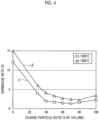
- Fig. 4 is a graph illustrating a shrinkage rate which changes in accordance with a coarse particle ratio.
- Fig. 5 is a graph illustrating a relative density which changes in accordance with the coarse particle ratio.
- the method for constructing an abradable coating according to Embodiment 1 is applied to a shroud which is provided in a gas turbine, such as a gas turbine generator or a gas turbine engine, as a construction object.
- a shroud 10 will be briefly described prior to the method for constructing an abradable coating.
- the shroud 10 is a casing provided to surround a radially outside of a plurality of rotor blades 11 that are arranged on a rotating shaft at predetermined intervals in a circumferential direction.
- a high-temperature working fluid such as combustion gas
- circulates in the shroud 10 and the plurality of rotor blades 11 rotate around the rotating shaft by the working fluid.
- the shroud 10 is a stationary member
- the plurality of rotor blades 11 are rotatable members that rotate around the rotating shaft.
- a clearance 15 is formed between the shroud 10 and each of the rotor blades 11 in a radial direction of the rotating shaft.
- the shroud 10 includes a shroud body (base material) 20, a thermal barrier coating layer (ceramic layer) 21, and an abradable coating layer 22.
- the shroud body 20 is made of, for example, a heat-resistant metallic material, such as a Ni-based superalloy, and a cooling flow passage 25 is formed in the shroud body 20.
- a cooling medium such as cooling air, circulates in the cooling flow passage 25 so as to cool the shroud body 20 that is heated by the high-temperature working fluid circulating in the shroud 10.
- the thermal barrier coating layer (TBC: thermal barrier coating) 21 is formed on the surface of the shroud body 20, that is, the surface of the shroud body 20 facing the rotor blades 11.
- the thermal barrier coating layer 21 is formed of a porous ceramic layer to inhibit heat from being input to the shroud body 20 from the high-temperature working fluid.
- a zirconia-based ceramic material which is an oxide-based ceramic material, is used for the thermal barrier coating layer 21, and ZrO 2 is used for the thermal barrier coating layer 21 in this embodiment.
- the porosity of the thermal barrier coating layer 21 is in the range of, for example, 5% to 15%, and is 10% in this embodiment.
- the thermal barrier coating layer 21 is evenly formed on the surface of the shroud body 20 as a layer having a uniform thickness by, for example, ceramic spraying (APS: atmospheric plasma spraying).
- the abradable coating layer 22 is formed on the surface of the thermal barrier coating layer 21.
- the abradable coating layer 22 is a seal material that is used to inhibit the working fluid from leaking from the clearance 15 formed between the shroud 10 and each rotor blade 11, and is subjected to free-cutting by each rotor blade 11. Since the abradable coating layer 22 is formed in the shape of a fin protruding from the thermal barrier coating layer 21, a predetermined pattern is formed on the thermal barrier coating layer 21. For example, a wavy fin is used as the pattern, but the shape of the pattern is not limited thereto and may be any shape that inhibits the working fluid from leaking.
- the same type of ceramic material as the thermal barrier coating layer 21 is used for the abradable coating layer 22. That is, a zirconia-based ceramic material is used for the abradable coating layer 22, and ZrO 2 is used for the abradable coating layer 22 in this embodiment.
- the abradable coating layer 22 is formed by laminating a plurality of sintered layers 35. The porosity of each sintered layer 35 is, for example, in the range of 10% to 40%, and is 20% in the present embodiment.
- the abradable coating layer 22 is formed on the surface of the thermal barrier coating layer 21 by a method for constructing an abradable coating which will be described later.
- the plurality of sintered layers 35 are two layers, and include a first sintered layer 35a which is a sintered layer 35 formed to be in contact with the surface of the thermal barrier coating layer 21, and a second sintered layer 35b which is a sintered layer 35 formed to be in contact with the first sintered layer 35a (refer to Fig. 2 ).
- the abradable coating layer 22 is configured with the two layers of sintered layers 35, but the number of layers may be more than two sintered layers 35.
- the shroud body 20 on which the thermal barrier coating layer 21 is constructed is applied as a base material 30 and the abradable coating layer 22 is formed on the surface of the thermal barrier coating layer 21.
- the shroud body 20 on which the thermal barrier coating layer 21 is constructed is applied as the base material 30.
- the abradable coating layer 22 is formed by laminating the two sintered layers 35.
- step S1 base material installing step.
- the base material 30 is installed such that the shroud body 20 is on the lower side and the thermal barrier coating layer 21 is on the upper side.
- a slurry layer 31 is formed on the surface of the thermal barrier coating layer 21 (base material 30) (step S2: slurry layer formation step).
- the slurry layer formation step S2 is repeated by the number of the sintered layers 35 to be laminated.
- the slurry layer formation step S2 the slurry layer 31 is formed following the surface of the base material 30, the slurry is applied on the surface of the base material 30, for example, by screen printing or the like, and accordingly, the slurry layer 31 is formed. Therefore, in the slurry layer formation step S2, a slurry layer 31 having a uniform thickness is formed even when the surface of the base material 30 is a curved surface.
- the slurry layer formation step S2 is performed two times in accordance with the two sintered layers 35. Specifically, in the slurry layer formation step S2, an initial (first) slurry layer formation step S2a which is the first slurry layer formation step S2 and a second slurry layer formation step S2b which is the last (second) slurry layer formation step S2 are performed. In the first slurry layer formation step S2a, a first slurry layer 31a which is the slurry layer 31 that is in contact with the surface of the base material 30 is formed. The first slurry layer 31a is partially sintered in a first sintering step which will be described later, and thus, the first slurry layer 31a becomes the first sintered layer 35a.
- a second slurry layer 31b which is the slurry layer 31 that is in contact with the first slurry layer 31a is formed.
- the second slurry layer 31b is partially sintered in the second sintering step which will be described later, and thus, the second slurry layer 31b becomes the second sintered layer 35b.
- the slurry which is used in the slurry layer formation step S2, will be described.
- the slurry contains ceramic particles, a solvent, a binder, and a dispersant.
- the ceramic particles include coarse particles and fine particles, and zirconia-based (for example, ZrO 2 ) ceramic particles are used as either particles.
- V1 volume of the coarse particles
- V2 volume of the fine particles
- a ratio (V1/V2) of the volume of the coarse particles to the volume of the fine particles satisfies the range of "50/50 ⁇ V1/V2 ⁇ 90/10".
- the average particle size of the coarse particles is in the range of 1 ⁇ m to 10 ⁇ m, and the coarse particles having an average particle size of 3.4 ⁇ m are used in Embodiment 1.
- the average particle size of the fine particles is in the range of 0.01 ⁇ m to 1 ⁇ m, and fine particles having an average particle size of 0.1 ⁇ m are used in this embodiment.
- water such as distilled water
- the solvent is mixed such that the volume concentration of the ceramic particles in the slurry is in the range of 20 to 60 vol%. Since water, which is harder to be volatilized than other solvents, such as alcohol, is used as the solvent in this embodiment, a change in the viscosity or the like of the slurry over time is inhibited.
- polyvinyl alcohol PVA
- the binder is mixed so that the percentage by mass of the binder is in the range of 1 to 10 wt% with respect to the mass of the ceramic particles.
- an ammonium salt of a polycarboxylic acid is used as the dispersant, and the dispersant is mixed so that the percentage by mass of the dispersant is in the range of 0.1 to 0.5 wt% with respect to the mass of the ceramic particles.
- the slurry used in the first slurry layer formation step S2a has a smaller proportion of the coarse particles and the greater proportion of the fine particles than that of the slurry used in the second slurry layer formation step S2b. This is for enhancing the adhesiveness of the first sintered layer 35a with respect to the surface of the base material 30.
- the slurry used in the second slurry layer formation step S2b has a greater proportion of the coarse particles and the smaller proportion of the fine particles than that of the slurry used in the first slurry layer formation step S2a. This is to enhance the free-cutting ability of the second sintered layer 35b by the rotor blades 11.
- FIG. 4 the horizontal axis represents the coarse particle ratio
- the vertical axis represents the shrinkage rate.
- a line L1 of the square ( ⁇ ) in white in Fig. 4 is a line indicating the shrinkage rate of the slurry when the sintering temperature of the slurry is 1200°C
- a line L2 of the triangle ( ⁇ ) in white in Fig. 4 is a line indicating the slurry shrinkage rate when the sintering temperature of the slurry is 1300°C.
- a line L3 of the square ( ⁇ ) in white in Fig. 5 is a line indicating the relative density of the slurry when the sintering temperature of the slurry is 1300°C
- a line L4 of the triangle ( ⁇ ) in white in Fig. 5 is a line indicating the relative density of the slurry when the sintering temperature of the slurry is 1200°C
- a line L5 of a ring ( ⁇ ) in white in Fig. 5 is a line indicating the relative density before the sintering of the slurry.
- the shrinkage rate of the slurry is 5% or more, separation from the surface of the base material 30 or the adjacent sintered layer 35 is likely to occur.
- the slurry has a coarse particle ratio of 40% or more and a shrinkage of less than 5% when the sintering is performed at 1300°C.
- the slurry has a range including the minimum shrinkage rate when the coarse particle ratio is between 50% and 80%.
- the slurry has a range including the maximum relative density when the coarse particle ratio between the sintering is between 50% and 80%.
- the relative density decreases when the coarse particle ratio becomes greater than 80%.
- any of the slurry used in the first slurry layer formation step S2a and the second slurry layer formation step S2b which has the coarse particle ratio of 50% or more is applied.
- the slurry used in the first slurry layer formation step S2a which has the coarse particle ratio of approximately 50% is applied, and the slurry used in the second slurry layer formation step S2b which has the coarse particle ratio of 70% to 80% is applied.
- step S3 sintering step.
- the slurry layer 31 is irradiated with laser Le, and the slurry layer 31 is sintered.
- the sintered layer 35 having a predetermined shape is formed by scanning the laser Le with a plurality of passes by a moving mechanism (not illustrated).
- the sintering step S3 is performed two times in accordance with the two sintered layers 35. Specifically, in the sintering step S3, an initial (first) sintering step S3a which is the first sintering step S3 and a second sintering step S3b which is the last (second) sintering step S3 are performed. In the first sintering step S3a, the first slurry layer 31a formed in the first slurry layer formation step S2a is irradiated with laser Le, the first slurry layer 31a is sintered, and accordingly, the first sintered layer 35a is formed.
- the second slurry layer 31b formed in the second slurry layer formation step S2b is irradiated with laser Le, the second slurry layer 31b is sintered, and accordingly, the second sintered layer 35b is formed.
- step S4 it is determined whether or not the sintered layer 35 has reached a predetermined number of layers (two layers in Embodiment 1) that configure the abradable coating layer 22 (step S4). In other words, in step S4, it is determined whether or not formation of the abradable coating layer 22 is completed. In a case where it is determined that the formation of the abradable coating layer 22 is not completed (step S4: No), the process moves to the slurry layer formation step S2 again, and then, the sintering step S3 is performed. In addition, the slurry layer formation step S2 and the sintering step S3 are repeated until reaching the predetermined number of layers.
- the second sintered layer 35b is formed such that the width (left-right direction in Fig. 2 ) in the orthogonal plane orthogonal to a laminating direction is narrower than the width of the first sintered layer 35a.
- a reference point for positioning is set on the base material 30, the movement of the laser Le is controlled based on the reference point, and accordingly, the first sintered layer 35a and the second sintered layer 35b are formed to be superimposed in the laminating direction.
- step S4 YES
- step S5 slurry removal step
- the base material 30 on which the abradable coating layer 22 is formed is washed with water to remove the non-sintered slurry.
- step S6 drying step.
- the solvent adhered to the base material 30 is volatilized through natural drying or drying by heating.
- step S7 inspection step.
- the inspection step S7 it is determined whether or not the shape of the fin of the abradable coating layer 22 has a predetermined shape by visual observation or image processing or the like.
- the inspection step S7 may be performed after the sintering step S3.
- the sintered layer 35 is formed by appropriately sintering the slurry layer 31, the sintered layer 35 is laminated by repeating the formation of the sintered layer 35, and accordingly, it is possible to form the abradable coating layer 22 on the surface of the base material 30.
- the surface of the base material 30 is a curved surface, a concave surface, or a convex surface, by using the slurry, it is possible to form the slurry layer 31 which becomes a uniform layer with respect to the surface of the base material 30.
- the abradable coating layer 22 having high free-cutting ability can be formed by simple steps, the construction of an abradable coating can be streamlined.
- the first sintered layer 35a after sintering the first slurry layer 31a can be formed to have high adhesiveness on the base material 30.
- the second sintered layer 35b after sintering the second slurry layer 31b can be formed to have high free-cutting ability.
- the laser Le it is possible to form the sintered layer 35 with high accuracy, and accordingly, it is possible to form the abradable coating layer 22 having the shape of the fin with high accuracy.
- the slurry removed by the solvent can be reused as slurry usable in the slurry layer formation step S2.
- the thermal barrier coating layer 21 and the abradable coating layer 22 can be firmly joined to each other.
- the thermal barrier coating layer 21 is porous, as the solvent contained in the slurry enters the pores of the thermal barrier coating layer 21, the ceramic particles are flocculated on an interface between the thermal barrier coating layer 21 and the slurry, and as the slurry layer is sintered in this state, the thermal barrier coating layer 21 and the abradable coating layer 22 are firmly joined to each other.
- a pore forming material may be contained in the slurry used in Embodiment 1.
- multiple pores can be formed in the abradable coating layer 22 by oxidation or volatilization of the pore forming material at the time of sintering the slurry layer 31, it is possible to further improve the free-cutting ability.
- the pore forming material at least one of a polymer-based material and a carbon-based material is contained, and other materials may be used as long as pores can be formed at the time of sintering the slurry layer 31.
- the abradable coating layer 22 is made of a zirconia-based ceramic material which is the same type of the thermal barrier coating layer 21.
- Fig. 6 is an explanatory view related to the method for constructing an abradable coating according to Embodiment 2.
- the method for constructing an abradable coating of Embodiment 2 has a different thickness in the laminating direction of the slurry layer 31 formed in the slurry layer formation step S2 of Embodiment 1.
- a focal position P of the laser Le irradiated in the sintering step S3 of Embodiment 1 is a surface of the abradable coating layer 22.
- the thickness of the first slurry layer 31a formed in the first slurry layer formation step S2a is formed to be thinner than the thickness of the second slurry layer 31b formed in the second slurry layer formation step S2b.
- the thickness of at least the first slurry layer 31a is formed to be thinner than that of the second slurry layer 31b. Therefore, the thickness of the first sintered layer 35a formed by sintering the first slurry layer 31a is also thinner than the thickness of the second sintered layer 35b formed by sintering the second slurry layer 31b.
- the thickness of the second sintered layer 35b is thicker than the thickness of the first sintered layer 35a.
- the focal position P of the laser Le is positioned on the surface of the abradable coating layer 22, that is, at the tip end portion in the protruding direction of the shape of the fin (laminating direction).
- the focal position P of the laser Le in the first sintering step S3a, is in an off-focus state being separated from the surface of the first slurry layer 31a, the first slurry layer 31a is irradiated with the laser Le, and the first slurry layer 31a is sintered.
- the second slurry layer 31b is irradiated with the laser Le, and the second slurry layer 31b is sintered.
- the first slurry layer 31a can be made thin, heating in the thickness direction (laminating direction) of the first slurry layer 31a in the first sintering step S3a can be appropriately performed, and the first sintered layer 35a can be appropriately formed.
- the first sintered layer 35a obtained by sintering the first slurry layer 31a can be made thin and the second sintered layer 35b obtained by sintering the second slurry layer 31b can be made thick, it is possible to increase the thickness of the second sintered layer 35b having high free-cutting ability in the thickness direction of the abradable coating layer 22 and to further improve the free-cutting ability.
- the focal position P of the laser Le is in an off-focus state being separated from the surface of the first slurry layer 31a.
- the focal position P of the laser Le is in an off-focus state being separated from the surface of the first slurry layer 31a.
- the first slurry layer 31a by irradiating the first slurry layer 31a with the laser Le in this state, it is possible to irradiate a wide region of the first slurry layer 31a with the laser Le, and thus, the first sintered layer 35a can be formed with a small number of passes.
Landscapes
- Chemical & Material Sciences (AREA)
- Engineering & Computer Science (AREA)
- Ceramic Engineering (AREA)
- Materials Engineering (AREA)
- Organic Chemistry (AREA)
- Mechanical Engineering (AREA)
- Chemical Kinetics & Catalysis (AREA)
- Structural Engineering (AREA)
- Combustion & Propulsion (AREA)
- Metallurgy (AREA)
- Manufacturing & Machinery (AREA)
- General Engineering & Computer Science (AREA)
- Inorganic Chemistry (AREA)
- Physics & Mathematics (AREA)
- Plasma & Fusion (AREA)
- General Chemical & Material Sciences (AREA)
- Life Sciences & Earth Sciences (AREA)
- Wood Science & Technology (AREA)
- Composite Materials (AREA)
- Turbine Rotor Nozzle Sealing (AREA)
- Application Of Or Painting With Fluid Materials (AREA)
Claims (8)
- Verfahren zum Aufbau einer abradierbaren Beschichtung auf einer Abdeckung (10), wobei die Abdeckung (10) in einer Gasturbine vorgesehen ist und einen Abdeckungskörper (20), eine Wärmebarrierenbeschichtungsschicht (21), die auf der Oberfläche des Abdeckungskörpers (20) ausgebildet ist, und eine abradierbare Beschichtungsschicht (22) umfasst, die auf der Oberfläche der Wärmebarrierenbeschichtungsschicht (21) ausgebildet ist und in Form einer Rippe ausgebildet ist, die von der Wärmebarrierenbeschichtungsschicht (21) vorsteht, um ein vorbestimmtes Muster von Vorsprüngen auf der Wärmebarrierenbeschichtungsschicht (21) zu bilden, wobei der Abdeckungskörper (20) und die Wärmebarrierenbeschichtungsschicht (21) zusammen ein Basismaterial (30) festlegen, das einer Laufschaufel (11) zugewandt ist,
dadurch gekennzeichnet, dass das Verfahren umfasst:einen ersten Suspensionsschicht-Bildungsschritt (S2a) zum Bilden einer ersten Suspensionsschicht (31a) auf einer Oberfläche des Basismaterials (30) durch Verwenden einer Suspension, die auf Zirkonoxid basierende Keramikpartikel, ein Lösungsmittel, ein Bindemittel und ein Dispergiermittel enthält;einen ersten Sinterschritt (S3a) zum Bilden einer ersten Sinterschicht (35a), die ein Abschnitt der abradierbare Beschichtungsschicht (22) sein wird, durch Sintern der ersten Suspensionsschicht (31a), die auf der Oberfläche des Basismaterials (30) gebildet wird, wobei die erste Sinterschicht (35a) durch Bestrahlen der ersten Suspensionsschicht (31a) mit einem Laser (Le) und Scannen des Lasers (Le) mit einer Mehrzahl von Durchgängen unter Verwendung eines Bewegungsmechanismus gebildet wird;einen zweiten Suspensionsschicht-Bildungsschritt (S2b) zum Bilden einer zweiten Suspensionsschicht (31b) auf einer Oberfläche der ersten Suspensionsschicht (31a) unter Verwendung einer Suspension, die auf Zirkonoxid basierende Keramikpartikel, ein Lösungsmittel, ein Bindemittel und ein Dispergiermittel enthält;einen zweiten Sinterschritt (S3b) zum Bilden einer zweiten Sinterschicht (35b), die ein weiterer Abschnitt der abradierbare Beschichtungsschicht (22) ist, durch Sintern der zweiten Suspensionsschicht (31b), die auf der Oberfläche der ersten Sinterschicht (35a) gebildet, wobei die zweite Sinterschicht (35b) durch Bestrahlen der zweiten Suspensionsschicht (31b) mit einem Laser (Le) und Scannen des Lasers (Le) mit einer Mehrzahl von Durchgängen unter Verwendung eines Bewegungsmechanismus gebildet wird;einen Suspensionsentfernungsschritt (S5) zum Entfernen einer nicht gesinterten Suspension der ersten Suspensionsschicht (31a) und der zweiten Suspensionsschicht (31b) nach dem Bilden der abradierbare Beschichtungsschicht (22), in der eine Mehrzahl der Sinterschichten (35a, 35b) auf der Oberfläche des Basismaterials (30) geschichtet sind; undeinen Trocknungsschritt (S6) zum Trocknen des Basismaterials (30), auf das die abradierbare Beschichtungsschicht (22) aufgebracht ist, nach dem Entfernen der nicht gesinterten Supension,wobei die zweite Sinterschicht (35b) derart ausgebildet ist, dass die Breite der zweiten Sinterschicht (35b) in der orthogonalen Ebene orthogonal zu einer Laminierungsrichtung schmaler ist als die Breite der ersten Sinterschicht (35a), während die erste Sinterschicht (35a) und die zweite Sinterschicht (35b) so ausgebildet sind, dass sie in Laminierungsrichtung übereinander liegen, wobei die Zirkoniumdioxid-basierten Keramikpartikel grobe Zirkoniumdioxid-basierte Keramikpartikel mit einer durchschnittlichen Partikelgröße von 1 bis 10 µm und feine Zirkoniumdioxid-basierte Keramikpartikel mit einer durchschnittlichen Partikelgröße von 0,01 bis 1 µm umfassen, wobei die in der ersten Suspensionsschicht (31a) verwendete Suspension ein Verhältnis von groben, auf Zirkonoxid basierenden Keramikpartikeln von 50 % aufweist und die in der zweiten Suspensionsschicht (31b) verwendete Suspension ein Verhältnis von groben, auf Zirkonoxid basierenden Keramikpartikeln von 70 bis 80 % aufweist, wobei das Verhältnis der groben, auf Zirkonoxid basierenden Keramikpartikel als der Anteil der groben, auf Zirkonoxid basierenden Keramikpartikel bezüglich der feinen, auf Zirkonoxid basierenden Keramikpartikel festgelegt ist und wobei die abradierbare Beschichtungsschicht (22) und die Wärmebarrierenbeschichtungsschicht (21) aus dem gleichen Typ von Zirkonoxid basierendem Keramikmaterial gebildet sind. - Das Verfahren zum Aufbau einer abradierbaren Beschichtung gemäß Anspruch 1, wobei die Dicke der ersten Suspensionsschicht (31a) dünner als die der zweiten Suspensionsschicht (31b) ausgebildet ist.
- Das Verfahren zum Aufbau einer abradierbaren Beschichtung gemäß Anspruch 1 oder 2, wobei in dem ersten Sinterschritt (S3a) die erste Suspensionsschicht (31a) mit einem Laser (Le) bestrahlt wird, wobei eine Fokusposition (P) des Lasers (Le) als die Oberfläche der abradierbaren Beschichtungsschicht (22) eingestellt wird, und in einem defokussierten Zustand, in dem die Fokussierungsposition (P) des Lasers (Le) von der Oberfläche der ersten Suspensionsschicht (31a) getrennt ist, die erste Suspensionsschicht (31a) mit dem Laser (Le) bestrahlt wird und die erste Suspensionsschicht (31a) gesintert wird.
- Das Verfahren zum Aufbau einer abradierbaren Beschichtung gemäß einem der Ansprüche 1 bis 3, wobei in dem Schritt des Entfernens der Suspension (S5) unter Verwendung des Lösungsmittels die nicht gesinterte Suspension entfernt wird.
- Das Verfahren zum Aufbau einer abradierbaren Beschichtung gemäß einem der Ansprüche 1 bis 4, wobei die Suspension ferner ein porenbildendes Material enthält.
- Das Verfahren zum Aufbau einer abradierbaren Beschichtung gemäß Anspruch 5, wobei das porenbildende Material mindestens eines von einem kohlenstoffbasierten Material und einem polymerbasierten Material enthält.
- Das Verfahren zum Aufbau einer abradierbaren Beschichtung gemäß einem der Ansprüche 1 bis 6, ferner mit einem Inspektionsschritt (S7) zum Inspizieren der abradierbaren Beschichtungsschicht (22), die auf dem Basismaterial (30) nach dem Schritt des Entfernens der Suspension (S5) gebildet wird.
- Das Verfahren zum Aufbau einer abradierbaren Beschichtung gemäß einem der Ansprüche 1 bis 7, wobei das Lösungsmittel Wasser ist, das derart beigemischt wird, dass die Konzentration der auf Zirkonoxid basierenden Keramikpartikel in der Suspension im Bereich von 20 bis 60 Vol.-% liegt.
Applications Claiming Priority (2)
| Application Number | Priority Date | Filing Date | Title |
|---|---|---|---|
| JP2016157802A JP6896385B2 (ja) | 2016-08-10 | 2016-08-10 | アブレイダブルコーティングの施工方法 |
| PCT/JP2017/020921 WO2018029957A1 (ja) | 2016-08-10 | 2017-06-06 | アブレイダブルコーティングの施工方法及びシュラウド |
Publications (3)
| Publication Number | Publication Date |
|---|---|
| EP3427843A1 EP3427843A1 (de) | 2019-01-16 |
| EP3427843A4 EP3427843A4 (de) | 2019-04-17 |
| EP3427843B1 true EP3427843B1 (de) | 2024-12-04 |
Family
ID=61162588
Family Applications (1)
| Application Number | Title | Priority Date | Filing Date |
|---|---|---|---|
| EP17839032.4A Active EP3427843B1 (de) | 2016-08-10 | 2017-06-06 | Verfahren zur herstellung einer abreibbaren beschichtung und verkleidung |
Country Status (6)
| Country | Link |
|---|---|
| US (1) | US10994301B2 (de) |
| EP (1) | EP3427843B1 (de) |
| JP (1) | JP6896385B2 (de) |
| CA (1) | CA3019632C (de) |
| ES (1) | ES3002335T3 (de) |
| WO (1) | WO2018029957A1 (de) |
Families Citing this family (1)
| Publication number | Priority date | Publication date | Assignee | Title |
|---|---|---|---|---|
| EP3795800B1 (de) * | 2019-09-20 | 2023-03-01 | Raytheon Technologies Corporation | Abgedichtetes cmc-turbinengehäuse |
Family Cites Families (18)
| Publication number | Priority date | Publication date | Assignee | Title |
|---|---|---|---|---|
| US5156697A (en) | 1989-09-05 | 1992-10-20 | Board Of Regents, The University Of Texas System | Selective laser sintering of parts by compound formation of precursor powders |
| JPH03214440A (ja) * | 1990-01-19 | 1991-09-19 | Nippon Sheet Glass Co Ltd | 光ディスク基板の製造方法 |
| US6057047A (en) * | 1997-11-18 | 2000-05-02 | United Technologies Corporation | Ceramic coatings containing layered porosity |
| EP1111195B2 (de) | 1999-12-20 | 2013-05-01 | Sulzer Metco AG | Profilierte, als Anstreifschicht verwendete Oberfläche in Strömungsmaschinen |
| TWI228114B (en) * | 1999-12-24 | 2005-02-21 | Nat Science Council | Method and equipment for making ceramic work piece |
| US6660405B2 (en) * | 2001-05-24 | 2003-12-09 | General Electric Co. | High temperature abradable coating for turbine shrouds without bucket tipping |
| US20050003172A1 (en) | 2002-12-17 | 2005-01-06 | General Electric Company | 7FAstage 1 abradable coatings and method for making same |
| US6916529B2 (en) * | 2003-01-09 | 2005-07-12 | General Electric Company | High temperature, oxidation-resistant abradable coatings containing microballoons and method for applying same |
| US8575513B2 (en) * | 2006-07-06 | 2013-11-05 | Siemens Energy, Inc. | Rapid prototyping of ceramic articles |
| JP2010151267A (ja) * | 2008-12-26 | 2010-07-08 | Hitachi Ltd | シール構造、およびこれを用いたガスタービン |
| US10508059B2 (en) | 2013-12-12 | 2019-12-17 | General Electric Company | Method of depositing abradable coatings under polymer gels |
| EP3080056B1 (de) * | 2013-12-12 | 2018-10-17 | General Electric Company | Verfahren zur abscheidung abreibbarer beschichtungen unter polymergelen |
| US9249680B2 (en) * | 2014-02-25 | 2016-02-02 | Siemens Energy, Inc. | Turbine abradable layer with asymmetric ridges or grooves |
| EP3111051A1 (de) * | 2014-02-25 | 2017-01-04 | Siemens Aktiengesellschaft | Turbinenringsegment mit abreibbarer schicht mit zusammengesetztem winkel, asymmetrischem oberflächendichtefirst und rillenmuster |
| US20150354393A1 (en) * | 2014-06-10 | 2015-12-10 | General Electric Company | Methods of manufacturing a shroud abradable coating |
| US20170304894A1 (en) * | 2014-11-10 | 2017-10-26 | Velo3D, Inc. | Printing three-dimensional objects using beam array |
| US20160265367A1 (en) | 2014-12-22 | 2016-09-15 | General Electric Company | Environmental barrier coating with abradable coating for ceramic matrix composites |
| JP6632407B2 (ja) | 2016-02-04 | 2020-01-22 | 三菱重工航空エンジン株式会社 | アブレイダブルコーティングの施工方法 |
-
2016
- 2016-08-10 JP JP2016157802A patent/JP6896385B2/ja active Active
-
2017
- 2017-06-06 EP EP17839032.4A patent/EP3427843B1/de active Active
- 2017-06-06 US US16/092,247 patent/US10994301B2/en active Active
- 2017-06-06 WO PCT/JP2017/020921 patent/WO2018029957A1/ja not_active Ceased
- 2017-06-06 CA CA3019632A patent/CA3019632C/en active Active
- 2017-06-06 ES ES17839032T patent/ES3002335T3/es active Active
Non-Patent Citations (1)
| Title |
|---|
| XIAOYONG TIAN ET AL: "Rapid prototyping of porcelain products by layer‐wise slurry deposition (LSD) and direct laser sintering", RAPID PROTOTYPING JOURNAL, vol. 18, no. 5, 27 July 2012 (2012-07-27), GB, pages 362 - 373, XP055295787, ISSN: 1355-2546, DOI: 10.1108/13552541211250364 * |
Also Published As
| Publication number | Publication date |
|---|---|
| JP2018023939A (ja) | 2018-02-15 |
| EP3427843A4 (de) | 2019-04-17 |
| JP6896385B2 (ja) | 2021-06-30 |
| EP3427843A1 (de) | 2019-01-16 |
| WO2018029957A1 (ja) | 2018-02-15 |
| US20190143368A1 (en) | 2019-05-16 |
| CA3019632A1 (en) | 2018-02-15 |
| ES3002335T3 (en) | 2025-03-06 |
| US10994301B2 (en) | 2021-05-04 |
| CA3019632C (en) | 2021-07-20 |
Similar Documents
| Publication | Publication Date | Title |
|---|---|---|
| US8668442B2 (en) | Turbine nozzles and methods of manufacturing the same | |
| JP6339704B2 (ja) | レーザーを用いて粉末を固形化することによって物体を製造する方法 | |
| RU2330162C2 (ru) | Высокотемпературная слоистая система для теплоотвода и способ для ее изготовления (варианты) | |
| US20170081250A1 (en) | Method of forming a thermal barrier coating having a porosity architecture using additive manufacturing | |
| CN107116335B (zh) | 制造和修理燃气涡轮构件的系统和方法 | |
| JP2016006320A (ja) | アブレイダブル皮膜 | |
| CN105220103A (zh) | 制造护罩可磨耗涂层的方法 | |
| CN104507602B (zh) | 由具有低表面粗糙度的材料制成的耐磨涂层 | |
| US20190389171A1 (en) | Adaptive microtexturing of a composite material | |
| US20200247003A1 (en) | Methods and systems for three-dimensional printing of ceramic fiber composite structures | |
| TW201945153A (zh) | 模具鎖修復 | |
| US20190249567A1 (en) | Gas turbine hot part and gas turbine | |
| Nachum et al. | Additive manufacturing of ceramics: Stereolithography versus binder jetting | |
| KR102486067B1 (ko) | 차열 코팅, 터빈 부재, 가스 터빈 및 차열 코팅의 제조 방법 | |
| CA3019632C (en) | Method for constructing abradable coating, and shroud | |
| US9845685B2 (en) | Process for producing a run-in coating | |
| JP7045236B2 (ja) | 遮熱コーティング、タービン部材及びガスタービン | |
| EP3369487B1 (de) | Mantel und verfahren zur implementierung einer abreibbaren beschichtung | |
| US10138739B2 (en) | Part consisting of a ceramic material, comprising a base and a wall | |
| JP2018087115A (ja) | セラミックス基複合材の製造方法 | |
| US10953495B2 (en) | Building platform for additive manufacturing, and method | |
| JP2019157216A (ja) | セラミックコーティング、タービン部材、ガスタービン及びセラミックコーティングの製造方法 | |
| CN114466949B (zh) | 陶瓷涂层、涡轮构件及燃气轮机 | |
| Zheng | A Densified Binder-jet Printed Powder System Via Viscous-Rearrangement Assisted Sintering |
Legal Events
| Date | Code | Title | Description |
|---|---|---|---|
| STAA | Information on the status of an ep patent application or granted ep patent |
Free format text: STATUS: THE INTERNATIONAL PUBLICATION HAS BEEN MADE |
|
| PUAI | Public reference made under article 153(3) epc to a published international application that has entered the european phase |
Free format text: ORIGINAL CODE: 0009012 |
|
| STAA | Information on the status of an ep patent application or granted ep patent |
Free format text: STATUS: REQUEST FOR EXAMINATION WAS MADE |
|
| 17P | Request for examination filed |
Effective date: 20181010 |
|
| AK | Designated contracting states |
Kind code of ref document: A1 Designated state(s): AL AT BE BG CH CY CZ DE DK EE ES FI FR GB GR HR HU IE IS IT LI LT LU LV MC MK MT NL NO PL PT RO RS SE SI SK SM TR |
|
| AX | Request for extension of the european patent |
Extension state: BA ME |
|
| A4 | Supplementary search report drawn up and despatched |
Effective date: 20190319 |
|
| RIC1 | Information provided on ipc code assigned before grant |
Ipc: F01D 25/00 20060101ALI20190313BHEP Ipc: B33Y 10/00 20150101ALI20190313BHEP Ipc: B05D 3/06 20060101ALI20190313BHEP Ipc: C23C 4/10 20160101ALI20190313BHEP Ipc: C23C 24/08 20060101ALI20190313BHEP Ipc: C04B 35/117 20060101ALI20190313BHEP Ipc: C04B 41/87 20060101ALI20190313BHEP Ipc: C04B 38/06 20060101ALI20190313BHEP Ipc: C23C 26/00 20060101ALI20190313BHEP Ipc: B05D 3/02 20060101ALI20190313BHEP Ipc: C23C 28/04 20060101ALI20190313BHEP Ipc: F02C 7/24 20060101ALI20190313BHEP Ipc: F02C 7/00 20060101ALI20190313BHEP Ipc: F02C 7/28 20060101ALI20190313BHEP Ipc: C23C 28/00 20060101ALI20190313BHEP Ipc: B05D 1/38 20060101AFI20190313BHEP Ipc: C04B 41/89 20060101ALI20190313BHEP Ipc: B05D 7/24 20060101ALI20190313BHEP Ipc: F01D 11/12 20060101ALI20190313BHEP Ipc: B05D 3/10 20060101ALI20190313BHEP |
|
| DAV | Request for validation of the european patent (deleted) | ||
| DAX | Request for extension of the european patent (deleted) | ||
| STAA | Information on the status of an ep patent application or granted ep patent |
Free format text: STATUS: EXAMINATION IS IN PROGRESS |
|
| 17Q | First examination report despatched |
Effective date: 20191216 |
|
| REG | Reference to a national code |
Free format text: PREVIOUS MAIN CLASS: B05D0001380000 Ref country code: DE Ref legal event code: R079 Ref document number: 602017086589 Country of ref document: DE Free format text: PREVIOUS MAIN CLASS: B05D0001380000 Ipc: C04B0041870000 |
|
| RIC1 | Information provided on ipc code assigned before grant |
Ipc: C04B 35/486 20060101ALI20240520BHEP Ipc: C04B 35/195 20060101ALI20240520BHEP Ipc: C23C 24/08 20060101ALI20240520BHEP Ipc: C23C 28/04 20060101ALI20240520BHEP Ipc: B33Y 10/00 20150101ALI20240520BHEP Ipc: C04B 38/06 20060101ALI20240520BHEP Ipc: C04B 35/16 20060101ALI20240520BHEP Ipc: C04B 35/117 20060101ALI20240520BHEP Ipc: C04B 35/111 20060101ALI20240520BHEP Ipc: C04B 41/89 20060101ALI20240520BHEP Ipc: C04B 41/87 20060101AFI20240520BHEP |
|
| GRAP | Despatch of communication of intention to grant a patent |
Free format text: ORIGINAL CODE: EPIDOSNIGR1 |
|
| STAA | Information on the status of an ep patent application or granted ep patent |
Free format text: STATUS: GRANT OF PATENT IS INTENDED |
|
| INTG | Intention to grant announced |
Effective date: 20240827 |
|
| GRAS | Grant fee paid |
Free format text: ORIGINAL CODE: EPIDOSNIGR3 |
|
| GRAA | (expected) grant |
Free format text: ORIGINAL CODE: 0009210 |
|
| STAA | Information on the status of an ep patent application or granted ep patent |
Free format text: STATUS: THE PATENT HAS BEEN GRANTED |
|
| AK | Designated contracting states |
Kind code of ref document: B1 Designated state(s): AL AT BE BG CH CY CZ DE DK EE ES FI FR GB GR HR HU IE IS IT LI LT LU LV MC MK MT NL NO PL PT RO RS SE SI SK SM TR |
|
| REG | Reference to a national code |
Ref country code: GB Ref legal event code: FG4D |
|
| REG | Reference to a national code |
Ref country code: CH Ref legal event code: EP |
|
| REG | Reference to a national code |
Ref country code: DE Ref legal event code: R096 Ref document number: 602017086589 Country of ref document: DE |
|
| REG | Reference to a national code |
Ref country code: IE Ref legal event code: FG4D |
|
| REG | Reference to a national code |
Ref country code: ES Ref legal event code: FG2A Ref document number: 3002335 Country of ref document: ES Kind code of ref document: T3 Effective date: 20250306 |
|
| REG | Reference to a national code |
Ref country code: LT Ref legal event code: MG9D |
|
| REG | Reference to a national code |
Ref country code: NL Ref legal event code: MP Effective date: 20241204 |
|
| PG25 | Lapsed in a contracting state [announced via postgrant information from national office to epo] |
Ref country code: HR Free format text: LAPSE BECAUSE OF FAILURE TO SUBMIT A TRANSLATION OF THE DESCRIPTION OR TO PAY THE FEE WITHIN THE PRESCRIBED TIME-LIMIT Effective date: 20241204 |
|
| PG25 | Lapsed in a contracting state [announced via postgrant information from national office to epo] |
Ref country code: FI Free format text: LAPSE BECAUSE OF FAILURE TO SUBMIT A TRANSLATION OF THE DESCRIPTION OR TO PAY THE FEE WITHIN THE PRESCRIBED TIME-LIMIT Effective date: 20241204 |
|
| PG25 | Lapsed in a contracting state [announced via postgrant information from national office to epo] |
Ref country code: BG Free format text: LAPSE BECAUSE OF FAILURE TO SUBMIT A TRANSLATION OF THE DESCRIPTION OR TO PAY THE FEE WITHIN THE PRESCRIBED TIME-LIMIT Effective date: 20241204 |
|
| PG25 | Lapsed in a contracting state [announced via postgrant information from national office to epo] |
Ref country code: NO Free format text: LAPSE BECAUSE OF FAILURE TO SUBMIT A TRANSLATION OF THE DESCRIPTION OR TO PAY THE FEE WITHIN THE PRESCRIBED TIME-LIMIT Effective date: 20250304 |
|
| PG25 | Lapsed in a contracting state [announced via postgrant information from national office to epo] |
Ref country code: GR Free format text: LAPSE BECAUSE OF FAILURE TO SUBMIT A TRANSLATION OF THE DESCRIPTION OR TO PAY THE FEE WITHIN THE PRESCRIBED TIME-LIMIT Effective date: 20250305 Ref country code: LV Free format text: LAPSE BECAUSE OF FAILURE TO SUBMIT A TRANSLATION OF THE DESCRIPTION OR TO PAY THE FEE WITHIN THE PRESCRIBED TIME-LIMIT Effective date: 20241204 |
|
| PG25 | Lapsed in a contracting state [announced via postgrant information from national office to epo] |
Ref country code: RS Free format text: LAPSE BECAUSE OF FAILURE TO SUBMIT A TRANSLATION OF THE DESCRIPTION OR TO PAY THE FEE WITHIN THE PRESCRIBED TIME-LIMIT Effective date: 20250304 |
|
| PG25 | Lapsed in a contracting state [announced via postgrant information from national office to epo] |
Ref country code: NL Free format text: LAPSE BECAUSE OF FAILURE TO SUBMIT A TRANSLATION OF THE DESCRIPTION OR TO PAY THE FEE WITHIN THE PRESCRIBED TIME-LIMIT Effective date: 20241204 |
|
| REG | Reference to a national code |
Ref country code: AT Ref legal event code: MK05 Ref document number: 1748032 Country of ref document: AT Kind code of ref document: T Effective date: 20241204 |
|
| PG25 | Lapsed in a contracting state [announced via postgrant information from national office to epo] |
Ref country code: SM Free format text: LAPSE BECAUSE OF FAILURE TO SUBMIT A TRANSLATION OF THE DESCRIPTION OR TO PAY THE FEE WITHIN THE PRESCRIBED TIME-LIMIT Effective date: 20241204 |
|
| PG25 | Lapsed in a contracting state [announced via postgrant information from national office to epo] |
Ref country code: PL Free format text: LAPSE BECAUSE OF FAILURE TO SUBMIT A TRANSLATION OF THE DESCRIPTION OR TO PAY THE FEE WITHIN THE PRESCRIBED TIME-LIMIT Effective date: 20241204 |
|
| PGFP | Annual fee paid to national office [announced via postgrant information from national office to epo] |
Ref country code: DE Payment date: 20250429 Year of fee payment: 9 |
|
| PGFP | Annual fee paid to national office [announced via postgrant information from national office to epo] |
Ref country code: GB Payment date: 20250501 Year of fee payment: 9 |
|
| PG25 | Lapsed in a contracting state [announced via postgrant information from national office to epo] |
Ref country code: IS Free format text: LAPSE BECAUSE OF FAILURE TO SUBMIT A TRANSLATION OF THE DESCRIPTION OR TO PAY THE FEE WITHIN THE PRESCRIBED TIME-LIMIT Effective date: 20250404 |
|
| PG25 | Lapsed in a contracting state [announced via postgrant information from national office to epo] |
Ref country code: PT Free format text: LAPSE BECAUSE OF FAILURE TO SUBMIT A TRANSLATION OF THE DESCRIPTION OR TO PAY THE FEE WITHIN THE PRESCRIBED TIME-LIMIT Effective date: 20250404 |
|
| PG25 | Lapsed in a contracting state [announced via postgrant information from national office to epo] |
Ref country code: EE Free format text: LAPSE BECAUSE OF FAILURE TO SUBMIT A TRANSLATION OF THE DESCRIPTION OR TO PAY THE FEE WITHIN THE PRESCRIBED TIME-LIMIT Effective date: 20241204 |
|
| PGFP | Annual fee paid to national office [announced via postgrant information from national office to epo] |
Ref country code: FR Payment date: 20250508 Year of fee payment: 9 |
|
| PG25 | Lapsed in a contracting state [announced via postgrant information from national office to epo] |
Ref country code: AT Free format text: LAPSE BECAUSE OF FAILURE TO SUBMIT A TRANSLATION OF THE DESCRIPTION OR TO PAY THE FEE WITHIN THE PRESCRIBED TIME-LIMIT Effective date: 20241204 Ref country code: RO Free format text: LAPSE BECAUSE OF FAILURE TO SUBMIT A TRANSLATION OF THE DESCRIPTION OR TO PAY THE FEE WITHIN THE PRESCRIBED TIME-LIMIT Effective date: 20241204 |
|
| PG25 | Lapsed in a contracting state [announced via postgrant information from national office to epo] |
Ref country code: SK Free format text: LAPSE BECAUSE OF FAILURE TO SUBMIT A TRANSLATION OF THE DESCRIPTION OR TO PAY THE FEE WITHIN THE PRESCRIBED TIME-LIMIT Effective date: 20241204 |
|
| PG25 | Lapsed in a contracting state [announced via postgrant information from national office to epo] |
Ref country code: CZ Free format text: LAPSE BECAUSE OF FAILURE TO SUBMIT A TRANSLATION OF THE DESCRIPTION OR TO PAY THE FEE WITHIN THE PRESCRIBED TIME-LIMIT Effective date: 20241204 |
|
| PG25 | Lapsed in a contracting state [announced via postgrant information from national office to epo] |
Ref country code: IT Free format text: LAPSE BECAUSE OF FAILURE TO SUBMIT A TRANSLATION OF THE DESCRIPTION OR TO PAY THE FEE WITHIN THE PRESCRIBED TIME-LIMIT Effective date: 20241204 |
|
| REG | Reference to a national code |
Ref country code: DE Ref legal event code: R097 Ref document number: 602017086589 Country of ref document: DE |
|
| PG25 | Lapsed in a contracting state [announced via postgrant information from national office to epo] |
Ref country code: SE Free format text: LAPSE BECAUSE OF FAILURE TO SUBMIT A TRANSLATION OF THE DESCRIPTION OR TO PAY THE FEE WITHIN THE PRESCRIBED TIME-LIMIT Effective date: 20241204 |
|
| PGFP | Annual fee paid to national office [announced via postgrant information from national office to epo] |
Ref country code: ES Payment date: 20250701 Year of fee payment: 9 |
|
| PG25 | Lapsed in a contracting state [announced via postgrant information from national office to epo] |
Ref country code: DK Free format text: LAPSE BECAUSE OF FAILURE TO SUBMIT A TRANSLATION OF THE DESCRIPTION OR TO PAY THE FEE WITHIN THE PRESCRIBED TIME-LIMIT Effective date: 20241204 |
|
| PLBE | No opposition filed within time limit |
Free format text: ORIGINAL CODE: 0009261 |
|
| STAA | Information on the status of an ep patent application or granted ep patent |
Free format text: STATUS: NO OPPOSITION FILED WITHIN TIME LIMIT |
|
| REG | Reference to a national code |
Ref country code: CH Ref legal event code: L10 Free format text: ST27 STATUS EVENT CODE: U-0-0-L10-L00 (AS PROVIDED BY THE NATIONAL OFFICE) Effective date: 20251015 |
|
| 26N | No opposition filed |
Effective date: 20250905 |
|
| REG | Reference to a national code |
Ref country code: CH Ref legal event code: H13 Free format text: ST27 STATUS EVENT CODE: U-0-0-H10-H13 (AS PROVIDED BY THE NATIONAL OFFICE) Effective date: 20260127 |
|
| PG25 | Lapsed in a contracting state [announced via postgrant information from national office to epo] |
Ref country code: MC Free format text: LAPSE BECAUSE OF FAILURE TO SUBMIT A TRANSLATION OF THE DESCRIPTION OR TO PAY THE FEE WITHIN THE PRESCRIBED TIME-LIMIT Effective date: 20241204 |
|
| PG25 | Lapsed in a contracting state [announced via postgrant information from national office to epo] |
Ref country code: LU Free format text: LAPSE BECAUSE OF NON-PAYMENT OF DUE FEES Effective date: 20250606 |
|
| REG | Reference to a national code |
Ref country code: BE Ref legal event code: MM Effective date: 20250630 |
|
| PG25 | Lapsed in a contracting state [announced via postgrant information from national office to epo] |
Ref country code: IE Free format text: LAPSE BECAUSE OF NON-PAYMENT OF DUE FEES Effective date: 20250606 |
|
| PG25 | Lapsed in a contracting state [announced via postgrant information from national office to epo] |
Ref country code: BE Free format text: LAPSE BECAUSE OF NON-PAYMENT OF DUE FEES Effective date: 20250630 |
|
| PG25 | Lapsed in a contracting state [announced via postgrant information from national office to epo] |
Ref country code: CH Free format text: LAPSE BECAUSE OF NON-PAYMENT OF DUE FEES Effective date: 20250630 |