EP3427840A1 - Distributeur de liquide - Google Patents
Distributeur de liquide Download PDFInfo
- Publication number
- EP3427840A1 EP3427840A1 EP17181288.6A EP17181288A EP3427840A1 EP 3427840 A1 EP3427840 A1 EP 3427840A1 EP 17181288 A EP17181288 A EP 17181288A EP 3427840 A1 EP3427840 A1 EP 3427840A1
- Authority
- EP
- European Patent Office
- Prior art keywords
- valve
- liquid
- discharge head
- pumping chamber
- active member
- Prior art date
- Legal status (The legal status is an assumption and is not a legal conclusion. Google has not performed a legal analysis and makes no representation as to the accuracy of the status listed.)
- Granted
Links
- 239000007788 liquid Substances 0.000 title claims abstract description 90
- 238000005086 pumping Methods 0.000 claims abstract description 80
- 230000001419 dependent effect Effects 0.000 claims abstract description 13
- 238000009423 ventilation Methods 0.000 claims abstract description 10
- 239000002537 cosmetic Substances 0.000 claims abstract description 9
- 238000007599 discharging Methods 0.000 claims abstract description 5
- 239000006210 lotion Substances 0.000 claims description 5
- 238000013022 venting Methods 0.000 claims description 5
- 239000007787 solid Substances 0.000 claims description 4
- 230000002093 peripheral effect Effects 0.000 claims description 3
- 239000000499 gel Substances 0.000 claims description 2
- 239000002453 shampoo Substances 0.000 claims description 2
- 239000000344 soap Substances 0.000 claims description 2
- 238000013461 design Methods 0.000 description 12
- 230000007423 decrease Effects 0.000 description 7
- 230000008878 coupling Effects 0.000 description 5
- 238000010168 coupling process Methods 0.000 description 5
- 238000005859 coupling reaction Methods 0.000 description 5
- 230000000694 effects Effects 0.000 description 5
- 239000012530 fluid Substances 0.000 description 5
- 230000009467 reduction Effects 0.000 description 4
- 230000008901 benefit Effects 0.000 description 3
- 230000000881 depressing effect Effects 0.000 description 3
- 238000006073 displacement reaction Methods 0.000 description 2
- 238000000034 method Methods 0.000 description 2
- 238000007789 sealing Methods 0.000 description 2
- 230000009471 action Effects 0.000 description 1
- 238000005273 aeration Methods 0.000 description 1
- 238000013459 approach Methods 0.000 description 1
- 230000008859 change Effects 0.000 description 1
- 238000006243 chemical reaction Methods 0.000 description 1
- 238000010276 construction Methods 0.000 description 1
- 239000000356 contaminant Substances 0.000 description 1
- 239000008341 cosmetic lotion Substances 0.000 description 1
- 230000003247 decreasing effect Effects 0.000 description 1
- 239000013013 elastic material Substances 0.000 description 1
- 229920001971 elastomer Polymers 0.000 description 1
- 239000000806 elastomer Substances 0.000 description 1
- 230000001815 facial effect Effects 0.000 description 1
- 239000008187 granular material Substances 0.000 description 1
- 238000004519 manufacturing process Methods 0.000 description 1
- 230000013011 mating Effects 0.000 description 1
- 230000035515 penetration Effects 0.000 description 1
- 230000008092 positive effect Effects 0.000 description 1
- 230000037452 priming Effects 0.000 description 1
- 230000008569 process Effects 0.000 description 1
- 238000007493 shaping process Methods 0.000 description 1
- 238000012546 transfer Methods 0.000 description 1
Images

Classifications
-
- B—PERFORMING OPERATIONS; TRANSPORTING
- B05—SPRAYING OR ATOMISING IN GENERAL; APPLYING FLUENT MATERIALS TO SURFACES, IN GENERAL
- B05B—SPRAYING APPARATUS; ATOMISING APPARATUS; NOZZLES
- B05B11/00—Single-unit hand-held apparatus in which flow of contents is produced by the muscular force of the operator at the moment of use
- B05B11/0005—Components or details
- B05B11/0037—Containers
- B05B11/0039—Containers associated with means for compensating the pressure difference between the ambient pressure and the pressure inside the container, e.g. pressure relief means
- B05B11/0044—Containers associated with means for compensating the pressure difference between the ambient pressure and the pressure inside the container, e.g. pressure relief means compensating underpressure by ingress of atmospheric air into the container, i.e. with venting means
-
- A—HUMAN NECESSITIES
- A45—HAND OR TRAVELLING ARTICLES
- A45D—HAIRDRESSING OR SHAVING EQUIPMENT; EQUIPMENT FOR COSMETICS OR COSMETIC TREATMENTS, e.g. FOR MANICURING OR PEDICURING
- A45D34/00—Containers or accessories specially adapted for handling liquid toiletry or cosmetic substances, e.g. perfumes
-
- B—PERFORMING OPERATIONS; TRANSPORTING
- B05—SPRAYING OR ATOMISING IN GENERAL; APPLYING FLUENT MATERIALS TO SURFACES, IN GENERAL
- B05B—SPRAYING APPARATUS; ATOMISING APPARATUS; NOZZLES
- B05B11/00—Single-unit hand-held apparatus in which flow of contents is produced by the muscular force of the operator at the moment of use
- B05B11/01—Single-unit hand-held apparatus in which flow of contents is produced by the muscular force of the operator at the moment of use characterised by the means producing the flow
- B05B11/10—Pump arrangements for transferring the contents from the container to a pump chamber by a sucking effect and forcing the contents out through the dispensing nozzle
- B05B11/1028—Pumps having a pumping chamber with a deformable wall
- B05B11/1033—Pumps having a pumping chamber with a deformable wall the deformable wall, the inlet and outlet valve elements being integrally formed, e.g. moulded
-
- B—PERFORMING OPERATIONS; TRANSPORTING
- B05—SPRAYING OR ATOMISING IN GENERAL; APPLYING FLUENT MATERIALS TO SURFACES, IN GENERAL
- B05B—SPRAYING APPARATUS; ATOMISING APPARATUS; NOZZLES
- B05B11/00—Single-unit hand-held apparatus in which flow of contents is produced by the muscular force of the operator at the moment of use
- B05B11/01—Single-unit hand-held apparatus in which flow of contents is produced by the muscular force of the operator at the moment of use characterised by the means producing the flow
- B05B11/10—Pump arrangements for transferring the contents from the container to a pump chamber by a sucking effect and forcing the contents out through the dispensing nozzle
- B05B11/1028—Pumps having a pumping chamber with a deformable wall
- B05B11/1035—Pumps having a pumping chamber with a deformable wall the pumping chamber being a bellow
-
- B—PERFORMING OPERATIONS; TRANSPORTING
- B05—SPRAYING OR ATOMISING IN GENERAL; APPLYING FLUENT MATERIALS TO SURFACES, IN GENERAL
- B05B—SPRAYING APPARATUS; ATOMISING APPARATUS; NOZZLES
- B05B11/00—Single-unit hand-held apparatus in which flow of contents is produced by the muscular force of the operator at the moment of use
- B05B11/01—Single-unit hand-held apparatus in which flow of contents is produced by the muscular force of the operator at the moment of use characterised by the means producing the flow
- B05B11/10—Pump arrangements for transferring the contents from the container to a pump chamber by a sucking effect and forcing the contents out through the dispensing nozzle
- B05B11/1042—Components or details
- B05B11/1066—Pump inlet valves
- B05B11/1067—Pump inlet valves actuated by pressure
- B05B11/1069—Pump inlet valves actuated by pressure the valve being made of a resiliently deformable material or being urged in a closed position by a spring
-
- A—HUMAN NECESSITIES
- A45—HAND OR TRAVELLING ARTICLES
- A45D—HAIRDRESSING OR SHAVING EQUIPMENT; EQUIPMENT FOR COSMETICS OR COSMETIC TREATMENTS, e.g. FOR MANICURING OR PEDICURING
- A45D2200/00—Details not otherwise provided for in A45D
- A45D2200/05—Details of containers
- A45D2200/054—Means for supplying liquid to the outlet of the container
- A45D2200/057—Spray nozzles; Generating atomised liquid
-
- B—PERFORMING OPERATIONS; TRANSPORTING
- B05—SPRAYING OR ATOMISING IN GENERAL; APPLYING FLUENT MATERIALS TO SURFACES, IN GENERAL
- B05B—SPRAYING APPARATUS; ATOMISING APPARATUS; NOZZLES
- B05B11/00—Single-unit hand-held apparatus in which flow of contents is produced by the muscular force of the operator at the moment of use
- B05B11/01—Single-unit hand-held apparatus in which flow of contents is produced by the muscular force of the operator at the moment of use characterised by the means producing the flow
- B05B11/10—Pump arrangements for transferring the contents from the container to a pump chamber by a sucking effect and forcing the contents out through the dispensing nozzle
- B05B11/1042—Components or details
- B05B11/1043—Sealing or attachment arrangements between pump and container
- B05B11/1046—Sealing or attachment arrangements between pump and container the pump chamber being arranged substantially coaxially to the neck of the container
- B05B11/1047—Sealing or attachment arrangements between pump and container the pump chamber being arranged substantially coaxially to the neck of the container the pump being preassembled as an independent unit before being mounted on the container
Definitions
- the invention relates to a discharge head for a remplisstechnikssspen to the stragvon pharmaceutical or cosmetic liquids according to the preamble of claim 1 and a liquid dispenser equipped therewith according to claim 14.
- a generic discharge head has a base and a contrast depressible actuating handle, by means of which a pumping device can be actuated.
- Such a discharge head usually has a number of valves, in particular at least one of the following valves.
- a pressure-dependent opening outlet valve between the pumping chamber and the discharge opening serves the purpose of opening the reduction of the pumping chamber in the course of actuation by the liquid pressure of the liquid in the pumping chamber, so that the liquid can be discharged through a discharge port, but to close during the return stroke.
- a pressure-dependent opening inlet valve between the liquid inlet and the pumping chamber opens in the course of the return stroke after actuation under the impression of the negative pressure in the pumping chamber to suck liquid for the next discharge process in the pumping chamber.
- a pressure-dependent opening ventilation valve serves the purpose of opening a ventilation duct when, after a discharge in the liquid storage, a negative pressure has been established. When the discharge head is in the idle state, close the venting valve so that no dirt can enter.
- valves should be closed during certain phases of operation and open in other phases.
- the opening is controlled primarily by the applied fluid pressure and / or gas pressure. If a certain limit overpressure, which is due to the construction of the valve, exceeded, this leads to a deflection of a valve body, in particular a valve flap, so that liquid or air can flow through until the limit pressure is exceeded again and the respective valve closes again ,
- the design of the valve often involves a conflict of goals. For example, it is desired that the limit overpressure for opening the exhaust valve be as small as possible, so that even a slight actuation of the actuating handle causes a continuous flow of liquid. At the same time, however, it is also desired that it be in one Rest ein the discharge head of a high limit overpressure required for opening, so that takes place in a situation of low ambient pressure, for example in the hold of an aircraft or in a working in a vacuum atmosphere filling device, no accidental opening of the exhaust valve.
- the vent valve is designed to very securely close the fluid reservoir in the absence of negative pressure in the fluid reservoir, but will reliably open in the course of or after actuation so that no vacuum remains in the fluid reservoir.
- Dispensers are known in which for the purpose of the so-called "priming", ie the first filling of the pumping chamber with liquid, a positive opening of the inlet valve takes place at the end of the stroke to push back the delivery state herein befindaji air in the liquid reservoir.
- a fixed to actuating handle provided pin serves as a kind of driver, which runs towards the end of the operating stroke on a dome-like valve and deformed during continued movement of this and thereby opens.
- the WO 2006/031110 A1 and the WO 2010/106256 A1 various dispensers are known in which the pumping chamber is formed by a hose-like, elastically deformable pumping chamber body, which also in an integral manner has an inlet valve flap or exhaust valve flap.
- these donors are each designed such that the valve flaps are decoupled from the deformation of the body otherwise.
- the force applied to the valve flaps for the purpose of opening thus takes place solely under the impression of the gas or liquid pressures applied to both sides of the valve flaps.
- the respective limit overpressure, which is required to open the respective valves thus does not depend on the degree of deformation of the respective pumping chamber body.
- the object of the invention is to develop a generic discharge head to the effect that this advantageously reduces the stated conflict of objectives, which arise in view of the respective given excess pressures on the valve flaps.
- a discharge head which, in accordance with generic discharge heads, has a base and an actuating handle depressible in an actuating direction relative to the base between an unactuated end position and an actuated end position. Furthermore, the discharge head has a liquid inlet for connection to a liquid storage and a discharge opening for discharging liquid in an environment and has a pumping device with a pumping chamber arranged between the actuating handle and the base, by means of which liquid can be conveyed from the liquid storage to the discharge opening.
- a generic discharge head has at least one of the following three valves.
- a pressure-dependent opening outlet valve between the pumping chamber and the discharge opening opens when reducing the pumping chamber by the fluid pressure of the liquid in the pumping chamber.
- a pressure-dependent opening inlet valve between the liquid inlet and the pumping chamber opens by increasing the pumping chamber by the negative pressure in the pumping chamber.
- a pressure-dependent opening vent valve opens at low pressure in the liquid reservoir.
- At least one of these valves has a variable limit overpressure, from which it opens, this variable limit overpressure depends on the relative position of the actuating handle to the base.
- the discharge head has an active member, which rests against the actuating handle and on the base and is preferably fastened there, so that it deforms upon depression of the actuating handle.
- This deformation of the active member made of an elastic material such as an elastomer acts on a valve flap of the exhaust valve, the inlet valve and / or the venting valve, which is attached to the active member, this effect is in a force or moment applying, by the force, with the respective Valve structurally kept closed at the same pressure on both sides of the valve, drops and thus the required limit overpressure also falls.
- the design of the active element and / or the respective valve flap and the attachment of the valve flap to the active element are such that a reduction of the limit overpressure by at least 10% is achieved.
- the exhaust valve In the case of the exhaust valve is achieved by the decreasing upon actuation limit overpressure to open the valve that the risk is reduced that occurs at slow actuation oscillating opening and closing of the exhaust valve, which makes a metered discharge difficult. Also, the limit pressure in the unactuated end position can be set higher, so that the risk decreases that the dispenser in a surrounding atmosphere low ambient pressure, such as an aircraft cargo space, expires.
- the suction of liquid at the beginning of the return stroke is faster and the actuating handle returns faster to its unactuated end position and can be reused accordingly faster.
- the limit overpressure in the unactuated end position can be selected to be larger, so that the likelihood that a surrounding negative pressure draws liquid out of the dispenser through the inlet and the outlet valve decreases.
- the ventilation valve In the case of the ventilation valve is achieved that this reliably opens at about the same time as the opening of the inlet valve to directly ensure a pressure equalization in the liquid storage. In the unactuated end position, however, the vent valve is reliably closed, so that penetration of contaminants is prevented in the liquid storage with longer life of the dispenser.
- a compressible knuckle is attached or fixed to the base and actuating handle at opposite ends so that it is upsettingly deformed upon actuation.
- the respective valve flap is mounted on the active member, preferably by one-piece design, that this deformation of the active member also causes a force or torque coupling in the valve flap, this force or this moment is directed in the direction in which the valve flap for the purpose the opening of the respective Valve is relocated.
- the force with which the valve flap is pressed against its associated mating surface and the limit required to open the valve decreases.
- the mentioned decrease of the limit overpressure by at least 10% is aimed at. It is advantageous, however, if the limit pressure decreases even more, in particular by at least 30% or even by at least 40%.
- the limit overpressure of the exhaust valve in the unactuated end position can be, for example, over 800 mbar and less than 700 mbar in the actuated end position.
- the limit pressure in the unactuated end position for example, be over 100 mbar and in the actuated end position less than 90 mbar.
- the limit pressure in the unactuated end position for example, be over 200 mbar and less than 180 mbar in the actuated end position.
- the actuator Since the actuator is attached to the base as well as the actuating handle, its deformation begins almost immediately with the beginning of the displacement of the actuating handle. Since this deformation leads to the lowering of the limit overpressure, this too preferably sinks directly at the beginning of the actuation. It is regarded as advantageous if, due to the displacement of the actuating handle in a middle position between the unactuated end position and the actuated end position, at least 5% reduction of the limit overpressure has already been achieved, in particular preferably at least 15% or even at least 20%.
- the exhaust valve and the intake valve it is advantageous if there is a relevant reduction of the limit over the majority of the way between the end positions, as this uninterrupted opening of the exhaust valve or due to the easy opening of the intake valve, the rapid return of the actuating handle allowed in the unactuated end position.
- the easier opening over a large part of the way between the end positions is advantageous because the pressure equalization is required in the phase in which the suction of liquid from the liquid storage takes place in the pumping chamber.
- the vent valve should therefore be reliably opened over the vast majority of the return stroke and close reliably towards the end.
- the limit overpressure at the valves different valve type decreases by the application of the respective valve flap during the transfer from the unactuated end position in the actuated end position preferably less than 100%. Therefore, even in the actuated end position, an overpressure is preferably required to open the respective valve.
- the outlet valve this is advantageous because otherwise the suction occurring during the return stroke under the impression of a negative pressure in the pumping chamber would be disturbed and the danger would arise that air will flow through the discharge opening during the return stroke into the pumping chamber.
- the inlet valve and the vent valve although it is also considered desirable that they are not opened solely due to the deformation of the actuator in the actuated end position.
- such end-position-dependent opening of the respective valve is less harmful and may even be advantageous for the aspiration of liquid into the pumping chamber or of air into the liquid reservoir in a particular case.
- the actuator is by definition applied to the base and the actuating handle and in particular fixed, which is to be understood that it is forcibly deformed upon approach of the actuating handle to the base.
- the operative member is fixed by a clamping connection or the like to the base and the actuating handle.
- both the attachment of the valve flaps to a common active member and the attachment to different active members can be provided.
- the active member for acting on a valve flap can serve as a dedicated active member alone the admission of one or more valve flaps and be formed separately from the pumping means otherwise.
- the pumping means may comprise a pumping chamber wall surrounding the pumping chamber formed by a deformable tubular pumping chamber member fixed to the base with an open entry side and secured to the actuating handle with an open exit side.
- the active member is preferably integrally connected to the pumping chamber component in such a configuration, wherein in particular preferably the active member is formed by the pumping chamber wall or a part thereof.
- the effect of the deformation of the active member on the valve flap can be realized in various ways.
- An advantage is a design in which the active member has a multiple oppositely bent or kinked shape, which is in actuation of the actuating handle in the manner of a Accordion shortened.
- the active member is formed by the pumping chamber, this can be realized in such a way that the pumping chamber wall is configured at least in sections in the form of a bellows with a shape that is bent or folded in several opposite directions.
- a partial section of the active member in particular a first or last subsection of such an accordion-like active member, can be aligned in an advantageous embodiment already in the unactuated end position of the actuating handle to the actuating direction.
- the section is arranged on the active member so that it is pivoted upon actuation of the actuating handle by a kind of pivoting movement in a more angled orientation relative to the actuation direction.
- the valve flap may be arranged so that it is effected on depressing the actuating handle acting in an open position moment.
- the active member preferably has at least one end of a fastening portion, in particular a circumferential mounting portion which is fixed to the actuating handle or on the base, in particular by a Einklemmitati or Aufklemmriv.
- a fastening portion in particular a circumferential mounting portion which is fixed to the actuating handle or on the base, in particular by a Einklemmitati or Aufklemmriv.
- an easily deformable Kippsteg be formed, in particular a circumferential collar-like tilting ridge, which preferably extends approximately in the plane whose normal vector coincides with the actuation direction.
- a deformable part of the actuator and in the opposite direction, the valve flap At the end remote from the mounting portion of the tilting ridge extends in or against the direction of actuation, a deformable part of the actuator and in the opposite direction, the valve flap, so that upon actuation of the actuating handle coupled by the actuation of the actuator torque coupled into the valve flap in the direction of its open position becomes.
- the tilting bar acts as a decoupling means, which has a coupled translational and / or rotational mobility of the valve flap with the end of the deformable in itself Part of the active member allows and thus allows the coupling of a relief torque in the valve flap.
- a hereby related type of loading a valve flap with a moment and / or a force provides that the active member has a mounting portion of the type mentioned for connection to the base and / or to the actuating handle, in particular turn a circumferential mounting portion.
- This attachment portion merges into a deformable slide bridge, in particular a circumferential slide bridge, at whose end opposite the attachment section and offset to the valve flap by the depression of a thrust is coupled.
- offset to the attachment portion towards the valve flap is formed, so that upon actuation of the actuating handle, the offset attacking thrust force on a outside of the valve flap causes a tensile force that couples a tilting moment in the relief direction in the valve flap.
- the invention further relates to a liquid dispenser for the discharge of pharmaceutical or cosmetic liquids with a liquid storage and a discharge head of the type described.
- the liquid dispenser is particularly suitable with pharmaceutical or cosmetic liquids.
- a donor is well suited for transport, since usually no leakage is to be feared.
- the liquid reservoir of the dispenser is preferably filled with lotions or gels, lotions with solids or soap or shampoo.
- an outlet valve of the type according to the invention has proven itself, since it also closes well when a solid granules in the region of the sealing surface.
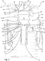
- Fig. 1 shows a liquid dispenser 100 according to the invention, in this case a liquid dispenser for dispensing cosmetic lotions.
- the liquid dispenser 100 has a liquid reservoir 110 in a bottle-like shape, at the upper end of which an outlet nozzle is arranged.
- the liquid reservoir 110 is screwed into a discharge head 10, which in turn has a base 20, on which an actuating handle 40 designed as a pusher is slidably mounted in an actuating direction 2 for the purpose of discharging liquid through a discharge opening 44.
- the discharge head 10 has an in Fig. 1 Pumping device 60, not shown, with the liquid from the liquid storage 110 can be promoted to a discharge opening 44.
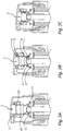
- Fig. 2 shows the discharge head 10 in enlarged and sectional view.
- the discharge head is constructed for the purpose of low-cost design of only a few components, namely in the core only from the base 20 forming component, the actuating handle 40 forming a component and a pumping chamber 66, which simultaneously limits a pumping chamber 64 on the outside and the valve flaps 72, 82nd 92 forms three valves 70, 80, 90, namely an inlet valve 80 between the liquid storage 110 and the pumping chamber 64, an outlet valve 70 between the pumping chamber 64 and an environment and a venting valve 90 between the environment and the liquid storage 110.
- the liquid dispenser 100 may still have a riser 102, a seal 104 in the form of a sealing ring between the discharge head 10 and liquid reservoir 110 and a cap, not shown in the figures.
- the total donor can thus be made up of only 4 to 7 parts, which greatly simplifies manufacturing and assembly.
- the base 20 of the in Fig. 2 illustrated discharge head has a coupling device 24 in the manner of an internal thread, via a provided with ventilation openings 26 end face 25 and an outer sleeve 27, in which the actuating handle 40 is guided limitedly displaceable.
- the end face 25 is pierced by a liquid inlet 22 with an inlet sleeve 23 which has an opening 28 at the end for discharging liquid into the pumping chamber 64 and serves to clamp the pump chamber component 66.
- the inlet valve 80 and its peripheral valve flap 82 are provided, wherein an end-side annular surface at the end of the inlet sleeve 23 forms a valve face 84 of the inlet valve.
- a ring structure is further provided, the inside of which forms a valve face 94 of the ventilation valve 90.
- the actuating handle 40 of in Fig. 2 shown discharge head is guided by means of a jacket 45 slidably on the base 20. At the upper end of the jacket 45, the discharge opening 44 is arranged. An end face of the actuating handle 40 forms the actuating surface 42.
- an annular holding structure 46 for clamping the pump chamber component 66. Within the support structure 46, a further annular web is provided, whose outer side forms a valve surface 74 of the exhaust valve 70.
- valve flaps 72, 82 are at the same pressure on both sides inwardly vorgesplannt to the respective valve surface 74, 84 at.
- a third valve flap 92 of the ventilation valve 90 is biased outwards on the valve surface 94 at the same pressure on both sides. All three valve flaps 72, 82, 92 are configured circumferentially and therefore have a conical-section-shaped or cylindrical shape.
- a circumferential attachment portion 54 is provided, by means of which the pumping chamber component 66 is clamped in the support structure 46, whereby a tight coupling of the pumping chamber to the discharge opening 44 is created.
- a thin tilting ridge 56 extends radially inwardly, wherein in the present embodiment, a notch 56A is provided so that the tilting ridge unfolds the decoupling effect further explained below.
- the valve flap 72 closes counter to the direction of actuation 2, while in the opposite direction the bellows-like pumping chamber wall 62 extends in the direction of the base 20.
- the lower end of the pump chamber component 66 forms a circumferential attachment portion 55 which is clamped onto the inlet sleeve 23.
- the valve flap 82 is formed.
- a tilting and pushing ridge 57,58 adjoins the fastening section 55, which in turn is made comparatively thin by means of a peripheral notch 57A.
- the lower end of the bellows-like pumping chamber wall 62 adjoins it in the direction of the actuating handle 40.
- the valve flap 92 of the ventilation valve 90 connects.
- the design of the pumping chamber component 66 with said elements and in particular the valve flaps 72, 82, 92 serves the purpose of influencing the force with which the ends of the valve flaps 72, 82, 92 due to their connection to other parts of the pumping chamber component 66 against the valve surfaces 74, 84, 94 are pressed.
- the pumping chamber component 66 and in particular its bellows-like pumping chamber wall 62 form an active element 50 for controlling this respective force.
- the tilting and pushing ridge 58 further causes the partial section 53 and the valve flap 92 to be displaced slightly relative to the fastening section 54 in the direction of the arrow 7. This results in a tensile force in the pump chamber 64 facing side of the valve flaps 82 of the inlet valve 80, whereby in this a moment is coupled, which acts in the direction of arrow 8 and also reduces the contact force on the valve surface 84 on this valve flap.
- the state achieved in this case represents an intermediate position of the actuating handle 40.
- the respectively reduced contact force of the valve flaps 72, 82, 92 on the valve surfaces 74, 84, 94 in this state causes each of the valves to reduce the limit overpressure needed to open the valve becomes.
- the limit pressure at the outlet valve 70 is already reduced by about 30%.
- the limit overpressure is reduced by about 20%.
- the limit pressure is reduced by about 50%.
- the deformations are respectively reinforced, so that the contact pressure of the valve flaps 72, 82, 94 on the valve surfaces 74, 84, 94 continues to decrease.
- the limit pressure at the exhaust valve 70 and at the intake valve 80 is reduced to about 50% and about 30% of the original limit overpressure in the unactuated end position, respectively.
- the limit overpressure has dropped to 0 bar, so that the valve flap 92 has detached from the valve surface 94 and the vent valve 90 is thus open.
- the pumping chamber wall 62 causes a restoring force, by which the actuating handle 40 on the state of Fig. 3B back to the state of FIG. 3A is pressed.
- the inlet valve opens immediately, since the restoring force is maximum at this moment and since the limit overpressure for opening the inlet valve is minimal. It therefore begins immediately refilling the pumping chamber 64.
- the previously open vent valve 90 allows unimpeded inflow of compensation air through the vent openings 26 in the liquid storage and remains reliably open during the predominant chairhubweges.
- a very quick return of the actuating handle 40 with complete refilling of the pumping chamber 64 is the result. After re - reaching the unactuated end position of the FIG. 3A The next actuation stroke can follow immediately.
Landscapes
- Reciprocating Pumps (AREA)
- Containers And Packaging Bodies Having A Special Means To Remove Contents (AREA)
Priority Applications (6)
| Application Number | Priority Date | Filing Date | Title |
|---|---|---|---|
| EP17181288.6A EP3427840B1 (fr) | 2017-07-13 | 2017-07-13 | Distributeur de liquide |
| PCT/EP2018/066686 WO2019011622A1 (fr) | 2017-07-13 | 2018-06-21 | Distributeur de liquide |
| CN201880046766.XA CN110831704B (zh) | 2017-07-13 | 2018-06-21 | 液体分配器 |
| BR112019027936-9A BR112019027936B1 (pt) | 2017-07-13 | 2018-06-21 | Cabeça de descarga para um dispensador de líquido e dispensador de líquido |
| US16/625,411 US11179739B2 (en) | 2017-07-13 | 2018-06-21 | Liquid dispenser |
| KR1020207000013A KR102503350B1 (ko) | 2017-07-13 | 2018-06-21 | 액체 분배기 |
Applications Claiming Priority (1)
| Application Number | Priority Date | Filing Date | Title |
|---|---|---|---|
| EP17181288.6A EP3427840B1 (fr) | 2017-07-13 | 2017-07-13 | Distributeur de liquide |
Publications (2)
| Publication Number | Publication Date |
|---|---|
| EP3427840A1 true EP3427840A1 (fr) | 2019-01-16 |
| EP3427840B1 EP3427840B1 (fr) | 2020-12-02 |
Family
ID=59337584
Family Applications (1)
| Application Number | Title | Priority Date | Filing Date |
|---|---|---|---|
| EP17181288.6A Active EP3427840B1 (fr) | 2017-07-13 | 2017-07-13 | Distributeur de liquide |
Country Status (6)
| Country | Link |
|---|---|
| US (1) | US11179739B2 (fr) |
| EP (1) | EP3427840B1 (fr) |
| KR (1) | KR102503350B1 (fr) |
| CN (1) | CN110831704B (fr) |
| BR (1) | BR112019027936B1 (fr) |
| WO (1) | WO2019011622A1 (fr) |
Cited By (2)
| Publication number | Priority date | Publication date | Assignee | Title |
|---|---|---|---|---|
| EP3736049A1 (fr) | 2019-05-06 | 2020-11-11 | Aptar Radolfzell GmbH | Tête distributrice et distributeur de liquide comprenant une tête distributrice |
| EP3919181A1 (fr) * | 2020-06-05 | 2021-12-08 | Ningbo Shunde Medical Technology Co., Ltd. | Distributeur de liquide entièrement en plastique |
Families Citing this family (3)
| Publication number | Priority date | Publication date | Assignee | Title |
|---|---|---|---|---|
| FR3068265B1 (fr) * | 2017-06-28 | 2022-02-25 | Gb Dev | Distributeur de fluide par pression sur une paroi deformable du contenant |
| EP3895809B1 (fr) * | 2020-04-14 | 2024-03-06 | Aptar Radolfzell GmbH | Procédé d'évaluation d'un mouvement de pompage ainsi que distributeur de liquide et unité d'évaluation utilisant ledit procédé |
| IT202200015306A1 (it) * | 2022-07-21 | 2024-01-21 | Aptar Italia S P A | Dispenser per l’erogazione di un fluido |
Citations (11)
| Publication number | Priority date | Publication date | Assignee | Title |
|---|---|---|---|---|
| US4201317A (en) * | 1977-07-28 | 1980-05-06 | Aleff Hans P | Finger actuated pump assembly |
| DE4041136A1 (de) * | 1990-12-21 | 1992-07-02 | Andris Raimund Gmbh & Co Kg | Dosier- und spraypumpe zur abgabe fluessiger, niederviskoser und pastoeser stoffe |
| DE19729516A1 (de) * | 1997-07-10 | 1999-01-21 | Georg Wiegner | Pumpe zum dosierten Austragen von flüssigen, gelartigen oder viskosen Substanzen |
| US6755327B1 (en) * | 2001-08-29 | 2004-06-29 | Richard H. Davey, Inc. | Dispensing pump with deformable pump wall and positive shut-off |
| WO2006031110A1 (fr) | 2004-09-16 | 2006-03-23 | Keltub B.V. | Systeme de soufflet et piece associee |
| DE60304349T2 (de) * | 2002-07-03 | 2006-10-19 | Keltub B.V. | Balgsystem und damit zusammenwirkendes teil, pumpe und verwendungsverfahren dafür |
| US20100116849A1 (en) * | 2007-04-24 | 2010-05-13 | Plastohm Sa | Device for dispensing a liquid to pasty product with a metering pump |
| EP2210674A2 (fr) | 2009-01-23 | 2010-07-28 | Ing. Erich Pfeiffer GmbH | Dispositif de sortie |
| WO2010106256A1 (fr) | 2009-03-18 | 2010-09-23 | Promens Sa | Dispositif de distribution d'un produit liquide a pateux par pompe de dosage, a faible volume mort |
| DE102014200867A1 (de) * | 2014-01-17 | 2015-08-06 | Aptar Radolfzell Gmbh | Spender für Flüssigkeiten |
| EP2763796B1 (fr) | 2011-10-05 | 2015-11-25 | Alfred Von Schuckmann | Distributeur de substances pâteuses |
Family Cites Families (12)
| Publication number | Priority date | Publication date | Assignee | Title |
|---|---|---|---|---|
| ZA885235B (en) * | 1987-08-28 | 1989-04-26 | Andris Raimund | Metering and spray pump |
| DE3837704C2 (de) * | 1988-11-07 | 1994-03-24 | Andris Raimund Gmbh & Co Kg | Pastenspender |
| DE4207800C1 (fr) * | 1992-03-12 | 1993-09-16 | Raimund Andris Gmbh & Co Kg, 7730 Villingen-Schwenningen, De | |
| WO1995000253A1 (fr) * | 1993-06-24 | 1995-01-05 | The Procter & Gamble Company | Chambre de pompe pouvant s'aplatir suivant un schema predetermine |
| US5544789A (en) * | 1995-01-05 | 1996-08-13 | Calmar Inc. | Bellows pump dispenser |
| DE19605153A1 (de) * | 1996-02-13 | 1997-08-14 | Pfeiffer Erich Gmbh & Co Kg | Austragvorrichtung für Medien und Verfahren zur Herstellung einer Austragvorrichtung o. dgl. |
| DE202005019298U1 (de) * | 2005-08-01 | 2006-12-07 | Megaplast Gmbh & Co. Kg | Spender zur portionierten Ausgabe |
| EP2300171B1 (fr) | 2008-05-20 | 2012-09-26 | Francis Poizot | Amelioration d'une pompe pour distributeur a reservoir sans air |
| EP2644279A1 (fr) * | 2009-06-17 | 2013-10-02 | S.C. Johnson & Son, Inc. | Dispositif portable pour distribution de fluides |
| FR2976981B1 (fr) | 2011-06-27 | 2013-07-05 | Promens Sa | Systeme de fermeture d'un dispositif de distribution a basse pression d'un produit liquide a pateux |
| NL2011199C2 (en) | 2013-07-19 | 2015-01-21 | Jan Kelders Beheer B V | Dispenser and method for dispensing fluids from a liquid holder. |
| EP3023752A1 (fr) | 2014-11-18 | 2016-05-25 | Aptar Radolfzell GmbH | Distributeur de liquide et tête distributrice correspondante |
-
2017
- 2017-07-13 EP EP17181288.6A patent/EP3427840B1/fr active Active
-
2018
- 2018-06-21 CN CN201880046766.XA patent/CN110831704B/zh active Active
- 2018-06-21 KR KR1020207000013A patent/KR102503350B1/ko active IP Right Grant
- 2018-06-21 US US16/625,411 patent/US11179739B2/en active Active
- 2018-06-21 BR BR112019027936-9A patent/BR112019027936B1/pt active IP Right Grant
- 2018-06-21 WO PCT/EP2018/066686 patent/WO2019011622A1/fr active Application Filing
Patent Citations (11)
| Publication number | Priority date | Publication date | Assignee | Title |
|---|---|---|---|---|
| US4201317A (en) * | 1977-07-28 | 1980-05-06 | Aleff Hans P | Finger actuated pump assembly |
| DE4041136A1 (de) * | 1990-12-21 | 1992-07-02 | Andris Raimund Gmbh & Co Kg | Dosier- und spraypumpe zur abgabe fluessiger, niederviskoser und pastoeser stoffe |
| DE19729516A1 (de) * | 1997-07-10 | 1999-01-21 | Georg Wiegner | Pumpe zum dosierten Austragen von flüssigen, gelartigen oder viskosen Substanzen |
| US6755327B1 (en) * | 2001-08-29 | 2004-06-29 | Richard H. Davey, Inc. | Dispensing pump with deformable pump wall and positive shut-off |
| DE60304349T2 (de) * | 2002-07-03 | 2006-10-19 | Keltub B.V. | Balgsystem und damit zusammenwirkendes teil, pumpe und verwendungsverfahren dafür |
| WO2006031110A1 (fr) | 2004-09-16 | 2006-03-23 | Keltub B.V. | Systeme de soufflet et piece associee |
| US20100116849A1 (en) * | 2007-04-24 | 2010-05-13 | Plastohm Sa | Device for dispensing a liquid to pasty product with a metering pump |
| EP2210674A2 (fr) | 2009-01-23 | 2010-07-28 | Ing. Erich Pfeiffer GmbH | Dispositif de sortie |
| WO2010106256A1 (fr) | 2009-03-18 | 2010-09-23 | Promens Sa | Dispositif de distribution d'un produit liquide a pateux par pompe de dosage, a faible volume mort |
| EP2763796B1 (fr) | 2011-10-05 | 2015-11-25 | Alfred Von Schuckmann | Distributeur de substances pâteuses |
| DE102014200867A1 (de) * | 2014-01-17 | 2015-08-06 | Aptar Radolfzell Gmbh | Spender für Flüssigkeiten |
Cited By (5)
| Publication number | Priority date | Publication date | Assignee | Title |
|---|---|---|---|---|
| EP3736049A1 (fr) | 2019-05-06 | 2020-11-11 | Aptar Radolfzell GmbH | Tête distributrice et distributeur de liquide comprenant une tête distributrice |
| WO2020225223A1 (fr) | 2019-05-06 | 2020-11-12 | Aptar Radolfzell Gmbh | Tête de décharge et distributeur de liquide pourvu d'une tête de décharge |
| EP4151317A1 (fr) | 2019-05-06 | 2023-03-22 | Aptar Radolfzell GmbH | Tête de distribution et distributeur de liquide doté d'une tête de distribution |
| US11938495B2 (en) | 2019-05-06 | 2024-03-26 | Aptar Radolfzell Gmbh | Discharge head and liquid dispenser comprising a discharge head |
| EP3919181A1 (fr) * | 2020-06-05 | 2021-12-08 | Ningbo Shunde Medical Technology Co., Ltd. | Distributeur de liquide entièrement en plastique |
Also Published As
| Publication number | Publication date |
|---|---|
| US20210121904A1 (en) | 2021-04-29 |
| BR112019027936A2 (pt) | 2020-07-14 |
| KR20200032085A (ko) | 2020-03-25 |
| BR112019027936B1 (pt) | 2022-12-20 |
| EP3427840B1 (fr) | 2020-12-02 |
| CN110831704A (zh) | 2020-02-21 |
| KR102503350B1 (ko) | 2023-02-23 |
| WO2019011622A1 (fr) | 2019-01-17 |
| US11179739B2 (en) | 2021-11-23 |
| CN110831704B (zh) | 2022-02-18 |
Similar Documents
| Publication | Publication Date | Title |
|---|---|---|
| EP3427840B1 (fr) | Distributeur de liquide | |
| EP3094416B1 (fr) | Distributeur pour liquides | |
| DE60035828T2 (de) | Austragsventileinrichtung für eine hebelbetätigte Sprühvorrichtung | |
| EP0882516B1 (fr) | Distributer de fluide | |
| EP2236213B1 (fr) | Dispositif de sortie | |
| DE69821495T2 (de) | Handpumpe mit durch Plastikfedern beaufschlagtem Freikolben | |
| DE4102506A1 (de) | Austragvorrichtung fuer medien | |
| DE2227407B2 (fr) | ||
| EP1834704A2 (fr) | Distributeur de produit fluide | |
| WO2003026805A1 (fr) | Dispositif de dosage pourvu d'un reservoir de substances et dispositif de pompage correspondant | |
| EP3323753B1 (fr) | Tête de distribution et distributeur de liquide comprenant une telle tête de distribution | |
| DE2001921A1 (de) | Hin- und herbewegte Fluessigkeitsabgabepumpe | |
| EP3978389B1 (fr) | Distributeur de liquide, en particulier distributeur de gouttes | |
| DE102011082420A1 (de) | Flüssigkeitsspender | |
| EP3730220B1 (fr) | Distributeur destiné à la sortie des liquides pharmaceutiques | |
| EP3536634A1 (fr) | Distributeur destiné à la distribution de liquides et procédé de fonctionnement correspondant | |
| DE69612587T2 (de) | Pumpenvorrichtung zum Entnehmen einer Flüssigkeit aus einem Behälter und zu deren Zerstäubung | |
| DE102005009295A1 (de) | Dosiervorrichtung für Medien | |
| DE69624642T2 (de) | Pumpenmechanismus | |
| EP2654967A2 (fr) | Dispositif distributeur pour liquide | |
| EP1514608B1 (fr) | Dispositif de dosage comprenant un actionneur élastique | |
| EP3736049B1 (fr) | Tête distributrice et distributeur de liquide comprenant une tête distributrice | |
| EP3730219B1 (fr) | Distributeur destiné à la sortie des liquides pharmaceutiques | |
| EP2246122B1 (fr) | Dispositif de sortie pour milieux liquides ou pâteux | |
| EP3694654A1 (fr) | Distributeur de matières liquides ou pâteuses |
Legal Events
| Date | Code | Title | Description |
|---|---|---|---|
| PUAI | Public reference made under article 153(3) epc to a published international application that has entered the european phase |
Free format text: ORIGINAL CODE: 0009012 |
|
| STAA | Information on the status of an ep patent application or granted ep patent |
Free format text: STATUS: THE APPLICATION HAS BEEN PUBLISHED |
|
| AK | Designated contracting states |
Kind code of ref document: A1 Designated state(s): AL AT BE BG CH CY CZ DE DK EE ES FI FR GB GR HR HU IE IS IT LI LT LU LV MC MK MT NL NO PL PT RO RS SE SI SK SM TR |
|
| AX | Request for extension of the european patent |
Extension state: BA ME |
|
| STAA | Information on the status of an ep patent application or granted ep patent |
Free format text: STATUS: REQUEST FOR EXAMINATION WAS MADE |
|
| 17P | Request for examination filed |
Effective date: 20190711 |
|
| RBV | Designated contracting states (corrected) |
Designated state(s): AL AT BE BG CH CY CZ DE DK EE ES FI FR GB GR HR HU IE IS IT LI LT LU LV MC MK MT NL NO PL PT RO RS SE SI SK SM TR |
|
| GRAP | Despatch of communication of intention to grant a patent |
Free format text: ORIGINAL CODE: EPIDOSNIGR1 |
|
| STAA | Information on the status of an ep patent application or granted ep patent |
Free format text: STATUS: GRANT OF PATENT IS INTENDED |
|
| INTG | Intention to grant announced |
Effective date: 20200916 |
|
| GRAS | Grant fee paid |
Free format text: ORIGINAL CODE: EPIDOSNIGR3 |
|
| GRAA | (expected) grant |
Free format text: ORIGINAL CODE: 0009210 |
|
| STAA | Information on the status of an ep patent application or granted ep patent |
Free format text: STATUS: THE PATENT HAS BEEN GRANTED |
|
| AK | Designated contracting states |
Kind code of ref document: B1 Designated state(s): AL AT BE BG CH CY CZ DE DK EE ES FI FR GB GR HR HU IE IS IT LI LT LU LV MC MK MT NL NO PL PT RO RS SE SI SK SM TR |
|
| REG | Reference to a national code |
Ref country code: GB Ref legal event code: FG4D Free format text: NOT ENGLISH |
|
| REG | Reference to a national code |
Ref country code: AT Ref legal event code: REF Ref document number: 1340313 Country of ref document: AT Kind code of ref document: T Effective date: 20201215 Ref country code: CH Ref legal event code: EP |
|
| REG | Reference to a national code |
Ref country code: DE Ref legal event code: R096 Ref document number: 502017008433 Country of ref document: DE |
|
| REG | Reference to a national code |
Ref country code: IE Ref legal event code: FG4D Free format text: LANGUAGE OF EP DOCUMENT: GERMAN |
|
| PG25 | Lapsed in a contracting state [announced via postgrant information from national office to epo] |
Ref country code: NO Free format text: LAPSE BECAUSE OF FAILURE TO SUBMIT A TRANSLATION OF THE DESCRIPTION OR TO PAY THE FEE WITHIN THE PRESCRIBED TIME-LIMIT Effective date: 20210302 Ref country code: RS Free format text: LAPSE BECAUSE OF FAILURE TO SUBMIT A TRANSLATION OF THE DESCRIPTION OR TO PAY THE FEE WITHIN THE PRESCRIBED TIME-LIMIT Effective date: 20201202 Ref country code: GR Free format text: LAPSE BECAUSE OF FAILURE TO SUBMIT A TRANSLATION OF THE DESCRIPTION OR TO PAY THE FEE WITHIN THE PRESCRIBED TIME-LIMIT Effective date: 20210303 Ref country code: FI Free format text: LAPSE BECAUSE OF FAILURE TO SUBMIT A TRANSLATION OF THE DESCRIPTION OR TO PAY THE FEE WITHIN THE PRESCRIBED TIME-LIMIT Effective date: 20201202 |
|
| REG | Reference to a national code |
Ref country code: NL Ref legal event code: MP Effective date: 20201202 |
|
| PG25 | Lapsed in a contracting state [announced via postgrant information from national office to epo] |
Ref country code: BG Free format text: LAPSE BECAUSE OF FAILURE TO SUBMIT A TRANSLATION OF THE DESCRIPTION OR TO PAY THE FEE WITHIN THE PRESCRIBED TIME-LIMIT Effective date: 20210302 Ref country code: LV Free format text: LAPSE BECAUSE OF FAILURE TO SUBMIT A TRANSLATION OF THE DESCRIPTION OR TO PAY THE FEE WITHIN THE PRESCRIBED TIME-LIMIT Effective date: 20201202 Ref country code: PL Free format text: LAPSE BECAUSE OF FAILURE TO SUBMIT A TRANSLATION OF THE DESCRIPTION OR TO PAY THE FEE WITHIN THE PRESCRIBED TIME-LIMIT Effective date: 20201202 Ref country code: SE Free format text: LAPSE BECAUSE OF FAILURE TO SUBMIT A TRANSLATION OF THE DESCRIPTION OR TO PAY THE FEE WITHIN THE PRESCRIBED TIME-LIMIT Effective date: 20201202 |
|
| PG25 | Lapsed in a contracting state [announced via postgrant information from national office to epo] |
Ref country code: NL Free format text: LAPSE BECAUSE OF FAILURE TO SUBMIT A TRANSLATION OF THE DESCRIPTION OR TO PAY THE FEE WITHIN THE PRESCRIBED TIME-LIMIT Effective date: 20201202 Ref country code: HR Free format text: LAPSE BECAUSE OF FAILURE TO SUBMIT A TRANSLATION OF THE DESCRIPTION OR TO PAY THE FEE WITHIN THE PRESCRIBED TIME-LIMIT Effective date: 20201202 |
|
| REG | Reference to a national code |
Ref country code: LT Ref legal event code: MG9D |
|
| PG25 | Lapsed in a contracting state [announced via postgrant information from national office to epo] |
Ref country code: SM Free format text: LAPSE BECAUSE OF FAILURE TO SUBMIT A TRANSLATION OF THE DESCRIPTION OR TO PAY THE FEE WITHIN THE PRESCRIBED TIME-LIMIT Effective date: 20201202 Ref country code: LT Free format text: LAPSE BECAUSE OF FAILURE TO SUBMIT A TRANSLATION OF THE DESCRIPTION OR TO PAY THE FEE WITHIN THE PRESCRIBED TIME-LIMIT Effective date: 20201202 Ref country code: CZ Free format text: LAPSE BECAUSE OF FAILURE TO SUBMIT A TRANSLATION OF THE DESCRIPTION OR TO PAY THE FEE WITHIN THE PRESCRIBED TIME-LIMIT Effective date: 20201202 Ref country code: EE Free format text: LAPSE BECAUSE OF FAILURE TO SUBMIT A TRANSLATION OF THE DESCRIPTION OR TO PAY THE FEE WITHIN THE PRESCRIBED TIME-LIMIT Effective date: 20201202 Ref country code: PT Free format text: LAPSE BECAUSE OF FAILURE TO SUBMIT A TRANSLATION OF THE DESCRIPTION OR TO PAY THE FEE WITHIN THE PRESCRIBED TIME-LIMIT Effective date: 20210405 Ref country code: RO Free format text: LAPSE BECAUSE OF FAILURE TO SUBMIT A TRANSLATION OF THE DESCRIPTION OR TO PAY THE FEE WITHIN THE PRESCRIBED TIME-LIMIT Effective date: 20201202 Ref country code: SK Free format text: LAPSE BECAUSE OF FAILURE TO SUBMIT A TRANSLATION OF THE DESCRIPTION OR TO PAY THE FEE WITHIN THE PRESCRIBED TIME-LIMIT Effective date: 20201202 |
|
| REG | Reference to a national code |
Ref country code: DE Ref legal event code: R097 Ref document number: 502017008433 Country of ref document: DE |
|
| PG25 | Lapsed in a contracting state [announced via postgrant information from national office to epo] |
Ref country code: IS Free format text: LAPSE BECAUSE OF FAILURE TO SUBMIT A TRANSLATION OF THE DESCRIPTION OR TO PAY THE FEE WITHIN THE PRESCRIBED TIME-LIMIT Effective date: 20210402 |
|
| PLBE | No opposition filed within time limit |
Free format text: ORIGINAL CODE: 0009261 |
|
| STAA | Information on the status of an ep patent application or granted ep patent |
Free format text: STATUS: NO OPPOSITION FILED WITHIN TIME LIMIT |
|
| PG25 | Lapsed in a contracting state [announced via postgrant information from national office to epo] |
Ref country code: IT Free format text: LAPSE BECAUSE OF FAILURE TO SUBMIT A TRANSLATION OF THE DESCRIPTION OR TO PAY THE FEE WITHIN THE PRESCRIBED TIME-LIMIT Effective date: 20201202 Ref country code: AL Free format text: LAPSE BECAUSE OF FAILURE TO SUBMIT A TRANSLATION OF THE DESCRIPTION OR TO PAY THE FEE WITHIN THE PRESCRIBED TIME-LIMIT Effective date: 20201202 |
|
| 26N | No opposition filed |
Effective date: 20210903 |
|
| PG25 | Lapsed in a contracting state [announced via postgrant information from national office to epo] |
Ref country code: DK Free format text: LAPSE BECAUSE OF FAILURE TO SUBMIT A TRANSLATION OF THE DESCRIPTION OR TO PAY THE FEE WITHIN THE PRESCRIBED TIME-LIMIT Effective date: 20201202 Ref country code: SI Free format text: LAPSE BECAUSE OF FAILURE TO SUBMIT A TRANSLATION OF THE DESCRIPTION OR TO PAY THE FEE WITHIN THE PRESCRIBED TIME-LIMIT Effective date: 20201202 |
|
| PG25 | Lapsed in a contracting state [announced via postgrant information from national office to epo] |
Ref country code: ES Free format text: LAPSE BECAUSE OF FAILURE TO SUBMIT A TRANSLATION OF THE DESCRIPTION OR TO PAY THE FEE WITHIN THE PRESCRIBED TIME-LIMIT Effective date: 20201202 |
|
| REG | Reference to a national code |
Ref country code: CH Ref legal event code: PL |
|
| GBPC | Gb: european patent ceased through non-payment of renewal fee |
Effective date: 20210713 |
|
| PG25 | Lapsed in a contracting state [announced via postgrant information from national office to epo] |
Ref country code: MC Free format text: LAPSE BECAUSE OF FAILURE TO SUBMIT A TRANSLATION OF THE DESCRIPTION OR TO PAY THE FEE WITHIN THE PRESCRIBED TIME-LIMIT Effective date: 20201202 |
|
| REG | Reference to a national code |
Ref country code: BE Ref legal event code: MM Effective date: 20210731 |
|
| REG | Reference to a national code |
Ref country code: DE Ref legal event code: R082 Ref document number: 502017008433 Country of ref document: DE Representative=s name: WITTE, WELLER & PARTNER PATENTANWAELTE MBB, DE |
|
| PG25 | Lapsed in a contracting state [announced via postgrant information from national office to epo] |
Ref country code: LI Free format text: LAPSE BECAUSE OF NON-PAYMENT OF DUE FEES Effective date: 20210731 Ref country code: GB Free format text: LAPSE BECAUSE OF NON-PAYMENT OF DUE FEES Effective date: 20210713 Ref country code: CH Free format text: LAPSE BECAUSE OF NON-PAYMENT OF DUE FEES Effective date: 20210731 |
|
| PG25 | Lapsed in a contracting state [announced via postgrant information from national office to epo] |
Ref country code: IS Free format text: LAPSE BECAUSE OF FAILURE TO SUBMIT A TRANSLATION OF THE DESCRIPTION OR TO PAY THE FEE WITHIN THE PRESCRIBED TIME-LIMIT Effective date: 20210402 Ref country code: LU Free format text: LAPSE BECAUSE OF NON-PAYMENT OF DUE FEES Effective date: 20210713 |
|
| PG25 | Lapsed in a contracting state [announced via postgrant information from national office to epo] |
Ref country code: IE Free format text: LAPSE BECAUSE OF NON-PAYMENT OF DUE FEES Effective date: 20210713 Ref country code: BE Free format text: LAPSE BECAUSE OF NON-PAYMENT OF DUE FEES Effective date: 20210731 |
|
| P01 | Opt-out of the competence of the unified patent court (upc) registered |
Effective date: 20230502 |
|
| PG25 | Lapsed in a contracting state [announced via postgrant information from national office to epo] |
Ref country code: CY Free format text: LAPSE BECAUSE OF FAILURE TO SUBMIT A TRANSLATION OF THE DESCRIPTION OR TO PAY THE FEE WITHIN THE PRESCRIBED TIME-LIMIT Effective date: 20201202 |
|
| PG25 | Lapsed in a contracting state [announced via postgrant information from national office to epo] |
Ref country code: HU Free format text: LAPSE BECAUSE OF FAILURE TO SUBMIT A TRANSLATION OF THE DESCRIPTION OR TO PAY THE FEE WITHIN THE PRESCRIBED TIME-LIMIT; INVALID AB INITIO Effective date: 20170713 |
|
| REG | Reference to a national code |
Ref country code: AT Ref legal event code: MM01 Ref document number: 1340313 Country of ref document: AT Kind code of ref document: T Effective date: 20220713 |
|
| PG25 | Lapsed in a contracting state [announced via postgrant information from national office to epo] |
Ref country code: AT Free format text: LAPSE BECAUSE OF NON-PAYMENT OF DUE FEES Effective date: 20220713 |
|
| PGFP | Annual fee paid to national office [announced via postgrant information from national office to epo] |
Ref country code: FR Payment date: 20230724 Year of fee payment: 7 Ref country code: DE Payment date: 20230720 Year of fee payment: 7 |
|
| PG25 | Lapsed in a contracting state [announced via postgrant information from national office to epo] |
Ref country code: MK Free format text: LAPSE BECAUSE OF FAILURE TO SUBMIT A TRANSLATION OF THE DESCRIPTION OR TO PAY THE FEE WITHIN THE PRESCRIBED TIME-LIMIT Effective date: 20201202 |