EP3427427B1 - Verfahren und vorrichtung zur signalspreizung und -multiplexierung - Google Patents
Verfahren und vorrichtung zur signalspreizung und -multiplexierung Download PDFInfo
- Publication number
- EP3427427B1 EP3427427B1 EP17781875.4A EP17781875A EP3427427B1 EP 3427427 B1 EP3427427 B1 EP 3427427B1 EP 17781875 A EP17781875 A EP 17781875A EP 3427427 B1 EP3427427 B1 EP 3427427B1
- Authority
- EP
- European Patent Office
- Prior art keywords
- streams
- binary
- stream
- bit
- symbol
- Prior art date
- Legal status (The legal status is an assumption and is not a legal conclusion. Google has not performed a legal analysis and makes no representation as to the accuracy of the status listed.)
- Active
Links
Images


Classifications
-
- H—ELECTRICITY
- H04—ELECTRIC COMMUNICATION TECHNIQUE
- H04B—TRANSMISSION
- H04B1/00—Details of transmission systems, not covered by a single one of groups H04B3/00 - H04B13/00; Details of transmission systems not characterised by the medium used for transmission
- H04B1/69—Spread spectrum techniques
- H04B1/707—Spread spectrum techniques using direct sequence modulation
- H04B1/7097—Interference-related aspects
- H04B1/7103—Interference-related aspects the interference being multiple access interference
- H04B1/7105—Joint detection techniques, e.g. linear detectors
- H04B1/71057—Joint detection techniques, e.g. linear detectors using maximum-likelihood sequence estimation [MLSE]
-
- H—ELECTRICITY
- H04—ELECTRIC COMMUNICATION TECHNIQUE
- H04B—TRANSMISSION
- H04B1/00—Details of transmission systems, not covered by a single one of groups H04B3/00 - H04B13/00; Details of transmission systems not characterised by the medium used for transmission
- H04B1/69—Spread spectrum techniques
-
- H—ELECTRICITY
- H04—ELECTRIC COMMUNICATION TECHNIQUE
- H04L—TRANSMISSION OF DIGITAL INFORMATION, e.g. TELEGRAPHIC COMMUNICATION
- H04L1/00—Arrangements for detecting or preventing errors in the information received
-
- H—ELECTRICITY
- H04—ELECTRIC COMMUNICATION TECHNIQUE
- H04L—TRANSMISSION OF DIGITAL INFORMATION, e.g. TELEGRAPHIC COMMUNICATION
- H04L1/00—Arrangements for detecting or preventing errors in the information received
- H04L1/004—Arrangements for detecting or preventing errors in the information received by using forward error control
- H04L1/0041—Arrangements at the transmitter end
- H04L1/0042—Encoding specially adapted to other signal generation operation, e.g. in order to reduce transmit distortions, jitter, or to improve signal shape
-
- H—ELECTRICITY
- H04—ELECTRIC COMMUNICATION TECHNIQUE
- H04L—TRANSMISSION OF DIGITAL INFORMATION, e.g. TELEGRAPHIC COMMUNICATION
- H04L1/00—Arrangements for detecting or preventing errors in the information received
- H04L1/004—Arrangements for detecting or preventing errors in the information received by using forward error control
- H04L1/0041—Arrangements at the transmitter end
- H04L1/0043—Realisations of complexity reduction techniques, e.g. use of look-up tables
-
- H—ELECTRICITY
- H04—ELECTRIC COMMUNICATION TECHNIQUE
- H04L—TRANSMISSION OF DIGITAL INFORMATION, e.g. TELEGRAPHIC COMMUNICATION
- H04L1/00—Arrangements for detecting or preventing errors in the information received
- H04L1/004—Arrangements for detecting or preventing errors in the information received by using forward error control
- H04L1/0045—Arrangements at the receiver end
- H04L1/0054—Maximum-likelihood or sequential decoding, e.g. Viterbi, Fano, ZJ algorithms
-
- H—ELECTRICITY
- H04—ELECTRIC COMMUNICATION TECHNIQUE
- H04L—TRANSMISSION OF DIGITAL INFORMATION, e.g. TELEGRAPHIC COMMUNICATION
- H04L1/00—Arrangements for detecting or preventing errors in the information received
- H04L1/004—Arrangements for detecting or preventing errors in the information received by using forward error control
- H04L1/0056—Systems characterized by the type of code used
-
- H—ELECTRICITY
- H04—ELECTRIC COMMUNICATION TECHNIQUE
- H04L—TRANSMISSION OF DIGITAL INFORMATION, e.g. TELEGRAPHIC COMMUNICATION
- H04L27/00—Modulated-carrier systems
- H04L27/32—Carrier systems characterised by combinations of two or more of the types covered by groups H04L27/02, H04L27/10, H04L27/18 or H04L27/26
- H04L27/34—Amplitude- and phase-modulated carrier systems, e.g. quadrature-amplitude modulated carrier systems
- H04L27/3405—Modifications of the signal space to increase the efficiency of transmission, e.g. reduction of the bit error rate, bandwidth, or average power
-
- H—ELECTRICITY
- H04—ELECTRIC COMMUNICATION TECHNIQUE
- H04B—TRANSMISSION
- H04B2201/00—Indexing scheme relating to details of transmission systems not covered by a single group of H04B3/00 - H04B13/00
- H04B2201/69—Orthogonal indexing scheme relating to spread spectrum techniques in general
- H04B2201/707—Orthogonal indexing scheme relating to spread spectrum techniques in general relating to direct sequence modulation
- H04B2201/70716—Quadrature
-
- H—ELECTRICITY
- H04—ELECTRIC COMMUNICATION TECHNIQUE
- H04B—TRANSMISSION
- H04B2201/00—Indexing scheme relating to details of transmission systems not covered by a single group of H04B3/00 - H04B13/00
- H04B2201/69—Orthogonal indexing scheme relating to spread spectrum techniques in general
- H04B2201/707—Orthogonal indexing scheme relating to spread spectrum techniques in general relating to direct sequence modulation
- H04B2201/7097—Direct sequence modulation interference
Definitions
- This application relates to communications, and in particular to spreading a signal and multiplexing a plurality of signals that are to be transmitted.
- FEC Forward Error Correction
- Spreading of a signal over multiple time/frequency resources is performed for the purpose of achieving higher diversity, reliability and robustness to interference and channel variations.
- CDMA Code division multiple access
- Conventional CDMA encoding is a two-step process in which a binary code is mapped to a quadrature amplitude modulation (QAM) symbol before a spreading sequence is applied.
- QAM quadrature amplitude modulation
- CDMA can be considered a form of repetition of QAM symbols by using different amplitude and phases in accordance with the spreading sequence.
- SCMA sparse code multiple access
- EP 1 313 249 A2 concerns an apparatus and method in a receiver for assigning reliability weight factors (RWFs) to soft metrics output from demodulators in a mobile communication system using different modulation schemes.
- RWFs reliability weight factors
- Codeword level scrambling for MIMO transmission is described in WO 2008/058109 A2 .
- EP 2 043 317 A2 suggests encoding an input signal using a forward error correcting code to produce a codeword corresponding to the input signal.
- An embodiment of the invention includes, at a transmitter, generating the signal that includes the data to be transmitted to a plurality of UEs by first using a binary FEC to generate a plurality of coded bit streams for each UE, and then multiplexing the coded bit streams of different UEs to generate a binary stream which is then mapped to a plurality of binary streams using a bit mapping component.
- the method further includes mapping each binary stream to a QAM symbol or another complex-valued modulation symbol using a stream-specific modulator, generating a plurality of QAM symbols or other complex-valued modulation symbols, and mapping the complex-valued modulation symbols to a plurality of complex-valued symbols using non-binary FEC encoding.
- a first comparative method at a receiver includes attempting to decode the data of at least one of a plurality of UEs.
- the comparative method further includes joint maximum likelihood (ML) detection of the data of at least one of the plurality of UEs, calculating the log-likelihood ratios (LLRs) for the coded bits of at least one of the plurality of UEs, and decoding the data of at least one of the plurality of UEs using FEC decoding, e.g. in a Turbo decoder.
- ML joint maximum likelihood
- LLRs log-likelihood ratios
- a comparative method at a receiver involves using a message passing algorithm (MPA) to calculate the LLRs for the coded bits of at least one of a plurality of UEs, and decoding the data of at least one of the plurality of UEs using FEC decoding, e.g. in a Turbo decoder.
- MPA message passing algorithm
- an output of the modulated symbol level sequence generator 24 could be provided to a symbol sequence precoder that performs symbol precoding.
- Such precoding could be intended to reduce the peak to average power ratio (PAPR) of a transmitted signal, which may improve coverage of the transmitted signal.
- PAPR peak to average power ratio
- DFT discrete Fourier transform
- a symbol sequence, which may have been precoded, is provided to the symbol to resource element (RE) mapper 26.
- the modulation symbols are mapped to resource elements for transmission, with or without additional symbol-level interleaving/scrambling.
- a symbol-level interleaver/scrambler could be user-specific, such that each user has a specific symbol-level interleaver/scrambler sequence or scheme, or cell-specific, with a specific symbol-level interleaver/scrambler sequence or scheme being applied for the receiver in each cell or coverage area of a network.
- a waveform modulator could be implemented to generate, after the symbols have been mapped the REs, the actual signal to be transmitted over the air.
- information bits are first encoded using a FEC encoder, and bit-level interleaving/scrambling is applied to coded bits. These are bit-level operations.
- UE-specific, or more generally user-specific, symbol-level operations including modulated symbol sequence generation and symbol-to RE mapping are applied.
- Such a framework may assist a receiver in decoding signals of multiplexed receivers more efficiently.
- Fig. 1 is intended solely as an illustrative example of a multiple access scenario in which disclosed embodiments could be applied. Embodiments disclosed herein could be used, for example, to implement modulated symbol sequence generation at 24 in Fig. 1 . As will be apparent from the other drawings and the following description, however, embodiments could be related to other parts of the NoMA framework illustrated in Fig. 1 .
- Electronic devices that might be suitable for implementing any or all of these components include, among others, microprocessors, microcontrollers, Programmable Logic Devices (PLDs), Field Programmable Gate Arrays (FPGAs), Application Specific Integrated Circuits (ASICs), and/or other types of "intelligent" integrated circuits.
- PLDs Programmable Logic Devices
- FPGAs Field Programmable Gate Arrays
- ASICs Application Specific Integrated Circuits
- the bit mapper 130 could interleave, scramble, or otherwise change the order of the coded bits 120 before they are mapped to the binary sequences 140a-c.
- a separate bit level interleaver / scrambler as shown at 22 in Fig. 1 could be provided and coupled between the binary FEC encoder 110 and the bit mapper 130.
- a bit mapper 130 performs any bit-level interleaving, and a separate bit-level scrambler is coupled between the FEC encoder 110 and the bit mapper.
- the binary sequences 140a-c are mapped to complex-value symbols 160a, 160b and 160c using stream-specific modulators 150a, 150b and 150c.
- the modulators 150a-c could be QPSK modulators, for example. Or, the modulators 150a-c are QAM modulators with Gray labeling or different labeling. Different modulators 150a-c could potentially be used for different streams.
- the set of complex-value symbols 160a, 160b and 160c are fed into the non-binary FEC encoder 170 to generate the output symbols 180 to be transmitted.
- the non-binary FEC encoder 170 could apply a spreading matrix in which the output of each modulator 150a-c is multiplied by a spreading sequence.
- Symbol-level scrambling and/or interleaving could also or instead be implemented by the non-binary FEC encoder 170, by applying a scrambling sequence and/or interleaving matrix to the symbols 160a-c.
- the generated output symbols 180 could be provided as inputs for symbol to RE mapping at 26
- FIG. 2B is a block diagram of an apparatus implementing a signal spreading technique according to another aspect of the disclosure.
- the apparatus in Fig. 2B like the apparatus in Fig. 2A , includes a binary FEC encoder 210, a bit mapper 230 coupled to the binary FEC encoder, and modulators 250a, 250b, 250c coupled to the bit mapper.
- the example implementations of components in Fig. 2A provided above also apply to the corresponding components in Fig. 2B . Operation of components as described above with reference to Fig. 2A also apply to the corresponding components in Fig. 2B .
- the sequence 200 is shown to represent input binary bits that are to be transmitted to a receiver, such as a UE, for uplink communications, and/or for uplink communications from UEs to a base station or a network node. Therefore, a UE is referenced herein as an illustrative example of a receiver. A base station, network node, or other network equipment could also or instead be an intended receiver of transmitted signals.
- Input bits 200 are fed into the binary FEC encoder 210 to generate the sequence of coded bits 220. Then, the sequence of coded bits 220 is fed into the bit mapper 230, which outputs a plurality of output streams 240a, 240b, 240c. Each output binary stream 240a-c is mapped to a stream-specific modulator 250a-c, examples of which are described above with reference to Fig. 2A , generating complex-valued symbols of 260a, 260b, 260c per stream.
- the complex-valued symbols could be encoded by a non-binary FEC encoder as shown at 170 in Fig. 2A , and/or mapped to REs as shown at 26 in Fig. 1 .
- the coded bit stream 220 includes coded bits b0b1b2, bit mapper 230 generates two streams 240a-b of size 2, including a first stream with bits b0b1 and a second stream including bits b1b2, and the modulators 250a-b are QPSK modulators.
- b1 is present in both streams.
- FIG. 3 is a block diagram of an apparatus implementing a signal spreading technique according to another aspect of the disclosure.
- the apparatus in Fig. 3 like the apparatus in Fig. 2A , includes a binary FEC encoder 310, a bit mapper 330 coupled to the binary FEC encoder, and modulators 350a, 350b, 350c coupled to the bit mapper.
- the example implementations of components in Fig. 2A provided above also apply to the corresponding components in Fig. 3 . Operation of components as described above with reference to Fig. 2A also apply to the corresponding components in Fig. 3 .
- the sequence 300 is shown to represent input binary bits to be transmitted to a receiver, such as a UE.
- Input bits 300 are fed into the FEC encoder 310 to generate the sequence of coded bits 320.
- the sequence of coded bits 320 is divided into a plurality of binary sequences 340a, 340b and 340c using a serial to parallel (S/P) converter 330.
- Bit-level interleaving and/or scrambling as shown at 22 in Fig. 1 , could be implemented in an interleaver/scrambler that is coupled between the FEC encoder 310 and the S/P converter 330, or as a feature of the S/P converter 330 itself.
- the binary sequences 340a-c are mapped to complex-value symbols 360a, 360b and 360c using stream-specific modulators 350a, 350b and 350c, examples of which are described above with reference to Fig. 2A .
- the sets of complex-value symbols 360a, 360b and 360c are fed into the symbol-level FEC encoder 370, examples of which are also described above, to generate the output symbols 380 to be transmitted.
- the symbols 380 could be mapped to REs as shown at 26 in Fig. 1 .
- Figs. 2B and 3 represent example implementations of the overall framework of Fig. 2A .
- Signal spreading could be provided by bit mapping at 230 such that the bit streams 240a-c have some common bits and some different bits, by the non-binary FEC encoder 370, or both.
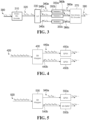
- Figs. 4 and 5 are block diagrams of an apparatus implementing bit mapping and modulation techniques.
- the example implementations and operation of components in Fig. 2A provided above also apply to the corresponding components in Figs. 4 and 5 .
- Figs. 4 and 5 illustrate only a bit mapper and modulators coupled to the bit mapper, other components such as a binary FEC encoder, a bit-level interleaver/scrambler, a non-binary FEC encoder, and/or a symbol to RE mapper, for example.
- the bit mapper 430 maps input bits 420 to bit streams 440a-b such that bits b11 and b12 are common to both bit streams, and bits b01, b02, b21, and b22 are disjoint between the bit streams.
- the QPSK modulators 450a-b are stream-specific modulators in Fig. 4 .
- the bit mapper 430 provides signal spreading, and therefore there may or may not be a non-binary FEC encoder coupled to the QPSK modulators 450a-b.
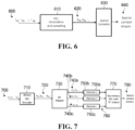
- FIG. 6 is a block diagram of an apparatus implementing a sparse signal spreading technique according to another aspect of the disclosure, an example of sparse spreading will be described.
- the apparatus shown in Fig. 6 includes a FEC modulation and spreading module 610 and a sparse spreader 630.
- the example implementations in Fig. 2A provided above also apply to the components in Fig. 6 .
- Other components such as a bit-level interleaver/scrambler, a non-binary FEC encoder, and/or a symbol to RE mapper.
- Fig. 6 relates to an example in which the generated output symbols 620, generated from input bits 600, are fed into the sparse spreader 630.
- Binary FEC encoding, modulation, and spreading are performed by module 610.
- the sparse spreader 630 maps the output symbols 620 to corresponding non-zero entries of a sparse spreading vector and generates the sparse output symbols 640.
- Sparse symbol to RE mapping could also or instead be implemented in Fig. 6 .
- a sparse symbol to RE mapper instead of the sparse spreader 630, could be coupled to the module 610 to implement sparse symbol to RE mapping.
- the sequences of complex-valued symbols at 760 are fed into non-binary FEC encoder 770 with possible "0" output to generate the sparse output symbols 780.
- the input bits 700, binary FEC encoder 710, coded bit stream 720, bit mapper 730, bit streams 740a-c, and modulators 750a-c are also shown.
- the example implementations and operation of components in Fig. 2A provided above also apply to the corresponding components in Fig. 7 .
- Fig. 8 is a block diagram of a signal spreading and multi-user signal multiplexing apparatus according to another aspect of the disclosure.
- the example implementations of components in Fig. 2A provided above also apply to the components of at least the transmit point 800 in Fig. 8 .
- Such implementations could also be applied to the UEs 870, 870b.
- the antennas 850, 860a, 860b could include one or more physical antenna elements of any of various types, together with appropriate transmit circuitry or modules at the transmit point 800 and at least appropriate receive circuitry or modules at the UEs 870a-b.
- the input bit streams 810a and 810b are first fed into the blocks 820a and 820b representing binary FEC, modulation, and spreading, by stream-specific bit mapping and/or non-binary FEC encoding, for example.
- Bit-level interleaving/scrambling, symbol-level interleaving/scrambling, and/or symbol to RE mapping could also be provided.
- Each stream of output symbols is fed into UE-specific (and/or user-specific) power scalers 830a-b, which apply power scaling vectors to scale the input symbols using a real-valued vector to generate the output power-scaled symbols.
- These power-scaled vectors are added together by adder 840 and generate a multiplexed symbol stream for transmission to UEs 870a-b through antennas 850 and 860a-b.
- the UEs 870a-b are examples of receivers.
- the input bit streams 910a and 910b are first fed into the binary FEC encoders 920a and 920b.
- the streams of output coded bits at 930 are fed into bit multiplexer 940, which performs bit multiplexing to generate a single stream of bits 950.
- the bit multiplexer 940 may apply additional transformations or logical operations, such as bit-level interleaving/scrambling for example, but in an example applies only bit multiplexing. Bit-level interleaving/scrambling could also or instead be applied to the stream 950 by the bit mapper 960 or by a separate interleaver/scrambler, and/or to any or all of the coded bit streams 930 by one or more interleavers/scramblers.
- the received signal 1200 is fed into the demodulator 1210 to generate the output likelihood streams 1220a, 1220b and 1220c corresponding to each data stream.
- An example of the demodulator 1210 includes a QAM demapper.
- the streams of likelihood values are fed into the iterative message passing detector 1230 to take advantage of the redundant bits in the streams of symbols and potentially enhance the reliability of the LLRs of coded bit streams 1240a, 1240b and 1240c.
- the LLR streams 1240a, 1240b and 1240c are then fed into the binary FEC decoders 1250a, 1250b and 1250c to generate the final decoded bit streams 1260a, 1260b and 1260c.
- FIG. 13 is a block diagram of a receiver apparatus according to another aspect of the disclosure an example of a receiver to decode the data streams corresponding to a plurality of receivers such as UEs will be described.
- the iterative MPA detector 1330 and the binary FEC decoders 1350a, 1350b, 1350c coupled thereto could be implemented as described above for the detector and decoders in Fig. 12 .
- the example component implementation options provided above for other components could also be applied to the non-binary FEC decoder 1310.
- the binary streams into which coded bits are mapped at 1406 could, but might not necessarily be, disjoint.
- the mapping at 1406 could involve dividing the stream of coded bits among the binary streams.
- Applying binary FEC encoding at 1402 involves applying binary FEC encoding to streams of input bits that are associated with multiple UEs, to generate streams of coded bits.
- the method further involves bit multiplexing the streams of coded bits into a bit multiplexed stream of coded bits, and mapping the bit multiplexed stream of coded bits into multiple streams at 1406.
- the streams of coded bits are mapped at 1406, and symbols that are generated from the binary streams by the stream-specific modulations at 1408 (or a second complex-valued stream generated by optional non-binary FEC encoding at 1410) are multiplexed using stream-specific power scaling vectors.
- the non-binary FEC encoding at 1410 involves symbol-level spreading in which each of the first complex-valued streams is multiplied by a spreading sequence.
- Embodiments of the invention encompass non-binary FEC encoding that includes one or both of: symbol-level scrambling in which each of the first complex-valued streams is multiplied by a scrambling sequence, and symbol-level interleaving in which each of the first complex-valued streams is multiplied by an interleaving matrix.
- Methods could also involve sparsely spreading the stream-specific modulated binary streams, or a second complex-valued stream from non-binary FEC encoding, using a sparse spreading vector.
- Such spreading involves spreading symbols that are generated from the binary streams by the stream-specific modulations, or FEC-encoded symbols if non-binary FEC encoding is applied.
- Example receiver/decoder-side operations are also shown by way of example in Fig. 14 .
- a signal that includes a data stream, or multiple data streams, to be decoded is received at 1450.
- Coded bit likelihood values such as LLRs, are generated at 1452. This could involve using ML detection, or a message passing algorithm, for example.
- generation of likelihood values at 1452 involves demodulation, and calculating a stream of likelihood values by using iterative message passing.
- Another embodiment involves using non-binary FEC decoding and calculating a stream of coded bit LLRs by using iterative message passing.
- the data stream, or each data stream in the case of multiple data streams, in a received signal is decoded using FEC decoding.
- Fig. 15 is a block diagram of an example apparatus in which embodiments could be implemented.
- the apparatus 1500 includes a modulator/encoder 1504 coupled to an input 1502.
- the apparatus 1500 also includes a transmitter 1506 coupled to the parity modulator/encoder 1504.
- the apparatus 1500 also includes an antenna 1508, coupled to a transmitter 1506, for transmitting signals over a wireless channel.
- the transmitter 1506 includes components of an RF transmit chain.
- a memory 1512 is also shown in Fig. 15 , coupled to the modulator/encoder 1504 and to the transmitter 1506.
- the modulator/encoder 1504 is implemented in circuitry, such as a processor, that is configured to implement features as disclosed herein.
- the modulator/encoder 1504 could include components as shown in any of Figs. 1 to 9 , for example.
- processor-executable instructions to configure a processor to perform operations disclosed herein are stored in a non-transitory processor-readable medium.
- the non-transitory medium could include, in the memory 1512 for example, one or more solid-state memory devices and/or memory devices with movable and possibly removable storage media.
- An apparatus could therefore include a processor, and a memory such as 1512 coupled to the processor, storing instructions which, when executed by the processor, cause the processor to perform a method as disclosed herein.
- Fig. 15 generalizes an apparatus that includes a binary FEC encoder to encode a stream of input bits into a stream of coded bits; a bit mapper, coupled to the binary FEC encoder, to map the stream of coded bits to a plurality of binary streams; and a modulator, coupled to the bit mapper, to apply stream-specific modulations to the plurality of binary streams.
- a binary FEC encoder to encode a stream of input bits into a stream of coded bits
- bit mapper coupled to the binary FEC encoder, to map the stream of coded bits to a plurality of binary streams
- a modulator coupled to the bit mapper, to apply stream-specific modulations to the plurality of binary streams.
- a bit mapper could be configured to interleave and/or scramble the stream of coded bits. In other embodiments, either or both of interleaving and scrambling could be implemented separately from a bit mapper, in a bit-level interleaver/scrambler as shown in Fig. 1 for example.
- the bit mapper may be configured to map coded bits such that at least one coded bit is mapped to more than one of the binary streams and none of binary streams are identical to each other.
- the modulator may be configured to generate a plurality of first streams comprising complex-valued signals.
- a non-binary FEC encoder could be coupled to the bit mapper, to encode the plurality of first complex-valued streams into a second complex-valued stream.
- bit mapper could be configured to divide the coded bits among the binary streams.
- the binary FEC encoder is configured to apply binary FEC encoding to streams of input bits associated with multiple UEs to generate streams of coded bits.
- a bit multiplexer could be coupled to the binary FEC encoder, and configured to bit multiplex the streams of coded bits into a bit multiplexed stream of coded bits, with the mapper being configured to map the bit multiplexed stream of coded bits.
- a power scaler is operatively coupled to the modulator, or to the non-binary FEC encoder if non-binary FEC encoding is implemented, to multiplex the stream-specific modulated binary streams or the second complex-valued stream using stream-specific power scaling vectors.
- the modulator includes a plurality of stream-specific QAM mappers, to apply QAM mapping, with Gray or non-Gray labeling, and/or a plurality of stream-specific modulators, which could be of different orders.
- a non-binary FEC encoder is configured to implement one or both of: symbol-level scrambling in which each of the first complex-valued streams is multiplied by a scrambling sequence, and symbol-level interleaving in which each of the first complex-valued streams is multiplied by an interleaving matrix.
- a sparse spreader could be coupled to the modulator to spread the stream-specific modulated binary streams, or a second complex-valued stream from non-binary FEC encoding, using a sparse spreading vector.
- Such spreading involves spreading symbols that are generated from the binary streams by the stream-specific modulations, or FEC-encoded symbols if non-binary FEC encoding is applied.
- a non-binary FEC encoder coupled to the modulator, or a further non-binary FEC encoder coupled to another non-binary FEC encoder, could be configured to spread the stream-specific modulated binary streams, or the second complex-valued stream, using non-binary FEC encoding with at least one "0" output.
- Fig. 16 is a block diagram of another example apparatus in which embodiments could be implemented.
- the apparatus 1600 includes a receiver 1604 coupled to an antenna 1602 for receiving signals from a wireless channel, and to a demodulator/decoder 1606.
- a memory 1612 is also shown in Fig. 16 , coupled to receiver 1604 and to the demodulator/decoder 1614.
- the software product may be stored in a non-volatile or non-transitory storage medium, which could be, for example, a compact disc read-only memory (CD-ROM), universal serial bus (USB) flash disk, or a removable hard disk, at 1512, 1612.
- a non-volatile or non-transitory storage medium which could be, for example, a compact disc read-only memory (CD-ROM), universal serial bus (USB) flash disk, or a removable hard disk, at 1512, 1612.
- the demodulator/decoder 1606 is implemented in circuitry that is configured to implement features as disclosed herein.
- the demodulator/decoder 1606 could include components as shown in any of Figs. 10 to 13 , for example.
- the receiver 1604 and/or the demodulator/decoder 1606 could be fully or partially implemented in software or modules stored in the memory 1612 and executed by a processor(s) of the apparatus 1600.
- Fig. 16 generalizes an apparatus that includes a receiver to receive a signal comprising a data stream, or multiple data streams, to be decoded; a signal detector, coupled to the receiver, to generate coded bit likelihood values such as LLRs; and a FEC decoder, coupled to the signal detector, to decode the data stream, or each data stream, in a received signal.
- the signal detector could be configured to generate coded bit likelihood values using one of: ML detection, a message passing algorithm, a combination of demodulation and iterative message passing, and a combination of non-binary forward error correcting (FEC) decoding and iterative message passing, for example.
- FEC forward error correcting
- Communication equipment could include the apparatus 1500, the apparatus 1600, or both a transmitter and a receiver and both a modulator/encoder and a demodulator/decoder as described above.
- Such communication equipment could be user equipment or communication network equipment.
- the apparatus 1500, the apparatus 1600, or both, may be implemented using the example processing system 1700, or variations of the processing system 1700.
- the processing system 1700 could be a radio access node or a wireless device, for example, or any suitable processing system.
- Other processing systems suitable for implementing embodiments described in the present disclosure may be used, which may include components different from those discussed below.
- Fig. 17 shows a single instance of each component, there may be multiple instances of each component in the processing system 1700.
- the processing system 1700 may include one or more processing devices 1705, such as a processor, a microprocessor, an application-specific integrated circuit (ASIC), a field-programmable gate array (FPGA), a dedicated logic circuitry, or combinations thereof.
- the processing system 1700 may also include one or more input/output (I/O) interfaces 1710, which may enable interfacing with one or more appropriate input devices 1735 and/or output devices 1740.
- the processing system 1700 may include one or more network interfaces 1715 for wired or wireless communication with a network (e.g., an intranet, the Internet, a P2P network, a WAN and/or a LAN) or other node.
- a network e.g., an intranet, the Internet, a P2P network, a WAN and/or a LAN
- the network interfaces 1715 may include wired links (e.g., Ethernet cable) and/or wireless links (e.g., one or more antennas) for intra-network and/or inter-network communications.
- the network interfaces 1715 may provide wireless communication via one or more transmitters or transmit antennas and one or more receivers or receive antennas, for example.
- a single antenna 1745 is shown, which may serve as both transmitter and receiver.
- the processing system 1700 may also include one or more storage units 1720, which may include a mass storage unit such as a solid state drive, a hard disk drive, a magnetic disk drive and/or an optical disk drive.
- the processing system 1700 may include one or more memories 1725, which may include a volatile or non-volatile memory (e.g., a flash memory, a random access memory (RAM), and/or a read-only memory (ROM)).
- the non-transitory memories 1725 may store instructions for execution by the processing devices 1705, such as to carry out examples described in the present disclosure.
- the memories 1725 may include other software instructions, such as for implementing an operating system and other applications/functions.
- one or more data sets and/or modules may be provided by an external memory (e.g., an external drive in wired or wireless communication with the processing system 1700) or may be provided by a transitory or non-transitory computer-readable medium.
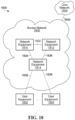
- the communication system 1800 is intended solely as an illustrative example.
- An access network 1802 could include more or fewer than three installations of network equipment, for example, which might or might not all directly communicate with each other as shown. Also, more than one installation of network equipment in the access network 1802 could provide communication service to user equipment. There could be more than one access network 1802 coupled to a core network 1804. It should also be appreciated that the present disclosure is not in any way limited to communication systems having an access network / core network structure.
- any of various implementations are possible.
- the exact structure of network equipment 1810, 1812, 1814, and user equipment 1822, 1824 for which such network equipment provides communication service, is implementation-dependent.
- the apparatus 1500, 1600, 1700 in Figs. 15 to 17 are examples of communication equipment that could be implemented at user equipment 1822, 1824 and/or network equipment 1810, 1812, 1814.
- At least the network equipment 1814 that provides communication service to the user equipment 1822, 1824 includes a physical interface and communications circuitry to support communications with the user equipment over the links 1838, 1839.
- the physical interface could be in the form of an antenna or an antenna array, for example, where the access communication links 1838, 1839 are wireless links. Multiple interfaces could be provided at the network equipment 1814 to support multiple access communication links 1838, 1839 of the same type or different types, for instance.
- the type of communications circuitry coupled to the physical interface or interfaces at the access network equipment 1814 is dependent upon the type or types of access communication links 1838, 1839 and the communication protocol or protocols used to communicate with the user equipment 1822, 1824.
- the network equipment 1810, 1812, 1814 also includes a physical interface, or possibly multiple physical interfaces, and communications circuitry to enable communications with other network equipment in the access network 1802. At least some installations of network equipment 1810, 1812, 1814 also include one or more physical interfaces and communications circuitry to enable communications with core network equipment over the communication link 1840. There could be multiple communication links between network equipment 1810, 1812, 1814 and the core network 1804. Communication links 1832, 1834, 1836 in the access network 1802, and the communication link 1840 to the core network 1804, could be the same type of communication link.
- the same type of physical interface and the same communications circuitry at the network equipment 1810, 1812, 1814 could support communications between access network equipment within the access network 1802 and between the access network 1802 and the core network 1804.
- Different physical interfaces and communications circuitry could instead be provided at the network equipment 1810, 1812, 1814 for communications within the access network 1802 and between the access network 1802 and the core network 1804.
Landscapes
- Engineering & Computer Science (AREA)
- Computer Networks & Wireless Communication (AREA)
- Signal Processing (AREA)
- Artificial Intelligence (AREA)
- Error Detection And Correction (AREA)
Claims (3)
- Verfahren, umfassend:Anwenden von Codierung mit binärer Vorwärtsfehlerkorrektur, FEC, (1402) auf einen Strom von eingegebenen binären Bits, um einen Strom von codierten Bits zu erzeugen;Abbilden (1406) des Stroms von codierten Bits auf eine Vielzahl von binären Strömen; undAnwenden von stromspezifischen Modulationen (1408) auf die Vielzahl von binären Strömen (1408), wobei die stromspezifischen Modulationen QAM-Abbildung und/oder stromspezifische Modulationen verschiedener Ordnungen umfassen, um eine Vielzahl von ersten komplexwertigen Strömen zu erzeugen,dadurch gekennzeichnet, dass das Verfahren ferner umfasst, nichtbinäre FEC-Codierung (1410) auf die erzeugte Vielzahl von ersten komplexwertigen Strömen anzuwenden, um einen zweiten komplexwertigen Strom zu erzeugen, wobei Anwenden von nichtbinärer FEC-Codierung eines oder beide von Folgendem umfasst:Verwürfelung auf Symbolebene und Verschachtelung auf Symbolebene, wobei bei der Verwürfelung auf Symbolebene jeder der Vielzahl von ersten komplexwertigen Strömen mit einer Verwürfelungssequenz multipliziert wird und wobei bei der Verschachtelung auf Symbolebene jeder der Vielzahl von ersten komplexwertigen Strömen mit einer Verschachtelungsmatrix multipliziert wird;wobei Anwenden von binärer FEC-Codierung umfasst, binäre FEC-Codierung auf Ströme von eingegebenen Bits, die mit mehreren UEs assoziiert sind, anzuwenden, um Ströme von codierten Bits zu erzeugen,wobei das Verfahren ferner Bitmultiplexing der Ströme von codierten Bits in einen bitgemultiplexten Strom von codierten Bits umfasst,wobei Abbilden Abbilden des bitgemultiplexten Stroms von codierten Bits umfasst.
- Nicht-flüchtiges computerlesbares Medium (1512, 1725), dafür konfiguriert, an einen Prozessor gekoppelt zu werden und Anweisungen zu speichern, die, wenn sie durch einen Prozessor ausgeführt werden, das Verfahren nach Anspruch 1 implementieren.
- Vorrichtung, umfassend:einen Prozessor (1504, 1705);ein nicht-flüchtiges computerlesbares Medium, das an den Prozessor (1504, 1705) gekoppelt ist und Anweisungen speichert, die, wenn sie durch den Prozessor ausgeführt werden, den Prozessor veranlassen, das Verfahren nach Anspruch 1 durchzuführen.
Applications Claiming Priority (2)
| Application Number | Priority Date | Filing Date | Title |
|---|---|---|---|
| US201662321628P | 2016-04-12 | 2016-04-12 | |
| PCT/CN2017/080098 WO2017177899A1 (en) | 2016-04-12 | 2017-04-11 | Methods and apparatus for signal spreading and multiplexing |
Publications (3)
| Publication Number | Publication Date |
|---|---|
| EP3427427A1 EP3427427A1 (de) | 2019-01-16 |
| EP3427427A4 EP3427427A4 (de) | 2019-08-21 |
| EP3427427B1 true EP3427427B1 (de) | 2025-07-02 |
Family
ID=60041418
Family Applications (1)
| Application Number | Title | Priority Date | Filing Date |
|---|---|---|---|
| EP17781875.4A Active EP3427427B1 (de) | 2016-04-12 | 2017-04-11 | Verfahren und vorrichtung zur signalspreizung und -multiplexierung |
Country Status (4)
| Country | Link |
|---|---|
| US (2) | US10432252B2 (de) |
| EP (1) | EP3427427B1 (de) |
| CN (1) | CN109075900B (de) |
| WO (1) | WO2017177899A1 (de) |
Families Citing this family (17)
| Publication number | Priority date | Publication date | Assignee | Title |
|---|---|---|---|---|
| WO2018019393A1 (en) * | 2016-07-29 | 2018-02-01 | Huawei Technologies Co., Ltd. | Encoding device and method and corresponding decoding device and method |
| US11695507B2 (en) * | 2017-03-24 | 2023-07-04 | Samsung Electronics Co., Ltd. | Apparatus and method for in multiple access in wireless communication |
| CN108809332B (zh) * | 2017-05-05 | 2021-09-03 | 华为技术有限公司 | 一种Polar码传输方法及装置 |
| US10763993B2 (en) * | 2017-11-06 | 2020-09-01 | Hughes Network Systems, Llc | System and method for asynchronous multi-stream transmission for NOMA |
| CN114244470B (zh) | 2017-11-17 | 2023-11-21 | 中兴通讯股份有限公司 | 信道状态信息csi编码方法及装置、存储介质和处理器 |
| US11171744B2 (en) | 2018-02-06 | 2021-11-09 | Apple Inc. | Uplink non-orthogonal multiple access transmission scheme |
| CN108512794B (zh) * | 2018-03-15 | 2021-05-07 | 中国科学院上海高等研究院 | 峰均比的降低方法、装置、计算机可读存储介质及设备 |
| US11115141B2 (en) | 2018-04-30 | 2021-09-07 | Nxp B.V. | Wired communications device and method for operating a wired communications device |
| US11108842B2 (en) * | 2018-04-30 | 2021-08-31 | Nxp B.V. | Wired communications device and method for operating a wired communications device |
| WO2020006738A1 (en) * | 2018-07-05 | 2020-01-09 | Huawei Technologies Co., Ltd. | Method and apparatus for wireless communications with unequal error protection |
| CN112753201B (zh) * | 2018-09-29 | 2022-12-20 | 中兴通讯股份有限公司 | 具有干扰抑制的多址接入方案 |
| CN110535800B (zh) * | 2019-02-01 | 2023-04-25 | 中兴通讯股份有限公司 | 一种数据处理方法及装置、计算机可读存储介质 |
| CN113949453B (zh) * | 2020-07-15 | 2023-04-11 | 华为技术有限公司 | 调制编码、解调译码的方法、装置、设备及通信系统 |
| CN112104440B (zh) * | 2020-09-08 | 2021-05-11 | 深圳市华智芯联科技有限公司 | 通信信号处理方法和无线通信系统 |
| US11424859B2 (en) | 2020-10-15 | 2022-08-23 | Hewlett Packard Enterprise Development Lp | Physical layer low-latency forward error correction |
| US11595152B1 (en) * | 2021-11-04 | 2023-02-28 | Nvidia Corporation | Forward error correction encoding using binary clustering |
| CN119537810B (zh) * | 2024-11-23 | 2025-08-08 | 山东省青岛生态环境监测中心(中国环境监测总站黄海近岸海域环境监测分站) | 生态环境多源数据智能采集与分析系统及其方法 |
Citations (2)
| Publication number | Priority date | Publication date | Assignee | Title |
|---|---|---|---|---|
| US6466564B1 (en) * | 1998-09-14 | 2002-10-15 | Terayon Communications Systems, Inc. | Two dimensional interleave process for CDMA transmissions of one dimensional timeslot data |
| US20140362701A1 (en) * | 2013-06-05 | 2014-12-11 | Texas Instruments Incorporated | Nlos wireless backhaul downlink communication |
Family Cites Families (38)
| Publication number | Priority date | Publication date | Assignee | Title |
|---|---|---|---|---|
| WO2002009300A2 (en) * | 2000-07-21 | 2002-01-31 | Catena Networks, Inc. | Method and system for turbo encoding in adsl |
| US6934317B1 (en) * | 2000-10-11 | 2005-08-23 | Ericsson Inc. | Systems and methods for communicating spread spectrum signals using variable signal constellations |
| US6574268B1 (en) * | 2000-11-21 | 2003-06-03 | Bbnt Solutions Llc | Asymmetric orthogonal codes for optical communications |
| US7071994B2 (en) * | 2001-01-04 | 2006-07-04 | Telisar Corporation | System and method for nondisruptively embedding an OFDM modulated data signal into a composite video signal |
| US7006483B2 (en) * | 2001-02-23 | 2006-02-28 | Ipr Licensing, Inc. | Qualifying available reverse link coding rates from access channel power setting |
| KR100566241B1 (ko) | 2001-11-19 | 2006-03-29 | 삼성전자주식회사 | 이동통신시스템에서 연성 심볼 결합 장치 및 방법 |
| US20080118003A1 (en) * | 2002-11-13 | 2008-05-22 | Industrial Technology Research Institute | Enhanced Wireless Communication System and Method Thereof |
| EP1615366A1 (de) * | 2004-07-08 | 2006-01-11 | Motorola, Inc. | Verfahren und Vorrichtung zum übertragen und empfängen eines Datensymbolstroms |
| WO2006014143A1 (en) * | 2004-08-03 | 2006-02-09 | Agency For Science, Technology And Research | Method for transmitting a digital data stream, transmitter, method for receiving a digital data stream and receiver |
| UA95992C2 (ru) * | 2006-11-06 | 2011-09-26 | Квелкомм Інкорпорейтед | Скремблирование на уровне кодового слова в мимо-передаче |
| CN101663843B (zh) * | 2007-03-21 | 2014-07-30 | 维尔塞特公司 | 用于在点波束卫星上提供广播业务的技术 |
| US20090080556A1 (en) | 2007-09-25 | 2009-03-26 | Chunjie Duan | Reducing Peak-to-Average-Power-Ratio in OFDM/OFDMA Signals by Deliberate Error Injection |
| WO2009041793A2 (en) * | 2007-09-28 | 2009-04-02 | Lg Electronics Inc. | Apparatus for transmitting and receiving a signal and method for transmitting and receiving a signal |
| US20090213946A1 (en) * | 2008-02-25 | 2009-08-27 | Xilinx, Inc. | Partial reconfiguration for a mimo-ofdm communication system |
| EP2139119A1 (de) * | 2008-06-25 | 2009-12-30 | Thomson Licensing | Serielle Verkettung von trelliskodierter Modulation und einem inneren nicht-binären LDPC Kode |
| US7975189B2 (en) * | 2008-11-14 | 2011-07-05 | Trelliware Technologies, Inc. | Error rate estimation/application to code-rate adaption |
| US8767856B2 (en) * | 2011-09-09 | 2014-07-01 | Intersil Americas LLC | Frame structure for a QAM system |
| KR101634188B1 (ko) * | 2009-02-12 | 2016-06-28 | 엘지전자 주식회사 | 신호 송수신 장치 및 방법 |
| KR20100120094A (ko) * | 2009-05-04 | 2010-11-12 | 한국전자통신연구원 | 위성 채널을 이용하는 데이터 송수신 방법 및 장치 |
| CA2776454C (en) * | 2009-09-30 | 2016-07-05 | Interdigital Patent Holdings, Inc. | Method and apparatus for multi-antenna transmission in uplink |
| GB2481051B (en) * | 2010-06-10 | 2016-06-01 | Samsung Electronics Co Ltd | Method for mapping and de-mapping of non-binary symbols in data communication systems |
| US8443269B2 (en) * | 2010-11-04 | 2013-05-14 | Himax Media Solutions, Inc. | System and method for handling forward error correction code blocks in a receiver |
| EP2479914B1 (de) * | 2011-01-21 | 2015-03-04 | Alcatel Lucent | Verfahren und Sendeelement zum Senden von Kanalinformationen zur Verbindungsanpassung, Verfahren und Empfängerelement zum Empfangen der Kanalinformationen |
| KR101868901B1 (ko) * | 2011-12-01 | 2018-07-23 | 한국전자통신연구원 | 디지털 방송 시스템에서 부가데이터 전송 및 수신을 위한 장치 및 방법 |
| WO2013170161A1 (en) * | 2012-05-11 | 2013-11-14 | Qualcomm Incorporated | System and method for uplink multiple input multiple output transmission |
| US9240853B2 (en) * | 2012-11-16 | 2016-01-19 | Huawei Technologies Co., Ltd. | Systems and methods for sparse code multiple access |
| CN103428158B (zh) * | 2012-12-12 | 2016-08-24 | 上海数字电视国家工程研究中心有限公司 | 数字信号发射装置、接收装置及调制、解调方法 |
| US20140229997A1 (en) * | 2013-02-08 | 2014-08-14 | Electronics And Telecommunications Research Institute | Satellite broadcasting and communication transmitting method and apparatus operable in broad signal to noise ratio (snr) environment |
| KR102061653B1 (ko) * | 2013-04-15 | 2020-02-11 | 삼성전자주식회사 | 무선 통신 시스템에서 비트 심볼 매핑 방법 및 장치 |
| US20140314137A1 (en) * | 2013-04-22 | 2014-10-23 | Ismail Lakkis | Method and Apparatus for a Single-Carrier Wireless Communication System |
| CN103843275B (zh) * | 2013-11-25 | 2017-02-22 | 华为技术有限公司 | 比特流的处理设备、处理方法和通信系统 |
| US9762360B2 (en) * | 2014-06-09 | 2017-09-12 | Allen LeRoy Limberg | Digital television broadcasting system using coded orthogonal frequency-division modulation with multilevel low-density-parity-check coding |
| US20150358648A1 (en) * | 2014-06-09 | 2015-12-10 | Allen LeRoy Limberg | Digital television broadcasting system using coded orthogonal frequency-division modulation and multilevel LDPC convolutional coding |
| US10218763B2 (en) * | 2015-05-08 | 2019-02-26 | Huawei Technologies Co., Ltd. | Method and system for low data rate transmission |
| US9654253B1 (en) * | 2015-12-21 | 2017-05-16 | Inphi Corporation | Apparatus and method for communicating data over an optical channel |
| US10736081B2 (en) * | 2016-09-14 | 2020-08-04 | Huawei Technologies Co., Ltd. | Non-orthogonal multiple access transmission |
| US10305633B2 (en) * | 2016-09-19 | 2019-05-28 | Qualcomm Incorporated | Per-symbol K-bit interleaver |
| US10630319B2 (en) * | 2017-01-24 | 2020-04-21 | Mediatek Inc. | Structure of interleaver with LDPC code |
-
2017
- 2017-04-11 EP EP17781875.4A patent/EP3427427B1/de active Active
- 2017-04-11 CN CN201780024268.0A patent/CN109075900B/zh active Active
- 2017-04-11 WO PCT/CN2017/080098 patent/WO2017177899A1/en not_active Ceased
-
2018
- 2018-09-06 US US16/123,895 patent/US10432252B2/en active Active
-
2019
- 2019-09-25 US US16/582,812 patent/US20200091962A1/en not_active Abandoned
Patent Citations (2)
| Publication number | Priority date | Publication date | Assignee | Title |
|---|---|---|---|---|
| US6466564B1 (en) * | 1998-09-14 | 2002-10-15 | Terayon Communications Systems, Inc. | Two dimensional interleave process for CDMA transmissions of one dimensional timeslot data |
| US20140362701A1 (en) * | 2013-06-05 | 2014-12-11 | Texas Instruments Incorporated | Nlos wireless backhaul downlink communication |
Also Published As
| Publication number | Publication date |
|---|---|
| EP3427427A4 (de) | 2019-08-21 |
| US20190007092A1 (en) | 2019-01-03 |
| CN109075900B (zh) | 2020-10-23 |
| CN109075900A (zh) | 2018-12-21 |
| US20200091962A1 (en) | 2020-03-19 |
| US10432252B2 (en) | 2019-10-01 |
| WO2017177899A1 (en) | 2017-10-19 |
| EP3427427A1 (de) | 2019-01-16 |
Similar Documents
| Publication | Publication Date | Title |
|---|---|---|
| EP3427427B1 (de) | Verfahren und vorrichtung zur signalspreizung und -multiplexierung | |
| US11043975B2 (en) | Encoding method, decoding method, apparatus, and system | |
| EP2377359B1 (de) | Verfahren und vorrichtung zur kodierung und dekodierung | |
| EP3172853B1 (de) | System und verfahren zur erzeugung von codebüchern mit kleinen projektionen pro komplexdimension und verwendung davon | |
| JP5940722B2 (ja) | 通信システムにおける多重コードブロックに対するcrcを計算するための方法及び装置 | |
| EP3434000B1 (de) | Verfahren zum entwerfen, übertragen und erfassen eines mehrfachzugriffscodebuchs durch flexible verstreute codes | |
| JP5647195B2 (ja) | 多重入出力システムにおけるチャンネル品質情報フィードバック方法、データ伝送方法、ユーザ機器及び基地局 | |
| EP3172857B1 (de) | System und verfahren zur erzeugung von wellenformen und verwendung davon | |
| KR101407073B1 (ko) | 다중입력 다중출력 시스템에서 상향링크 데이터용 물리 채널 영역으로 제어 정보를 전송하는 방법 | |
| US10158404B2 (en) | Data transmission method, transmit end device, and receive end device | |
| US10356788B2 (en) | System and method for high-rate sparse code multiple access in downlink | |
| US20180083666A1 (en) | Methods for multiple access transmission | |
| EP2159930A1 (de) | Funkkommunikationseinrichtung, funkkommunikationssystem und funkkommunikationsverfahren | |
| JP6357547B2 (ja) | インターリービング前に反復を、インターリービング後にパンクチャリングを実行する送信機デバイス及び受信機デバイス、並びにその方法 | |
| CA3057817A1 (en) | Method for performing encoding on basis of parity check matrix of low density parity check (ldpc) code in wireless communication system and terminal using same | |
| EP4165807B1 (de) | Transportblockgrössenbestimmung | |
| CN109981511B (zh) | 基于非正交多址的数据传输 | |
| KR101518831B1 (ko) | 통신시스템에서 순환중복검사 첨부를 위한 장치 | |
| US10098121B2 (en) | Iterative receiver and methods for decoding uplink wireless communications | |
| Sardar et al. | Performance analysis of MIMO—OFDM downlink with soft and hard decision decoding for 1/2 and 1/4 rate convolution encoder | |
| Fu et al. | A Precoding-Based Compute-and-Forward |
Legal Events
| Date | Code | Title | Description |
|---|---|---|---|
| STAA | Information on the status of an ep patent application or granted ep patent |
Free format text: STATUS: THE INTERNATIONAL PUBLICATION HAS BEEN MADE |
|
| PUAI | Public reference made under article 153(3) epc to a published international application that has entered the european phase |
Free format text: ORIGINAL CODE: 0009012 |
|
| STAA | Information on the status of an ep patent application or granted ep patent |
Free format text: STATUS: REQUEST FOR EXAMINATION WAS MADE |
|
| 17P | Request for examination filed |
Effective date: 20181008 |
|
| AK | Designated contracting states |
Kind code of ref document: A1 Designated state(s): AL AT BE BG CH CY CZ DE DK EE ES FI FR GB GR HR HU IE IS IT LI LT LU LV MC MK MT NL NO PL PT RO RS SE SI SK SM TR |
|
| AX | Request for extension of the european patent |
Extension state: BA ME |
|
| RIC1 | Information provided on ipc code assigned before grant |
Ipc: H04L 1/00 20060101AFI20190226BHEP |
|
| DAV | Request for validation of the european patent (deleted) | ||
| DAX | Request for extension of the european patent (deleted) | ||
| A4 | Supplementary search report drawn up and despatched |
Effective date: 20190719 |
|
| RIC1 | Information provided on ipc code assigned before grant |
Ipc: H04L 1/00 20060101AFI20190715BHEP |
|
| STAA | Information on the status of an ep patent application or granted ep patent |
Free format text: STATUS: EXAMINATION IS IN PROGRESS |
|
| 17Q | First examination report despatched |
Effective date: 20210203 |
|
| GRAP | Despatch of communication of intention to grant a patent |
Free format text: ORIGINAL CODE: EPIDOSNIGR1 |
|
| STAA | Information on the status of an ep patent application or granted ep patent |
Free format text: STATUS: GRANT OF PATENT IS INTENDED |
|
| INTG | Intention to grant announced |
Effective date: 20250213 |
|
| GRAS | Grant fee paid |
Free format text: ORIGINAL CODE: EPIDOSNIGR3 |
|
| GRAA | (expected) grant |
Free format text: ORIGINAL CODE: 0009210 |
|
| STAA | Information on the status of an ep patent application or granted ep patent |
Free format text: STATUS: THE PATENT HAS BEEN GRANTED |
|
| AK | Designated contracting states |
Kind code of ref document: B1 Designated state(s): AL AT BE BG CH CY CZ DE DK EE ES FI FR GB GR HR HU IE IS IT LI LT LU LV MC MK MT NL NO PL PT RO RS SE SI SK SM TR |
|
| REG | Reference to a national code |
Ref country code: GB Ref legal event code: FG4D |
|
| REG | Reference to a national code |
Ref country code: CH Ref legal event code: EP |
|
| REG | Reference to a national code |
Ref country code: DE Ref legal event code: R096 Ref document number: 602017090308 Country of ref document: DE |
|
| REG | Reference to a national code |
Ref country code: IE Ref legal event code: FG4D |
|
| REG | Reference to a national code |
Ref country code: NL Ref legal event code: MP Effective date: 20250702 |
|
| PG25 | Lapsed in a contracting state [announced via postgrant information from national office to epo] |
Ref country code: PT Free format text: LAPSE BECAUSE OF FAILURE TO SUBMIT A TRANSLATION OF THE DESCRIPTION OR TO PAY THE FEE WITHIN THE PRESCRIBED TIME-LIMIT Effective date: 20251103 |
|
| PG25 | Lapsed in a contracting state [announced via postgrant information from national office to epo] |
Ref country code: NL Free format text: LAPSE BECAUSE OF FAILURE TO SUBMIT A TRANSLATION OF THE DESCRIPTION OR TO PAY THE FEE WITHIN THE PRESCRIBED TIME-LIMIT Effective date: 20250702 |
|
| REG | Reference to a national code |
Ref country code: AT Ref legal event code: MK05 Ref document number: 1810492 Country of ref document: AT Kind code of ref document: T Effective date: 20250702 |