EP3426440B1 - Tightening device for tightening pipe connection - Google Patents
Tightening device for tightening pipe connection Download PDFInfo
- Publication number
- EP3426440B1 EP3426440B1 EP16893353.9A EP16893353A EP3426440B1 EP 3426440 B1 EP3426440 B1 EP 3426440B1 EP 16893353 A EP16893353 A EP 16893353A EP 3426440 B1 EP3426440 B1 EP 3426440B1
- Authority
- EP
- European Patent Office
- Prior art keywords
- rotation
- tightening device
- drive
- socket member
- reciprocating member
- Prior art date
- Legal status (The legal status is an assumption and is not a legal conclusion. Google has not performed a legal analysis and makes no representation as to the accuracy of the status listed.)
- Active
Links
Images


Classifications
-
- B—PERFORMING OPERATIONS; TRANSPORTING
- B25—HAND TOOLS; PORTABLE POWER-DRIVEN TOOLS; MANIPULATORS
- B25B—TOOLS OR BENCH DEVICES NOT OTHERWISE PROVIDED FOR, FOR FASTENING, CONNECTING, DISENGAGING OR HOLDING
- B25B21/00—Portable power-driven screw or nut setting or loosening tools; Attachments for drilling apparatus serving the same purpose
- B25B21/004—Portable power-driven screw or nut setting or loosening tools; Attachments for drilling apparatus serving the same purpose of the ratchet type
-
- B—PERFORMING OPERATIONS; TRANSPORTING
- B25—HAND TOOLS; PORTABLE POWER-DRIVEN TOOLS; MANIPULATORS
- B25B—TOOLS OR BENCH DEVICES NOT OTHERWISE PROVIDED FOR, FOR FASTENING, CONNECTING, DISENGAGING OR HOLDING
- B25B13/00—Spanners; Wrenches
- B25B13/46—Spanners; Wrenches of the ratchet type, for providing a free return stroke of the handle
- B25B13/461—Spanners; Wrenches of the ratchet type, for providing a free return stroke of the handle with concentric driving and driven member
- B25B13/466—Spanners; Wrenches of the ratchet type, for providing a free return stroke of the handle with concentric driving and driven member the ratchet parts engaging in an axial direction
-
- B—PERFORMING OPERATIONS; TRANSPORTING
- B25—HAND TOOLS; PORTABLE POWER-DRIVEN TOOLS; MANIPULATORS
- B25B—TOOLS OR BENCH DEVICES NOT OTHERWISE PROVIDED FOR, FOR FASTENING, CONNECTING, DISENGAGING OR HOLDING
- B25B13/00—Spanners; Wrenches
- B25B13/48—Spanners; Wrenches for special purposes
-
- B—PERFORMING OPERATIONS; TRANSPORTING
- B25—HAND TOOLS; PORTABLE POWER-DRIVEN TOOLS; MANIPULATORS
- B25B—TOOLS OR BENCH DEVICES NOT OTHERWISE PROVIDED FOR, FOR FASTENING, CONNECTING, DISENGAGING OR HOLDING
- B25B13/00—Spanners; Wrenches
- B25B13/48—Spanners; Wrenches for special purposes
- B25B13/50—Spanners; Wrenches for special purposes for operating on work of special profile, e.g. pipes
- B25B13/5008—Spanners; Wrenches for special purposes for operating on work of special profile, e.g. pipes for operating on pipes or cylindrical objects
- B25B13/5016—Spanners; Wrenches for special purposes for operating on work of special profile, e.g. pipes for operating on pipes or cylindrical objects by externally gripping the pipe
- B25B13/5025—Spanners; Wrenches for special purposes for operating on work of special profile, e.g. pipes for operating on pipes or cylindrical objects by externally gripping the pipe using a pipe wrench type tool
- B25B13/5033—Spanners; Wrenches for special purposes for operating on work of special profile, e.g. pipes for operating on pipes or cylindrical objects by externally gripping the pipe using a pipe wrench type tool with fixed jaws
-
- B—PERFORMING OPERATIONS; TRANSPORTING
- B25—HAND TOOLS; PORTABLE POWER-DRIVEN TOOLS; MANIPULATORS
- B25B—TOOLS OR BENCH DEVICES NOT OTHERWISE PROVIDED FOR, FOR FASTENING, CONNECTING, DISENGAGING OR HOLDING
- B25B23/00—Details of, or accessories for, spanners, wrenches, screwdrivers
-
- B—PERFORMING OPERATIONS; TRANSPORTING
- B25—HAND TOOLS; PORTABLE POWER-DRIVEN TOOLS; MANIPULATORS
- B25B—TOOLS OR BENCH DEVICES NOT OTHERWISE PROVIDED FOR, FOR FASTENING, CONNECTING, DISENGAGING OR HOLDING
- B25B23/00—Details of, or accessories for, spanners, wrenches, screwdrivers
- B25B23/0085—Counterholding devices
Definitions
- the present invention relates to a tightening device for tightening a pipe connection.
- a known pipe connection comprises a tube, a cutting ring, a connector nut and a connector body.
- a thread of the connector body is adapted to co-operate with a thread of the connector nut.
- An example of such a pipe connection is disclosed in the standard DIN 2353.
- a known method for tightening a pipe connection comprises using two open-ended spanners.
- a first open-ended spanner is used to rotate a connector nut of a pipe connection while a second open-ended spanner is used to retain a connector body of the pipe connection. It should be noted that in a general case it is not possible to use ring spanners because of a pipe or pipes of the pipe connection.
- An object of the present invention is to provide a tightening device for tightening a pipe connection so as to solve the above problem.
- the object of the invention is achieved by a tightening device which is characterized by what is stated in the independent claim 1.
- the preferred embodiments of the invention are disclosed in the dependent claims.
- the invention is based on the idea of providing a tightening device with an open sided socket member rotated by a reciprocating member adapted to reciprocate between two positions by pivoting about an axis of rotation that coincides with an axis of rotation of the open sided socket member.
- An advantage of the tightening device of the invention is that there is no need to disengage and engage the tightening device repeatedly even when a connector nut is rotated several full turns and there is limited space around the pipe connection to be tightened. A frame of the tightening device does not rotate relative to the connector body during a tightening process.
- a tightening device of the invention is adapted to be connected to a torque wrench thereby allowing an accurate control of the tightening torque of the tightening device. Such control cannot be realized in a known tightening method utilizing two open-ended spanners.
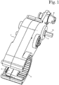
- FIG. 1 shows a tightening device according to an embodiment of the invention.
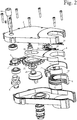
- Figure 2 is an exploded view of the tightening device of Figure 1 .
- the tightening device of Figure 1 comprises a frame 2, a reciprocating member 4 adapted to reciprocate between a first position and a second position relative to the frame 2 by pivoting about a first axis of rotation, power input means 5 for inputting mechanical power into the tightening device, drive system for transferring driving force from the power input means 5 to the reciprocating member 4 and a socket member 6 adapted for rotating a connector nut of a pipe connection, the socket member 6 being adapted to be rotated relative to the frame 2 about a rotation axis of the socket member 6, the rotation axis of the socket member 6 coinciding with the first axis of rotation.
- the tightening device only partially surrounds the first axis of rotation.
- the socket member 6 has an open side for enabling accessing the rotation axis of the socket member 6 from a radial direction. Further, the entire tightening device has an open side for enabling accessing the first axis of rotation from a radial direction.
- the radial direction is a direction perpendicular to the axis in question.
- a socket member 6 comprises a replaceable socket bit adapted to engage a connector nut of a pipe connection, the socket bit having an open side.
- the power input means 5 are adapted to be connected to a torque wrench selectively on either side of the frame 2 in axial direction.
- the power input means 5 comprises a pipe shaft accessible from both sides of the frame 2, and a detachable adapter element 55 adapted to be in power transmission connection with the pipe shaft. Rotation axis of the pipe shaft is parallel to the first axis of rotation.
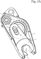
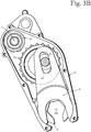
- Figures 3A and 3B illustrate the drive system of the tightening device of Figure 1 .
- the tightening device is in a partially disassembled state.
- the reciprocating member 4 is in the first position relative to the frame 2.
- the reciprocating member 4 is in the second position relative to the frame 2.
- the first axis of rotation about which the reciprocating member 4 reciprocates, is denoted with reference numeral 101.
- the drive system has a transmission ratio adapted to increase torque between the power input means 5 and the reciprocating member 4.
- the drive system comprises a drive slot 46 provided on the reciprocating member 4, a first drive gear 21, a second drive gear 22 and a chain adapted to transfer power from the second drive gear 22 to the first drive gear 21.
- the second drive gear 22 has fewer teeth than the first drive gear 21. In Figures 3A and 3B neither the chain nor teeth of the second drive gear 22 are shown.
- the first drive gear 21 is adapted to be rotated relative to the frame 2 about a rotation axis which is parallel to and spaced apart from the first axis of rotation 101.
- the first drive gear 21 is provided with a drive pin 26 on a surface of the first drive gear 21 extending perpendicular to the first axis of rotation 101.
- a centre of the drive pin 26 is located at a distance from the rotation axis of the first drive gear 21.
- the drive slot 46 is adapted to co-operate with the drive pin 26 for transferring driving force from the first drive gear 21 to the reciprocating member 4 such that unidirectional rotation of the first drive gear 21 provides reciprocation of the reciprocating member 4 between the first position and the second position relative to the frame 2.
- the co-operation is realized such that the drive pin 26 is received in the drive slot 46.
- the drive slot 46 extends substantially linearly in a direction perpendicular to the first axis of rotation 101.
- the drive slot 46 is spaced apart from the first axis of rotation 101.
- the drive pin 26 is adapted to move between a first pin position and a second pin position in the drive slot 46 relative to the reciprocating member 4.
- a distance between the first pin position and the second pin position equals a travel of pin.
- Figures 3A and 3B show that the drive pin 26 is situated in a middle region of the travel of pin both in the first position and the second position of the reciprocating member 4, the middle region being the middle third of the travel of pin.
- a drive coupling between the reciprocating member 4 and the socket member 6 is adapted for transferring driving force from the reciprocating member 4 to the socket member 6 in a first direction of rotation, and to prevent transfer of driving force from the reciprocating member 4 to the socket member 6 in a second direction of rotation opposite to the first direction of rotation, such that during use of the tightening device a reciprocating motion of the reciprocating member 4 between the first position and the second position provides unidirectional rotation of the socket member 6 in the first direction of rotation.
- the drive coupling comprises first tooth means on a drive surface of the reciprocating member 4, and second tooth means on a drive surface of the socket member 6.
- the first tooth means comprise a plurality of first teeth 41
- the second tooth means comprise a plurality of second teeth 62.
- Both the drive surface of the reciprocating member 4 and the drive surface of the socket member 6 extend perpendicular to the first axis of rotation 101.
- the second tooth means are adapted to co-operate with the first tooth means for transferring driving force from the reciprocating member 4 to the socket member 6.
- the drive coupling between the reciprocating member 4 and the socket member 6 is adapted to allow axial movement between the first tooth means and the second tooth means in order to enable disengaging the first tooth means from transmission engagement with the second tooth means during rotation of the reciprocating member 4 in the second direction of rotation.
- the reciprocating member 4 is adapted to move axially relative to the frame 2 for disengaging the first tooth means from the second tooth means.
- axial direction is a direction parallel to the first axis of rotation 101.
- the drive coupling comprises pressing means for pressing the reciprocating member 4 towards the socket member 6.
- the pressing means are adapted to axially return the first tooth means from a disengaged position to an engaged position with relation to the second tooth means by exerting an axial force to the reciprocating member 4 towards the socket member 6.
- the pressing means comprise a flat spring element 32 between the frame 2 and the reciprocating member 4.
- the flat spring element 32 comprises eight flat spring members 34 protruding from a body part 36.
- the pressing means comprise at least one coil spring between the frame and the reciprocating member.
- the pressing means comprise at least one magnet.
- a drive coupling between a reciprocating member and a socket member comprises a first friction surface on the reciprocating member, and a second friction surface on the socket member.
- the first friction surface is located on a drive surface of the reciprocating member that extends perpendicular to the first axis of rotation.
- the second friction surface is located on a drive surface of the socket member that extends perpendicular to the first axis of rotation.
- the pressing means can comprise a hydraulic pressing mechanism which is adapted to be in a pressing state during movement of the reciprocating member in the first direction of rotation, and in a released state during movement of the reciprocating member in the second direction of rotation.
- Both directions of rotation of the first drive gear 21 are adapted to provide unidirectional rotation of the socket member 6 in the first direction of rotation.
- the tightening device of Figure 1 is optimized for rotating the first drive gear 21 in the same direction as the socket member 6.
- Figures 4A and 4B are sectional views of the tightening device of Figure 1 as seen from a direction perpendicular to the first axis of rotation.
- the first tooth means of the reciprocating member 4 are in transmission engagement with the second tooth means of the of the socket member 6.
- Figure 4B the first tooth means of the reciprocating member 4 are in a disengaged position relative to the second tooth means of the of the socket member 6.
- an axial distance between the reciprocating member 4 and the socket member 6 is greater than in Figure 4A .
- the pressing means press the reciprocating member 4 towards the socket member 6.
- the socket member 6 does not move axially relative to the frame 2.
- Figure 5 shows an enlargement of a second tooth 62 of the socket member 6.
- the second tooth 62 is an asymmetric tooth.
- a pressure angle ⁇ 1 of surface 621 of the second tooth 62 that co-operates for transferring driving force from the reciprocating member 4 to the socket member 6 in the first direction of rotation is substantially smaller than a pressure angle ⁇ 2 of surface 622 of the second tooth 62 that co-operate for transferring force from the reciprocating member 4 to the socket member 6 in the second direction of rotation.
- the pressure angle ⁇ 1 is -2° and the pressure angle ⁇ 2 is 70°. Pressure angles of the first teeth 41 are matched with the pressure angles ⁇ 1 and ⁇ 2 of the second teeth 62.
- pressure angles of surfaces adapted for transferring driving force from the reciprocating member to the socket member in the first direction of rotation are in the range of -0.5° to -5°.
- Difference between the pressure angles ⁇ 2 and ⁇ 1 is 72°.
- difference between the pressure angles of surfaces adapted for transferring force from the reciprocating member to the socket member in the second and first directions is in the range of 30° to 85°.
- the large positive value of the pressure angle ⁇ 2 prevents transfer of driving force from the reciprocating member 4 to the socket member 6 in the second direction of rotation.
- preventing transfer of driving force means that the drive coupling between the reciprocating member 4 and the socket member 6 is capable of transferring a fraction of torque through the surface 622 and a counter surface thereof when compared with the torque the drive coupling is capable of transferring through the surface 621 and a counter surface thereof.
- Said fraction of torque can be one fifth or less, for example. Consequently the drive coupling is adapted to transfer a significantly higher torque in the first direction of rotation compared with the second direction of rotation.
- design of the pressing means affects torque transfer capability of the drive coupling.
- stiffness of the flat spring element 32 affects torque transfer capability of the drive coupling. Designing the spring element stiffer allows the drive coupling to transfer more torque in the second direction of rotation.
- the tightening device comprises a ratchet mechanism 7 adapted to allow rotation of the socket member 6 in the first direction of rotation, and to prevent rotation of the socket member 6 in the second direction of rotation.
- Figure 6 shows a sectional view of the ratchet mechanism 7 from a direction parallel to the first axis of rotation.
- the ratchet mechanism 7 comprises a plurality of ratchet teeth 72 provided on the socket member 6 and three pawls 74 adapted to co-operate with the plurality of ratchet teeth 72.
- the ratchet mechanism 7 also comprises a pawl spring for each pawl 74. The pawl springs are not shown in the Figures. In Figure 6 the first direction of rotation is clockwise.
- An angle between adjacent ratchet teeth 72 is equal to an angle between adjacent second teeth 62.
- the angle between adjacent ratchet teeth 72 is 10°.
- the ratchet teeth 72 are offset relative to the second teeth 62.
- An offset angle between the ratchet teeth 72 and the second teeth 62 is 3°.
- an offset angle between ratchet teeth and second teeth is in the range of 1° to 5°.
- the offset angle is adapted to allow the socket member 6 to rotate slightly in the second direction of rotation after the first tooth means have disengaged from the transmission engagement with the second tooth means.
- An appropriate offset angle relieves tension between a tightening device assembly and a pipe connection tightened by the tightening device assembly, and therefore facilitates disconnecting a tightening device from a pipe connection after the pipe connection has been tightened by the tightening device.
- the ratchet teeth 72 are located on a peripheral surface of the socket member 6 extending perpendicular to a radial direction of the socket member 6.
- second teeth on a drive surface of a socket member extending perpendicular to the first axis of rotation are adapted to function as ratchet teeth.
- Figure 7 illustrates tightening of a high-pressure pipe connection of a hydraulic system with a tightening device assembly comprising the tightening device of Figure 1 , and a locking member 10 fastened to the tightening device.
- the pipe connection shown in Figure 7 comprises a connector body 51 having a connector body thread, and a connector nut 52 having a nut thread adapted to co-operate with the connector body thread.
- Pipes connected to the connector body 51 are denoted with reference numerals 301, 302 and 303.
- the locking member 10 is in contact with the connector body 51, and the socket member 6 is in contact with the connector nut 52.
- the socket member 6 is adapted for rotating the connector nut 52.
- the locking member 10 co-operates with the socket member 6 for tightening the pipe connection such that the locking member 10 retains the connector body 51 of the pipe connection such that rotation of the connector body 51 is prevented relative to the frame 2.
- a centre line of the pipe 301 coincides with the rotation axis of the socket member 6, and therefore also with the first axis of rotation. During tightening of the pipe connection the frame 2 of the tightening device does not rotate relative to the pipe 301.
- the locking member 10 is detached from the tightening device. Then the tightening device is moved farther from the connector body 51 in axial direction such that the socket member 6 is no longer in contact with the connector nut 52. If the socket member 6 is in a disadvantageous position hindering detaching the tightening device from the pipe 301, the socket member 6 is rotated to a better position relative to the frame 2 by inputting power to the tightening device through the power input means 5. Finally, the tightening device is moved away from the pipe 301.
Landscapes
- Engineering & Computer Science (AREA)
- Mechanical Engineering (AREA)
- Orthopedics, Nursing, And Contraception (AREA)
- Hand Tools For Fitting Together And Separating, Or Other Hand Tools (AREA)
- Details Of Spanners, Wrenches, And Screw Drivers And Accessories (AREA)
- Clamps And Clips (AREA)
Priority Applications (1)
| Application Number | Priority Date | Filing Date | Title |
|---|---|---|---|
| PL16893353T PL3426440T3 (pl) | 2016-03-11 | 2016-03-11 | Urządzenie zaciskowe do dokręcania połączenia rurowego |
Applications Claiming Priority (1)
| Application Number | Priority Date | Filing Date | Title |
|---|---|---|---|
| PCT/FI2016/050153 WO2017153629A1 (en) | 2016-03-11 | 2016-03-11 | Tightening device for tightening pipe connection |
Publications (3)
| Publication Number | Publication Date |
|---|---|
| EP3426440A1 EP3426440A1 (en) | 2019-01-16 |
| EP3426440A4 EP3426440A4 (en) | 2019-03-13 |
| EP3426440B1 true EP3426440B1 (en) | 2021-01-06 |
Family
ID=59789029
Family Applications (1)
| Application Number | Title | Priority Date | Filing Date |
|---|---|---|---|
| EP16893353.9A Active EP3426440B1 (en) | 2016-03-11 | 2016-03-11 | Tightening device for tightening pipe connection |
Country Status (6)
| Country | Link |
|---|---|
| US (1) | US10821576B2 (pl) |
| EP (1) | EP3426440B1 (pl) |
| JP (1) | JP6689417B2 (pl) |
| ES (1) | ES2856648T3 (pl) |
| PL (1) | PL3426440T3 (pl) |
| WO (1) | WO2017153629A1 (pl) |
Families Citing this family (4)
| Publication number | Priority date | Publication date | Assignee | Title |
|---|---|---|---|---|
| WO2020086449A1 (en) | 2018-10-26 | 2020-04-30 | Milwaukee Electric Tool Corporation | Ratcheting tool |
| IL266295B2 (en) | 2019-04-28 | 2024-02-01 | Ham Let Israel Canada Ltd | key |
| DE202020101932U1 (de) * | 2020-04-08 | 2020-11-16 | GEDORE Holding GmbH | Werkzeug zur Montage und/oder Demontage einer an beiden Enden verschraubten Stange |
| US12042907B2 (en) * | 2021-06-25 | 2024-07-23 | Nissan North America, Inc. | Fastening tool |
Citations (1)
| Publication number | Priority date | Publication date | Assignee | Title |
|---|---|---|---|---|
| US5953966A (en) * | 1997-11-06 | 1999-09-21 | Spirer; Steven E | Hand wrench with torque augmenting means |
Family Cites Families (9)
| Publication number | Priority date | Publication date | Assignee | Title |
|---|---|---|---|---|
| US6148695A (en) * | 1999-08-03 | 2000-11-21 | Hu; Bobby | Ratchet wheel with asymmetric arcuate concave teeth or non-arcuate concave teeth and ratcheting tools with such ratchet wheel |
| JP4060586B2 (ja) | 2001-12-26 | 2008-03-12 | 本田技研工業株式会社 | 締付け工具 |
| US7454997B2 (en) * | 2003-01-08 | 2008-11-25 | Snap-On Incorporated | Axial pawl ratchet mechanism |
| KR100758924B1 (ko) * | 2005-09-09 | 2007-09-14 | 주식회사 동은전자 | 원심분리식 전동 임팩트 렌치 |
| US7631580B2 (en) * | 2007-11-13 | 2009-12-15 | Gm Global Technology Operations, Inc. | Wrench for tightening pipe nuts |
| US8584555B2 (en) * | 2011-08-11 | 2013-11-19 | Shu-Su Chan | Open-end ratchet wrench |
| US9333630B2 (en) * | 2013-08-19 | 2016-05-10 | Leon Robert Palmer | Dual-drive, self-ratcheting, mechanism with multiple input ports |
| DE112014006485T5 (de) * | 2014-03-19 | 2016-12-15 | Jim LAI | Ratsche |
| TWI571361B (zh) | 2014-09-16 | 2017-02-21 | Hou-Fei Hu | Electric sleeve ratchet wrench |
-
2016
- 2016-03-11 ES ES16893353T patent/ES2856648T3/es active Active
- 2016-03-11 WO PCT/FI2016/050153 patent/WO2017153629A1/en not_active Ceased
- 2016-03-11 US US16/083,629 patent/US10821576B2/en active Active
- 2016-03-11 EP EP16893353.9A patent/EP3426440B1/en active Active
- 2016-03-11 JP JP2018566648A patent/JP6689417B2/ja active Active
- 2016-03-11 PL PL16893353T patent/PL3426440T3/pl unknown
Patent Citations (1)
| Publication number | Priority date | Publication date | Assignee | Title |
|---|---|---|---|---|
| US5953966A (en) * | 1997-11-06 | 1999-09-21 | Spirer; Steven E | Hand wrench with torque augmenting means |
Also Published As
| Publication number | Publication date |
|---|---|
| JP6689417B2 (ja) | 2020-04-28 |
| WO2017153629A1 (en) | 2017-09-14 |
| EP3426440A1 (en) | 2019-01-16 |
| EP3426440A4 (en) | 2019-03-13 |
| US20190061115A1 (en) | 2019-02-28 |
| ES2856648T3 (es) | 2021-09-27 |
| JP2019512405A (ja) | 2019-05-16 |
| US10821576B2 (en) | 2020-11-03 |
| PL3426440T3 (pl) | 2021-06-14 |
Similar Documents
| Publication | Publication Date | Title |
|---|---|---|
| EP3426440B1 (en) | Tightening device for tightening pipe connection | |
| EP2321094B1 (en) | Line wrenches | |
| US9833883B2 (en) | Bi-directional screwdriver | |
| US8613350B2 (en) | Infinitely variable wrench | |
| JP6746792B2 (ja) | トルク伝達方向変更機構 | |
| US9140317B2 (en) | Wrench ratchet mechanisms and wrenches | |
| US7967683B2 (en) | Stabilizing mechanism for output torque of a transmission member | |
| JP4943397B2 (ja) | 流体作動トルクレンチ | |
| US7062992B2 (en) | Constant rotation rotary torque multiplier | |
| US20060102442A1 (en) | Torque transmission mechanism | |
| US7416375B2 (en) | Threaded coupling mechanism having quick engaging and disengaging feature | |
| US10288109B2 (en) | Self-locking screwing attachment device and assembly provided with same | |
| US20190022831A1 (en) | Ratchet Wrenches | |
| US20190210199A1 (en) | Screwdriver and ratchet mechanism thereof | |
| WO2018175881A1 (en) | Continuous rotation torque wrench | |
| CN100579696C (zh) | 具有进一步锁紧功能的钻夹头 | |
| WO2001010601A1 (en) | Dual-pawl full engagement reversible ratchet wrench | |
| CN110997240A (zh) | 具有自调节适配器的扭矩扳手 | |
| US8904906B2 (en) | Wrench | |
| US11491613B2 (en) | High-torque ratchet wrench | |
| KR20180109935A (ko) | 나사산형 체결구를 조이기 위한 장치 | |
| TWM673694U (zh) | 單向棘輪扳手 |
Legal Events
| Date | Code | Title | Description |
|---|---|---|---|
| STAA | Information on the status of an ep patent application or granted ep patent |
Free format text: STATUS: THE INTERNATIONAL PUBLICATION HAS BEEN MADE |
|
| PUAI | Public reference made under article 153(3) epc to a published international application that has entered the european phase |
Free format text: ORIGINAL CODE: 0009012 |
|
| STAA | Information on the status of an ep patent application or granted ep patent |
Free format text: STATUS: REQUEST FOR EXAMINATION WAS MADE |
|
| 17P | Request for examination filed |
Effective date: 20181002 |
|
| AK | Designated contracting states |
Kind code of ref document: A1 Designated state(s): AL AT BE BG CH CY CZ DE DK EE ES FI FR GB GR HR HU IE IS IT LI LT LU LV MC MK MT NL NO PL PT RO RS SE SI SK SM TR |
|
| AX | Request for extension of the european patent |
Extension state: BA ME |
|
| A4 | Supplementary search report drawn up and despatched |
Effective date: 20190212 |
|
| RIC1 | Information provided on ipc code assigned before grant |
Ipc: B25B 21/00 20060101AFI20190206BHEP Ipc: B25B 13/46 20060101ALI20190206BHEP Ipc: B25B 13/48 20060101ALI20190206BHEP Ipc: B25B 7/12 20060101ALI20190206BHEP Ipc: B25B 28/00 20060101ALI20190206BHEP Ipc: B25B 23/00 20060101ALI20190206BHEP |
|
| DAV | Request for validation of the european patent (deleted) | ||
| DAX | Request for extension of the european patent (deleted) | ||
| RIC1 | Information provided on ipc code assigned before grant |
Ipc: B25B 13/46 20060101ALI20200716BHEP Ipc: B25B 13/48 20060101ALI20200716BHEP Ipc: B25B 21/00 20060101AFI20200716BHEP Ipc: B25B 23/00 20060101ALI20200716BHEP Ipc: B25B 28/00 20060101ALI20200716BHEP Ipc: B25B 7/12 20060101ALI20200716BHEP |
|
| GRAP | Despatch of communication of intention to grant a patent |
Free format text: ORIGINAL CODE: EPIDOSNIGR1 |
|
| STAA | Information on the status of an ep patent application or granted ep patent |
Free format text: STATUS: GRANT OF PATENT IS INTENDED |
|
| INTG | Intention to grant announced |
Effective date: 20200902 |
|
| GRAS | Grant fee paid |
Free format text: ORIGINAL CODE: EPIDOSNIGR3 |
|
| GRAA | (expected) grant |
Free format text: ORIGINAL CODE: 0009210 |
|
| STAA | Information on the status of an ep patent application or granted ep patent |
Free format text: STATUS: THE PATENT HAS BEEN GRANTED |
|
| AK | Designated contracting states |
Kind code of ref document: B1 Designated state(s): AL AT BE BG CH CY CZ DE DK EE ES FI FR GB GR HR HU IE IS IT LI LT LU LV MC MK MT NL NO PL PT RO RS SE SI SK SM TR |
|
| REG | Reference to a national code |
Ref country code: GB Ref legal event code: FG4D |
|
| REG | Reference to a national code |
Ref country code: AT Ref legal event code: REF Ref document number: 1351849 Country of ref document: AT Kind code of ref document: T Effective date: 20210115 Ref country code: CH Ref legal event code: EP |
|
| REG | Reference to a national code |
Ref country code: DE Ref legal event code: R096 Ref document number: 602016051246 Country of ref document: DE |
|
| REG | Reference to a national code |
Ref country code: IE Ref legal event code: FG4D |
|
| REG | Reference to a national code |
Ref country code: FI Ref legal event code: FGE |
|
| REG | Reference to a national code |
Ref country code: NL Ref legal event code: MP Effective date: 20210106 |
|
| REG | Reference to a national code |
Ref country code: NO Ref legal event code: T2 Effective date: 20210106 |
|
| REG | Reference to a national code |
Ref country code: AT Ref legal event code: MK05 Ref document number: 1351849 Country of ref document: AT Kind code of ref document: T Effective date: 20210106 |
|
| REG | Reference to a national code |
Ref country code: LT Ref legal event code: MG9D |
|
| PG25 | Lapsed in a contracting state [announced via postgrant information from national office to epo] |
Ref country code: HR Free format text: LAPSE BECAUSE OF FAILURE TO SUBMIT A TRANSLATION OF THE DESCRIPTION OR TO PAY THE FEE WITHIN THE PRESCRIBED TIME-LIMIT Effective date: 20210106 Ref country code: GR Free format text: LAPSE BECAUSE OF FAILURE TO SUBMIT A TRANSLATION OF THE DESCRIPTION OR TO PAY THE FEE WITHIN THE PRESCRIBED TIME-LIMIT Effective date: 20210407 Ref country code: PT Free format text: LAPSE BECAUSE OF FAILURE TO SUBMIT A TRANSLATION OF THE DESCRIPTION OR TO PAY THE FEE WITHIN THE PRESCRIBED TIME-LIMIT Effective date: 20210506 Ref country code: BG Free format text: LAPSE BECAUSE OF FAILURE TO SUBMIT A TRANSLATION OF THE DESCRIPTION OR TO PAY THE FEE WITHIN THE PRESCRIBED TIME-LIMIT Effective date: 20210406 Ref country code: LT Free format text: LAPSE BECAUSE OF FAILURE TO SUBMIT A TRANSLATION OF THE DESCRIPTION OR TO PAY THE FEE WITHIN THE PRESCRIBED TIME-LIMIT Effective date: 20210106 |
|
| PG25 | Lapsed in a contracting state [announced via postgrant information from national office to epo] |
Ref country code: AT Free format text: LAPSE BECAUSE OF FAILURE TO SUBMIT A TRANSLATION OF THE DESCRIPTION OR TO PAY THE FEE WITHIN THE PRESCRIBED TIME-LIMIT Effective date: 20210106 Ref country code: RS Free format text: LAPSE BECAUSE OF FAILURE TO SUBMIT A TRANSLATION OF THE DESCRIPTION OR TO PAY THE FEE WITHIN THE PRESCRIBED TIME-LIMIT Effective date: 20210106 Ref country code: LV Free format text: LAPSE BECAUSE OF FAILURE TO SUBMIT A TRANSLATION OF THE DESCRIPTION OR TO PAY THE FEE WITHIN THE PRESCRIBED TIME-LIMIT Effective date: 20210106 Ref country code: SE Free format text: LAPSE BECAUSE OF FAILURE TO SUBMIT A TRANSLATION OF THE DESCRIPTION OR TO PAY THE FEE WITHIN THE PRESCRIBED TIME-LIMIT Effective date: 20210106 |
|
| REG | Reference to a national code |
Ref country code: ES Ref legal event code: FG2A Ref document number: 2856648 Country of ref document: ES Kind code of ref document: T3 Effective date: 20210927 |
|
| PG25 | Lapsed in a contracting state [announced via postgrant information from national office to epo] |
Ref country code: IS Free format text: LAPSE BECAUSE OF FAILURE TO SUBMIT A TRANSLATION OF THE DESCRIPTION OR TO PAY THE FEE WITHIN THE PRESCRIBED TIME-LIMIT Effective date: 20210506 |
|
| REG | Reference to a national code |
Ref country code: DE Ref legal event code: R097 Ref document number: 602016051246 Country of ref document: DE |
|
| PG25 | Lapsed in a contracting state [announced via postgrant information from national office to epo] |
Ref country code: SM Free format text: LAPSE BECAUSE OF FAILURE TO SUBMIT A TRANSLATION OF THE DESCRIPTION OR TO PAY THE FEE WITHIN THE PRESCRIBED TIME-LIMIT Effective date: 20210106 Ref country code: EE Free format text: LAPSE BECAUSE OF FAILURE TO SUBMIT A TRANSLATION OF THE DESCRIPTION OR TO PAY THE FEE WITHIN THE PRESCRIBED TIME-LIMIT Effective date: 20210106 Ref country code: CZ Free format text: LAPSE BECAUSE OF FAILURE TO SUBMIT A TRANSLATION OF THE DESCRIPTION OR TO PAY THE FEE WITHIN THE PRESCRIBED TIME-LIMIT Effective date: 20210106 Ref country code: MC Free format text: LAPSE BECAUSE OF FAILURE TO SUBMIT A TRANSLATION OF THE DESCRIPTION OR TO PAY THE FEE WITHIN THE PRESCRIBED TIME-LIMIT Effective date: 20210106 |
|
| PLBE | No opposition filed within time limit |
Free format text: ORIGINAL CODE: 0009261 |
|
| STAA | Information on the status of an ep patent application or granted ep patent |
Free format text: STATUS: NO OPPOSITION FILED WITHIN TIME LIMIT |
|
| PG25 | Lapsed in a contracting state [announced via postgrant information from national office to epo] |
Ref country code: SK Free format text: LAPSE BECAUSE OF FAILURE TO SUBMIT A TRANSLATION OF THE DESCRIPTION OR TO PAY THE FEE WITHIN THE PRESCRIBED TIME-LIMIT Effective date: 20210106 Ref country code: RO Free format text: LAPSE BECAUSE OF FAILURE TO SUBMIT A TRANSLATION OF THE DESCRIPTION OR TO PAY THE FEE WITHIN THE PRESCRIBED TIME-LIMIT Effective date: 20210106 Ref country code: DK Free format text: LAPSE BECAUSE OF FAILURE TO SUBMIT A TRANSLATION OF THE DESCRIPTION OR TO PAY THE FEE WITHIN THE PRESCRIBED TIME-LIMIT Effective date: 20210106 |
|
| 26N | No opposition filed |
Effective date: 20211007 |
|
| PG25 | Lapsed in a contracting state [announced via postgrant information from national office to epo] |
Ref country code: LU Free format text: LAPSE BECAUSE OF NON-PAYMENT OF DUE FEES Effective date: 20210311 Ref country code: AL Free format text: LAPSE BECAUSE OF FAILURE TO SUBMIT A TRANSLATION OF THE DESCRIPTION OR TO PAY THE FEE WITHIN THE PRESCRIBED TIME-LIMIT Effective date: 20210106 |
|
| PG25 | Lapsed in a contracting state [announced via postgrant information from national office to epo] |
Ref country code: SI Free format text: LAPSE BECAUSE OF FAILURE TO SUBMIT A TRANSLATION OF THE DESCRIPTION OR TO PAY THE FEE WITHIN THE PRESCRIBED TIME-LIMIT Effective date: 20210106 |
|
| PG25 | Lapsed in a contracting state [announced via postgrant information from national office to epo] |
Ref country code: IS Free format text: LAPSE BECAUSE OF FAILURE TO SUBMIT A TRANSLATION OF THE DESCRIPTION OR TO PAY THE FEE WITHIN THE PRESCRIBED TIME-LIMIT Effective date: 20210506 |
|
| PG25 | Lapsed in a contracting state [announced via postgrant information from national office to epo] |
Ref country code: NL Free format text: LAPSE BECAUSE OF NON-PAYMENT OF DUE FEES Effective date: 20210206 Ref country code: CY Free format text: LAPSE BECAUSE OF FAILURE TO SUBMIT A TRANSLATION OF THE DESCRIPTION OR TO PAY THE FEE WITHIN THE PRESCRIBED TIME-LIMIT Effective date: 20210106 |
|
| PG25 | Lapsed in a contracting state [announced via postgrant information from national office to epo] |
Ref country code: HU Free format text: LAPSE BECAUSE OF FAILURE TO SUBMIT A TRANSLATION OF THE DESCRIPTION OR TO PAY THE FEE WITHIN THE PRESCRIBED TIME-LIMIT; INVALID AB INITIO Effective date: 20160311 |
|
| PG25 | Lapsed in a contracting state [announced via postgrant information from national office to epo] |
Ref country code: MK Free format text: LAPSE BECAUSE OF FAILURE TO SUBMIT A TRANSLATION OF THE DESCRIPTION OR TO PAY THE FEE WITHIN THE PRESCRIBED TIME-LIMIT Effective date: 20210106 |
|
| PG25 | Lapsed in a contracting state [announced via postgrant information from national office to epo] |
Ref country code: MT Free format text: LAPSE BECAUSE OF FAILURE TO SUBMIT A TRANSLATION OF THE DESCRIPTION OR TO PAY THE FEE WITHIN THE PRESCRIBED TIME-LIMIT Effective date: 20210106 |
|
| PGFP | Annual fee paid to national office [announced via postgrant information from national office to epo] |
Ref country code: DE Payment date: 20250331 Year of fee payment: 10 |
|
| PGFP | Annual fee paid to national office [announced via postgrant information from national office to epo] |
Ref country code: FI Payment date: 20250328 Year of fee payment: 10 |
|
| PGFP | Annual fee paid to national office [announced via postgrant information from national office to epo] |
Ref country code: IE Payment date: 20250313 Year of fee payment: 10 |
|
| PGFP | Annual fee paid to national office [announced via postgrant information from national office to epo] |
Ref country code: NO Payment date: 20250206 Year of fee payment: 10 |
|
| PGFP | Annual fee paid to national office [announced via postgrant information from national office to epo] |
Ref country code: BE Payment date: 20250314 Year of fee payment: 10 |
|
| PGFP | Annual fee paid to national office [announced via postgrant information from national office to epo] |
Ref country code: FR Payment date: 20250331 Year of fee payment: 10 Ref country code: PL Payment date: 20250204 Year of fee payment: 10 |
|
| PGFP | Annual fee paid to national office [announced via postgrant information from national office to epo] |
Ref country code: IT Payment date: 20250310 Year of fee payment: 10 Ref country code: GB Payment date: 20250205 Year of fee payment: 10 |
|
| PGFP | Annual fee paid to national office [announced via postgrant information from national office to epo] |
Ref country code: ES Payment date: 20250403 Year of fee payment: 10 |
|
| PGFP | Annual fee paid to national office [announced via postgrant information from national office to epo] |
Ref country code: CH Payment date: 20250401 Year of fee payment: 10 |
|
| PG25 | Lapsed in a contracting state [announced via postgrant information from national office to epo] |
Ref country code: TR Free format text: LAPSE BECAUSE OF FAILURE TO SUBMIT A TRANSLATION OF THE DESCRIPTION OR TO PAY THE FEE WITHIN THE PRESCRIBED TIME-LIMIT Effective date: 20210106 |