EP3425751B1 - Vorrichtung und verfahren für einen optischen resonator mit integriertem bragg-gitter - Google Patents
Vorrichtung und verfahren für einen optischen resonator mit integriertem bragg-gitter Download PDFInfo
- Publication number
- EP3425751B1 EP3425751B1 EP18165567.1A EP18165567A EP3425751B1 EP 3425751 B1 EP3425751 B1 EP 3425751B1 EP 18165567 A EP18165567 A EP 18165567A EP 3425751 B1 EP3425751 B1 EP 3425751B1
- Authority
- EP
- European Patent Office
- Prior art keywords
- optical
- signal
- resonator
- bragg grating
- laser
- Prior art date
- Legal status (The legal status is an assumption and is not a legal conclusion. Google has not performed a legal analysis and makes no representation as to the accuracy of the status listed.)
- Active
Links
Images




Classifications
-
- G—PHYSICS
- G01—MEASURING; TESTING
- G01C—MEASURING DISTANCES, LEVELS OR BEARINGS; SURVEYING; NAVIGATION; GYROSCOPIC INSTRUMENTS; PHOTOGRAMMETRY OR VIDEOGRAMMETRY
- G01C19/00—Gyroscopes; Turn-sensitive devices using vibrating masses; Turn-sensitive devices without moving masses; Measuring angular rate using gyroscopic effects
- G01C19/58—Turn-sensitive devices without moving masses
- G01C19/64—Gyrometers using the Sagnac effect, i.e. rotation-induced shifts between counter-rotating electromagnetic beams
- G01C19/66—Ring laser gyrometers
- G01C19/661—Ring laser gyrometers details
-
- H—ELECTRICITY
- H01—ELECTRIC ELEMENTS
- H01S—DEVICES USING THE PROCESS OF LIGHT AMPLIFICATION BY STIMULATED EMISSION OF RADIATION [LASER] TO AMPLIFY OR GENERATE LIGHT; DEVICES USING STIMULATED EMISSION OF ELECTROMAGNETIC RADIATION IN WAVE RANGES OTHER THAN OPTICAL
- H01S3/00—Lasers, i.e. devices using stimulated emission of electromagnetic radiation in the infrared, visible or ultraviolet wave range
- H01S3/05—Construction or shape of optical resonators; Accommodation of active medium therein; Shape of active medium
- H01S3/06—Construction or shape of active medium
- H01S3/063—Waveguide lasers, i.e. whereby the dimensions of the waveguide are of the order of the light wavelength
- H01S3/067—Fibre lasers
- H01S3/06791—Fibre ring lasers
-
- G—PHYSICS
- G01—MEASURING; TESTING
- G01C—MEASURING DISTANCES, LEVELS OR BEARINGS; SURVEYING; NAVIGATION; GYROSCOPIC INSTRUMENTS; PHOTOGRAMMETRY OR VIDEOGRAMMETRY
- G01C19/00—Gyroscopes; Turn-sensitive devices using vibrating masses; Turn-sensitive devices without moving masses; Measuring angular rate using gyroscopic effects
- G01C19/58—Turn-sensitive devices without moving masses
- G01C19/64—Gyrometers using the Sagnac effect, i.e. rotation-induced shifts between counter-rotating electromagnetic beams
- G01C19/72—Gyrometers using the Sagnac effect, i.e. rotation-induced shifts between counter-rotating electromagnetic beams with counter-rotating light beams in a passive ring, e.g. fibre laser gyrometers
- G01C19/721—Details, e.g. optical or electronical details
-
- G—PHYSICS
- G01—MEASURING; TESTING
- G01C—MEASURING DISTANCES, LEVELS OR BEARINGS; SURVEYING; NAVIGATION; GYROSCOPIC INSTRUMENTS; PHOTOGRAMMETRY OR VIDEOGRAMMETRY
- G01C19/00—Gyroscopes; Turn-sensitive devices using vibrating masses; Turn-sensitive devices without moving masses; Measuring angular rate using gyroscopic effects
- G01C19/58—Turn-sensitive devices without moving masses
- G01C19/64—Gyrometers using the Sagnac effect, i.e. rotation-induced shifts between counter-rotating electromagnetic beams
- G01C19/72—Gyrometers using the Sagnac effect, i.e. rotation-induced shifts between counter-rotating electromagnetic beams with counter-rotating light beams in a passive ring, e.g. fibre laser gyrometers
- G01C19/727—Gyrometers using the Sagnac effect, i.e. rotation-induced shifts between counter-rotating electromagnetic beams with counter-rotating light beams in a passive ring, e.g. fibre laser gyrometers using a passive ring resonator
-
- H—ELECTRICITY
- H01—ELECTRIC ELEMENTS
- H01S—DEVICES USING THE PROCESS OF LIGHT AMPLIFICATION BY STIMULATED EMISSION OF RADIATION [LASER] TO AMPLIFY OR GENERATE LIGHT; DEVICES USING STIMULATED EMISSION OF ELECTROMAGNETIC RADIATION IN WAVE RANGES OTHER THAN OPTICAL
- H01S3/00—Lasers, i.e. devices using stimulated emission of electromagnetic radiation in the infrared, visible or ultraviolet wave range
- H01S3/005—Optical devices external to the laser cavity, specially adapted for lasers, e.g. for homogenisation of the beam or for manipulating laser pulses, e.g. pulse shaping
- H01S3/0078—Frequency filtering
-
- H—ELECTRICITY
- H01—ELECTRIC ELEMENTS
- H01S—DEVICES USING THE PROCESS OF LIGHT AMPLIFICATION BY STIMULATED EMISSION OF RADIATION [LASER] TO AMPLIFY OR GENERATE LIGHT; DEVICES USING STIMULATED EMISSION OF ELECTROMAGNETIC RADIATION IN WAVE RANGES OTHER THAN OPTICAL
- H01S3/00—Lasers, i.e. devices using stimulated emission of electromagnetic radiation in the infrared, visible or ultraviolet wave range
- H01S3/05—Construction or shape of optical resonators; Accommodation of active medium therein; Shape of active medium
- H01S3/06—Construction or shape of active medium
- H01S3/063—Waveguide lasers, i.e. whereby the dimensions of the waveguide are of the order of the light wavelength
- H01S3/067—Fibre lasers
- H01S3/0675—Resonators including a grating structure, e.g. distributed Bragg reflectors [DBR] or distributed feedback [DFB] fibre lasers
-
- H—ELECTRICITY
- H01—ELECTRIC ELEMENTS
- H01S—DEVICES USING THE PROCESS OF LIGHT AMPLIFICATION BY STIMULATED EMISSION OF RADIATION [LASER] TO AMPLIFY OR GENERATE LIGHT; DEVICES USING STIMULATED EMISSION OF ELECTROMAGNETIC RADIATION IN WAVE RANGES OTHER THAN OPTICAL
- H01S3/00—Lasers, i.e. devices using stimulated emission of electromagnetic radiation in the infrared, visible or ultraviolet wave range
- H01S3/10—Controlling the intensity, frequency, phase, polarisation or direction of the emitted radiation, e.g. switching, gating, modulating or demodulating
- H01S3/10084—Frequency control by seeding
- H01S3/10092—Coherent seed, e.g. injection locking
-
- H—ELECTRICITY
- H01—ELECTRIC ELEMENTS
- H01S—DEVICES USING THE PROCESS OF LIGHT AMPLIFICATION BY STIMULATED EMISSION OF RADIATION [LASER] TO AMPLIFY OR GENERATE LIGHT; DEVICES USING STIMULATED EMISSION OF ELECTROMAGNETIC RADIATION IN WAVE RANGES OTHER THAN OPTICAL
- H01S3/00—Lasers, i.e. devices using stimulated emission of electromagnetic radiation in the infrared, visible or ultraviolet wave range
- H01S3/10—Controlling the intensity, frequency, phase, polarisation or direction of the emitted radiation, e.g. switching, gating, modulating or demodulating
- H01S3/13—Stabilisation of laser output parameters, e.g. frequency or amplitude
- H01S3/1303—Stabilisation of laser output parameters, e.g. frequency or amplitude by using a passive reference, e.g. absorption cell
-
- H—ELECTRICITY
- H01—ELECTRIC ELEMENTS
- H01S—DEVICES USING THE PROCESS OF LIGHT AMPLIFICATION BY STIMULATED EMISSION OF RADIATION [LASER] TO AMPLIFY OR GENERATE LIGHT; DEVICES USING STIMULATED EMISSION OF ELECTROMAGNETIC RADIATION IN WAVE RANGES OTHER THAN OPTICAL
- H01S3/00—Lasers, i.e. devices using stimulated emission of electromagnetic radiation in the infrared, visible or ultraviolet wave range
- H01S3/10—Controlling the intensity, frequency, phase, polarisation or direction of the emitted radiation, e.g. switching, gating, modulating or demodulating
- H01S3/13—Stabilisation of laser output parameters, e.g. frequency or amplitude
- H01S3/1305—Feedback control systems
-
- H—ELECTRICITY
- H01—ELECTRIC ELEMENTS
- H01S—DEVICES USING THE PROCESS OF LIGHT AMPLIFICATION BY STIMULATED EMISSION OF RADIATION [LASER] TO AMPLIFY OR GENERATE LIGHT; DEVICES USING STIMULATED EMISSION OF ELECTROMAGNETIC RADIATION IN WAVE RANGES OTHER THAN OPTICAL
- H01S3/00—Lasers, i.e. devices using stimulated emission of electromagnetic radiation in the infrared, visible or ultraviolet wave range
- H01S3/30—Lasers, i.e. devices using stimulated emission of electromagnetic radiation in the infrared, visible or ultraviolet wave range using scattering effects, e.g. stimulated Brillouin or Raman effects
- H01S3/302—Lasers, i.e. devices using stimulated emission of electromagnetic radiation in the infrared, visible or ultraviolet wave range using scattering effects, e.g. stimulated Brillouin or Raman effects in an optical fibre
Definitions
- Optical resonators are widely used in optical systems, such as ring laser gyroscopes.
- Optical resonators are made, e.g. from optical fiber using silica and in integrated circuits using silicon nitride.
- an optical pump signal of sufficiently high power is supplied to the resonator, non-linearities in the resonator material generate Stokes signals (or Stokes lines) at one or more frequencies.
- Each Stokes signal gives rise to a next higher order Stokes signal as the power of the optical pump signal is progressively increased.
- the Stokes signals may be altogether undesirable, e.g. because they diminish power, i.e. of the pump signal, or generate interference. However, because they have low phase noise, a sub-set of Stokes signal(s), e.g. the first order Stokes signal, may be desirable. Therefore, there is a need for suppressing Stokes signals of a particular order, and subsequent higher order Stokes signals.
- US 2011/134940 discloses an optical resonator including a blazed fiber Bragg grating FBG configured to discriminate between the first-order Stokes emission and the second-order Stokes emission in a Brillouin laser.
- the apparatus comprises: an optical resonator comprising a waveguide, including Brillouin gain material, on a substrate; wherein the optical resonator has resonant frequencies substantially equal to a frequency of an optical signal configured to be coupled into the optical resonator and to frequencies of at least two Stokes signals; wherein a Bragg grating is formed with periodic notches that are on parallel sides, of the waveguide, which are perpendicular to the substrate; and wherein the Bragg grating has a Bragg frequency substantially equal to the center frequency of an Nth order Stokes signal configured to be generated by the Brillouin gain material.
- An optical resonator with an integrated Bragg grating may be used to overcome the above referenced problem.
- Embodiments of the optical resonator with an integrated Bragg grating have at least one advantage: generation of Stokes signals up to a specific order, and suppression of Stokes signals having orders higher than the specific order.
- the power level of the one or more generated Stokes signals is greater than if the suppressed Stokes signals had not been suppressed.
- integrated Bragg gratings can be applied in a similar manner, e.g. to the exterior, of other optical resonators such as linear resonators and disc resonators.
- the Bragg gratings would be formed in circular side surface, of the disc resonator, which is typically perpendicular to the substrate on which the disc resonator is mounted.
- the Bragg gratings would be implemented in a manner similar to that described below.
- Figure 1A illustrates a plan view of one embodiment of an optical ring resonator with an integrated Bragg grating, and a waveguide coupler 100.
- a ring may be circular, triangular or any other closed perimeter geometry.
- the optical ring resonator with the integrated Bragg grating 150 is proximate to an optical waveguide coupler 152.
- the Bragg grating is designed to have a center frequency, or Bragg frequency, substantially equal to the center frequency of an Nth order Brillouin gain region, or zone, capable of generating an Nth order Stokes signal.
- an input optical signal 154 is injected into the optical waveguide coupler 152.
- the input optical signal 154 is coupled into the optical ring resonator with the integrated Bragg grating 150 at the narrowest portion 156 between the optical ring resonator with the integrated Bragg grating 150 and the optical waveguide 110.
- an evanescent field of a mode of the input optical signal 154 in the optical waveguide coupler 152 transitions to a mode supported by the optical ring resonator with the integrated Bragg grating 150, and generates a resonator optical signal 158 in the optical ring resonator with the integrated Bragg grating 150.
- the optical waveguide coupler 152 and the optical ring resonator with the integrated Bragg grating 150 are formed from optical fiber.
- the optical waveguide coupler 152 and the optical ring resonator with the integrated Bragg grating 150 are formed from by waveguide on a substrate, e.g. using semiconductor manufacturing processes.
- the Bragg grating acts as a notch rejection filter.
- the Bragg grating is formed on the optical ring resonator with the integrated Bragg grating 150 by forming periodic notches on the exterior of the optical ring resonator with the integrated Bragg grating 150.
- periodic notches would be around the whole exterior circumference of the optical fiber.
- the notches would be made on parallel sides of the waveguide that are perpendicular to the substrate.
- the notches in the optical ring resonator with the integrated Bragg grating 150 have a quadrilateral cross-section.
- notches having other geometric cross-sections e.g. semi-circular and triangular, may be used. Further the notches may be on the surface of the whole or part of the optical ring resonator with the integrated Bragg grating 150.
- Figure 1B illustrates a plan view of notches in a portion of a surface of an optical ring resonator with the integrated Bragg grating 150'.
- the illustrated notches 161 in the surface 163 have a quadrilateral cross-section.
- T 158 is the grating period.
- FIG. 1C illustrates one embodiment of an exemplary transmission response of a Bragg grating 164.
- the illustrated transmission response has a band rejection notch 166.
- the center frequency or Bragg frequency of the notch (f B ) 167, where f B v / ⁇ B , and v is the phase speed the material forming the optical waveguide used to make the optical ring resonator.
- the band rejection notch 166 arises due to signals, reflected by the Bragg grating 164, being in phase and adding constructively, generating a back reflected signal centered about the Bragg wavelength (or frequency). Reflected signals at other wavelengths do not add constructively and are cancelled out, and such wavelengths are transmitted through the Bragg grating 164.
- Figure 2A illustrates one embodiment of a frequency response of an optical ring resonator without Bragg gratings 268.
- the resonator has a first resonant frequency (f R ) 270a and subsequent resonant frequencies f R2 270b, f R3 270c, and f R4 270d, where each pair of proximate resonant frequencies is separated by a free spectral range (FSR).
- FSR free spectral range
- the frequency of the input optical signal 154 and the Stokes signals are designed to have frequencies equal to or substantially equal to resonant frequencies of the optical ring resonator.
- the input optical signal 154 would have a frequency equal to f R 270a.
- the first order Stokes signal would have a frequency of f R2 270b.
- the second order Stokes signal would have a frequency of f R3 270c, and so on.
- Figure 2B illustrates the frequency response of an optical ring resonator with Bragg gratings 268B.
- the center frequency or Bragg frequency, f B of the notch filter is designed to align with the third resonant frequency 3f R to suppress generation of, e.g. a second order, Stokes signal at that frequency.
- f R3 270c rather than just the third resonant frequency f R3 270c being eliminated, two split resonances f R3 - ⁇ f 271a and f R3 + ⁇ f R 271b (which are equidistant on either side of where the third resonant frequency would lie) are created adjacent to one another.
- the minimum separation of the two split resonances f R3 - ⁇ f 271a and f R3 + ⁇ f R 271b is dependent upon the 3dB bandwidth of the Brillouin gain of the material used to form the optical ring resonator.
- the 3dB bandwidth of the Brillouin gain is about forty Megahertz.
- the 3dB bandwidth of the Brillouin gain is about two hundred Megahertz.
- the frequency separation of the two split resonances f R3 - ⁇ f 271a and f R3 + ⁇ f R 271b is dependent upon the Q factor of the Bragg grating.
- the Q factor of the grating ranges from 200,000 to 1,000,000.
- the two split resonances will be separated by several hundreds of Megahertz which is sufficiently far removed from the proximate frequency band of Brillouin gain, e.g. which is substantially in the center of the two split resonances. Because there is no longer a resonance at the third resonant frequency f R3 270c, the, e.g. second order, Stokes signal at the third resonant frequency f R3 270c is suppressed.
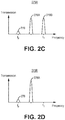
- Figure 2C illustrates one embodiment of a pump signal, a first order Stokes signal, and a second order Stokes signal in an optical ring resonator 275A.
- the pump signal 276 has a sufficiently high power to create the first order Stokes signal 278A, and the second order Stokes signal 278B in the optical ring resonator 150.
- the second order Stokes signal 268B is generated when the power level of the pump signal is four times the power level of the pump signal that initially generates the first order Stokes signal 268A.
- Figure 2D illustrates one embodiment of a pump signal and a first order Stokes signal in an optical ring resonator with an integrated Bragg grating 275B.
- the integrated Bragg grating of the optical resonator is designed to have a center frequency, or a Bragg frequency, that is substantially equal to the frequency of the second order Stokes signal, or f B ⁇ 3 ⁇ f R .
- the pump signal 276 has a sufficiently high power to create the first order Stokes signal 278A and the second order Stokes signal 278B in the optical ring resonator with the integrated Bragg grating 150, the second order Stokes signal 278B is suppressed because of two split resonances f R3 - ⁇ f271a and f R3 + ⁇ f R 271b created by the Bragg grating are sufficiently far from the 3dB band of the Brillouin gain for the second order Stokes signal.
- the power level of the first order Stokes signal can be increased higher than if the second order Stokes signal was not suppressed.
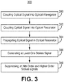
- Figure 3 illustrates one embodiment of a method of operation of an optical ring resonator with an integrated Bragg grating 300.
- FIG 3 illustrates one embodiment of a method of operation of an optical ring resonator with an integrated Bragg grating 300.
- the blocks of the flow diagrams have been arranged in a generally sequential manner for ease of explanation; however, it is to be understood that this arrangement is merely exemplary, and it should be recognized that the processing associated with the methods (and the blocks shown in the Figure) can occur in a different order (for example, where at least some of the processing associated with the blocks is performed in parallel and/or in an event-driven manner).
- block 380 couple an optical signal into an optical waveguide.
- block 382 couple an optical signal into an optical resonator, e.g. with a Bragg grating.
- block 384 propagate the optical signal around the optical resonator, e.g. with the Bragg grating.
- block 386 generate at least one Stokes signal having order(s) equal to or less than N-1. In another embodiment, N equals two, and generate a first order Stokes signal.
- suppress Nth order and higher order Stokes signals in the optical resonator e.g. with a Bragg grating.
- suppress the Nth order and higher order Stokes signals by generating a back reflected signal arising from signals, e.g. reflected by the Bragg grating, being in phase and adding constructively; the back reflected signal is at a center frequency (e.g. Bragg frequency), in the optical resonator (e.g. with the Bragg grating), that is substantially similar to the center frequency of a band of Brillouin gain corresponding to an Nth order Stokes signal.
- suppress second and higher order Stokes signals suppress second and higher order Stokes signals.
- the optical ring resonator with the integrated Bragg grating 150 can be used in a stimulated Brillouin scattering (SBS) ring laser gyroscope to eliminate higher order Stokes signals, e.g. second order and higher order Stokes signals.
- SBS ring laser gyroscopes are desirable because Stokes frequencies have low phase noise, and thus the SBS ring laser can accurately determine rotation around its input axis.
- the power level of the Stokes frequency can be increased so as to also increase the signal to noise ratio and thus the sensitivity of the SBS ring laser gyroscope.
- FIG. 4A illustrates one embodiment of a SBS ring single laser gyroscope including an optical ring resonator with the integrated Bragg grating 400A.
- the SBS ring single laser gyroscope including an optical ring resonator with the integrated Bragg grating 400A includes an optical ring resonator with the integrated Bragg grating 450, and is used to measure angular rotation ( ⁇ ) 411 around an input axis 430 of the optical ring resonator with the integrated Bragg grating 450.
- the SBS ring single laser gyroscope including an optical ring resonator with the integrated Bragg grating 400A illustrated in Figure 4 is one example of how to construct such a gyroscope. As is further illustrated below, other combinations of optical components may be used to implement the SBS ring single laser gyroscope including an optical ring resonator with the integrated Bragg grating.
- the SBS ring single laser gyroscope including an optical ring resonator with the integrated Bragg grating 400A includes a first laser 404.
- the first laser 404 includes a first input that is coupled to a first output of a resonance tracking servo system 410.
- the first laser 404 has a second input configured to be coupled to an output of a processing system 425.
- the processing system 425 is also configured to be coupled to and to control the power level of the first laser 404.
- An output of the first laser 404 is coupled to a first port of a first optical coupler (C1) 414.
- the resonance tracking servo system 110 includes PDH feedback control electronics, a subtractor, and an integrator as is illustrated in U.S. Patent No. 9,537,283 .
- the resonance tracking servo system 110 is respectively part of a Pound-Drever-Hall servo loop which is subsequently described in more detail.
- the processing system 425 includes a processor coupled to a memory.
- the processor may be implemented, in whole or in part, with a state machine or a field programmable gate array.
- the memory includes software, executed on the processor, to determine a parameter corresponding to the angular rotation rate ( ⁇ ) 411 around an input axis 430 of the optical ring resonator with the integrated Bragg grating 450.
- a second port of the first optical coupler 414 is coupled to a first input of a first phase modulator ( ⁇ Mod1) 416.
- a third port of the first optical coupler 414 is coupled to a first port of a second coupler (C2) 418.
- a first oscillator (Osc. 1) 415 is coupled to a second input of the first phase modulator 416.
- the first oscillator 415 is coupled to, and its frequency is controlled by, the resonance tracking servo system 410.
- the first oscillator 415 is a signal generator configured to generate a sinusoidal signal at a single frequency, e.g. within a range of one kHz and five GHz.
- the first oscillator 415, the first phase modulator 416, a third photodetector (PD3) 422, and the resonance tracking servo system 410 comprise a Pound-Drever-Hall servo loop.
- An output of the first phase modulator 416 is coupled to a first port of a first optical circulator (Cir1) 408.
- a second port and a third port of the first optical circulator 408 are respectively coupled to a first port of a resonator optical coupler (C0) 406 and a second port of the second optical coupler 418.
- the first circulator 408 directs light from the first port to the second port of the first circulator 408, so that light generated from the first laser 404 is injected to the optical resonator 402 in a counter-clockwise direction.
- a third port and a fourth port of the resonator optical coupler 406 are respectively coupled to a first port and a second port of the optical resonator with the integrated Bragg grating 450.
- the first order Stokes signal generated in the optical ring resonator with the integrated Bragg grating 450 by the pump signal from the first laser 404, propagates in the clockwise direction of the optical ring resonator with the integrated Bragg grating 450.
- This first order Stokes signal is coupled out of the optical ring resonator with the integrated Bragg grating 450 at the first port of the resonator optical coupler 406 and propagates from the second port of the first circulator 408 to its third port, and is coupled to the second port of the second optical coupler 418, and then to an input of a first photodetector (PD1) 413 (e.g. the second and third ports of the second optical coupler 418 combines the pump signal from the first laser 404 with the corresponding first order Stokes signal).
- a second port of the resonator optical coupler 406 is coupled to the third photodetector 422.
- a third port and a fourth port of the resonator optical coupler 406 are respectively coupled to a first port and a second port of an optical ring resonator with the integrated Bragg grating 450.
- the optical ring resonator with the integrated Bragg grating 450 is a coil of optical fiber (coil).
- different waveguides e.g. made from silicon nitride for example by semiconductor processing techniques, and different geometries, e.g. triangular, can be used.
- the output of the third photodetector 422 is coupled to an input of the resonance tracking servo system 410.
- the output of the first photodetector 413 is respectively coupled to an input of a first analog to digital converter 424.
- An output of the first analog to digital converter 424 is coupled to the processing system 425.
- a heater 428 is thermally coupled to the optical ring resonator with the integrated Bragg grating 450.
- the heater 428 is coupled to the processing system 425 which can activate and deactivate the heater 428, and adjust the temperature of the heater 128.
- the heater 428 is used to heat the optical ring resonator with the integrated Bragg grating 450, and thus adjust the resonant frequency of the optical ring resonator with the integrated Bragg grating, e.g. so that it is closer to the frequencies of the pump signals emitted by the first laser 404.
- the processing system 425 is configured to generate a signal, representative of the angular rotation rate ( ⁇ ) 411, around an input axis 430 of the optical ring resonator with the integrated Bragg grating 450.
- the input axis 430 is parallel to the center axis of the optical ring resonator with the integrated Bragg grating 450, e.g. the coil.
- the input axis 430 is a centerline through the optical ring resonator with the integrated Bragg grating 450, e.g. the coil.
- the input axis 430 need not be the centerline through the optical ring resonator with the integrated Bragg grating 450, e.g. the coil.
- the first laser 404 generates a first laser pump signal.
- the first laser pump signal 472 propagates counter-clockwise in the optical ring resonator with the integrated Bragg grating 450. If the power level of the first laser pump signal 472 is sufficiently high, a set of one or more Stokes signals is generated for the pump signal.
- a first laser first order Stokes signal 474 is generated from the first laser pump signal 472.
- the first laser first order Stokes signal 474 propagates clockwise (opposite the pump signal).
- a first beat signal, f B1 is generated by the first photodetector 413A as a result of the first laser first order Stokes signal 474 and the first laser pump signal 472A being incident on the first photodetector 413.
- the first laser pump signal 472 is incident upon the third photodetector 422, which generates an electrical signal corresponding to the power level of the first laser pump signal 472. This electrical signal is used to adjust the frequency of the first laser pump signal 472 so that it tracks a resonant frequency of the optical ring resonator with the integrated Bragg grating 450.
- the second and higher order Stokes signals that would be generated by the first laser first order Stokes signal 474. In another embodiment, this can be done by regulating the power level of the first laser pump signal 472 so that it is lower, e.g. than four times the power level that gives rise to first Stoke signal.
- lower power pump signals result in lower power first order Stokes signals.
- higher power levels of the first Stoke signals are desirable to increase the signal to noise levels, and thus the sensitivity, of the SBS ring laser gyroscope including an optical ring resonator with the integrated Bragg grating 300.
- second and higher order Stokes signals are suppressed by the optical ring resonator with the integrated Bragg grating 450 rather than by limiting the power level of the first laser pump signal 472.
- the power level of the first laser pump signal 472 can be increased to increase the power level of the first order Stokes signals.
- FIG. 4B illustrates one embodiment of a SBS ring dual laser gyroscope including an optical ring resonator with the integrated Bragg grating 400B.
- the SBS ring dual laser gyroscope including an optical ring resonator with the integrated Bragg grating 400B includes an optical ring resonator with the integrated Bragg grating 450, and is used to measure angular rotation ( ⁇ ) 411 around an input axis 430 of the optical ring resonator with the integrated Bragg grating 450.
- the SBS ring dual laser gyroscope including an optical ring resonator with the integrated Bragg grating 400B illustrated in Figure 4 is one example of how to construct such a gyroscope. As is further illustrated below, other combinations of optical components may be used to implement the SBS ring dual laser gyroscope including an optical ring resonator with the integrated Bragg grating.
- the SBS ring dual laser gyroscope including an optical ring resonator with the integrated Bragg grating 400B includes a first laser 404A and a second laser 404B.
- the first laser 404A includes a first input that is coupled to a first output of a resonance tracking servo system 410.
- the second laser 404B includes a first input that is coupled to a second output of a resonance tracking servo system 410.
- the first laser 404A and the second laser 404B each have a second input configured to be coupled to output(s) of a processing system 425.
- the processing system 425 is also configured to be coupled to and to control the power levels of the first laser 404A and the second laser 404B.
- the resonance tracking servo system 110 includes PDH feedback control electronics, a subtractor, and an integrator as is illustrated in U.S. Patent No. 9,537,283 .
- the resonance tracking servo system 110 is respectively part of a first Pound-Drever-Hall servo loop and a second Pound-Drever-Hall servo loop which are subsequently described in more detail.
- An output of the first laser 404A is coupled to a first port of a first optical coupler (C1) 414A.
- An output of the second laser 404B is coupled to a first port of a fourth optical coupler (C4) 414B.
- the processing system 425 includes a processor coupled to a memory.
- the processor may be implemented, in whole or in part, with a state machine or a field programmable gate array.
- the memory includes software, executed on the processor, to determine a parameter corresponding to the angular rotation rate ( ⁇ ) 411 around an input axis 430 of the optical ring resonator with the integrated Bragg grating 450.
- a second port of the first optical coupler 414A is coupled to a first input of a first phase modulator ( ⁇ Mod1) 416A.
- a third port of the first optical coupler 414A is coupled to a first port of a second coupler (C2) 418A.
- a second port of the fourth optical coupler 414B is coupled to a first input of a second phase modulator ( ⁇ Mod2) 416B.
- a third port of the fourth optical coupler 414B is coupled to a first port of a fifth coupler (C5) 418B.
- a first oscillator (Osc. 1) 415A is coupled to a second input of the first phase modulator 416A.
- a second oscillator (Osc. 2) 415B is coupled to a second input of the second phase modulator 116B.
- the first oscillator 415A and the second oscillator 415B are coupled to, and their frequencies are controlled by, the resonance tracking servo system 110.
- each of the first oscillator 415A and the second oscillator 415B are signal generators configured to generate sinusoidal signals at a single frequency, e.g. within a range of one kHz and five GHz.
- the first oscillator 415A, the first phase modulator 416A, the sixth optical coupler (C6) 420B, a fourth photodetector (PD4) 422B, and the resonance tracking servo system 410 comprise the first Pound-Drever-Hall servo loop;
- the second oscillator 415B, the second phase modulator 416B, the third coupler (C3) 420A, the third photodetector (PD3) 422A, and the resonance tracking servo system 410 comprise the second Pound-Drever-Hall servo loop.
- An output of the first phase modulator 416A is coupled to a first port of a first optical circulator (Cir1) 408A.
- An output of the second phase modulator 416B is coupled to a first port of a second optical circulator (Cir2) 408B.
- a second port and a third port of the first optical circulator 408A are respectively coupled to a first port of a resonator optical coupler (C0) 406 and a first port of a third optical coupler 420A.
- the first circulator 408A directs light from the first port to the second port of the first circulator 408A, so that light generated from the first laser 404A is injected to the optical resonator 402 in a counter-clockwise direction.
- a second port and a third port of the second optical circulator 408B are respectively coupled to a second port of the resonator optical coupler 406 and a first port of a sixth optical coupler 420B.
- the second circulator 408B directs light from the first port to the second port of the second circulator 408B, so that light generated from the second laser 404B is injected to the optical ring resonator with the integrated Bragg grating 450 in a clockwise direction.
- a third port and a fourth port of the resonator optical coupler 406 are respectively coupled to a first port and a second port of the optical resonator with the integrated Bragg grating 450.
- the first order Stokes signal generated in the optical ring resonator with the integrated Bragg grating 450 by the pump signal from the first laser 404A, propagates in the clockwise direction of the optical ring resonator with the integrated Bragg grating 450.
- This first order Stokes signal is coupled out of the optical ring resonator with the integrated Bragg grating 450 at the first port of the resonator optical coupler 406 and propagates from the second port of the first circulator 408A to its third port, and is coupled to the first port of the third optical coupler 420A.
- a second port and a third port of the third optical coupler 420A are respectively coupled to an input of a first photodetector (PD1) 413A ( e.g . through second and third ports of the second optical coupler 418A which combines the pump signal from the first laser 404A with the corresponding first order Stokes signal), and an input of a third photodetector 422A.
- PD1 photode
- the first order Stokes signal generated in the optical ring resonator with the integrated Bragg grating 450 by the pump signal from the second laser 404B, propagates in the counter-clockwise direction of the optical ring resonator with the integrated Bragg grating 450.
- This first order Stokes signal is coupled out of the optical ring resonator with the integrated Bragg grating 450 at the second port of the resonator optical coupler 406, and propagates from the second port of the second circulator 408B to the third port, and is coupled to the first port of the sixth optical coupler 420B.
- a second port and a third port of the sixth optical coupler 420B are respectively coupled to an input of a second photodetector (PD2) 413B ( e.g . through second and third ports of the fifth optical coupler 418B which combines the pump signal from the second laser 404B with the corresponding first order Stokes signal), and an input of a fourth photodetector 422B.
- PD2 photodetector
- a third port and a fourth port of the resonator optical coupler 406 are respectively coupled to a first port and a second port of an optical ring resonator with the integrated Bragg grating 450.
- the optical ring resonator with the integrated Bragg grating 450 is a coil of optical fiber (coil).
- different waveguides e.g. made from silicon nitride for example by semiconductor processing techniques, and different geometries, e.g. triangular, can be used.
- the outputs of the third photodetector 422A and the fourth photodetector 422B are respectively coupled to a first input and a second input of the resonance tracking servo system 410.
- the outputs of the first photodetector 413A and the second photodetector 413B are respectively coupled to inputs of a first analog to digital converter 424A and a second analog to digital converter 424B.
- Outputs of the first analog to digital converter 424A and the second analog to digital converter 424B are coupled to the processing system 425.
- a heater 428 is thermally coupled to the optical ring resonator with the integrated Bragg grating 450.
- the heater 428 is coupled to the processing system 425 which can activate and deactivate the heater 428, and adjust the temperature of the heater 128.
- the heater 428 is used to heat the optical ring resonator with the integrated Bragg grating 450, and thus adjust the resonant frequency of the optical ring resonator with the integrated Bragg grating, e.g. so that it is closer to the frequencies of the pump signals emitted by the first laser 404A and the second laser 404B.
- the processing system 425 is configured to generate a signal, representative of the angular rotation rate ( ⁇ ) 411, around an input axis 430 of the optical ring resonator with the integrated Bragg grating 450.
- the input axis 430 is parallel to the center axis of the optical ring resonator with the integrated Bragg grating 450, e.g. the coil.
- the input axis 430 is a centerline through the optical ring resonator with the integrated Bragg grating 450, e.g. the coil.
- the input axis 430 need not be the centerline through the optical ring resonator with the integrated Bragg grating 450, e.g. the coil.
- the first laser 404A and the second laser 404B respectively generate a first laser pump signal 472A and a second laser pump signal 472B.
- the first laser pump signal 472A and the second laser pump signal 472B respectively propagate counter-clockwise and clockwise in the optical ring resonator with the integrated Bragg grating 450. If the power levels of the first laser pump signal 472A and the second laser pump signal 472B are sufficiently high, a set of one or more Stokes signals is respectively generated for each pump signal.
- a first laser first order Stokes signal 474A and a second laser first order Stokes signal 474B are respectively generated from the first laser pump signal 472A and the second laser pump signal 472B.
- the first laser first order Stokes signal 474A and the second laser first order Stokes signal 474B propagate clockwise and counter-clockwise (opposite the corresponding pump signals).
- a first beat signal, f B1 is generated by the first photodetector 413A as a result of the first laser first order Stokes signal 474A and the first laser pump signal 472A being incident on the first photodetector 413A.
- a second beat signal, f B2 is generated by the second photodetector 413B as a result of the second laser first order Stokes signal 474B and the second laser pump signal 472B being incident upon the second photodetector 413B.
- ⁇ f R is equal to (f B1 - f B2 ) /2.
- the first laser pump signal 472A is incident upon the fourth photodetector 422B, which generates an electrical signal corresponding to the power level of the first laser pump signal 472A. This electrical signal is used to adjust the frequency of the first laser pump signal 472A so that it tracks a resonant frequency of the optical ring resonator with the integrated Bragg grating 450.
- the second laser pump signal 472B is incident upon the third photodetector 422A, which generates an electrical signal corresponding to the power level of the second laser pump signal 472B. This electrical signal is used to adjust the frequency of the second laser pump signal 472B so that it tracks a resonant frequency of the optical ring resonator with the integrated Bragg grating 450.
- second and higher order Stokes signals are suppressed by the optical ring resonator with the integrated Bragg grating 450 rather than by limiting the power levels of the first laser pump signal 472A and the second laser pump signal 372B.
- the power levels of the first laser pump signal 472A and the second laser pump signal 372B can be increased to increase the power levels of the corresponding first order Stokes signals.
- Figures 4A and 4B illustrate examples of combinations of optical couplers and/or circulators that can be used implement an SBS ring laser gyroscope.
- the SBS ring laser gyroscope can be implemented without the use of optical circulators.
- a second optical resonator optical coupler can be coupled to the side of the optical resonator with a Bragg grating 450 opposite the resonator optical coupler 406, in lieu of the optical circulators.
- the second resonator optical coupler would also be coupled to the third optical coupler 420A and the sixth optical coupler 420B to provide output signals, Stokes and laser pump signals, to the first photodetector 413A, the second photodetector 313B, the third photodetector 422A, and the fourth photodetector 422B.
- Terms of relative position as used in this application are defined based on a plane parallel to, or in the case of the term coplanar - the same plane as, the conventional plane or working surface of a layer, wafer, or substrate, regardless of orientation.
- the term “horizontal” or “lateral” as used in this application are defined as a plane parallel to the conventional plane or working surface of a layer, wafer, or substrate, regardless of orientation.
- the term “vertical” refers to a direction perpendicular to the horizontal. Terms such as “on,” “side” (as in “sidewall"), “higher,” “lower,” “over,” “top,” and “under” are defined with respect to the conventional plane or working surface being on the top surface of a layer, wafer, or substrate, regardless of orientation.
- the term “coplanar” as used in this application is defined as a plane in the same plane as the conventional plane or working surface of a layer, wafer, or substrate, regardless of orientation.
Landscapes
- Physics & Mathematics (AREA)
- Electromagnetism (AREA)
- Engineering & Computer Science (AREA)
- Optics & Photonics (AREA)
- Plasma & Fusion (AREA)
- Power Engineering (AREA)
- General Physics & Mathematics (AREA)
- Radar, Positioning & Navigation (AREA)
- Remote Sensing (AREA)
- Automation & Control Theory (AREA)
- Lasers (AREA)
- Gyroscopes (AREA)
Claims (9)
- Vorrichtung (150), umfassend:einen optischen Resonator, umfassend einen Wellenleiter, einschließlich Brillouin-Verstärkungsmaterial, auf einem Substrat;wobei der optische Resonator so konfiguriert ist, dass ein optisches Signal in ihn eingekoppelt werden kann;wobei der optische Resonator Resonanzfrequenzen aufweist, die im Wesentlichen gleich einer Frequenz eines in den optischen Resonator eingekoppelten optischen Signals und Frequenzen von mindestens zwei Stokes-Signalen sind;wobei ein Bragg-Gitter mit periodischen Kerben gebildet ist, die auf parallelen Seiten des Wellenleiters hergestellt sind, wobei die parallelen Seiten senkrecht zum Substrat sind; undwobei das Bragg-Gitter eine Bragg-Frequenz (167) aufweist, die im Wesentlichen gleich der Mittenfrequenz eines Stokes-Signals N-ter Ordnung ist, das durch das Brillouin-Verstärkungsmaterial erzeugt wird.
- Vorrichtung nach Anspruch 1, ferner umfassend einen Koppler (152) in der Nähe des optischen Resonators.
- Vorrichtung nach Anspruch 1, wobei die periodischen Kerben Kerben mit einem viereckigen Querschnitt aufweisen.
- Optischer Resonator nach Anspruch 1, wobei der optische Resonator ein optischer Ringresonator ist.
- Optischer Resonator nach Anspruch 1, wobei das N-te Stokes-Signal das Stokes-Signal zweiter Ordnung ist.
- Verfahren, umfassend:Einkoppeln eines optischen Signals in einen optischen Resonator (382), umfassend einen Wellenleiter, einschließlich Brillouin-Verstärkungsmaterial, auf einem Substrat;wobei der optische Resonator so konfiguriert ist, dass das optische Signal in ihn eingekoppelt werden kann;wobei der optische Resonator Resonanzfrequenzen aufweist, die im Wesentlichen gleich einer Frequenz des optischen Signals und einer Frequenz von mindestens zwei Stokes-Signalen sind;wobei ein Bragg-Gitter mit periodischen Kerben gebildet wird, die auf parallelen Seiten des Wellenleiters hergestellt sind, wobei die parallelen Seiten senkrecht zum Substrat sind;das optische Signal im optischen Resonator (384) ausbreiten;Erzeugen mindestens eines Stokes-Signals mit (einer) Ordnung(en) gleich oder kleiner als N-1 (386); undUnterdrücken von Stokes-Signalen N-ter Ordnung und höherer Ordnung im optischen Resonator (388).
- Verfahren nach Anspruch 6, ferner umfassend das Einkoppeln des optischen Signals in einen optischen Wellenleiter (380); und
wobei das Einkoppeln des optischen Signals in den optischen Resonatorabschnitt (382) das Einkoppeln des optischen Signals vom optischen Wellenleiter in den optischen Resonator umfasst. - Verfahren nach Anspruch 6, wobei das Einkoppeln des optischen Signals in den optischen Resonator (380) das Einkoppeln des optischen Signals in einen optischen Ringresonator umfasst;
wobei das Ausbreiten des optischen Signals im optischen Resonator (384) das Ausbreiten des optischen Signals im optischen Ringresonator umfasst; und
wobei das Unterdrücken der Stokes-Signale N-ter Ordnung und höherer Ordnung im optischen Resonator (388) das Unterdrücken der Stokes-Signale N-ter Ordnung und höherer Ordnung in einem optischen Ringresonator umfasst. - Verfahren nach Anspruch 6, wobei das Unterdrücken der Stokes-Signale N-ter Ordnung und höherer Ordnung im optischen Resonator (388) das Erzeugen eines zurückreflektierten Signals umfasst, das aus Signalen entsteht, die durch ein Bragg-Gitter auf dem optischen Resonator reflektiert werden, in Phase sind und sich konstruktiv addieren.
Applications Claiming Priority (1)
| Application Number | Priority Date | Filing Date | Title |
|---|---|---|---|
| US15/618,833 US10992097B2 (en) | 2017-06-09 | 2017-06-09 | Apparatus and method for an optical resonator with an integrated Bragg grating |
Publications (2)
| Publication Number | Publication Date |
|---|---|
| EP3425751A1 EP3425751A1 (de) | 2019-01-09 |
| EP3425751B1 true EP3425751B1 (de) | 2021-06-16 |
Family
ID=61899089
Family Applications (1)
| Application Number | Title | Priority Date | Filing Date |
|---|---|---|---|
| EP18165567.1A Active EP3425751B1 (de) | 2017-06-09 | 2018-04-03 | Vorrichtung und verfahren für einen optischen resonator mit integriertem bragg-gitter |
Country Status (2)
| Country | Link |
|---|---|
| US (1) | US10992097B2 (de) |
| EP (1) | EP3425751B1 (de) |
Families Citing this family (8)
| Publication number | Priority date | Publication date | Assignee | Title |
|---|---|---|---|---|
| US11079233B2 (en) * | 2019-09-18 | 2021-08-03 | Honeywell International Inc. | Stimulated brillouin scattering gyroscope |
| US10907967B1 (en) | 2019-10-02 | 2021-02-02 | Honeywell International Inc. | Ring laser gyroscopes with active volume Bragg grating |
| US10855372B1 (en) | 2019-10-16 | 2020-12-01 | Honeywell International Inc. | Systems and methods for reduction of optical signal line width |
| US11486706B2 (en) * | 2020-04-24 | 2022-11-01 | Honeywell International Inc. | Kerr effect reduction in SBS laser gyroscope |
| CN112729271B (zh) * | 2020-12-21 | 2022-07-15 | 北京航空航天大学 | 一种基于奇异点谐振模式劈裂的光学陀螺谐振腔结构 |
| US11431144B2 (en) | 2021-01-06 | 2022-08-30 | Honeywell International Inc. | Suppression of higher-order lasing in a Brillouin laser using nested ring resonators |
| US11656080B1 (en) | 2022-08-23 | 2023-05-23 | Anello Photonics, Inc. | Silicon nitride waveguide based integrated photonics front-end chip for optical gyroscope |
| CN119780459B (zh) * | 2024-12-11 | 2025-10-17 | 北京科技大学 | 一种基于双硅基微环谐振解调的角速度传感方法及系统 |
Family Cites Families (51)
| Publication number | Priority date | Publication date | Assignee | Title |
|---|---|---|---|---|
| US3958188A (en) * | 1974-12-11 | 1976-05-18 | Nasa | Fiber distributed feedback laser |
| US4159178A (en) | 1976-11-24 | 1979-06-26 | University Of Utah Research Institute | Stimulated brillouin scattering ring laser gyroscope |
| US4396290A (en) | 1979-09-24 | 1983-08-02 | University Of Utah Research Institute | Two pump-frequency-stimulated Brillouin scattering ring laser gyroscope |
| US4922481A (en) | 1985-08-01 | 1990-05-01 | Hicks John W | Optical communication systems enabling minimal subscriber components |
| US4952059A (en) * | 1986-06-06 | 1990-08-28 | The Board Of Trustees Of The Leland Stanford Junior University | Reentrant fiber raman gyroscope |
| US4863272A (en) | 1988-05-12 | 1989-09-05 | The Charles Stark Draper Laboratory, Inc. | Multi-mode fiber optic resonator gyroscope |
| US5064288A (en) | 1990-12-07 | 1991-11-12 | The Charles Stark Draper Laboratory | Scattered light multi-Brillouin gyroscope |
| US5408317A (en) | 1990-12-28 | 1995-04-18 | The Charles Stark Draper Laboratory, Inc. | Scattered light moire-brillouin gyroscope |
| US5295209A (en) * | 1991-03-12 | 1994-03-15 | General Instrument Corporation | Spontaneous emission source having high spectral density at a desired wavelength |
| US5440669A (en) * | 1991-07-26 | 1995-08-08 | Accuwave Corporation | Photorefractive systems and methods |
| DE4218905A1 (de) | 1992-06-09 | 1993-12-16 | Bodenseewerk Geraetetech | Brillouin-Ringlaser |
| US5351252A (en) | 1993-02-26 | 1994-09-27 | The Board Of Trustees Of The Leland Stanford University | Technique of reducing the Kerr effect and extending the dynamic range in a Brillouin fiber optic gyroscope |
| US5406370A (en) | 1993-02-26 | 1995-04-11 | The Board Of Trustees Of The Leland Stanford University | Winding technique for decreasing the pump power requirement of a brillouin fiber optic gyroscope |
| US5323404A (en) * | 1993-11-02 | 1994-06-21 | At&T Bell Laboratories | Optical fiber laser or amplifier including high reflectivity gratings |
| DE4407348A1 (de) | 1994-03-05 | 1995-09-07 | Bodenseewerk Geraetetech | Brillouin-Ringlaserkreisel |
| US5537671A (en) | 1995-02-10 | 1996-07-16 | The Board Of Trustees Of The Leland Stanford Junior University | Technique of reducing the Kerr effect and extending the dynamic range in a brillouin fiber optic gyroscope |
| US5912910A (en) * | 1996-05-17 | 1999-06-15 | Sdl, Inc. | High power pumped mid-IR wavelength systems using nonlinear frequency mixing (NFM) devices |
| AUPO998997A0 (en) * | 1997-10-24 | 1997-11-20 | University Of Sydney, The | Brillouin/erbium fibre laser current monitor using elliptically polarizing fibre |
| JP3779054B2 (ja) * | 1998-01-23 | 2006-05-24 | 富士通株式会社 | 可変光学フィルタ |
| US6411429B1 (en) * | 1999-10-19 | 2002-06-25 | Fujitsu Limited | Optical amplifying apparatus, wide-band optical amplifying apparatus, and optical communication system |
| US6407855B1 (en) * | 1999-10-29 | 2002-06-18 | Sdl, Inc. | Multiple wavelength optical sources |
| US6424664B1 (en) | 2000-02-03 | 2002-07-23 | Electronics And Telecommunications Research Institute | Brillouin/erbuim fiber laser outputting dual spacing multiwavelength light |
| EP1241746A1 (de) * | 2001-03-14 | 2002-09-18 | Europäische Organisation für astronomische Forschung in der südlichen Hemisphäre | Schmalbandige Hochleistungsfaserlaser |
| US7065276B2 (en) | 2003-04-03 | 2006-06-20 | Lambda Crossing Ltd. | Integrated optical filters utilizing resonators |
| WO2005033749A2 (en) | 2003-10-01 | 2005-04-14 | California Institute Of Technology | Tunable resonator-based devices for producing variable delays and narrow spectral linewidths |
| US7272160B1 (en) * | 2005-01-24 | 2007-09-18 | Np Photonics, Inc | Single-frequency Brillouin fiber ring laser with extremely narrow linewidth |
| US7372574B2 (en) | 2005-12-09 | 2008-05-13 | Honeywell International Inc. | System and method for stabilizing light sources in resonator gyro |
| US7463360B2 (en) | 2006-04-18 | 2008-12-09 | Honeywell International Inc. | Optical resonator gyro with integrated external cavity beam generator |
| US7184624B1 (en) | 2006-06-05 | 2007-02-27 | The United States Of America As Represented By The Administrator Of The National Aeronautics And Space Administration | Vertically-coupled whispering gallery mode resonator optical waveguide, and methods |
| WO2009056365A1 (en) * | 2007-10-29 | 2009-05-07 | Telefonaktiebolaget Lm Ericsson (Publ) | Improvements in or relating to optical networks |
| JP4448199B2 (ja) * | 2008-02-29 | 2010-04-07 | 株式会社フジクラ | 基板型光導波路素子、波長分散補償素子、光フィルタならびに光共振器、およびそれらの設計方法 |
| US8102597B1 (en) | 2008-05-15 | 2012-01-24 | Oewaves, Inc. | Structures and fabrication of whispering-gallery-mode resonators |
| FR2934365B1 (fr) | 2008-07-25 | 2010-08-13 | Thales Sa | Capteur a fibre optique auto-reference a diffusion brillouin stimulee |
| US8718112B2 (en) | 2008-10-10 | 2014-05-06 | International Business Machines Corporation | Radial Bragg ring resonator structure with high quality factor |
| US20110134940A1 (en) * | 2009-12-08 | 2011-06-09 | Schlumberger Technology Corporation | Narrow linewidth brillouin laser |
| WO2011119232A2 (en) | 2010-03-23 | 2011-09-29 | Oewaves, Inc. | Optical gyroscope sensors based on optical whispering gallery mode resonators |
| US20120189025A1 (en) | 2010-11-23 | 2012-07-26 | Oracle International Corporation | Monolithic laser source using ring-resonator reflectors |
| US8472486B1 (en) * | 2011-08-17 | 2013-06-25 | The United States Of America As Represented By The Secretary Of The Air Force | Seeded raman amplifier for applications in the 1100-1500 nm spectral region |
| US9083147B2 (en) * | 2011-10-28 | 2015-07-14 | Ofs Fitel, Llc | Distributed feedback (DFB) Brillouin fiber lasers |
| US8659760B2 (en) | 2012-04-12 | 2014-02-25 | Honeywell International Inc. | Resonator fiber optic gyroscope utilizing laser frequency combs |
| US9252559B2 (en) | 2012-07-10 | 2016-02-02 | Honeywell International Inc. | Narrow bandwidth reflectors for reducing stimulated Brillouin scattering in optical cavities |
| US8923352B2 (en) | 2012-08-10 | 2014-12-30 | Honeywell International Inc. | Laser with transmission and reflection mode feedback control |
| US8830478B2 (en) | 2012-12-04 | 2014-09-09 | Honeywell International Inc. | Optical frequency comb stimulated Brillouin scattering gyroscope |
| US9581448B2 (en) * | 2013-04-27 | 2017-02-28 | Magiq Technologies, Inc. | Optical sensors using stimulated brillouin scattering |
| WO2015191124A2 (en) | 2014-03-06 | 2015-12-17 | California Institute Of Technology | Stable microwave-frequency source based on cascaded brillouin lasers |
| US9197032B2 (en) | 2014-04-02 | 2015-11-24 | Honeywell International Inc. | Systems and methods for stabilized stimulated brillouin scattering lasers with ultra-low phase noise |
| US9594267B2 (en) * | 2014-10-16 | 2017-03-14 | The Board Of Trustees Of The University Of Illinois | System and method for brillouin scattering induced transparency |
| US20160204571A1 (en) * | 2015-01-14 | 2016-07-14 | Honeywell International Inc. | Systems and methods for an optical frequency comb stimulated brillouin scattering gyroscope with rigid optical waveguide resonator |
| US9733084B2 (en) | 2015-09-09 | 2017-08-15 | Honeywell International Inc. | Single pump cascaded stimulated Brillouin scattering (SBS) ring laser gyro |
| US20180081205A1 (en) * | 2016-09-20 | 2018-03-22 | Honeywell International Inc. | Double-layer high-confinement acousto-optic waveguide |
| US10429677B2 (en) * | 2016-09-20 | 2019-10-01 | Honeywell International Inc. | Optical waveguide having a wide brillouin bandwidth |
-
2017
- 2017-06-09 US US15/618,833 patent/US10992097B2/en active Active
-
2018
- 2018-04-03 EP EP18165567.1A patent/EP3425751B1/de active Active
Also Published As
| Publication number | Publication date |
|---|---|
| US10992097B2 (en) | 2021-04-27 |
| US20180358772A1 (en) | 2018-12-13 |
| EP3425751A1 (de) | 2019-01-09 |
Similar Documents
| Publication | Publication Date | Title |
|---|---|---|
| EP3425751A1 (de) | Vorrichtung und verfahren für einen optischen resonator mit integriertem bragg-gitter | |
| US9519115B2 (en) | Optical circuit | |
| EP3141865B1 (de) | Kaskadierter stimulierter einzelpumpen-brillouin-streuungsringlaserkreisel | |
| US9130350B2 (en) | Laser device that includes ring resonator | |
| CA1301510C (en) | Apparatus and method for optical signal source stabilization | |
| Ciminelli et al. | A high-Q InP resonant angular velocity sensor for a monolithically integrated optical gyroscope | |
| JP5290737B2 (ja) | 光−マイクロ波発振器及びパルス発生装置 | |
| CN114829876A (zh) | 用于集成光子光学陀螺仪的系统架构 | |
| US7903255B2 (en) | Sagnac sensor with nested waveguides | |
| US20170241784A1 (en) | Stimulated brillouin scattering (sbs) gyro with coupled resonator for frequency-dependent output coupling | |
| EP3528019A1 (de) | Metallischer blender zwischen lichtwellenleitern zur reduzierung von übersprechen | |
| US20110064360A1 (en) | Optical semiconductor element and method for manufacturing the same | |
| EP3771888B1 (de) | Umschalten eines sbs-kreisels mit fester pumpentrennung | |
| JP2019192902A (ja) | アルカリ分光法のための装置及び方法 | |
| WO2020145173A1 (ja) | 波長可変レーザ | |
| US4533249A (en) | Passive ring resonator angular rate sensor | |
| US10855372B1 (en) | Systems and methods for reduction of optical signal line width | |
| EP3647724A1 (de) | Durch drei pumpen stimulierter brillouin-streuungskreisel | |
| US20240271936A1 (en) | Transverse magnetic mode travelling wave resonator with at least one bragg grating and gyroscope applications thereof | |
| JP4208126B2 (ja) | ゲインクランプ光増幅器モジュール | |
| JP4107426B2 (ja) | ゲインクランプ光増幅器 | |
| US20240369776A1 (en) | Travelling wave resonator with at least two cores | |
| JPS6135486B2 (de) | ||
| JP2013156288A (ja) | 光半導体装置 | |
| Armenise et al. | Out-of-resonance measurement scheme for ring resonator gyroscopes |
Legal Events
| Date | Code | Title | Description |
|---|---|---|---|
| PUAI | Public reference made under article 153(3) epc to a published international application that has entered the european phase |
Free format text: ORIGINAL CODE: 0009012 |
|
| STAA | Information on the status of an ep patent application or granted ep patent |
Free format text: STATUS: REQUEST FOR EXAMINATION WAS MADE |
|
| 17P | Request for examination filed |
Effective date: 20180403 |
|
| AK | Designated contracting states |
Kind code of ref document: A1 Designated state(s): AL AT BE BG CH CY CZ DE DK EE ES FI FR GB GR HR HU IE IS IT LI LT LU LV MC MK MT NL NO PL PT RO RS SE SI SK SM TR |
|
| AX | Request for extension of the european patent |
Extension state: BA ME |
|
| GRAP | Despatch of communication of intention to grant a patent |
Free format text: ORIGINAL CODE: EPIDOSNIGR1 |
|
| STAA | Information on the status of an ep patent application or granted ep patent |
Free format text: STATUS: GRANT OF PATENT IS INTENDED |
|
| INTG | Intention to grant announced |
Effective date: 20210223 |
|
| GRAS | Grant fee paid |
Free format text: ORIGINAL CODE: EPIDOSNIGR3 |
|
| GRAA | (expected) grant |
Free format text: ORIGINAL CODE: 0009210 |
|
| STAA | Information on the status of an ep patent application or granted ep patent |
Free format text: STATUS: THE PATENT HAS BEEN GRANTED |
|
| AK | Designated contracting states |
Kind code of ref document: B1 Designated state(s): AL AT BE BG CH CY CZ DE DK EE ES FI FR GB GR HR HU IE IS IT LI LT LU LV MC MK MT NL NO PL PT RO RS SE SI SK SM TR |
|
| REG | Reference to a national code |
Ref country code: GB Ref legal event code: FG4D |
|
| REG | Reference to a national code |
Ref country code: CH Ref legal event code: EP |
|
| REG | Reference to a national code |
Ref country code: DE Ref legal event code: R096 Ref document number: 602018018534 Country of ref document: DE |
|
| REG | Reference to a national code |
Ref country code: AT Ref legal event code: REF Ref document number: 1403119 Country of ref document: AT Kind code of ref document: T Effective date: 20210715 |
|
| REG | Reference to a national code |
Ref country code: IE Ref legal event code: FG4D |
|
| REG | Reference to a national code |
Ref country code: LT Ref legal event code: MG9D |
|
| PG25 | Lapsed in a contracting state [announced via postgrant information from national office to epo] |
Ref country code: FI Free format text: LAPSE BECAUSE OF FAILURE TO SUBMIT A TRANSLATION OF THE DESCRIPTION OR TO PAY THE FEE WITHIN THE PRESCRIBED TIME-LIMIT Effective date: 20210616 Ref country code: HR Free format text: LAPSE BECAUSE OF FAILURE TO SUBMIT A TRANSLATION OF THE DESCRIPTION OR TO PAY THE FEE WITHIN THE PRESCRIBED TIME-LIMIT Effective date: 20210616 Ref country code: LT Free format text: LAPSE BECAUSE OF FAILURE TO SUBMIT A TRANSLATION OF THE DESCRIPTION OR TO PAY THE FEE WITHIN THE PRESCRIBED TIME-LIMIT Effective date: 20210616 Ref country code: BG Free format text: LAPSE BECAUSE OF FAILURE TO SUBMIT A TRANSLATION OF THE DESCRIPTION OR TO PAY THE FEE WITHIN THE PRESCRIBED TIME-LIMIT Effective date: 20210916 |
|
| REG | Reference to a national code |
Ref country code: AT Ref legal event code: MK05 Ref document number: 1403119 Country of ref document: AT Kind code of ref document: T Effective date: 20210616 |
|
| REG | Reference to a national code |
Ref country code: NL Ref legal event code: MP Effective date: 20210616 |
|
| PG25 | Lapsed in a contracting state [announced via postgrant information from national office to epo] |
Ref country code: RS Free format text: LAPSE BECAUSE OF FAILURE TO SUBMIT A TRANSLATION OF THE DESCRIPTION OR TO PAY THE FEE WITHIN THE PRESCRIBED TIME-LIMIT Effective date: 20210616 Ref country code: SE Free format text: LAPSE BECAUSE OF FAILURE TO SUBMIT A TRANSLATION OF THE DESCRIPTION OR TO PAY THE FEE WITHIN THE PRESCRIBED TIME-LIMIT Effective date: 20210616 Ref country code: LV Free format text: LAPSE BECAUSE OF FAILURE TO SUBMIT A TRANSLATION OF THE DESCRIPTION OR TO PAY THE FEE WITHIN THE PRESCRIBED TIME-LIMIT Effective date: 20210616 Ref country code: NO Free format text: LAPSE BECAUSE OF FAILURE TO SUBMIT A TRANSLATION OF THE DESCRIPTION OR TO PAY THE FEE WITHIN THE PRESCRIBED TIME-LIMIT Effective date: 20210916 Ref country code: GR Free format text: LAPSE BECAUSE OF FAILURE TO SUBMIT A TRANSLATION OF THE DESCRIPTION OR TO PAY THE FEE WITHIN THE PRESCRIBED TIME-LIMIT Effective date: 20210917 |
|
| PG25 | Lapsed in a contracting state [announced via postgrant information from national office to epo] |
Ref country code: CZ Free format text: LAPSE BECAUSE OF FAILURE TO SUBMIT A TRANSLATION OF THE DESCRIPTION OR TO PAY THE FEE WITHIN THE PRESCRIBED TIME-LIMIT Effective date: 20210616 Ref country code: AT Free format text: LAPSE BECAUSE OF FAILURE TO SUBMIT A TRANSLATION OF THE DESCRIPTION OR TO PAY THE FEE WITHIN THE PRESCRIBED TIME-LIMIT Effective date: 20210616 Ref country code: RO Free format text: LAPSE BECAUSE OF FAILURE TO SUBMIT A TRANSLATION OF THE DESCRIPTION OR TO PAY THE FEE WITHIN THE PRESCRIBED TIME-LIMIT Effective date: 20210616 Ref country code: PT Free format text: LAPSE BECAUSE OF FAILURE TO SUBMIT A TRANSLATION OF THE DESCRIPTION OR TO PAY THE FEE WITHIN THE PRESCRIBED TIME-LIMIT Effective date: 20211018 Ref country code: NL Free format text: LAPSE BECAUSE OF FAILURE TO SUBMIT A TRANSLATION OF THE DESCRIPTION OR TO PAY THE FEE WITHIN THE PRESCRIBED TIME-LIMIT Effective date: 20210616 Ref country code: EE Free format text: LAPSE BECAUSE OF FAILURE TO SUBMIT A TRANSLATION OF THE DESCRIPTION OR TO PAY THE FEE WITHIN THE PRESCRIBED TIME-LIMIT Effective date: 20210616 Ref country code: ES Free format text: LAPSE BECAUSE OF FAILURE TO SUBMIT A TRANSLATION OF THE DESCRIPTION OR TO PAY THE FEE WITHIN THE PRESCRIBED TIME-LIMIT Effective date: 20210616 Ref country code: SM Free format text: LAPSE BECAUSE OF FAILURE TO SUBMIT A TRANSLATION OF THE DESCRIPTION OR TO PAY THE FEE WITHIN THE PRESCRIBED TIME-LIMIT Effective date: 20210616 Ref country code: SK Free format text: LAPSE BECAUSE OF FAILURE TO SUBMIT A TRANSLATION OF THE DESCRIPTION OR TO PAY THE FEE WITHIN THE PRESCRIBED TIME-LIMIT Effective date: 20210616 |
|
| PG25 | Lapsed in a contracting state [announced via postgrant information from national office to epo] |
Ref country code: PL Free format text: LAPSE BECAUSE OF FAILURE TO SUBMIT A TRANSLATION OF THE DESCRIPTION OR TO PAY THE FEE WITHIN THE PRESCRIBED TIME-LIMIT Effective date: 20210616 |
|
| REG | Reference to a national code |
Ref country code: DE Ref legal event code: R097 Ref document number: 602018018534 Country of ref document: DE |
|
| PLBE | No opposition filed within time limit |
Free format text: ORIGINAL CODE: 0009261 |
|
| STAA | Information on the status of an ep patent application or granted ep patent |
Free format text: STATUS: NO OPPOSITION FILED WITHIN TIME LIMIT |
|
| PG25 | Lapsed in a contracting state [announced via postgrant information from national office to epo] |
Ref country code: DK Free format text: LAPSE BECAUSE OF FAILURE TO SUBMIT A TRANSLATION OF THE DESCRIPTION OR TO PAY THE FEE WITHIN THE PRESCRIBED TIME-LIMIT Effective date: 20210616 |
|
| 26N | No opposition filed |
Effective date: 20220317 |
|
| PG25 | Lapsed in a contracting state [announced via postgrant information from national office to epo] |
Ref country code: AL Free format text: LAPSE BECAUSE OF FAILURE TO SUBMIT A TRANSLATION OF THE DESCRIPTION OR TO PAY THE FEE WITHIN THE PRESCRIBED TIME-LIMIT Effective date: 20210616 |
|
| PG25 | Lapsed in a contracting state [announced via postgrant information from national office to epo] |
Ref country code: IT Free format text: LAPSE BECAUSE OF FAILURE TO SUBMIT A TRANSLATION OF THE DESCRIPTION OR TO PAY THE FEE WITHIN THE PRESCRIBED TIME-LIMIT Effective date: 20210616 |
|
| REG | Reference to a national code |
Ref country code: DE Ref legal event code: R119 Ref document number: 602018018534 Country of ref document: DE |
|
| REG | Reference to a national code |
Ref country code: CH Ref legal event code: PL |
|
| GBPC | Gb: european patent ceased through non-payment of renewal fee |
Effective date: 20220403 |
|
| REG | Reference to a national code |
Ref country code: BE Ref legal event code: MM Effective date: 20220430 |
|
| PG25 | Lapsed in a contracting state [announced via postgrant information from national office to epo] |
Ref country code: MC Free format text: LAPSE BECAUSE OF FAILURE TO SUBMIT A TRANSLATION OF THE DESCRIPTION OR TO PAY THE FEE WITHIN THE PRESCRIBED TIME-LIMIT Effective date: 20210616 Ref country code: LU Free format text: LAPSE BECAUSE OF NON-PAYMENT OF DUE FEES Effective date: 20220403 Ref country code: LI Free format text: LAPSE BECAUSE OF NON-PAYMENT OF DUE FEES Effective date: 20220430 Ref country code: GB Free format text: LAPSE BECAUSE OF NON-PAYMENT OF DUE FEES Effective date: 20220403 Ref country code: DE Free format text: LAPSE BECAUSE OF NON-PAYMENT OF DUE FEES Effective date: 20221103 Ref country code: CH Free format text: LAPSE BECAUSE OF NON-PAYMENT OF DUE FEES Effective date: 20220430 |
|
| PG25 | Lapsed in a contracting state [announced via postgrant information from national office to epo] |
Ref country code: BE Free format text: LAPSE BECAUSE OF NON-PAYMENT OF DUE FEES Effective date: 20220430 |
|
| PG25 | Lapsed in a contracting state [announced via postgrant information from national office to epo] |
Ref country code: IE Free format text: LAPSE BECAUSE OF NON-PAYMENT OF DUE FEES Effective date: 20220403 |
|
| P01 | Opt-out of the competence of the unified patent court (upc) registered |
Effective date: 20230525 |
|
| PG25 | Lapsed in a contracting state [announced via postgrant information from national office to epo] |
Ref country code: HU Free format text: LAPSE BECAUSE OF FAILURE TO SUBMIT A TRANSLATION OF THE DESCRIPTION OR TO PAY THE FEE WITHIN THE PRESCRIBED TIME-LIMIT; INVALID AB INITIO Effective date: 20180403 |
|
| PG25 | Lapsed in a contracting state [announced via postgrant information from national office to epo] |
Ref country code: MK Free format text: LAPSE BECAUSE OF FAILURE TO SUBMIT A TRANSLATION OF THE DESCRIPTION OR TO PAY THE FEE WITHIN THE PRESCRIBED TIME-LIMIT Effective date: 20210616 Ref country code: CY Free format text: LAPSE BECAUSE OF FAILURE TO SUBMIT A TRANSLATION OF THE DESCRIPTION OR TO PAY THE FEE WITHIN THE PRESCRIBED TIME-LIMIT Effective date: 20210616 |
|
| PG25 | Lapsed in a contracting state [announced via postgrant information from national office to epo] |
Ref country code: MT Free format text: LAPSE BECAUSE OF FAILURE TO SUBMIT A TRANSLATION OF THE DESCRIPTION OR TO PAY THE FEE WITHIN THE PRESCRIBED TIME-LIMIT Effective date: 20210616 |
|
| PGFP | Annual fee paid to national office [announced via postgrant information from national office to epo] |
Ref country code: FR Payment date: 20250424 Year of fee payment: 8 |
|
| PG25 | Lapsed in a contracting state [announced via postgrant information from national office to epo] |
Ref country code: TR Free format text: LAPSE BECAUSE OF FAILURE TO SUBMIT A TRANSLATION OF THE DESCRIPTION OR TO PAY THE FEE WITHIN THE PRESCRIBED TIME-LIMIT Effective date: 20210616 |