EP3425354A1 - Spectrophotomètre hyperspectral large bande - Google Patents
Spectrophotomètre hyperspectral large bande Download PDFInfo
- Publication number
- EP3425354A1 EP3425354A1 EP18180891.6A EP18180891A EP3425354A1 EP 3425354 A1 EP3425354 A1 EP 3425354A1 EP 18180891 A EP18180891 A EP 18180891A EP 3425354 A1 EP3425354 A1 EP 3425354A1
- Authority
- EP
- European Patent Office
- Prior art keywords
- mirror
- slot
- imaging
- line
- spectrophotometer
- Prior art date
- Legal status (The legal status is an assumption and is not a legal conclusion. Google has not performed a legal analysis and makes no representation as to the accuracy of the status listed.)
- Granted
Links
Images



Classifications
-
- G—PHYSICS
- G02—OPTICS
- G02B—OPTICAL ELEMENTS, SYSTEMS OR APPARATUS
- G02B21/00—Microscopes
- G02B21/0004—Microscopes specially adapted for specific applications
- G02B21/002—Scanning microscopes
- G02B21/0024—Confocal scanning microscopes (CSOMs) or confocal "macroscopes"; Accessories which are not restricted to use with CSOMs, e.g. sample holders
- G02B21/0036—Scanning details, e.g. scanning stages
- G02B21/0048—Scanning details, e.g. scanning stages scanning mirrors, e.g. rotating or galvanomirrors, MEMS mirrors
-
- G—PHYSICS
- G01—MEASURING; TESTING
- G01J—MEASUREMENT OF INTENSITY, VELOCITY, SPECTRAL CONTENT, POLARISATION, PHASE OR PULSE CHARACTERISTICS OF INFRARED, VISIBLE OR ULTRAVIOLET LIGHT; COLORIMETRY; RADIATION PYROMETRY
- G01J3/00—Spectrometry; Spectrophotometry; Monochromators; Measuring colours
- G01J3/28—Investigating the spectrum
- G01J3/2823—Imaging spectrometer
-
- G—PHYSICS
- G01—MEASURING; TESTING
- G01J—MEASUREMENT OF INTENSITY, VELOCITY, SPECTRAL CONTENT, POLARISATION, PHASE OR PULSE CHARACTERISTICS OF INFRARED, VISIBLE OR ULTRAVIOLET LIGHT; COLORIMETRY; RADIATION PYROMETRY
- G01J3/00—Spectrometry; Spectrophotometry; Monochromators; Measuring colours
- G01J3/02—Details
- G01J3/0205—Optical elements not provided otherwise, e.g. optical manifolds, diffusers, windows
- G01J3/0208—Optical elements not provided otherwise, e.g. optical manifolds, diffusers, windows using focussing or collimating elements, e.g. lenses or mirrors; performing aberration correction
-
- G—PHYSICS
- G01—MEASURING; TESTING
- G01J—MEASUREMENT OF INTENSITY, VELOCITY, SPECTRAL CONTENT, POLARISATION, PHASE OR PULSE CHARACTERISTICS OF INFRARED, VISIBLE OR ULTRAVIOLET LIGHT; COLORIMETRY; RADIATION PYROMETRY
- G01J3/00—Spectrometry; Spectrophotometry; Monochromators; Measuring colours
- G01J3/02—Details
- G01J3/0205—Optical elements not provided otherwise, e.g. optical manifolds, diffusers, windows
- G01J3/021—Optical elements not provided otherwise, e.g. optical manifolds, diffusers, windows using plane or convex mirrors, parallel phase plates, or particular reflectors
-
- G—PHYSICS
- G01—MEASURING; TESTING
- G01J—MEASUREMENT OF INTENSITY, VELOCITY, SPECTRAL CONTENT, POLARISATION, PHASE OR PULSE CHARACTERISTICS OF INFRARED, VISIBLE OR ULTRAVIOLET LIGHT; COLORIMETRY; RADIATION PYROMETRY
- G01J3/00—Spectrometry; Spectrophotometry; Monochromators; Measuring colours
- G01J3/02—Details
- G01J3/0205—Optical elements not provided otherwise, e.g. optical manifolds, diffusers, windows
- G01J3/0243—Optical elements not provided otherwise, e.g. optical manifolds, diffusers, windows having a through-hole enabling the optical element to fulfil an additional optical function, e.g. a mirror or grating having a throughhole for a light collecting or light injecting optical fiber
-
- G—PHYSICS
- G01—MEASURING; TESTING
- G01J—MEASUREMENT OF INTENSITY, VELOCITY, SPECTRAL CONTENT, POLARISATION, PHASE OR PULSE CHARACTERISTICS OF INFRARED, VISIBLE OR ULTRAVIOLET LIGHT; COLORIMETRY; RADIATION PYROMETRY
- G01J3/00—Spectrometry; Spectrophotometry; Monochromators; Measuring colours
- G01J3/02—Details
- G01J3/0205—Optical elements not provided otherwise, e.g. optical manifolds, diffusers, windows
- G01J3/0254—Spectrometers, other than colorimeters, making use of an integrating sphere
-
- G—PHYSICS
- G01—MEASURING; TESTING
- G01J—MEASUREMENT OF INTENSITY, VELOCITY, SPECTRAL CONTENT, POLARISATION, PHASE OR PULSE CHARACTERISTICS OF INFRARED, VISIBLE OR ULTRAVIOLET LIGHT; COLORIMETRY; RADIATION PYROMETRY
- G01J3/00—Spectrometry; Spectrophotometry; Monochromators; Measuring colours
- G01J3/02—Details
- G01J3/0289—Field-of-view determination; Aiming or pointing of a spectrometer; Adjusting alignment; Encoding angular position; Size of measurement area; Position tracking
-
- G—PHYSICS
- G01—MEASURING; TESTING
- G01J—MEASUREMENT OF INTENSITY, VELOCITY, SPECTRAL CONTENT, POLARISATION, PHASE OR PULSE CHARACTERISTICS OF INFRARED, VISIBLE OR ULTRAVIOLET LIGHT; COLORIMETRY; RADIATION PYROMETRY
- G01J3/00—Spectrometry; Spectrophotometry; Monochromators; Measuring colours
- G01J3/12—Generating the spectrum; Monochromators
- G01J3/14—Generating the spectrum; Monochromators using refracting elements, e.g. prisms
-
- G—PHYSICS
- G01—MEASURING; TESTING
- G01N—INVESTIGATING OR ANALYSING MATERIALS BY DETERMINING THEIR CHEMICAL OR PHYSICAL PROPERTIES
- G01N21/00—Investigating or analysing materials by the use of optical means, i.e. using sub-millimetre waves, infrared, visible or ultraviolet light
- G01N21/62—Systems in which the material investigated is excited whereby it emits light or causes a change in wavelength of the incident light
- G01N21/63—Systems in which the material investigated is excited whereby it emits light or causes a change in wavelength of the incident light optically excited
- G01N21/64—Fluorescence; Phosphorescence
-
- G—PHYSICS
- G02—OPTICS
- G02B—OPTICAL ELEMENTS, SYSTEMS OR APPARATUS
- G02B21/00—Microscopes
- G02B21/0004—Microscopes specially adapted for specific applications
- G02B21/002—Scanning microscopes
- G02B21/0024—Confocal scanning microscopes (CSOMs) or confocal "macroscopes"; Accessories which are not restricted to use with CSOMs, e.g. sample holders
- G02B21/0052—Optical details of the image generation
- G02B21/0076—Optical details of the image generation arrangements using fluorescence or luminescence
-
- G—PHYSICS
- G02—OPTICS
- G02B—OPTICAL ELEMENTS, SYSTEMS OR APPARATUS
- G02B21/00—Microscopes
- G02B21/24—Base structure
- G02B21/241—Devices for focusing
- G02B21/245—Devices for focusing using auxiliary sources, detectors
-
- G—PHYSICS
- G01—MEASURING; TESTING
- G01N—INVESTIGATING OR ANALYSING MATERIALS BY DETERMINING THEIR CHEMICAL OR PHYSICAL PROPERTIES
- G01N21/00—Investigating or analysing materials by the use of optical means, i.e. using sub-millimetre waves, infrared, visible or ultraviolet light
- G01N21/62—Systems in which the material investigated is excited whereby it emits light or causes a change in wavelength of the incident light
- G01N21/63—Systems in which the material investigated is excited whereby it emits light or causes a change in wavelength of the incident light optically excited
- G01N21/64—Fluorescence; Phosphorescence
- G01N2021/6417—Spectrofluorimetric devices
Definitions
- the invention relates to the field of hyperspectral imaging or spectro-imaging which consists in acquiring an image in a large number of narrow spectral bands.
- the invention proposes to overcome the aforementioned drawbacks.
- the invention proposes a broadband hyperspectral imaging spectrophotometer configured for analyzing an object, said spectrophotometer comprising an illumination assembly comprising a source of emission of a light beam, said assembly being configured so that the light beam sweeps line by line the object to be analyzed; a focusing mirror; a first folding mirror; a sweeping mirror plane moving in rotation; the illumination assembly, the focusing mirror, the first folding mirror and the planar mirror being arranged to bring the light beam towards the object in a line which will be moved on the object via the scanning mirror; the imaging spectrophotometer being characterized in that it comprises two sensors for measuring a distance between the object and the scanning mirror, and in that the focusing mirror is mobile in translation to adapt the imager to the measured distance by said measuring sensors.
- the invention is advantageously completed by the following characteristics, taken alone or in any of their technically possible combination.
- the first folding mirror comprises a front face oriented towards the focusing mirror and a rear face opposite to said front face, said first mirror comprising a slot configured to pass a beam coming from the object, the imaging spectrophotometer comprising a device shutting a beam disposed in front of the front face of the first mirror and in front of the slot of said first mirror, the closure device comprising a vertical blade wider than the slot, said blade being movable in two positions, an open position in which it prevents a direct interference beam from the scanning mirror to traverse said slot, the beam from the object passing through said slot, and a closed position preventing any beam from passing through the slot.
- the shutter device comprises a black blade pivotally mounted in front of the front face of the first mirror and two stops for defining the two positions.
- the source of the illumination assembly is configured to emit a beam in the ultraviolet, visible or infrared range, and is preferably a laser, the illumination assembly further comprising a wiper assembly. in the form of the beam emitted by the source in order to illuminate only a line on the object to be analyzed.
- the illumination assembly comprises a planar beam injection mirror shaped towards the focusing mirror, the shaped beam being such that its image through said injection plane mirror is superimposed on the slot of the first mirror folding.
- the shaping assembly comprises, in the direction of propagation of the light beam, a lens generating a line uniform in illumination, a collimating cylindrical lens on the axis of the line, a lens to adapt the magnification.
- the illumination assembly includes an integrating sphere placed in front of the source, the sphere including a slot configured to pass a light beam.
- the illumination assembly further comprises a spherical mirror pierced by a ring centered on the slot of the sphere and is disposed in front of the sphere, said spherical mirror being configured to wear a beam and to reflect light and send it back. the sphere.
- the spectrophotometer comprises an imaging assembly and a detection assembly, the imaging assembly being arranged with respect to the first mirror to bring a beam from the slot to the detection assembly.
- the detection assembly includes a CCD or CMOS sensor.
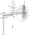
- the figure 1 illustrates an imaging spectrophotometer according to a first embodiment of the invention.
- An object O to be analyzed is disposed in the object plane of the imaging spectrophotometer.
- an illumination assembly ES comprises a source S for transmitting an electromagnetic beam in a given wavelength or a range of wavelengths bound for the object to be irradiated. analyze.
- the spectrophotometer by means of the illumination set ES makes it possible to scan line by line the object O to be analyzed by means of the emission source S.
- the illumination assembly ES comprises a laser source and emits in the visible or infrared ultraviolet range and makes it possible to characterize an object O by its spectral response.
- the object O excited by a wavelength belonging to the ultraviolet range of visible or infrared fires a beam in higher wavelengths ranging from ultraviolet to visible and infrared. It is this fluorescence that makes it possible to characterize the object O to be analyzed.
- the object O to be analyzed may be an adhesive, a resin, a paint, an organic or biological element or any other material or nanomaterial having fluorescent properties.
- the illumination set ES comprises a set L, LC, LLG for shaping the beam emitted by the source in order to illuminate only one line on the object O to be analyzed.
- the illumination assembly ES comprises an injection mirror MI which makes it possible to inject a beam (mark 1) originating from the source S towards the imaging spectrophotometer.
- the beam (mark 3) from the focusing mirror M2 arrives on a first mirror M1 folding and in particular on the front face M11 before the latter.
- the first M1 folding mirror further comprises a rear face M12 also reflective and a slot M1-F in its center.
- the slot M1-F allows to pass the beam and has a width of a few tens of microns for a few millimeters long.
- the shaping of the laser beam must be such that its image through the injection mirror MI is superimposed on the slot M1-F of the first mirror M1 folding.
- the first folding mirror M1 reflects the beam (reference 4) to a rotating mirror M0 mirror mirror which reflects the beam (mark 5) to the object O to be analyzed.
- the illumination of the object O is done laterally with a laser beam covering the analysis zone: the laser forms a line on the zone to be analyzed which corresponds to the field of the imaging spectrophotometer.
- Such a configuration makes it possible to avoid the specular reflection back in the spectrophotometer on the brilliant objects.
- the lighting is done only on the useful area and therefore limits the photo-degradation and heating by the source (for example UV in the case of fluorescence) unanalysed areas.
- the exposure dose is the dose strictly necessary for the analysis.
- measuring sensors C1, C2 which make it possible to measure a distance between the object O and the scanning mirror M0.
- the mirror M2 focussing is itself mobile in translation (along the axis DM2 on the figure 1 ) to adapt the imager to the distance measured by the measuring sensors C1, C2.
- This mobility makes it possible to adapt the focusing plane of the spectrophotometer to the position of the object or to change the plane of focus to measure in the volume of the object.
- the beam from the object O to be analyzed arrives on the front face M11 of the first folding mirror and reflects the beam towards the focusing mirror M2 which focuses the beam towards the slot M1-F of the first folding mirror M1. In this way, the beam passes through the thickness of the first folding mirror M1 via slot M1-F which selects only one line of the object field.
- the beam passing through the slot M1-F arrives at an imaging assembly E i which makes it possible to bring this beam to an E DET detecting assembly which consists solely of a CDD or CMOS sensor.
- the imaging spectrophotometer comprises a device OBT shutter beam disposed in front of the front face M11 of the first mirror and at the slot M1-F of the first mirror.
- the shutter device comprises a vertical blade L wider than the slot M1-F and two stops B1, B2 which define two positions between which the blade L is movable.
- the stops B1, B2 limiting the two positions of the shutter device are adjustable so as to mask the optical beam on the axis at B1, or to hide the direct light from the object O which is not reflected by M1 and running through the slot ..
- the blade is movable in two positions, an open position in which it prevents a direct parasitic beam from the scanning mirror M0 to pass through the slot, the (useful) beam from the object however passes through the slot via M2, and a closed position preventing any beam from passing through the slot M1-F.
- the CCD or CMOS sensor is not lit during its reading, the data transfer and the change of sight
- Such a closure device has the advantage of being robust compared to conventional iris shutters or equivalent system that works with blades that rub on each other. Indeed, the acquisition of a hyperspectral image often represents several hundreds or thousands of acquisitions (opening closing of the shutter device) without counting the settings preceding the shots.
- the imaging assembly E i comprises a mirror M3 of parabolic collimation on which the beam coming from the slot M1-F arrives. The beams are then reflected by this mirror M3 collimation and reflected by the rear face M12 of the first mirror M1 folding.
- the beam reflected by the rear face M12 of the first folding mirror M1 passes through a prism P which disperses the beam according to the wavelengths.
- the scattered beams arrive on a second folding mirror M4 (which is pierced at its center, the hole is circular or rectangular) which reflects the beams to an imaging mirror M5.
- the imaging mirror M5 reflects the beams to the detection assembly.
- the illumination set ES may be further upstream in the imaging spectrophotometer.
- optical path from the object O to the detection set E DET is identical to that of the first embodiment.
- the imaging spectrophotometer according to this second embodiment may comprise a shutter device.
- the optical axes of the source S and the set E detector DET are aligned which means that there is no parallax for all working distances.
- the illumination assembly ES may be at the level of the detection assembly.
- the imaging spectrophotometer according to this third embodiment may comprise a shutter device.
- the figure 6 illustrates a fourth embodiment, according to which the light source S 'of the set ES' of illumination consists of a polychromatic source.
- a luminous flux is emitted in an integrating sphere 11 placed in front of the luminous source S 'which uniformizes the flux through the output port S'-F of the sphere 11, which in this case is a slot with the same geometrical characteristics as the slot M1 -F.
- a part of the flux coming from the slot S'-F of the sphere 11 is oriented towards the collector mirror M2 of the spectrophotometer via a mirror M6.
- the collector mirror M2 illuminates the area of analysis by refocusing the beam of white light from the sphere as if it came from the slot.
- the set ES 'of illumination thus generates an illumination of the analysis zone (in the form of a line).
- a mirror MS 'spherical (or an equivalent occulting surface) pierced with a ring centered on the slot S'-F of the sphere is disposed in front of the sphere.
- the reflected light returns to the sphere.
- the spectrophotometer according to this fourth embodiment may comprise a shutter device.
Landscapes
- Physics & Mathematics (AREA)
- Spectroscopy & Molecular Physics (AREA)
- General Physics & Mathematics (AREA)
- Chemical & Material Sciences (AREA)
- Analytical Chemistry (AREA)
- Optics & Photonics (AREA)
- Health & Medical Sciences (AREA)
- Nuclear Medicine, Radiotherapy & Molecular Imaging (AREA)
- Life Sciences & Earth Sciences (AREA)
- Biochemistry (AREA)
- General Health & Medical Sciences (AREA)
- Immunology (AREA)
- Pathology (AREA)
- Spectrometry And Color Measurement (AREA)
- Investigating Or Analysing Materials By Optical Means (AREA)
- Microscoopes, Condenser (AREA)
Abstract
Description
- L'invention concerne le domaine de l'imagerie hyperspectrale ou spectro-imagerie qui consiste à acquérir une image dans un grand nombre de bandes spectrales étroites.
- Pour acquérir des images hyperspectrales, on connait des instruments catadioptriques (voir les documents
US 5 459 325 etUS 4 215 273 ). Toutefois, ces instruments présentent l'inconvénient d'avoir des lentilles qui induisent un chromatisme et qui de fait ne permet pas d'avoir toutes les longueurs d'ondes. - En outre, ces instruments sont encombrants ce qui s'avère être un inconvénient lorsque l'objet à imager n'est pas accessible simplement.
- L'invention propose de pallier les inconvénients précités.
- A cet effet, l'invention propose un spectrophotomètre imageur hyperspectral large bande configuré pour analyse un objet, ledit spectrophotomètre comprenant
un ensemble d'illumination comprenant une source d'émission d'un faisceau lumineux, ledit ensemble étant configuré pour que le faisceau lumineux balaye ligne par ligne l'objet à analyser ;
un miroir de focalisation ;
un premier miroir de repliement ;
un miroir de balayage plan mobile en rotation ;
l'ensemble d'illumination, le miroir de focalisation, premier miroir de repliement et le miroir plan étant agencés pour amener le faisceaux lumineux vers l'objet selon une ligne qui sera déplacée sur l'objet via le miroir de balayage ;
le spectrophotomètre imageur étant caractérisé en ce qu'il comprend deux capteurs de mesure d'une distance entre l'objet et le miroir de balayage, et en ce que le miroir de focalisation est mobile en translation pour adapter l'imageur à la distance mesurée par lesdits capteurs de mesure. - L'invention est avantageusement complétée par les caractéristiques suivantes, prises seules ou en une quelconque de leur combinaison techniquement possible.
- Le premier miroir de repliement comprend une face avant orientée vers le miroir de focalisation et une face arrière opposée à ladite face avant, ledit premier miroir comprenant une fente configurée pour laisser passer un faisceau issu de l'objet, le spectrophotomètre imageur comprenant un dispositif d'obturation d'un faisceau disposé devant la face avant du premier miroir et devant la fente dudit premier miroir, le dispositif d'obturation comprenant une lame verticale plus large que la fente, ladite lame étant mobile selon deux positions, une position ouverte selon laquelle elle empêche un faisceau parasite direct issu du miroir de balayage de traverser ladite fente, le faisceau issu de l'objet traversant ladite fente, et une position fermée empêchant n'importe quel faisceau de passer par la fente.
- Le dispositif d'obturation comprend une lame noire montée pivotante devant la face avant du premier miroir et deux butées permettant de définir les deux positions.
- La source de l'ensemble d'illumination est configurée pour émettre un faisceau dans le domaine de l'ultra-violet, le visible ou infrarouge, et est de préférence un Laser, l'ensemble d'illumination comprenant en outre un ensemble de mise en forme du faisceau émis par la source afin d'illuminer uniquement une ligne sur l'objet à analyser.
- L'ensemble d'illumination comprend un miroir plan d'injection du faisceau mis en forme vers le miroir de focalisation, le faisceau mis en forme étant tel que son image à travers ledit miroir plan d'injection est superposée à la fente du premier miroir de repliement.
- L'ensemble de mise en forme comprend, dans le sens de propagation du faisceau lumineux, une lentille génératrice d'une raie uniforme en éclairement, une lentille cylindrique collimatrice sur l'axe de la raie, une lentille pour adapter le grandissement.
- L'ensemble d'illumination comprend une sphère intégrante placée devant la source, la sphère comprenant une fente configurée pour laisser passer un faisceau lumineux.
- L'ensemble d'illumination comprend en outre un miroir sphérique percé d'un anneau centré sur la fente de la sphère et est disposé devant la sphère, ledit miroir sphérique étant configuré pour lasser passer un faisceau et pour réfléchir de la lumière et la renvoyer la sphère.
- Le spectrophotomètre comprend un ensemble d'imagerie et un ensemble de détection, l'ensemble d'imagerie étant agencé par rapport au premier miroir pour amener un faisceau provenant de la fente vers l'ensemble de détection.
- L'ensemble de détection comprend un capteur CCD ou CMOS.
- D'autres caractéristiques, buts et avantages de l'invention ressortiront de la description qui suit, qui est purement illustrative et non limitative, et qui doit être lue en regard des dessins annexés sur lesquels :
- la
figure 1 illustre un spectrophotomètre imageur selon un premier mode de réalisation de l'invention ; - les
figures 2 et 3 illustrent un dispositif d'obturation d'un spectrophotomètre imageur selon l'invention ; - la
figure 4 illustre un spectrophotomètre imageur selon un second mode de réalisation de l'invention ; - la
figure 5 illustre un spectrophotomètre imageur selon un troisième mode de réalisation de l'invention ; - la
figure 6 illustre un spectrophotomètre imageur selon un quatrième mode de réalisation de l'invention. - Sur l'ensemble des figures les éléments similaires portent des références identiques.
- La
figure 1 illustre un spectrophotomètre imageur selon un premier mode de réalisation de l'invention. - Un objet O à analyser est disposé dans le plan objet du spectrophotomètre imageur.
- Afin d'éclairer l'objet O, un ensemble ES d'illumination comprend une source S d'émission d'un faisceau électromagnétique dans une longueur d'onde donnée ou un domaine de longueur d'onde donné à destination de l'objet à analyser.
- Le spectrophotomètre au moyen de l'ensemble ES d'illumination permet de balayer ligne par ligne l'objet O à analyser au moyen de la source d'émission S.
- Selon ce premier mode de réalisation, l'ensemble ES d'illumination comprend une source Laser et émet dans le domaine de l'ultra-violet du visible ou de l'infrarouge et permet de caractériser un objet O par sa réponse spectrale.
- L'objet O excité par une longueur d'onde appartenant au domaine de l'ultraviolet du visible ou de l'infrarouge réemet un faisceau dans des longueurs d'onde plus élevées allant de l'Ultra-violet au visible et l'infrarouge. C'est cette fluorescence qui permet de caractériser l'objet O à analyser.
- L'objet O à analyser peut être une colle, une résine, une peinture, un élément organique, biologique ou tout autre matériau ou nanomatériau ayant des propriétés fluorescentes.
- L'ensemble ES d'illumination comprend un ensemble L, LC, LLG de mise en forme du faisceau émis par la source afin d'illuminer uniquement une ligne sur l'objet O à analyser.
- Cet ensemble de mise en forme comprend en particulier trois lentilles L, LC, LLG devant la source d'émission S du faisceau lumineux :
- Lentille LLG : lentille génératrice de raie laser ;
- Lentille LC : lentille cylindrique collimatrice sur l'axe de la raie Laser ;
- Lentille L ou système de lentilles : Lentille pour imager la ligne laser à travers le spectrophotomètre imageur : le grandissement est ajusté à la zone de balayage du spectrophotomètre imageur.
- L'ensemble ES d'illumination comprend un miroir d'injection MI qui permet d'injecter un faisceau (repère 1) issu de la source S vers le spectrophotomètre imageur.
- Un faisceau (repère 2) issu de la réflexion du faisceau issu de la source sur le miroir MI d'injection arrive sur un miroir M2 de focalisation qui est de préférence un miroir sphérique de focalisation.
- Le faisceau (repère 3) issu du miroir M2 de focalisation arrive sur un premier miroir M1 de repliement et notamment sur la face avant M11 avant de ce dernier. Le premier M1 miroir de repliement comprend en outre une face arrière M12 elle aussi réfléchissante et une fente M1-F en son centre. La fente M1-F permet de laisser passer le faisceau et a une largeur de quelques dizaines de microns pour quelques millimètres de long.
- De manière préférée, la mise en forme du faisceau laser doit être telle que son image à travers le miroir d'injection MI soit superposée à la fente M1-F du premier miroir M1 de repliement.
- Le premier miroir M1 de repliement réfléchi le faisceau (repère 4) vers un miroir M0 de balayage plan mobile en rotation lequel réfléchit le faisceau (repère 5) vers l'objet O à analyser.
- De manière avantageuse, l'éclairement de l'objet O se fait latéralement avec un faisceau laser couvrant la zone d'analyse : le laser forme une ligne sur la zone à analyser qui correspond au champ du spectrophotomètre imageur.
- Une telle configuration permet d'éviter la réflexion spéculaire en retour dans le spectrophotomètre sur les objets brillants.
- En outre, l'éclairage se fait uniquement sur la zone utile et limite donc la photo-dégradation et l'échauffement par la source (par exemple UV dans le cas de la fluorescence) des zones non analysées. En conséquence, la dose d'exposition correspond à la dose strictement nécessaire à l'analyse.
- Afin d'effectuer une mise au point, de chaque côté du miroir M0 sont disposés des capteurs C1, C2 de mesure qui permettent de mesurer une distance entre l'objet O et le miroir M0 de balayage. Le miroir M2 de focalisation est quant à lui mobile en translation (selon l'axe DM2 sur la
figure 1 ) pour adapter l'imageur à la distance mesurée par les capteurs C1, C2 de mesure. Cette mobilité permet d'adapter le plan de focalisation du spectrophotomètre à la position de l'objet ou de faire évoluer le plan de focalisation pour mesurer dans le volume de l'objet. - Le faisceau issu de l'objet O à analyser arrive sur la face M11 avant du premier miroir de repliement et réfléchit le faisceau vers le miroir M2 de focalisation lequel focalise le faisceau vers la fente M1-F du premier miroir M1 de repliement. De cette façon, le faisceau traverse l'épaisseur du premier miroir M1 de repliement via la fente M1-F qui ne sélectionne qu'une ligne du champ objet.
- Le faisceau traversant la fente M1-F arrive sur ensemble Ei d'imagerie qui permet d'amener ce faisceau vers un ensemble EDET de détection qui est uniquement constitué d'un capteur CDD ou CMOS.
- Pour permettre l'acquisition des faisceaux, le spectrophotomètre imageur comprend un dispositif OBT d'obturation du faisceau disposé devant la face avant M11 du premier miroir et à hauteur de la fente M1-F de ce premier miroir.
- Comme illustré en détail sur les
figures 2 et 3 , le dispositif d'obturation comprend une lame L verticale plus large que la fente M1-F et deux butées B1, B2 qui définissent deux positions entre lesquelles la lame L est mobile. - Les butées B1, B2 limitant les deux positions du dispositif d'obturation sont réglables soit de manière à masquer le faisceau optique sur l'axe en B1, soit à occulter la lumière directe venant de l'objet O qui n'est pas réfléchie par M1 et qui traverse la fente..
- Ainsi, la lame est mobile selon deux positions, une position ouverte selon laquelle elle empêche un faisceau parasite direct issu du miroir M0 de balayage de passer par la fente, le faisceau (utile) issu de l'objet passe toutefois par la fente via M2, et une position fermée empêchant n'importe quel faisceau de passer par la fente M1-F. Ainsi, le capteur CCD ou CMOS n'est pas éclairé pendant sa lecture, le transfert des données et le changement de visée
- Par conséquent, le dispositif d'obturation a une double fonction :
- Obturer le faisceau à la place d'un obturateur mécanique traditionnel à durée de vie limitée ;
- Supprimer la lumière parasite qui rentre directement dans le spectrophotomètre via le miroir de changement de visée M0 et la fente M1-F ;
- Un tel dispositif d'obturation présente l'avantage d'être robuste comparativement aux obturateurs classiques à iris ou système équivalent qui fonctionne avec des lames qui frottent les unes sur les autres. En effet, l'acquisition d'une image hyperspectrale représente souvent plusieurs centaines ou plusieurs milliers d'acquisitions (ouverture fermeture du dispositif d'obturation) sans compter les réglages précédents les prises de vue.
- Ainsi, avec une le dispositif d'obturation utilisant seulement une lame noire (puisque le champ est imagé sous la forme d'une ligne au niveau de la fente) fixée grâce à une liaison pivot bloqué (sur roulements à bille par exemple), il n'y a pas de frottements comme entre les volets d'un obturateur classique pour pupille circulaire, et donc pas d'usure prématurée. Une translation au niveau d'une liaison pivot est également possible.
- L'ensemble Ei d'imagerie comprend un miroir M3 de collimation parabolique sur lequel arrive le faisceau issu de la fente M1-F. Les faisceaux sont alors réfléchis par ce miroir M3 de collimation et réfléchis par la face M12 arrière du premier miroir M1 de repliement.
- Le faisceau réfléchi par la face M12 arrière du premier miroir M1 de repliement passe par un prisme P qui disperse le faisceau selon les longueurs d'onde. Les faisceaux dispersés arrivent sur un second miroir M4 de repliement (qui est percé en son centre, le perçage est circulaire ou rectangulaire) qui réfléchit les faisceaux vers un miroir M5 d'imagerie. Le miroir M5 d'imagerie réfléchit les faisceaux vers l'ensemble de détection.
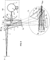
- Selon un second mode de réalisation, illustré sur la
figure 4 , l'ensemble ES d'illumination peut être plus en amont dans le spectrophotomètre imageur. - Selon ce second mode de réalisation, le chemin optique pour aller de l'ensemble ES d'illumination est le suivant :
- Un faisceau (repère 1) issu de la source S arrive sur le miroir MI d'injection qui amène le faisceau (repère 2) vers la face M12 arrière du premier miroir M1 de repliement lequel réfléchit le faisceau (repère 3) vers le miroir M3 de collimation ;
- Le miroir M3 de collimation réfléchit le faisceau (repère 4) vers le miroir M2 de collimation ;
- Le miroir M2 de collimation réfléchit le faisceau (repère 5) vers la face M11 avant du premier miroir M1 de repliement ;
- Le miroir M1 de repliement réfléchit le faisceau (repère 6) vers le miroir M0 de balayage ;
- Le miroir M0 de balayage réfléchit le faisceau (repère 7) vers l'objet O à analyser.
- Le chemin optique de l'objet O vers l'ensemble EDET de détection est identique à celui du premier mode de réalisation.
- Les différents miroirs de ce second mode de réalisation ainsi que l'ensemble d'imagerie sont identiques au premier mode de réalisation. En outre, le spectrophotomètre imageur selon ce second mode de réalisation peut comprendre un dispositif d'obturation.
- Selon un troisième mode de réalisation, illustré sur la
figure 5 , les axes optiques de la source S et de l'ensemble EDET de détection sont alignés ce qui implique qu'il n'y a pas de parallaxe pour toutes les distances de travail. L'ensemble ES d'illumination peut être au niveau de l'ensemble de détection. - Selon ce troisième mode de réalisation on remarque que l'ensemble d'illumination ne comprend pas de miroir d'injection :
- un faisceau (repère 1) issu de la source S passe par la zone percée du miroir M4 et arrive sur le prisme P et traverse le prisme P (repère 2);
- le faisceau issu du prisme (repère 3) arrive sur le premier miroir M1 de repliement lequel réfléchi le faisceau (repère 4) vers le miroir M3 de collimation qui à son tour réfléchit le faisceau (repère 5) vers le premier miroir M1 de repliement ;
- le faisceau issu du premier miroir de repliement (repère 6) arrive sur le miroir M2 de collimation lequel réfléchit le faisceau (repère 7) vers le premier miroir M1 de repliement qui est à son tour réfléchi par le premier miroir M1 de repliement vers le miroir M0 de balayage (repère 8) ;
- le faisceau réfléchi par le miroir M0 de balayage arrive sur l'objet O à analyser.
- Les différents miroirs de ce troisième mode de réalisation ainsi que l'ensemble d'imagerie sont identiques au premier mode de réalisation. En outre, le spectrophotomètre imageur selon ce troisième mode de réalisation peut comprendre un dispositif d'obturation.
- La
figure 6 illustre un quatrième mode de réalisation, selon lequel la source S' lumineuse de l'ensemble ES' d'illumination est constituée d'une source polychromatique. Un flux lumineux est émis dans une sphère intégrante 11 placée devant la source S' lumineuse qui uniformise le flux à travers le port S'-F de sortie de la sphère 11 qui est dans ce cas une fente de mêmes caractéristiques géométriques que la fente M1-F. - Une partie du flux issue de la fente S'-F de la sphère 11 est orienté vers le miroir collecteur M2 du spectrophotomètre via un miroir M6. Le miroir collecteur M2 éclaire la zone d'analyse en refocalisant le faisceau de lumière blanche issu de la sphère comme s'il venait de la fente. Ici aussi, l'ensemble ES' d'illumination génère donc un éclairement de la zone d'analyse (en forme de ligne).
- De manière complémentaire, un miroir MS' sphérique (ou une surface occultante équivalente) percé d'un anneau centré sur la fente S'-F de la sphère est disposé devant la sphère. Dans le cas d'un miroir sphérique, la lumière réfléchie retourne dans la sphère.
- Jusqu'à l'objet O, le chemin optique est le suivant :
- Le faisceau (repères 1, 1') issu de la sphère est réfléchi par le miroir M6 vers le miroir M2 de focalisation (repères 2, 2') ;
- Le faisceau 2, 2' issu du miroir M2 de focalisation arrive alors sur le premier miroir M1 de repliement ;
- Le faisceau (repères 3, 3') est alors réfléchi vers le premier miroir M1 de repliement lequel réfléchit le faisceau (repères 4, 4') vers le miroir M0 de balayage ;
- Le miroir M0 de balayage réfléchit le faisceau (repères 5, 5') vers l'objet O à analyser.
- Ce quatrième mode est avantageux pour les raisons suivantes :
- L'éclairage est intégré dans le spectrophotomètre imageur ;
- Seule la zone utile est éclairée quel que soit la distance de travail ;
- Le balayage est synchrone avec la source ;
- L'étalonnage de l'éclairement sur la ligne se fait en une seule acquisition sur un plan uniforme et permet ensuite des corrections radiométriques d'uniformité.
- Les différents miroirs de ce quatrième mode de réalisation ainsi que l'ensemble d'imagerie sont identiques au premier mode de réalisation. En outre, le spectrophotomètre selon ce quatrième mode de réalisation peut comprendre un dispositif d'obturation.
Claims (10)
- Spectrophotomètre imageur hyperspectral large bande configuré pour analyse un objet (O), ledit spectrophotomètre comprenantun ensemble (ES, ES') d'illumination comprenant une source (S, S') d'émission d'un faisceau lumineux, ledit ensemble étant configuré pour que le faisceau lumineux balaye ligne par ligne l'objet à analyser (O) ;un miroir (M2) de focalisation ;un premier miroir (M1) de repliement ;un miroir (M0) de balayage plan mobile en rotation ;l'ensemble d'illumination, le miroir (M2) de focalisation, premier miroir (M1) de repliement et le miroir (M0) plan étant agencés pour amener le faisceaux lumineux vers l'objet selon une ligne qui sera déplacée sur l'objet via le miroir (M0) de balayage ;le spectrophotomètre imageur étant caractérisé en ce qu'il comprend deux capteurs (C1, C2) de mesure d'une distance entre l'objet (O) et le miroir (M0) de balayage, et en ce que le miroir (M2) de focalisation est mobile en translation pour adapter l'imageur à la distance mesurée par lesdits capteurs de mesure.
- Spectrophotomètre imageur selon la revendication 1, dans lequel le premier miroir (M1) de repliement comprend une face avant (M11) orientée vers le miroir (M2) de focalisation et une face arrière (M12) opposée à ladite face (M11) avant, ledit premier miroir (M1) comprenant une fente (M1-F) configurée pour laisser passer un faisceau issu de l'objet, le spectrophotomètre imageur comprenant un dispositif (OBT) d'obturation d'un faisceau disposé devant la face avant (M11) du premier miroir (M1) et devant la fente (M1-F) dudit premier miroir, le dispositif d'obturation comprenant une lame verticale plus large que la fente, ladite lame étant mobile selon deux positions, une position ouverte selon laquelle elle empêche un faisceau parasite direct issu du miroir (M0) de balayage de traverser ladite fente, le faisceau issu de l'objet traversant ladite fente, et une position fermée empêchant le faisceau issu de l'objet de passer par la fente (M1-F).
- Spectrophotomètre imageur selon la revendication 2, dans lequel le dispositif (OBT) d'obturation comprend une lame noire montée pivotante devant la face avant du premier miroir et deux butées (B1, B2) permettant de définir les deux positions.
- Spectrophotomètre imageur selon l'une des revendications précédentes, dans lequel la source (S) de l'ensemble (ES) d'illumination est configurée pour émettre un faisceau dans le domaine de l'ultra-violet, le visible ou infrarouge, et est de préférence un Laser, l'ensemble d'illumination comprenant en outre un ensemble (L, LC, LLG) de mise en forme du faisceau émis par la source afin d'illuminer uniquement une ligne sur l'objet (O) à analyser.
- Spectrophotomètre selon l'une des revendications précédentes, dans lequel l'ensemble (ES) d'illumination comprend un miroir plan (MI) d'injection du faisceau mis en forme vers le miroir (M2) de focalisation, le faisceau mis en forme étant tel que son image à travers ledit miroir plan d'injection est superposée à la fente (M1-F) du premier miroir (M1) de repliement.
- Spectrophotomètre imageur selon la revendication précédente, dans lequel l'ensemble de mise en forme comprend, dans le sens de propagation du faisceau lumineux, une lentille (LLG) génératrice d'une raie uniforme en éclairement, une lentille (LC) cylindrique collimatrice sur l'axe de la raie, une lentille (L) pour adapter le grandissement.
- Spectrophotomètre imageur selon l'une des revendications 1 à 4, dans lequel l'ensemble (ES') d'illumination comprend une sphère (11) intégrante placée devant la source (S'), la sphère (11) comprenant une fente (S'-F) configurée pour laisser passer un faisceau lumineux.
- Spectrophotomètre imageur selon la revendication précédente, dans lequel l'ensemble (ES') d'illumination comprend en outre un miroir sphérique (MS') percé d'un anneau centré sur la fente (S'-F) de la sphère et est disposé devant la sphère, ledit miroir sphérique (MS') étant configuré pour lasser passer un faisceau et pour réfléchir de la lumière et la renvoyer la sphère (11).
- Spectrophotomètre imageur selon l'une des revendications 2 à 8, comprenant un ensemble (Ei) d'imagerie et un ensemble (EDET) de détection, l'ensemble d'imagerie étant agencé par rapport au premier miroir (M1) pour amener un faisceau provenant de la fente (F) vers l'ensemble (EDET) de détection.
- Spectrophotomètre imageur selon la revendication précédente, dans lequel l'ensemble (EDET) de détection comprend un capteur CCD ou CMOS.
Applications Claiming Priority (1)
| Application Number | Priority Date | Filing Date | Title |
|---|---|---|---|
| FR1756384A FR3068780B1 (fr) | 2017-07-06 | 2017-07-06 | Spectrophotometre hyperspectral large bande |
Publications (3)
| Publication Number | Publication Date |
|---|---|
| EP3425354A1 true EP3425354A1 (fr) | 2019-01-09 |
| EP3425354B1 EP3425354B1 (fr) | 2023-07-12 |
| EP3425354C0 EP3425354C0 (fr) | 2023-07-12 |
Family
ID=60515464
Family Applications (1)
| Application Number | Title | Priority Date | Filing Date |
|---|---|---|---|
| EP18180891.6A Active EP3425354B1 (fr) | 2017-07-06 | 2018-06-29 | Spectrophotomètre hyperspectral large bande |
Country Status (4)
| Country | Link |
|---|---|
| US (1) | US11079582B2 (fr) |
| EP (1) | EP3425354B1 (fr) |
| JP (1) | JP7064398B2 (fr) |
| FR (1) | FR3068780B1 (fr) |
Families Citing this family (1)
| Publication number | Priority date | Publication date | Assignee | Title |
|---|---|---|---|---|
| JP2024546080A (ja) * | 2021-12-02 | 2024-12-17 | エンスペクトラ・ヘルス・インコーポレイテッド | 光操作のためのシステム及び方法 |
Citations (7)
| Publication number | Priority date | Publication date | Assignee | Title |
|---|---|---|---|---|
| US4215273A (en) | 1979-03-29 | 1980-07-29 | Nasa | Multispectral scanner optical system |
| US5459325A (en) | 1994-07-19 | 1995-10-17 | Molecular Dynamics, Inc. | High-speed fluorescence scanner |
| US20020163715A1 (en) * | 2001-05-04 | 2002-11-07 | Leica Microsystems Heidelberg Gmbh | Microscope, and method for operating a microscope |
| US6909540B2 (en) * | 2001-12-03 | 2005-06-21 | Leica Microsystems Heidelberg Gmbh | Microscope objective, microscope, and method for imaging a specimen |
| US20050280906A1 (en) * | 2004-06-17 | 2005-12-22 | Nova Measuring Instruments Ltd. | Reflective optical system |
| US7335898B2 (en) * | 2004-07-23 | 2008-02-26 | Ge Healthcare Niagara Inc. | Method and apparatus for fluorescent confocal microscopy |
| WO2015071181A1 (fr) * | 2013-11-12 | 2015-05-21 | Centre National D'etudes Spatiales | Spectrophotomètre hyperspectral large bande pour analyser un objet dans le domaine fluorescent |
Family Cites Families (19)
| Publication number | Priority date | Publication date | Assignee | Title |
|---|---|---|---|---|
| JPS62125313A (ja) * | 1985-11-27 | 1987-06-06 | Hitachi Ltd | 顕微鏡の照明装置 |
| JPH02289808A (ja) * | 1989-04-28 | 1990-11-29 | Olympus Optical Co Ltd | 照明光学系 |
| JP2689359B2 (ja) * | 1991-04-20 | 1997-12-10 | 日商精密光学 株式会社 | 光切断顕微鏡 |
| JPH06207857A (ja) * | 1993-01-12 | 1994-07-26 | Minolta Camera Co Ltd | 色彩計測装置 |
| JP3203972B2 (ja) * | 1994-09-16 | 2001-09-04 | 三菱電機株式会社 | 波面センサ |
| JP3745810B2 (ja) * | 1996-01-19 | 2006-02-15 | 本田技研工業株式会社 | レーザ加工方法および装置 |
| JP3615045B2 (ja) * | 1998-03-12 | 2005-01-26 | 本田技研工業株式会社 | レーザ加工装置の制御方法 |
| JP3830121B2 (ja) * | 1999-06-10 | 2006-10-04 | 株式会社 ニューコム | 物体検出用光学ユニット及びそれを用いた位置座標入力装置 |
| JP4066629B2 (ja) * | 2001-09-14 | 2008-03-26 | コニカミノルタセンシング株式会社 | 3次元形状測定光学系 |
| IL149016A0 (en) * | 2002-04-07 | 2004-03-28 | Green Vision Systems Ltd Green | Method and device for real time high speed high resolution spectral imaging |
| US20050280892A1 (en) * | 2004-05-28 | 2005-12-22 | Nobuyuki Nagasawa | Examination method and examination apparatus |
| DE102007047465A1 (de) * | 2007-09-28 | 2009-04-02 | Carl Zeiss Microimaging Gmbh | Verfahren und Anordnung zur optischen Erfassung einer beleuchteten Probe |
| JP2009236546A (ja) * | 2008-03-26 | 2009-10-15 | Univ Of Tokyo | 標準光源装置 |
| JP2011022553A (ja) * | 2009-06-15 | 2011-02-03 | Nikon Corp | 照明光学系 |
| US20140078509A1 (en) * | 2011-05-02 | 2014-03-20 | Green Vision Systems Ltd. | Microelectromechanical system (mems) and (mem) optical interferometer for hyper-spectral imaging and analysis |
| JP5730671B2 (ja) * | 2011-05-31 | 2015-06-10 | オリンパス株式会社 | ズーム結像光学系、及び、それを備えた顕微鏡 |
| DE102012020240A1 (de) * | 2012-10-12 | 2014-04-17 | Carl Zeiss Microscopy Gmbh | Mikroskop und Verfahren zur SPIM Mikroskopie |
| CN102967604B (zh) * | 2012-11-06 | 2014-11-05 | 广州标旗电子科技有限公司 | 一种用于宝石检测的反射光谱测量取样系统及方法 |
| JP6768289B2 (ja) * | 2015-12-01 | 2020-10-14 | キヤノン株式会社 | 走査型顕微鏡 |
-
2017
- 2017-07-06 FR FR1756384A patent/FR3068780B1/fr active Active
-
2018
- 2018-06-29 EP EP18180891.6A patent/EP3425354B1/fr active Active
- 2018-07-04 JP JP2018127828A patent/JP7064398B2/ja active Active
- 2018-07-06 US US16/028,695 patent/US11079582B2/en active Active
Patent Citations (7)
| Publication number | Priority date | Publication date | Assignee | Title |
|---|---|---|---|---|
| US4215273A (en) | 1979-03-29 | 1980-07-29 | Nasa | Multispectral scanner optical system |
| US5459325A (en) | 1994-07-19 | 1995-10-17 | Molecular Dynamics, Inc. | High-speed fluorescence scanner |
| US20020163715A1 (en) * | 2001-05-04 | 2002-11-07 | Leica Microsystems Heidelberg Gmbh | Microscope, and method for operating a microscope |
| US6909540B2 (en) * | 2001-12-03 | 2005-06-21 | Leica Microsystems Heidelberg Gmbh | Microscope objective, microscope, and method for imaging a specimen |
| US20050280906A1 (en) * | 2004-06-17 | 2005-12-22 | Nova Measuring Instruments Ltd. | Reflective optical system |
| US7335898B2 (en) * | 2004-07-23 | 2008-02-26 | Ge Healthcare Niagara Inc. | Method and apparatus for fluorescent confocal microscopy |
| WO2015071181A1 (fr) * | 2013-11-12 | 2015-05-21 | Centre National D'etudes Spatiales | Spectrophotomètre hyperspectral large bande pour analyser un objet dans le domaine fluorescent |
Also Published As
| Publication number | Publication date |
|---|---|
| JP7064398B2 (ja) | 2022-05-10 |
| EP3425354B1 (fr) | 2023-07-12 |
| EP3425354C0 (fr) | 2023-07-12 |
| US20190018230A1 (en) | 2019-01-17 |
| US11079582B2 (en) | 2021-08-03 |
| FR3068780B1 (fr) | 2021-05-14 |
| JP2019053036A (ja) | 2019-04-04 |
| FR3068780A1 (fr) | 2019-01-11 |
Similar Documents
| Publication | Publication Date | Title |
|---|---|---|
| EP2741310B1 (fr) | Système de détection de cathodoluminescence optimisant la collection du signal, la résolution spectrale et la conservation de la brillance, et microscope mettant en oeuvre un tel système | |
| FR2652166A1 (fr) | Dispositif d'harmonisation automatique pour un systeme optronique. | |
| FR3020141A1 (fr) | Appareil et procede de microscopie a balayage de faisceau optique | |
| HU229699B1 (hu) | Pinhole kamerát alkalmazó, leképzõ optikai vizsgálóberendezés (reflektométer, polariméter, ellipszométer) | |
| CN205655922U (zh) | 漫反射分光镜仪器 | |
| EP2577706B1 (fr) | Systeme de detection de cathodoluminescence souple et microscope mettant en oeuvre un tel systeme | |
| FR3017210A1 (fr) | Spectrometre et systeme d'analyse de fluide | |
| US10436641B2 (en) | Shutter assembly for calibration | |
| EP1084379B1 (fr) | Acquisition opto électrique de formes par codage chromatique avec des plans d'illumination | |
| FR3001049A1 (fr) | Dispositif de controle optique d'un systeme d'imagerie | |
| KR20020046147A (ko) | 분광 반사율 측정 장치 및 분광 반사율 측정 방법 | |
| EP3899460B1 (fr) | Appareil et procédé de micro-spectrométrie à balayage de faisceau lumineux | |
| JPH07509315A (ja) | レンゾメータ用の分光計 | |
| EP3054281B1 (fr) | Dispositif de mesure d'un signal optique rétrodiffusé par un échantillon | |
| EP3425354B1 (fr) | Spectrophotomètre hyperspectral large bande | |
| CN106092968A (zh) | 光学检测装置及方法 | |
| KR102070295B1 (ko) | 농축산물 성분 검사용 모듈 및 휴대형 검사장치 | |
| EP3069113B1 (fr) | Spectrophotomètre hyperspectral large bande pour analyser un objet dans le domaine fluorescent | |
| FR3061849A1 (fr) | Procede et dispositif de mesure de la fluorescence emise a la surface d'un tissu biologique | |
| FR3051278A1 (fr) | Procede d'etalonnage d'un spectre obtenu a l'aide d'un appareil electronique equipe d'un accessoire amovible. | |
| BE1022447B1 (fr) | Dispositif de focalisation d'un faisceau laser par camera (ii) | |
| WO2016203163A1 (fr) | Système et procédé de collection pour spectroscopie optique | |
| FR2776067A1 (fr) | Systeme de determination et de quantification de l'alignement d'un objet avec une optique de couplage et un dispositif de prise de vues | |
| KR20210078335A (ko) | 분광 반사 계측 장치 | |
| CN112236665A (zh) | 用于光谱分析的装置 |
Legal Events
| Date | Code | Title | Description |
|---|---|---|---|
| PUAI | Public reference made under article 153(3) epc to a published international application that has entered the european phase |
Free format text: ORIGINAL CODE: 0009012 |
|
| STAA | Information on the status of an ep patent application or granted ep patent |
Free format text: STATUS: THE APPLICATION HAS BEEN PUBLISHED |
|
| AK | Designated contracting states |
Kind code of ref document: A1 Designated state(s): AL AT BE BG CH CY CZ DE DK EE ES FI FR GB GR HR HU IE IS IT LI LT LU LV MC MK MT NL NO PL PT RO RS SE SI SK SM TR |
|
| AX | Request for extension of the european patent |
Extension state: BA ME |
|
| STAA | Information on the status of an ep patent application or granted ep patent |
Free format text: STATUS: REQUEST FOR EXAMINATION WAS MADE |
|
| 17P | Request for examination filed |
Effective date: 20190702 |
|
| RBV | Designated contracting states (corrected) |
Designated state(s): AL AT BE BG CH CY CZ DE DK EE ES FI FR GB GR HR HU IE IS IT LI LT LU LV MC MK MT NL NO PL PT RO RS SE SI SK SM TR |
|
| RAP1 | Party data changed (applicant data changed or rights of an application transferred) |
Owner name: SORBONNE UNIVERSITE Owner name: CENTRE NATIONAL D'ETUDES SPATIALES Owner name: CENTRE NATIONAL DE LA RECHERCHE SCIENTIFIQUE |
|
| STAA | Information on the status of an ep patent application or granted ep patent |
Free format text: STATUS: EXAMINATION IS IN PROGRESS |
|
| 17Q | First examination report despatched |
Effective date: 20220118 |
|
| GRAP | Despatch of communication of intention to grant a patent |
Free format text: ORIGINAL CODE: EPIDOSNIGR1 |
|
| STAA | Information on the status of an ep patent application or granted ep patent |
Free format text: STATUS: GRANT OF PATENT IS INTENDED |
|
| INTG | Intention to grant announced |
Effective date: 20230207 |
|
| GRAS | Grant fee paid |
Free format text: ORIGINAL CODE: EPIDOSNIGR3 |
|
| GRAA | (expected) grant |
Free format text: ORIGINAL CODE: 0009210 |
|
| STAA | Information on the status of an ep patent application or granted ep patent |
Free format text: STATUS: THE PATENT HAS BEEN GRANTED |
|
| AK | Designated contracting states |
Kind code of ref document: B1 Designated state(s): AL AT BE BG CH CY CZ DE DK EE ES FI FR GB GR HR HU IE IS IT LI LT LU LV MC MK MT NL NO PL PT RO RS SE SI SK SM TR |
|
| P01 | Opt-out of the competence of the unified patent court (upc) registered |
Effective date: 20230601 |
|
| REG | Reference to a national code |
Ref country code: CH Ref legal event code: EP |
|
| REG | Reference to a national code |
Ref country code: DE Ref legal event code: R096 Ref document number: 602018053100 Country of ref document: DE |
|
| REG | Reference to a national code |
Ref country code: IE Ref legal event code: FG4D Free format text: LANGUAGE OF EP DOCUMENT: FRENCH |
|
| U01 | Request for unitary effect filed |
Effective date: 20230718 |
|
| U07 | Unitary effect registered |
Designated state(s): AT BE BG DE DK EE FI FR IT LT LU LV MT NL PT SE SI Effective date: 20230725 |
|
| P04 | Withdrawal of opt-out of the competence of the unified patent court (upc) registered |
Effective date: 20230721 |
|
| REG | Reference to a national code |
Ref country code: LT Ref legal event code: MG9D |
|
| PG25 | Lapsed in a contracting state [announced via postgrant information from national office to epo] |
Ref country code: GR Free format text: LAPSE BECAUSE OF FAILURE TO SUBMIT A TRANSLATION OF THE DESCRIPTION OR TO PAY THE FEE WITHIN THE PRESCRIBED TIME-LIMIT Effective date: 20231013 |
|
| PG25 | Lapsed in a contracting state [announced via postgrant information from national office to epo] |
Ref country code: ES Free format text: LAPSE BECAUSE OF FAILURE TO SUBMIT A TRANSLATION OF THE DESCRIPTION OR TO PAY THE FEE WITHIN THE PRESCRIBED TIME-LIMIT Effective date: 20230712 |
|
| PG25 | Lapsed in a contracting state [announced via postgrant information from national office to epo] |
Ref country code: IS Free format text: LAPSE BECAUSE OF FAILURE TO SUBMIT A TRANSLATION OF THE DESCRIPTION OR TO PAY THE FEE WITHIN THE PRESCRIBED TIME-LIMIT Effective date: 20231112 |
|
| PG25 | Lapsed in a contracting state [announced via postgrant information from national office to epo] |
Ref country code: RS Free format text: LAPSE BECAUSE OF FAILURE TO SUBMIT A TRANSLATION OF THE DESCRIPTION OR TO PAY THE FEE WITHIN THE PRESCRIBED TIME-LIMIT Effective date: 20230712 Ref country code: NO Free format text: LAPSE BECAUSE OF FAILURE TO SUBMIT A TRANSLATION OF THE DESCRIPTION OR TO PAY THE FEE WITHIN THE PRESCRIBED TIME-LIMIT Effective date: 20231012 Ref country code: IS Free format text: LAPSE BECAUSE OF FAILURE TO SUBMIT A TRANSLATION OF THE DESCRIPTION OR TO PAY THE FEE WITHIN THE PRESCRIBED TIME-LIMIT Effective date: 20231112 Ref country code: HR Free format text: LAPSE BECAUSE OF FAILURE TO SUBMIT A TRANSLATION OF THE DESCRIPTION OR TO PAY THE FEE WITHIN THE PRESCRIBED TIME-LIMIT Effective date: 20230712 Ref country code: GR Free format text: LAPSE BECAUSE OF FAILURE TO SUBMIT A TRANSLATION OF THE DESCRIPTION OR TO PAY THE FEE WITHIN THE PRESCRIBED TIME-LIMIT Effective date: 20231013 Ref country code: ES Free format text: LAPSE BECAUSE OF FAILURE TO SUBMIT A TRANSLATION OF THE DESCRIPTION OR TO PAY THE FEE WITHIN THE PRESCRIBED TIME-LIMIT Effective date: 20230712 |
|
| PG25 | Lapsed in a contracting state [announced via postgrant information from national office to epo] |
Ref country code: PL Free format text: LAPSE BECAUSE OF FAILURE TO SUBMIT A TRANSLATION OF THE DESCRIPTION OR TO PAY THE FEE WITHIN THE PRESCRIBED TIME-LIMIT Effective date: 20230712 |
|
| REG | Reference to a national code |
Ref country code: DE Ref legal event code: R097 Ref document number: 602018053100 Country of ref document: DE |
|
| PG25 | Lapsed in a contracting state [announced via postgrant information from national office to epo] |
Ref country code: SM Free format text: LAPSE BECAUSE OF FAILURE TO SUBMIT A TRANSLATION OF THE DESCRIPTION OR TO PAY THE FEE WITHIN THE PRESCRIBED TIME-LIMIT Effective date: 20230712 Ref country code: RO Free format text: LAPSE BECAUSE OF FAILURE TO SUBMIT A TRANSLATION OF THE DESCRIPTION OR TO PAY THE FEE WITHIN THE PRESCRIBED TIME-LIMIT Effective date: 20230712 Ref country code: CZ Free format text: LAPSE BECAUSE OF FAILURE TO SUBMIT A TRANSLATION OF THE DESCRIPTION OR TO PAY THE FEE WITHIN THE PRESCRIBED TIME-LIMIT Effective date: 20230712 Ref country code: SK Free format text: LAPSE BECAUSE OF FAILURE TO SUBMIT A TRANSLATION OF THE DESCRIPTION OR TO PAY THE FEE WITHIN THE PRESCRIBED TIME-LIMIT Effective date: 20230712 |
|
| PLBE | No opposition filed within time limit |
Free format text: ORIGINAL CODE: 0009261 |
|
| STAA | Information on the status of an ep patent application or granted ep patent |
Free format text: STATUS: NO OPPOSITION FILED WITHIN TIME LIMIT |
|
| 26N | No opposition filed |
Effective date: 20240415 |
|
| U20 | Renewal fee for the european patent with unitary effect paid |
Year of fee payment: 7 Effective date: 20240517 |
|
| P05 | Withdrawal of opt-out of the competence of the unified patent court (upc) changed |
Free format text: CASE NUMBER: APP_552687/2023 Effective date: 20230725 |
|
| PG25 | Lapsed in a contracting state [announced via postgrant information from national office to epo] |
Ref country code: MC Free format text: LAPSE BECAUSE OF FAILURE TO SUBMIT A TRANSLATION OF THE DESCRIPTION OR TO PAY THE FEE WITHIN THE PRESCRIBED TIME-LIMIT Effective date: 20230712 |
|
| REG | Reference to a national code |
Ref country code: CH Ref legal event code: PL |
|
| GBPC | Gb: european patent ceased through non-payment of renewal fee |
Effective date: 20240629 |
|
| PG25 | Lapsed in a contracting state [announced via postgrant information from national office to epo] |
Ref country code: IE Free format text: LAPSE BECAUSE OF NON-PAYMENT OF DUE FEES Effective date: 20240629 |
|
| PG25 | Lapsed in a contracting state [announced via postgrant information from national office to epo] |
Ref country code: CH Free format text: LAPSE BECAUSE OF NON-PAYMENT OF DUE FEES Effective date: 20240630 |
|
| PG25 | Lapsed in a contracting state [announced via postgrant information from national office to epo] |
Ref country code: GB Free format text: LAPSE BECAUSE OF NON-PAYMENT OF DUE FEES Effective date: 20240629 |
|
| U20 | Renewal fee for the european patent with unitary effect paid |
Year of fee payment: 8 Effective date: 20250521 |
|
| PG25 | Lapsed in a contracting state [announced via postgrant information from national office to epo] |
Ref country code: CY Free format text: LAPSE BECAUSE OF FAILURE TO SUBMIT A TRANSLATION OF THE DESCRIPTION OR TO PAY THE FEE WITHIN THE PRESCRIBED TIME-LIMIT; INVALID AB INITIO Effective date: 20180629 |
|
| PG25 | Lapsed in a contracting state [announced via postgrant information from national office to epo] |
Ref country code: HU Free format text: LAPSE BECAUSE OF FAILURE TO SUBMIT A TRANSLATION OF THE DESCRIPTION OR TO PAY THE FEE WITHIN THE PRESCRIBED TIME-LIMIT; INVALID AB INITIO Effective date: 20180629 |