EP3425307A1 - Verfahren zur steuerung eines wärmepumpensystems - Google Patents
Verfahren zur steuerung eines wärmepumpensystems Download PDFInfo
- Publication number
- EP3425307A1 EP3425307A1 EP17179286.4A EP17179286A EP3425307A1 EP 3425307 A1 EP3425307 A1 EP 3425307A1 EP 17179286 A EP17179286 A EP 17179286A EP 3425307 A1 EP3425307 A1 EP 3425307A1
- Authority
- EP
- European Patent Office
- Prior art keywords
- electric motor
- control mode
- controlling
- stator current
- pump system
- Prior art date
- Legal status (The legal status is an assumption and is not a legal conclusion. Google has not performed a legal analysis and makes no representation as to the accuracy of the status listed.)
- Pending
Links
- 238000000034 method Methods 0.000 title claims abstract description 42
- 239000012530 fluid Substances 0.000 claims abstract description 65
- 238000010438 heat treatment Methods 0.000 claims abstract description 35
- 238000004804 winding Methods 0.000 claims description 9
- 239000007788 liquid Substances 0.000 claims description 8
- 230000000737 periodic effect Effects 0.000 claims description 6
- 238000004590 computer program Methods 0.000 claims description 3
- 239000013598 vector Substances 0.000 description 9
- 238000001816 cooling Methods 0.000 description 5
- 230000006835 compression Effects 0.000 description 4
- 238000007906 compression Methods 0.000 description 4
- 230000004907 flux Effects 0.000 description 4
- 238000004364 calculation method Methods 0.000 description 3
- 238000011217 control strategy Methods 0.000 description 3
- 230000003247 decreasing effect Effects 0.000 description 3
- 101000841267 Homo sapiens Long chain 3-hydroxyacyl-CoA dehydrogenase Proteins 0.000 description 2
- 102100029107 Long chain 3-hydroxyacyl-CoA dehydrogenase Human genes 0.000 description 2
- 239000002826 coolant Substances 0.000 description 2
- 230000001419 dependent effect Effects 0.000 description 2
- 238000010586 diagram Methods 0.000 description 2
- 238000005259 measurement Methods 0.000 description 2
- JJYKJUXBWFATTE-UHFFFAOYSA-N mosher's acid Chemical compound COC(C(O)=O)(C(F)(F)F)C1=CC=CC=C1 JJYKJUXBWFATTE-UHFFFAOYSA-N 0.000 description 2
- 238000010257 thawing Methods 0.000 description 2
- 238000012546 transfer Methods 0.000 description 2
- 238000004378 air conditioning Methods 0.000 description 1
- 238000009529 body temperature measurement Methods 0.000 description 1
- 239000004020 conductor Substances 0.000 description 1
- 238000013461 design Methods 0.000 description 1
- 230000002349 favourable effect Effects 0.000 description 1
- 238000012986 modification Methods 0.000 description 1
- 230000004048 modification Effects 0.000 description 1
- 230000001360 synchronised effect Effects 0.000 description 1
- 238000009834 vaporization Methods 0.000 description 1
- 238000009423 ventilation Methods 0.000 description 1
- XLYOFNOQVPJJNP-UHFFFAOYSA-N water Substances O XLYOFNOQVPJJNP-UHFFFAOYSA-N 0.000 description 1
Images


Classifications
-
- F—MECHANICAL ENGINEERING; LIGHTING; HEATING; WEAPONS; BLASTING
- F25—REFRIGERATION OR COOLING; COMBINED HEATING AND REFRIGERATION SYSTEMS; HEAT PUMP SYSTEMS; MANUFACTURE OR STORAGE OF ICE; LIQUEFACTION SOLIDIFICATION OF GASES
- F25B—REFRIGERATION MACHINES, PLANTS OR SYSTEMS; COMBINED HEATING AND REFRIGERATION SYSTEMS; HEAT PUMP SYSTEMS
- F25B27/00—Machines, plants or systems, using particular sources of energy
- F25B27/02—Machines, plants or systems, using particular sources of energy using waste heat, e.g. from internal-combustion engines
-
- F—MECHANICAL ENGINEERING; LIGHTING; HEATING; WEAPONS; BLASTING
- F25—REFRIGERATION OR COOLING; COMBINED HEATING AND REFRIGERATION SYSTEMS; HEAT PUMP SYSTEMS; MANUFACTURE OR STORAGE OF ICE; LIQUEFACTION SOLIDIFICATION OF GASES
- F25B—REFRIGERATION MACHINES, PLANTS OR SYSTEMS; COMBINED HEATING AND REFRIGERATION SYSTEMS; HEAT PUMP SYSTEMS
- F25B25/00—Machines, plants or systems, using a combination of modes of operation covered by two or more of the groups F25B1/00 - F25B23/00
- F25B25/005—Machines, plants or systems, using a combination of modes of operation covered by two or more of the groups F25B1/00 - F25B23/00 using primary and secondary systems
-
- F—MECHANICAL ENGINEERING; LIGHTING; HEATING; WEAPONS; BLASTING
- F25—REFRIGERATION OR COOLING; COMBINED HEATING AND REFRIGERATION SYSTEMS; HEAT PUMP SYSTEMS; MANUFACTURE OR STORAGE OF ICE; LIQUEFACTION SOLIDIFICATION OF GASES
- F25B—REFRIGERATION MACHINES, PLANTS OR SYSTEMS; COMBINED HEATING AND REFRIGERATION SYSTEMS; HEAT PUMP SYSTEMS
- F25B25/00—Machines, plants or systems, using a combination of modes of operation covered by two or more of the groups F25B1/00 - F25B23/00
-
- F—MECHANICAL ENGINEERING; LIGHTING; HEATING; WEAPONS; BLASTING
- F25—REFRIGERATION OR COOLING; COMBINED HEATING AND REFRIGERATION SYSTEMS; HEAT PUMP SYSTEMS; MANUFACTURE OR STORAGE OF ICE; LIQUEFACTION SOLIDIFICATION OF GASES
- F25B—REFRIGERATION MACHINES, PLANTS OR SYSTEMS; COMBINED HEATING AND REFRIGERATION SYSTEMS; HEAT PUMP SYSTEMS
- F25B30/00—Heat pumps
- F25B30/02—Heat pumps of the compression type
-
- F—MECHANICAL ENGINEERING; LIGHTING; HEATING; WEAPONS; BLASTING
- F25—REFRIGERATION OR COOLING; COMBINED HEATING AND REFRIGERATION SYSTEMS; HEAT PUMP SYSTEMS; MANUFACTURE OR STORAGE OF ICE; LIQUEFACTION SOLIDIFICATION OF GASES
- F25B—REFRIGERATION MACHINES, PLANTS OR SYSTEMS; COMBINED HEATING AND REFRIGERATION SYSTEMS; HEAT PUMP SYSTEMS
- F25B31/00—Compressor arrangements
- F25B31/006—Cooling of compressor or motor
-
- F—MECHANICAL ENGINEERING; LIGHTING; HEATING; WEAPONS; BLASTING
- F25—REFRIGERATION OR COOLING; COMBINED HEATING AND REFRIGERATION SYSTEMS; HEAT PUMP SYSTEMS; MANUFACTURE OR STORAGE OF ICE; LIQUEFACTION SOLIDIFICATION OF GASES
- F25B—REFRIGERATION MACHINES, PLANTS OR SYSTEMS; COMBINED HEATING AND REFRIGERATION SYSTEMS; HEAT PUMP SYSTEMS
- F25B40/00—Subcoolers, desuperheaters or superheaters
- F25B40/06—Superheaters
-
- F—MECHANICAL ENGINEERING; LIGHTING; HEATING; WEAPONS; BLASTING
- F25—REFRIGERATION OR COOLING; COMBINED HEATING AND REFRIGERATION SYSTEMS; HEAT PUMP SYSTEMS; MANUFACTURE OR STORAGE OF ICE; LIQUEFACTION SOLIDIFICATION OF GASES
- F25B—REFRIGERATION MACHINES, PLANTS OR SYSTEMS; COMBINED HEATING AND REFRIGERATION SYSTEMS; HEAT PUMP SYSTEMS
- F25B41/00—Fluid-circulation arrangements
- F25B41/30—Expansion means; Dispositions thereof
- F25B41/39—Dispositions with two or more expansion means arranged in series, i.e. multi-stage expansion, on a refrigerant line leading to the same evaporator
-
- F—MECHANICAL ENGINEERING; LIGHTING; HEATING; WEAPONS; BLASTING
- F25—REFRIGERATION OR COOLING; COMBINED HEATING AND REFRIGERATION SYSTEMS; HEAT PUMP SYSTEMS; MANUFACTURE OR STORAGE OF ICE; LIQUEFACTION SOLIDIFICATION OF GASES
- F25B—REFRIGERATION MACHINES, PLANTS OR SYSTEMS; COMBINED HEATING AND REFRIGERATION SYSTEMS; HEAT PUMP SYSTEMS
- F25B49/00—Arrangement or mounting of control or safety devices
- F25B49/02—Arrangement or mounting of control or safety devices for compression type machines, plants or systems
- F25B49/025—Motor control arrangements
-
- F—MECHANICAL ENGINEERING; LIGHTING; HEATING; WEAPONS; BLASTING
- F25—REFRIGERATION OR COOLING; COMBINED HEATING AND REFRIGERATION SYSTEMS; HEAT PUMP SYSTEMS; MANUFACTURE OR STORAGE OF ICE; LIQUEFACTION SOLIDIFICATION OF GASES
- F25B—REFRIGERATION MACHINES, PLANTS OR SYSTEMS; COMBINED HEATING AND REFRIGERATION SYSTEMS; HEAT PUMP SYSTEMS
- F25B2313/00—Compression machines, plants or systems with reversible cycle not otherwise provided for
- F25B2313/008—Refrigerant heaters
-
- F—MECHANICAL ENGINEERING; LIGHTING; HEATING; WEAPONS; BLASTING
- F25—REFRIGERATION OR COOLING; COMBINED HEATING AND REFRIGERATION SYSTEMS; HEAT PUMP SYSTEMS; MANUFACTURE OR STORAGE OF ICE; LIQUEFACTION SOLIDIFICATION OF GASES
- F25B—REFRIGERATION MACHINES, PLANTS OR SYSTEMS; COMBINED HEATING AND REFRIGERATION SYSTEMS; HEAT PUMP SYSTEMS
- F25B2400/00—General features or devices for refrigeration machines, plants or systems, combined heating and refrigeration systems or heat-pump systems, i.e. not limited to a particular subgroup of F25B
- F25B2400/04—Refrigeration circuit bypassing means
- F25B2400/0411—Refrigeration circuit bypassing means for the expansion valve or capillary tube
Definitions
- the invention relates to a method and a control unit for controlling a heat pump system.
- the invention relates to a vehicle comprising such a control unit.
- Electric vehicles are usually provided with a system for heating, ventilation and air conditioning (HVAC-system), and preferably a heat pump system is used for heating/cooling.
- HVAC-system heating, ventilation and air conditioning
- the heating capacity of such a heat pump system is not sufficient to provide the requisite thermal energy.
- BEV battery electric vehicle
- PHEV plug-in hybrid electric vehicle
- This problem is usually solved by providing an additional electrical heater. The additional electric heater heats a working fluid and the heat is then transferred to the vehicle cabin via a so-called heater core.
- An objective of the invention is to provide a method for controlling a heat pump system by which method the performance of the heat pump system can be improved.
- the objective is achieved by a method for controlling a heat pump system, wherein the heat pump system comprising a compressor for compressing a working fluid of the heat pump system and an electric motor for providing an output torque for driving the compressor, comprising the step of recovering heat emitted from the electric motor by heating the working fluid, providing a first control mode and a second control mode for the electric motor, and controlling the electrical motor in a way creating higher heat losses of the electric motor for a given output torque of the electric motor in the second control mode than in the first control mode.
- the invention is based on the insight that the electric motor driving a compressor of a heat pump system can be controlled in a non-optimal way for meeting a heat demand. For example, at circumstances when the heating capacity of the heat pump system is not sufficient, increasing the heat losses of the electric motor and recovering the heat emitted from the electric motor by heating the working fluid, may result in a higher heat output from the heat pump system (at the same time as the efficiency of the heat pump system is decreased since more electric power is used). In other words, the maximal heating capacity can be increased while the coefficient of performance (COP) of the heat pump system is decreased. This is favourable since an additional heater provided for adding heat only when the ambient temperature is very low can be omitted. This in turn gives a less complicated HVAC- system design at lower cost.
- COP coefficient of performance
- the "non-optimal" control of the electric motor is related to the efficiency of the electric motor, i.e. the amount of heat losses compared to the output torque provided by the electric motor, whereas the performance of the heat pump system can be improved when the electric motor is run in the second control mode and heat emitted from the electric motor is recovered by heating the working fluid of the heat pump system.
- the electric motor is controlled according to the second control mode upon receiving a control signal indicating that a predetermined condition is fulfilled.
- the electric motor can be run with high efficiency according to the first control mode and be switched to the second control mode when there is a need of additional heating of the working fluid of the heat pump system.
- the first control mode is preferably used by a default setting where the electric motor is run with highest possible efficiency, for example at or close to the MTPA-line (maximum torque per ampere).
- the electric motor is controlled according to the second control mode upon receiving said control signal indicating a heating capacity demand on the heat pump system exceeding a threshold value. For example, if the ambient temperature is very low the heating capacity of the heat pump system may not be sufficient to provide the heat required for achieving the desired temperature of a passenger compartment of a vehicle. Then, the electric motor of the compressor can be driven at least temporarily in the second control mode to fulfil the heating capacity demand.
- the electric motor is controlled according to the second control mode upon receiving said control signal indicating an amount of the working fluid, to be entered into the compressor, being in liquid state exceeding a threshold value.
- the working fluid can be heated by means of the electric motor to achieve vaporisation of the working fluid and avoid liquid compression in the compressor of the heat pump system at low ambient temperatures and/or when starting up the system.
- the electric motor is controlled according to the second control mode upon receiving said control signal indicating a temperature and/or pressure of the working fluid below a threshold value.
- a temperature and/or pressure of the working fluid For example, when starting up the system, the temperature and pressure is a good indication on the occurrence of working fluid being in the liquid state.
- a temperature and/or pressure sensor By a temperature and/or pressure sensor the need of heating the working fluid by means of the electric motor can be indicated.
- the electric motor can be used as a heat source also when the temperature of the working fluid of the heat pump system should be increased for any other reason than a heating capacity demand on the heat pump system.
- the electric motor can be controlled according to the second control mode is at low ambient temperature, where the evaporator of the heat pump system may need to be defrosted.
- the temperature of the working fluid can be increased by heat from the electric motor for defrosting the evaporator.
- the electric motor is controlled in a way resulting in a higher stator current for a given output torque of the electric motor in the second control mode than in the first control mode.
- increased heat losses of the stator of the electric motor can be achieved in the second control mode.
- the electric motor is controlled in a way creating higher heat losses of stator windings of the electric motor for a given output torque of the electric motor in the second control mode than in the first control mode.
- the heat loss in the windings is increased when the electric current in the windings is increased and maximum heat loss is determined by the maximum current allowed. This in turn is dependent on the conductor wire of the windings and the capacity of the cooling system of the electric motor.
- the electric motor is controlled with a first stator current angle in the first control mode and with a second stator current angle in the second control mode, for a given output torque of the electric motor, where the second stator current angle requires a higher stator current than the first stator current angle.
- the current needed for maintaining the requisite output torque can be increased.
- the increased current involves increased heat losses.
- the operation of the electric motor is moved to a less efficient operation point which is situated longer from the most efficient point on the MTPA-line. This is preferably achieved by using a larger stator current angle in the second control mode than in the first control mode.
- the electric motor is controlled in a way creating higher heat losses of a stator core of the electric motor for a given output torque of the electric motor in the second control mode than in the first control mode.
- the second control mode may involve stator core heat losses for transferring heat to the working fluid of the heat pump system as described hereinabove.
- the electric motor is controlled with a stator current having a substantially sinusoidal periodic waveform in the first control mode, and with a stator current having a non-sinusoidal periodic waveform in the second control mode.
- the heat losses in the second control mode will be increased since the non-sinusoidal waveform is associated with increased stator core heat losses. Accordingly, the stator current has to be increased to maintain the desired output torque of the electric motor.
- the electric motor is controlled with the stator current having a substantially square waveform in the second mode.
- the stator current having a substantially square waveform in the second mode.
- a further objective is to provide a control unit for controlling a heat pump system by which control unit the performance of the heat pump system can be improved.
- a control unit for controlling a heat pump system
- the heat pump system comprises a compressor for compressing a working fluid of the heat pump system, an electric motor for providing an output torque for driving the compressor and a means for recovering heat emitted from the electric motor by heating the working fluid
- the control unit is configured to provide a first control mode and a second control mode for the electric motor, and configured to control the electric motor in a way creating higher heat losses of the electric motor for a given output torque of the electric motor in the second control mode than in the first control mode.
- control unit The advantages of the control unit are similar to the advantages already discussed hereinabove with reference to the different embodiments of the method. Further advantages and advantageous features of the invention are disclosed in the following description and in the dependent claims.
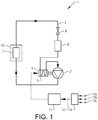
- Fig. 1 illustrates a heat pump system 1.
- the heat pump system comprises a compressor 2 for compressing a working fluid 3 of the heat pump system, an electric motor 4 for providing an output torque for driving the compressor 2 and a means 5 for recovering heat emitted from the electric motor 4 by heating the working fluid 3.
- the compressor 2 has to operate at different compressor speeds. The requested speed is provided by controlling the electric motor 4 driving the compressor 2. At each speed, a certain torque will be required. Thus, in order to maintain the requested compressor speed, the electric motor has to provide a torque determined by the load from the compressor.
- the electric motor can be of the type PMSM (Permanent Magnet Synchronous Motor) or BLDC (Brushless DC motor).
- the heat pump system 1 further comprises an evaporator 6 where the working fluid 3 is heated by heat from the surrounding, a condenser 7 where heat is transferred from the working fluid to the surrounding, and a pressure lowering device 8 such as an expansion valve for lowering the pressure of the working fluid 3.
- the operating principle of the heat pump system can be as follows.
- the working fluid 3 being in gaseous state is pressurized and circulated through the system by the compressor 2.
- the hot and highly pressurized working fluid 3 is cooled in the condenser 7, which is a heat exchanger, until the working fluid 3 condenses into a high-pressure liquid having a lower temperature.
- the condensed working fluid 3 then passes through the pressure-lowering device 8.
- the low-pressure working fluid then enters the evaporator 6, which is another heat exchanger, where the working fluid 3 absorbs heat and is evaporated. Thereafter, the working fluid 3 returns to the compressor 2 and the cycle is repeated.
- the working fluid 3 will also pass close to the electric motor 4 by means of the heat recovering means 5 before entering the compressor 2.
- the heat recovering means 5 is suitably some kind of heat exchanger for transferring heat from the electric motor 4 to the working fluid 3.
- the working fluid 3 functions as a coolant for the electric motor 4 driving the compressor 2.
- the compressor 2 can be cooled by the working fluid 3 for transferring friction heat from the compressor to the working fluid.
- any heat emitted from power electronics associated with the electric motor 4 can be transferred to the working fluid 3.
- the condenser 7 transfers heat to the passenger compartment and/or to any other component such as batteries of the vehicle.
- the passenger compartment 16 is schematically indicated in Fig. 1 .
- the heat transfer can be performed directly, i.e. from the working fluid 3 to air, or indirectly via another working medium.
- the working fluid circulating in the heat pump system 1 can be any suitable medium, such as for example R-134a, R-1234YF or R-744.
- FIG. 2 another variant of the heat pump system 10 is shown.
- This heat pump system 10 can also be used in an electric vehicle application.
- heating mode i.e. when heating the passenger compartment 160 of a vehicle
- a first circuit 150 of the heat pump system 10 interacts with another second circuit 110 having a heater core 120 for heating the passenger compartment 160 as schematically illustrated in Fig. 2 .
- the heater core 120 is arranged in the second circuit 110, which could constitute a sub circuit also for heating batteries (not illustrated) of the vehicle, for instance.
- the working fluid of the second circuit can be water and is circulated by means of a pump 130 and heat is transferred to the passenger compartment 160 of the vehicle by means of the heater core 120.
- an evaporator 70 in the heat pump system 10 is used for transferring heat from the surrounding to the working fluid 30 of the heat pump system and by means of a condenser 140 heat can be transferred from the first circuit 150 to the second circuit 110 provided with the heater core 120.
- the evaporator 70 is suitably a combined evaporator-condenser device that can work as condenser when an evaporator 60 is used for lowering the temperature of the passenger compartment 160 in a cooling mode or AC mode.
- the working fluid 30 is then circulated in a way by-passing the evaporator 60. This can be performed with a first valve 180, a shut off valve for instance, being in an opened state. Further, the working fluid is circulated via a first pressure lowering device 80a arranged in the first circuit 150 between the condenser 140 and the evaporator 70.
- the working fluid 30 can be circulated in a way by-passing the first pressure lowering device 80a. This can be performed with a second valve 190, a shut off valve for instance, being in an opened state, whereas the first shut off valve 180 is closed for circulating the working fluid via a second pressure lowering device 80b and the evaporator 60.
- the working fluid 30 in the heat pump system illustrated in Fig. 2 will also pass close to the electric motor 40 driving the compressor 20 by means of the heat recovering means 50 before entering the compressor 20.
- the heat recovering means 50 is suitably some kind of heat exchanger for transferring heat from the electric motor to the working fluid 30.
- the working fluid 30 of the heat pump system functions as a coolant for the electric motor 40 driving the compressor 20.
- Fig. 3 one example embodiment of the method according to the invention is schematically illustrated in a flow chart.
- the method comprises the steps of providing a first control mode and a second control mode for the electric motor, and controlling the electrical motor in a way creating higher heat losses of the electric motor for a given output torque of the electric motor in the second control mode than in the first control mode, and recovering heat emitted from the electric motor by heating the working fluid.
- control mode is automatically selected by means of a control unit on the basis of receiving a control signal.
- a first step 100 the electric motor is driven in the first control mode by a default setting.
- MTPA Maximum Torque Per Ampere.
- vector control will give the highest efficiency. For example, a field-oriented control (FOC) and a proportional-integral (PI) controller can be used.
- FOC field-oriented control
- PI proportional-integral
- the electric motor is controlled according to the second control mode upon receiving a control signal 12 indicating that a predetermined condition is fulfilled.
- This condition can be for example a heating capacity demand on the heat pump system exceeding a threshold value.
- This threshold value can preferably correspond to the maximum heating capacity of the heat pump system when the electric motor is controlled according to the first control mode.
- this threshold value may vary for different operation conditions and applications.
- the control signal can be based on measurements of one or more physical quantities and any calculations required.
- a control signal based on temperature measurements can be provided for indicating that the heating capacity of the heat pump system is not sufficient and that the control of the electric motor has to be switched to the second control mode.
- the heating capacity of the heat pump system may be fulfilled or not, or even be irrelevant, but still there is a need of increasing the temperature of the working fluid.
- Such additional heating of the working fluid can be required when starting up the system for avoiding liquid compression in the compressor or for defrosting the evaporator of the heat pump system.
- the electric motor can be controlled according to the second control mode upon receiving said control signal indicating an amount of the working fluid, to be entered into the compressor, being in liquid state exceeding a threshold value.
- Such indication can be provided by said control signal indicating a temperature of the working fluid and/or pressure of the working fluid below a threshold value.
- the temperature and/or the pressure of the working fluid can be used for indicating any risk of liquid compression in the compressor.
- the ambient temperature can be measured, since at least when the system is to be started the relationship between these temperatures is known. Only given as an example, for an ambient temperature below -5 °C, the second control mode could be used. Furthermore, only given as an example, for a pressure of the working fluid below 2.5 bar, the second control mode could be used.
- a second step 200 it is checked if such a predetermined condition is fulfilled. If "YES”, i.e. there is such a predetermined condition motivating the second control mode to be applied, then in a third step 300 the control of the electric motor is performed in accordance with the second control mode. Otherwise, if "NO", the first control mode is applied in the first step 100 until such a predetermined condition is fulfilled.
- a fourth step 400 it is checked if the predetermined condition is still fulfilled. If “YES”, the second control mode is applied in the third step 300 until the predetermined condition has ceased, whereas if "NO", the first control mode is applied in the first step 100 until such a predetermined condition is fulfilled again.
- other conditions requiring the first control mode to be applied or the second mode to be ended can be used for overriding any predetermined condition discussed hereinabove and bringing the control strategy back to the first control mode. For example, in case the cooling of the electric motor is not sufficient the second control mode may not be allowed.
- the electric motor In the second control mode, the electric motor is driven to give lower efficiency than in the first control mode, and instead produce more heat for heating the working fluid.
- the electric motor In order to increase the heat emitted from the electric motor, the electric motor is suitably controlled in a way resulting in a higher stator current for a given output torque of the electric motor in the second control mode than in the first control mode.
- the electric motor is preferably controlled in a way creating higher heat losses of stator windings of the electric motor for a given output torque of the electric motor in the second control mode than in the first control mode. Since the heat emitted from the stator windings increases with the stator current in square, an increased stator current will have considerably impact on the heat creating capacity.
- a stator current space vector can be defined in a rotating and time invariant (d, q) coordinate system. As illustrated in the upper half of the coordinate system, the torque is constant along one and the same line, where the torque line intersecting the q-axis at largest distance from the origin of the coordinate system represents the largest torque.
- the vector component along the q-axis is the torque producing component of the stator current
- the vector component along the d-axis is the magnetic flux linkage component of the stator current
- the circle 600 indicated with dotted lines in Fig. 4 shows the maximum stator current for different stator current space vectors.
- the point in the upper half of the coordinate system where the circle 600 and the line 500 intersect gives the largest output torque of the electric motor.
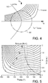
- FIG. 5 Another representation in a stationary coordinate system is shown as an example in Fig. 5 .
- the torque is shown as a function of the stator current Is and the stator current angle Theta.
- the stator current angle Theta is the angle by which the stator current is leading the stator magnetic flux.
- In generator mode Theta is the angle by which the current is lagging relative to the magnetic flux.
- the stator current Is is given in parts of the rated current that can be handled by the electric motor/compression system during continuous operation, i.e. 1 p.u. represents the rated current.
- Figure 5 indicates that the electric motor can continuously supply approximately 21 Nm at 1 p.u.
- a dashed line 700 in Fig. 5 indicates the minimum current required for different torques. If for example the compressor torque request is 10 Nm, it is possible to provide this torque using stator current Is of 0.5 p.u. at Theta ⁇ 114 degrees. This operation is suitably used in the first control mode. In the second control mode Theta is changed for creating increased heat losses. For example, by using 1.0 p.u. current at Theta ⁇ 163 degrees, the torque requirement of 10 Nm is still fulfilled. This motor operating point gives however rise to 4 times the resistive losses compared to most efficient point at the MTPA line.
- stator currents above rated current may be used.
- the electric motor is preferably controlled with a first stator current angle in the first control mode and with a second stator current angle in the second control mode, for a given output torque of the electric motor, where the second stator current angle requires a higher stator current than the first stator current angle.
- the control of the electric motor has to be adapted accordingly.
- the stator current Is2 used in the second control mode is preferably in the range 1,1-10 times the stator current Is1 in the first control mode, preferably 1,2-8 times Is1, and often Is2 is 1,5-2 times Is1.
- both an increased and decreased stator current angle relative to the stator current angle in the first control mode can be used.
- the second stator current angle deviate from the first stator current angle by at least ⁇ 10 degrees, preferably at least ⁇ 15 degrees, and often the difference between the stator current angle Theta2 in the second control mode and the stator current angle Theta1 in the first control mode is within the range 15-50 degrees.
- a stator current angle Theta2 in the second control mode can be in the range 1,1-2 times Theta1, preferably Theta2 is 1,2-1,8 times Theta1.
- the electric motor can be controlled in a way creating higher heat losses of a stator core of the electric motor for a given output torque of the electric motor in the second control mode than in the first control mode. This can be performed by controlling the electric motor with a stator current having a substantially sinusoidal periodic waveform in the first control mode, and with a stator current having a non-sinusoidal periodic waveform in the second control mode.
- the electric motor is preferably controlled with the stator current having a substantially square waveform in the second mode.
- a control unit 11 for controlling the heat pump system is provided.
- the control unit is suitably connected to the power electronics of the electric motor for controlling the electric motor.
- the control unit may comprise one or more microprocessors and/or one or more memory devices or any other components for executing computer programs to perform the method.
- the control unit is preferably provided with a computer program for performing all steps of any embodiment of the method described hereinabove.
- the control unit can be part of a controller used also for other functions of the heat pump system and/or any other function of a vehicle or be provided as a separate unit.
- control unit is configured to provide a first control mode and a second control mode for the electric motor, and configured to control the electric motor in a way creating higher heat losses of the electric motor for a given output torque of the electric motor in the second control mode than in the first control mode.
- the control unit 11 is suitably configured to control the electric motor according to the second control mode upon receiving a control signal 12 indicating that a predetermined condition is fulfilled.
- a control signal can be based on one or more input signals 13a, 13b, 13c from sensors and any calculations required.
- a unit 14 for comparison and/or calculation of the input signals is arranged to produce the control signal 12.
- This unit 14 is depicted outside the control unit 11 but could of course be an integrated part of the control unit 11.
- the input signals 13a, 13b, 13c can be based on measurements of one or more physical quantities related to the heat pump system or other components of a vehicle or the surrounding to the heat pump system/vehicle.
Landscapes
- Engineering & Computer Science (AREA)
- Physics & Mathematics (AREA)
- Mechanical Engineering (AREA)
- Thermal Sciences (AREA)
- General Engineering & Computer Science (AREA)
- Chemical & Material Sciences (AREA)
- Combustion & Propulsion (AREA)
- Air-Conditioning For Vehicles (AREA)
Priority Applications (4)
| Application Number | Priority Date | Filing Date | Title |
|---|---|---|---|
| EP17179286.4A EP3425307A1 (de) | 2017-07-03 | 2017-07-03 | Verfahren zur steuerung eines wärmepumpensystems |
| CN201880042197.1A CN110785618B (zh) | 2017-07-03 | 2018-05-14 | 用于控制热泵系统的方法 |
| PCT/CN2018/086728 WO2019007150A1 (en) | 2017-07-03 | 2018-05-14 | METHOD FOR CONTROLLING A HEAT PUMP SYSTEM |
| US16/706,299 US11384968B2 (en) | 2017-07-03 | 2019-12-06 | Method for controlling a heat pump system |
Applications Claiming Priority (1)
| Application Number | Priority Date | Filing Date | Title |
|---|---|---|---|
| EP17179286.4A EP3425307A1 (de) | 2017-07-03 | 2017-07-03 | Verfahren zur steuerung eines wärmepumpensystems |
Publications (1)
| Publication Number | Publication Date |
|---|---|
| EP3425307A1 true EP3425307A1 (de) | 2019-01-09 |
Family
ID=59298249
Family Applications (1)
| Application Number | Title | Priority Date | Filing Date |
|---|---|---|---|
| EP17179286.4A Pending EP3425307A1 (de) | 2017-07-03 | 2017-07-03 | Verfahren zur steuerung eines wärmepumpensystems |
Country Status (4)
| Country | Link |
|---|---|
| US (1) | US11384968B2 (de) |
| EP (1) | EP3425307A1 (de) |
| CN (1) | CN110785618B (de) |
| WO (1) | WO2019007150A1 (de) |
Cited By (4)
| Publication number | Priority date | Publication date | Assignee | Title |
|---|---|---|---|---|
| DE102018114786A1 (de) * | 2018-06-20 | 2019-12-24 | Stiebel Eltron Gmbh & Co. Kg | Verfahren zum Betrieb einer Wärmepumpe und eine Kältemaschine |
| WO2020198597A1 (en) * | 2019-03-28 | 2020-10-01 | Johnson Controls Technology Company | A heating, ventilation, air conditioning and/or refrigeration system with a compressor motor cooling system |
| US20210101448A1 (en) * | 2019-10-03 | 2021-04-08 | Toyota Jidosha Kabushiki Kaisha | Vehicle-mounted temperature controller |
| DE102020127303A1 (de) | 2020-10-16 | 2022-04-21 | Audi Aktiengesellschaft | Kältemittelverdichter, Kraftfahrzeug und Verfahren zum Betreiben eines Kältemittelverdichters |
Families Citing this family (1)
| Publication number | Priority date | Publication date | Assignee | Title |
|---|---|---|---|---|
| BR102018071557A2 (pt) * | 2018-10-19 | 2020-04-28 | Tecumseh Do Brasil Ltda | método para aumento da eficiência de compressores herméticos aplicados em refrigeração e condicionadores de ar. |
Citations (3)
| Publication number | Priority date | Publication date | Assignee | Title |
|---|---|---|---|---|
| WO2014200476A1 (en) * | 2013-06-12 | 2014-12-18 | Danfoss Turbocor Compressors B.V. | Compressor with rotor cooling passageway |
| DE102013225450B3 (de) * | 2013-12-10 | 2015-03-26 | Robert Bosch Gmbh | Wärmepumpe mit einem kältemittelgekühlten Inverter |
| WO2016170578A1 (ja) * | 2015-04-20 | 2016-10-27 | 三菱電機株式会社 | 冷凍サイクル装置 |
Family Cites Families (12)
| Publication number | Priority date | Publication date | Assignee | Title |
|---|---|---|---|---|
| JP2831706B2 (ja) * | 1989-07-10 | 1998-12-02 | 株式会社東芝 | 空気調和装置 |
| JP3555549B2 (ja) * | 2000-03-31 | 2004-08-18 | ダイキン工業株式会社 | 高圧ドーム型圧縮機 |
| JP2007221850A (ja) * | 2006-02-14 | 2007-08-30 | Matsushita Electric Ind Co Ltd | 三相電動機の位相切換え装置 |
| JP2008104337A (ja) * | 2006-09-21 | 2008-05-01 | Sanyo Electric Co Ltd | 冷媒圧縮機用電動機の制御装置 |
| US8726661B2 (en) * | 2010-08-09 | 2014-05-20 | GM Global Technology Operations LLC | Hybrid powertrain system including an internal combustion engine and a stirling engine |
| US20120253735A1 (en) * | 2011-03-29 | 2012-10-04 | Searete Llc | Method and apparatus for operating a motor with optimized efficiency |
| GB2526741A (en) * | 2013-03-15 | 2015-12-02 | Trane Int Inc | Apparatuses, systems, and methods of variable frequency drive operation and control |
| JP5950865B2 (ja) * | 2013-05-14 | 2016-07-13 | ジョンソンコントロールズ ヒタチ エア コンディショニング テクノロジー(ホンコン)リミテッド | 電動機及びこれを用いた空気調和機 |
| CN105371544A (zh) * | 2014-08-29 | 2016-03-02 | 青岛海尔洗衣机有限公司 | 一种热泵系统及其控制方法和干衣机 |
| JP6071972B2 (ja) * | 2014-10-07 | 2017-02-01 | 三菱電機株式会社 | 空気調和機 |
| CN104596171B (zh) * | 2014-12-22 | 2018-03-09 | 广东美的制冷设备有限公司 | 空调器及空调器中压缩机电机的控制方法和控制装置 |
| CN104654527A (zh) * | 2015-02-04 | 2015-05-27 | 广东美芝制冷设备有限公司 | 空调器及空调器中压缩机的控制系统和方法 |
-
2017
- 2017-07-03 EP EP17179286.4A patent/EP3425307A1/de active Pending
-
2018
- 2018-05-14 WO PCT/CN2018/086728 patent/WO2019007150A1/en active Application Filing
- 2018-05-14 CN CN201880042197.1A patent/CN110785618B/zh active Active
-
2019
- 2019-12-06 US US16/706,299 patent/US11384968B2/en active Active
Patent Citations (3)
| Publication number | Priority date | Publication date | Assignee | Title |
|---|---|---|---|---|
| WO2014200476A1 (en) * | 2013-06-12 | 2014-12-18 | Danfoss Turbocor Compressors B.V. | Compressor with rotor cooling passageway |
| DE102013225450B3 (de) * | 2013-12-10 | 2015-03-26 | Robert Bosch Gmbh | Wärmepumpe mit einem kältemittelgekühlten Inverter |
| WO2016170578A1 (ja) * | 2015-04-20 | 2016-10-27 | 三菱電機株式会社 | 冷凍サイクル装置 |
Cited By (8)
| Publication number | Priority date | Publication date | Assignee | Title |
|---|---|---|---|---|
| DE102018114786A1 (de) * | 2018-06-20 | 2019-12-24 | Stiebel Eltron Gmbh & Co. Kg | Verfahren zum Betrieb einer Wärmepumpe und eine Kältemaschine |
| WO2020198597A1 (en) * | 2019-03-28 | 2020-10-01 | Johnson Controls Technology Company | A heating, ventilation, air conditioning and/or refrigeration system with a compressor motor cooling system |
| CN113785165A (zh) * | 2019-03-28 | 2021-12-10 | 江森自控泰科知识产权控股有限责任合伙公司 | 具有压缩机马达冷却系统的加热、通风、空调、和/或制冷系统 |
| CN113785165B (zh) * | 2019-03-28 | 2023-05-05 | 江森自控泰科知识产权控股有限责任合伙公司 | 具有压缩机马达冷却系统的加热、通风、空调、和/或制冷系统 |
| US20210101448A1 (en) * | 2019-10-03 | 2021-04-08 | Toyota Jidosha Kabushiki Kaisha | Vehicle-mounted temperature controller |
| US11951806B2 (en) * | 2019-10-03 | 2024-04-09 | Toyota Jidosha Kabushiki Kaisha | Vehicle-mounted temperature controller |
| DE102020127303A1 (de) | 2020-10-16 | 2022-04-21 | Audi Aktiengesellschaft | Kältemittelverdichter, Kraftfahrzeug und Verfahren zum Betreiben eines Kältemittelverdichters |
| DE102020127303B4 (de) | 2020-10-16 | 2024-03-28 | Audi Aktiengesellschaft | Kältemittelverdichter, Kraftfahrzeug und Verfahren zum Betreiben eines Kältemittelverdichters |
Also Published As
| Publication number | Publication date |
|---|---|
| US11384968B2 (en) | 2022-07-12 |
| US20200116399A1 (en) | 2020-04-16 |
| WO2019007150A1 (en) | 2019-01-10 |
| CN110785618B (zh) | 2021-12-31 |
| CN110785618A (zh) | 2020-02-11 |
Similar Documents
| Publication | Publication Date | Title |
|---|---|---|
| US11384968B2 (en) | Method for controlling a heat pump system | |
| US20080072619A1 (en) | Control device of motor for refrigerant compressor | |
| EP1764566A1 (de) | Wärmepumpenvorrichtung | |
| CN111347939B (zh) | 车辆及其动力电池温度控制装置 | |
| JP5805317B2 (ja) | ヒートポンプ装置、空気調和機および冷凍機 | |
| CN111347928B (zh) | 车辆及其动力电池温度控制装置 | |
| JP2016001062A (ja) | インバータ制御装置 | |
| JPWO2016051456A1 (ja) | 巻線切替モータ駆動装置、巻線切替モータの駆動制御方法、及びそれらを用いた冷凍空調機器 | |
| JP3943124B2 (ja) | ヒートポンプ応用機器 | |
| JP5561206B2 (ja) | バッテリの充電制御装置 | |
| US20140230463A1 (en) | Method for controlling a compressor of a thermal storage heat pump system | |
| US10634390B2 (en) | Electric compressor | |
| CN100576719C (zh) | 冷媒压缩机用电动机的控制装置 | |
| US11437945B2 (en) | Motor-driven compressor | |
| JP6286669B2 (ja) | インバータ制御装置 | |
| US20230251014A1 (en) | Refrigerating and air-conditioning apparatus | |
| WO2022176148A1 (ja) | 冷凍サイクル装置 | |
| CN113432246B (zh) | 一种空调器除霜控制方法及装置、空调器 | |
| CN109564032B (zh) | 热泵装置、空气调节机及热水器 | |
| CN115899962A (zh) | 一种空调器及其风机转速控制方法 | |
| JP2020110021A (ja) | モータ制御システム |
Legal Events
| Date | Code | Title | Description |
|---|---|---|---|
| PUAI | Public reference made under article 153(3) epc to a published international application that has entered the european phase |
Free format text: ORIGINAL CODE: 0009012 |
|
| STAA | Information on the status of an ep patent application or granted ep patent |
Free format text: STATUS: REQUEST FOR EXAMINATION WAS MADE |
|
| 17P | Request for examination filed |
Effective date: 20170703 |
|
| AK | Designated contracting states |
Kind code of ref document: A1 Designated state(s): AL AT BE BG CH CY CZ DE DK EE ES FI FR GB GR HR HU IE IS IT LI LT LU LV MC MK MT NL NO PL PT RO RS SE SI SK SM TR |
|
| AX | Request for extension of the european patent |
Extension state: BA ME |
|
| STAA | Information on the status of an ep patent application or granted ep patent |
Free format text: STATUS: EXAMINATION IS IN PROGRESS |
|
| 17Q | First examination report despatched |
Effective date: 20200430 |
|
| STAA | Information on the status of an ep patent application or granted ep patent |
Free format text: STATUS: EXAMINATION IS IN PROGRESS |
|
| STAA | Information on the status of an ep patent application or granted ep patent |
Free format text: STATUS: EXAMINATION IS IN PROGRESS |
|
| REG | Reference to a national code |
Ref country code: DE Ref legal event code: R079 Free format text: PREVIOUS MAIN CLASS: F25B0025000000 Ipc: F25B0041390000 |
|
| GRAP | Despatch of communication of intention to grant a patent |
Free format text: ORIGINAL CODE: EPIDOSNIGR1 |
|
| STAA | Information on the status of an ep patent application or granted ep patent |
Free format text: STATUS: GRANT OF PATENT IS INTENDED |
|
| RIC1 | Information provided on ipc code assigned before grant |
Ipc: F25B 49/02 20060101ALI20240208BHEP Ipc: F25B 40/06 20060101ALI20240208BHEP Ipc: F25B 25/00 20060101ALI20240208BHEP Ipc: F25B 41/39 20210101AFI20240208BHEP |
|
| INTG | Intention to grant announced |
Effective date: 20240304 |
|
| RAP3 | Party data changed (applicant data changed or rights of an application transferred) |
Owner name: NINGBO GEELY AUTOMOBILE RESEARCH & DEVELOPMENT CO. LTD. |