EP3424869B1 - System for stabilizing self-propelled operating machines - Google Patents
System for stabilizing self-propelled operating machines Download PDFInfo
- Publication number
- EP3424869B1 EP3424869B1 EP18180124.2A EP18180124A EP3424869B1 EP 3424869 B1 EP3424869 B1 EP 3424869B1 EP 18180124 A EP18180124 A EP 18180124A EP 3424869 B1 EP3424869 B1 EP 3424869B1
- Authority
- EP
- European Patent Office
- Prior art keywords
- arms
- raised position
- segment
- stabilizers
- completely
- Prior art date
- Legal status (The legal status is an assumption and is not a legal conclusion. Google has not performed a legal analysis and makes no representation as to the accuracy of the status listed.)
- Active
Links
Images


Classifications
-
- B—PERFORMING OPERATIONS; TRANSPORTING
- B66—HOISTING; LIFTING; HAULING
- B66F—HOISTING, LIFTING, HAULING OR PUSHING, NOT OTHERWISE PROVIDED FOR, e.g. DEVICES WHICH APPLY A LIFTING OR PUSHING FORCE DIRECTLY TO THE SURFACE OF A LOAD
- B66F9/00—Devices for lifting or lowering bulky or heavy goods for loading or unloading purposes
- B66F9/06—Devices for lifting or lowering bulky or heavy goods for loading or unloading purposes movable, with their loads, on wheels or the like, e.g. fork-lift trucks
- B66F9/075—Constructional features or details
- B66F9/07559—Stabilizing means
-
- B—PERFORMING OPERATIONS; TRANSPORTING
- B66—HOISTING; LIFTING; HAULING
- B66C—CRANES; LOAD-ENGAGING ELEMENTS OR DEVICES FOR CRANES, CAPSTANS, WINCHES, OR TACKLES
- B66C23/00—Cranes comprising essentially a beam, boom, or triangular structure acting as a cantilever and mounted for translatory of swinging movements in vertical or horizontal planes or a combination of such movements, e.g. jib-cranes, derricks, tower cranes
- B66C23/62—Constructional features or details
- B66C23/72—Counterweights or supports for balancing lifting couples
- B66C23/78—Supports, e.g. outriggers, for mobile cranes
- B66C23/80—Supports, e.g. outriggers, for mobile cranes hydraulically actuated
-
- B—PERFORMING OPERATIONS; TRANSPORTING
- B66—HOISTING; LIFTING; HAULING
- B66F—HOISTING, LIFTING, HAULING OR PUSHING, NOT OTHERWISE PROVIDED FOR, e.g. DEVICES WHICH APPLY A LIFTING OR PUSHING FORCE DIRECTLY TO THE SURFACE OF A LOAD
- B66F9/00—Devices for lifting or lowering bulky or heavy goods for loading or unloading purposes
- B66F9/06—Devices for lifting or lowering bulky or heavy goods for loading or unloading purposes movable, with their loads, on wheels or the like, e.g. fork-lift trucks
- B66F9/065—Devices for lifting or lowering bulky or heavy goods for loading or unloading purposes movable, with their loads, on wheels or the like, e.g. fork-lift trucks non-masted
- B66F9/0655—Devices for lifting or lowering bulky or heavy goods for loading or unloading purposes movable, with their loads, on wheels or the like, e.g. fork-lift trucks non-masted with a telescopic boom
Definitions
- This invention relates to a system for stabilizing self-propelled operating machines, in particular telescopic handlers or "telehandlers”.
- telescopic handlers consisting of a vehicle equipped with a movable frame on wheels, which comprises a platform mounted on the frame, which in turn mounts the driver's cab and an operating arm which can be extended telescopically.
- an apparatus for lifting or moving loads such as, for example, a fork, a cage, a lateral transfer unit, a hoist, etc.
- Each stabilizing unit comprises a pair of arms rotatable and extendable telescopically, usually with a single sliding member, which have respective distal ends, designed to be rested on the ground by means of supporting feet, and proximal ends, hinged to a supporting frame.
- the stabilizing arms are positioned crossed relative to each other and, during the lifting, move like a pair of scissors.
- the stabilizers are moved to the non-operating configuration in which they have the minimum overall dimensions, thus lowering the machine until resting the wheels on the ground.
- the sliding members of the arms are partially retracted into the respective first segments until the wheels rest on the ground.
- the arms are rotated upwards in such a way as to be horizontal, parallel to each other; the sliding members are retracted completely only after the arms have reached the horizontal position, concluding the operations for recovery and enabling the operator to start the vehicle drive.
- the technical purpose which forms the basis of this invention is to propose a system for stabilizing self-propelled operating machines and a method for controlling stabilizing, which satisfy the above-mentioned need.
- the aim specified is achieved by a method implemented according to claim 1 and by a system made according to claim 13.
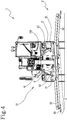
- the numeral 1 denotes in its entirety a vehicle comprising the system according to the invention.
- the system proposed has been especially conceived for implementation on a vehicle 1 consisting of a self-propelled operating machine such as a telehandler or an aerial platform, etc... and my be of the rotary type or even of the fixed type.
- the system according to the invention includes stabilizers 10 designed to be mounted on the vehicle 1 and equipped with a plurality of stabilizing arms 2.
- the stabilizers 10 provided in the system according to the invention are of the so-called “scissor” or "X” type, and include two pairs of telescopic arms 2, for example with a single sliding member, located at the front and at the rear of the vehicle 1, in the proximity of the wheels 11.
- the stabilizers 10 include a supporting structure 100, fixed to or incorporated in the frame of the machine 1, to which the arms 2 of a pair are individually hinged, in a cross configuration, so as to be able to move in a counter-rotating fashion, like a pair of scissors.
- the two arms 2 connected to the same supporting structure 100 are mounted one in front of the other, so as to move in parallel planes, generically vertical.
- the stabilizers 10 of the system proposed are designed to pass from operating configurations, wherein they stabilize the machine 1, raising the wheels above the ground, to a rest configuration, in which the wheels 11 are returned to the ground, and vice versa.
- the stabilizing arms 2 are movable between a raised position, wherein they are distanced from the ground (see Figure 6 ), and in particular freely allow the driving of the vehicle 1, and at least one lowered operating position ( Figures 1 and 2 ), wherein they are rested on the ground to initiate the stabilization.
- the working position or position for resting the arms 2 is that of contact which starts the lifting thrust.
- the arms 2 may rest on the ground with variable inclinations and lengths.
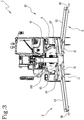
- the arms 2 include a first segment 21, or “sleeve”, which is hollow and in which is contained in a slidable fashion a second segment 22, or “sliding member”, which is equipped, at the distal end, with a supporting element, that is, the above-mentioned foot 20.
- each segment 21, 22 may comprise a rectilinear beam, which is hollow and with a quadrangular cross section.
- the beam of the second segment 22 is inserted with the possibility of sliding in the beam of the first segment 21, which will obviously have a larger cross-section.
- the invention comprises first movement designed to individually rotate the arms 2 between a completely raised position and lowered working positions.
- the first movement means comprise a hydraulic cylinder 3 for each arm 2.
- first segment 21 of each arm 2 is connected to the supporting structure 100 by a first hinge 43; moreover, at the end of the movement of the arm 2 about the first hinge 43, use is made of the hydraulic cylinder 3, the thrust of which is used for lifting during the stabilizing step.
- Each cylinder 3 is connected by a second hinge 41 to the supporting structure 100 and, through a third hinge 42, to the first segment 21 of the respective arm 2.
- the first and the third hinge 42, 43 are positioned in two distinct points of the length of the sleeve 21, preferably at the upper side, the first being further inside, that is closer to the proximal end of the first segment 21, and the third further outside, that is, closer to the distal end.
- the hydraulic cylinders 5 are actuated with a pushing action to move the arms 2 to the ground and raise the vehicle 1, whilst they are actuated with a retraction action when the vehicle 1 is returned to rest on the wheels and the arms 2 are raised in the rest position.
- the invention includes second movement means, for example comprising hydraulic cylinders (not shown), designed to move individually the second segments 22 between a completely closed position and extended positions.
- the system according to the invention includes a processing unit, designed for adjusting the movements of the stabilizers 10, as described in more detail below.
- processing unit is presented as divided into separate functional modules for the purpose of describing the functions clearly and completely.
- the processing unit may consist of a single electronic device, also of the type commonly present on this type of machine, suitably programmed to perform the functions described; the various modules can correspond to hardware units and/or software forming part of the programmed device.
- the functions can be performed by a plurality of electronic devices on which the above-mentioned functional modules can be distributed.
- the processing unit may have one or more microprocessors for execution of the instructions contained in the memory modules and the above-mentioned functional modules may also be distributed on a plurality of local or remote calculators based on the architecture of the network on which they are housed.
- the processing unit is configured to control the above-mentioned first and second movement means in such a way that the stabilizers 10 carry out the following retraction sequence, starting from a working configuration in which the machine is stabilized (see Figure 2 ):
- the rotation of the arms 2 to the first partial position is achieved by initially rotating the arms 2 up to a second partially raised position, lower than the first position, where the wheels of the machine are rested, and the rotation then continues up to the above-mentioned first position.
- the feet In the second partially raised position, the feet can still be in contact with the ground.
- the arms 2 are substantially horizontal and parallel to each other, whilst in the partially raised position they are crossed.
- the arms 2 of both the pairs move together, even though this does not exclude solutions in which the arms 2 can have off-set movements, providing the above-mentioned sequence is complied with.
- the invention comprises a retraction sequence of the stabilizer 10 which is significantly different from that used with the prior art systems.
- the invention comprises a sequence of retraction wherein the second segments move to their position of minimum length, therefore with complete retraction, when the arms 2 are still in a partial retraction position; only after the sliding members are retracted do the arms 2 complete the rotation upwards to the final position of rest.
- the arms 2 are still crossed and oblique relative to a horizontal reference plane, which, for example, can be identified as the plane passing through the four first hinges of the four stabilizing arms mounted on the operating machine. More generally speaking, in the first partially raised position, the arms 2 are set at an angle A different from zero relative to an ideal plane P integral to the supporting structure 100 mentioned several times above (see Figure 5 ).
- the ideal plane P is generically "horizontal” or it can be defined as a plane in which the second segments of the arms 2 lie in their completely raised position, or a plane parallel to them.
- the above-mentioned angle A is equal to 4°, although, as will be explained in more detail below, the invention can operate perfectly even with a different inclination.
- the invention allows an improvement in efficiency of use of the self-propelled operating machine.
- the processing unit is connected to the commands located in the cabin of the machine, in such a way that the operator can operate the stabilizers 10 by means of a joystick or other commands.
- the stabilizing arms perform the retraction sequence predetermined by the processing unit; in this case, the operator can interrupt the sequence, for safety reasons, simply by releasing the command.
- the sequence of movements of the arms 2 may be fully automatic and be initialised by pressing a pushbutton, or by using a touch screen display or by using a voice command, etc.
- the proposed system preferably comprises the use of an electro-hydraulic distributor which controls the above-mentioned cylinders 5 that move the arms 2 in rotation and elongation (or retraction).
- the distributor is designed to adjust the operation of the cylinders 5 of the stabilizers 10, as a function of control signals arriving from the processing unit.
- the control signals are produced in a sequence predetermined by the processing unit and are designed to move the hydraulic cylinders in the stabilizing arms 2 in such a way as to perform the retraction sequence described above.
- the invention may include first detecting means 51, 52, connected to the processing unit and designed to measure the inclination of the arms 2 relative to the above-mentioned reference plane P.
- the invention may include second detecting means (not illustrated), connected to the processing unit and designed to measure the length of the part of second segment 22 that is projecting with respect to the respective first segment 21.
- the first detecting means include, for each arm 2, an indicating element 51 integral with it and also comprise one or more control sensors for 52 for detecting the indicating element.
- the indicating element 51 is configured in such a way that its detection by the sensor represents the fact that the respective arm 2 has reached the above-mentioned first partially raised position (shown in Figure 5 ).
- the sensors 52 are designed to produce an inclination signal as a function of the measurements taken, transmitted to the processing unit which controls the hydraulic distributor in accordance with the inclination signals received.
- each indicating element 51 is fixed to the first segment 21 of the respective arm 2 and, for each indicating element 51, there is a proximity sensor 52 mounted on the supporting structure 100, arranged in such a way that its area of detection superposes the path along which the indicating element 51 moves.
- the indicating element may comprise a shaped plate 51, projecting from the upper side of the first segment 21 and having dimensions such that its detection by the relative sensor 52 represents the fact that the arm 2 has reached its partially raised position, for example inclined at 4° relative to the reference plane, so that the processing unit completely retracts the second segment 22 in the first segment 21.
- the indicating element may also be shaped and dimensioned in such a way as to allow checking if the arms 2 are in the above-mentioned completely raised position, in which the retraction is completed.
- the supporting structure 100 comprises, for each indicating element 51, a through hole 101 designed to receive the element 51, formed in its lower wall; in this case, the proximity sensor 52 may be mounted above the upper surface of the wall and positioned in front of the hole 101, to allow detection of the free end of the indicating element 51 which protrudes from the hole 101, during the recovery of the stabilizers 10.
- the first measuring detecting means can comprise a position sensor for each arm 2, mounted on the upper side of the first segment 21 and designed to measure the distance relative to the above-mentioned lower wall of the supporting structure 100 or, vice versa, it may be mounted on the lower surface of the structure and perform the same function.
- the inclination of the arm 2 that is to say, the angle formed by the first segment 21 and the reference plane P, which in this case may also be the plane on which the lower wall of the supporting structure 100 lies, or a plane parallel to it.
- each second segment 22 may comprise a non-extendable cable wound on a reel connected to a sensor, such as, for example, an encoder or other angular position transducer.
- a sensor such as, for example, an encoder or other angular position transducer.
- position sensors may be used which measure the distance of a fixed reference to the second segment 22 relative to the first segment 21 and so on.
- the sensors of the second detecting means are designed to check when the second segments 22 are in the completely closed position (shown in Figures 5 and 6 ) which corresponds to the minimum length of the arms allowed and, consequently, to the condition wherein the stabilizers 10 define the minimum lateral dimensions of the machine 1 on which they are mounted.
- the complete closing position is the position of minimum extension, or maximum retraction, of the second segment 22 and, according to some versions of the invention, may correspond to the condition of a protruding part of the second segment 22 with zero length, with the feet 20 in contact with the distal ends of the first segment 21; in other versions it may, on the other hand, correspond to a condition of the protruding part of the second segment 22 with a minimum length not zero, that is, without contact between the feet 20 and the first segment 21.
- the processing unit comprises an inclination module configured for verifying whether the arms 2 are in the first partially raised position, in which they are inclined with respect to the reference plane by a first retraction angle A, or in the completely raised position, in which they are inclined by a second retraction angle.
- the processing unit is able to establish whether or not and when the arms 2 are in the first partial raising position or in the complete raising position.
- the second retraction angle is zero, which corresponds to the case in which, in the rest configuration of the stabilizers 10, the arms 2 and in particular the first segments are horizontal, therefore parallel to the reference plane P or lying on it.
- the first angle A is greater than zero degrees and can be less than 10°, preferably between 0.1° and 6° and, still more preferably, between 0.1° and 4° and, still more in detail, is substantially equal to 4°.
- the arms 2 are crossed, that is to say, they are not parallel.
- the processing unit may also comprise an extension module, configured for verifying whether the second segments 22 are in the relative completely closed position, in which they have a predetermined retraction length, which may be zero (apart from the foot) or not zero.
- the second segment 22 may be completely inserted in the first segment 21, with the foot 20 which clearly remains outside, or the second segment may protrude from the first by a predetermined length; in both cases, the extension module receives from the sensor of the second detection means a signal whose length represents the completely closed state of the relative second segment 22.
- the processing unit comprises a memory module in which are recorded control parameters as a function of the first angle A, the second angle and the predetermined length.
- the processing unit may include a user interface configured to allow an operator to select or set up the control parameters.
- the operator in the cabin starts the steps for retraction of the stabilizers 10, using a special command.
- the stabilizing arms 2 move in a synchronised fashion and, more specifically, all four simultaneously.
- the arms 2 raise by means of the rotation of the first segments 21 upwards, so that the wheels 11 first touch the ground (condition corresponding to that referred to above as the second partially raised position; Figure 3 ), and then continue until reaching the first partially raised position, determined by the control parameter representing the first above-mentioned angle A ( Figure 4 ).
- the hydraulic cylinders 5 located between the first segments 21 and the supporting structure 100 are actuated in retraction fashion so as to rotate the arms 2 to a position in which the proximity sensors 52 "see” the indicating elements 51.
- the arms 2 are shortened, until the sensors of the second detecting means signal to the processing unit that the second segments 22 have reached the relative completely closed position, determined on the basis of the respective control parameter stored (see Figure 5 ).
- the invention is also configured as a method for controlling scissor-like stabilizers 10 of self-propelled operating machines 1 which can be actuated by means of the system described above.
- the stabilizers 10 are brought to the rest configuration ( Figure 6 ), by means of the following sequence of steps:
- the method according to the invention may comprise steps which correspond to the functions performed by the various components of the proposed stabilizing system.
- the rotation of the arms 2 to the first partial position is achieved by initially rotating the arms 2 to a second partially raised position, lower than the first position, wherein the feet still rest on the ground, thereby allowing the resting of the wheels 11 of the machine 1, after which the arms 2 rotate to the first position.
- the arms 2 are horizontal and parallel to each other whilst in the first partially raised position the arms 2 are crossed relative to each other, with the respective feet 20 distanced from the ground.
- the arms 2 are inclined by a non-zero angle A relative to the completely raised position; the angle may be less than or equal to 10 degrees and more specifically between 0.1 and 6 degrees.
- the angle A of the first partially raised position is between 0.1 and 4 degrees and, still more preferably, is equal to 4°.
- the arms 2 have a minimum length, so that the stabilizers 10 define the minimum lateral dimensions of the machine.
- the arms 2 When they are in the completely raised the arms 2 define a configuration of the stabilizers 10 wherein they have the maximum distance relative to the ground, that is to say, the minimum dimensions in height.
- the invention is configured also as a computer program according to claim 23 which, running on an electronic processing unit, implements the steps of the proposed method.
Landscapes
- Engineering & Computer Science (AREA)
- Structural Engineering (AREA)
- Transportation (AREA)
- Mechanical Engineering (AREA)
- Geology (AREA)
- Life Sciences & Earth Sciences (AREA)
- Civil Engineering (AREA)
- Forklifts And Lifting Vehicles (AREA)
- Vehicle Body Suspensions (AREA)
- Agricultural Machines (AREA)
- Operation Control Of Excavators (AREA)
- Control Of Position, Course, Altitude, Or Attitude Of Moving Bodies (AREA)
- Soil Working Implements (AREA)
- Lifting Devices For Agricultural Implements (AREA)
Priority Applications (5)
| Application Number | Priority Date | Filing Date | Title |
|---|---|---|---|
| RS20200656A RS60409B1 (sr) | 2017-07-07 | 2018-06-27 | Sistem za stabilizaciju samopogonskih operativnih mašina |
| SM20200293T SMT202000293T1 (it) | 2017-07-07 | 2018-06-27 | Sistema per stabilizzare macchine operatrici semoventi |
| PL18180124T PL3424869T3 (pl) | 2017-07-07 | 2018-06-27 | Układ do stabilizacji samobieżnych maszyn roboczych |
| SI201830069T SI3424869T1 (sl) | 2017-07-07 | 2018-06-27 | Sistem za stabilizacijo samovoznih delovnih strojev |
| HRP20200912TT HRP20200912T1 (hr) | 2017-07-07 | 2020-06-08 | Sustav za stabilizaciju samopogonskih operativnih strojeva |
Applications Claiming Priority (1)
| Application Number | Priority Date | Filing Date | Title |
|---|---|---|---|
| IT102017000076727A IT201700076727A1 (it) | 2017-07-07 | 2017-07-07 | Sistema per stabilizzare macchine operatrici semoventi. |
Publications (2)
| Publication Number | Publication Date |
|---|---|
| EP3424869A1 EP3424869A1 (en) | 2019-01-09 |
| EP3424869B1 true EP3424869B1 (en) | 2020-03-18 |
Family
ID=61952759
Family Applications (1)
| Application Number | Title | Priority Date | Filing Date |
|---|---|---|---|
| EP18180124.2A Active EP3424869B1 (en) | 2017-07-07 | 2018-06-27 | System for stabilizing self-propelled operating machines |
Country Status (16)
| Country | Link |
|---|---|
| US (1) | US10752479B2 (it) |
| EP (1) | EP3424869B1 (it) |
| CN (1) | CN109205515B (it) |
| AU (1) | AU2018204919B2 (it) |
| CY (1) | CY1123080T1 (it) |
| DK (1) | DK3424869T3 (it) |
| ES (1) | ES2798308T3 (it) |
| HR (1) | HRP20200912T1 (it) |
| HU (1) | HUE049303T2 (it) |
| IT (1) | IT201700076727A1 (it) |
| LT (1) | LT3424869T (it) |
| PL (1) | PL3424869T3 (it) |
| PT (1) | PT3424869T (it) |
| RS (1) | RS60409B1 (it) |
| SI (1) | SI3424869T1 (it) |
| SM (1) | SMT202000293T1 (it) |
Families Citing this family (27)
| Publication number | Priority date | Publication date | Assignee | Title |
|---|---|---|---|---|
| IT201700008621A1 (it) * | 2017-01-26 | 2018-07-26 | Cnh Ind Italia Spa | Piede di stabilizzazione per braccio di stabilizzazione di una macchina da lavoro |
| IT201700076727A1 (it) * | 2017-07-07 | 2019-01-07 | Manitou Italia Srl | Sistema per stabilizzare macchine operatrici semoventi. |
| DE102018204281A1 (de) * | 2018-03-20 | 2019-09-26 | Putzmeister Engineering Gmbh | Vorrichtung zur Grundbruchüberwachung und System |
| USD1006834S1 (en) | 2018-11-27 | 2023-12-05 | Manitou Italia S.R.L. | Cabin for vehicle |
| CN113382949B (zh) * | 2019-02-14 | 2023-09-05 | 株式会社多田野 | 外伸支腿控制装置 |
| IT201900012297A1 (it) * | 2019-07-18 | 2021-01-18 | Manitou Italia Srl | Telehandler con stabilizzatori perfezionati. |
| IT201900023835A1 (it) * | 2019-12-12 | 2021-06-12 | Manitou Italia Srl | Macchina operatrice con stabilizzatori perfezionati. |
| ZA202110395B (en) | 2020-12-30 | 2023-11-29 | Manitou Italia Srl | Telehandler with facilitated alignment adjustment |
| IT202100006392A1 (it) * | 2021-03-17 | 2022-09-17 | Almac S R L | Macchina stabilizzata |
| USD982043S1 (en) | 2021-04-02 | 2023-03-28 | Manitou Italia S.R.L. | Ballast |
| CA206853S (en) | 2021-04-02 | 2023-07-20 | Manitou Italia Srl | Telescopic handler |
| USD1013586S1 (en) | 2021-04-02 | 2024-02-06 | Manitou Italia S.R.L. | Protective grille for vehicle |
| USD1020812S1 (en) | 2021-11-18 | 2024-04-02 | Manitou Italia S.R.L. | Cabin for telescopic lifter |
| USD1005637S1 (en) | 2021-11-18 | 2023-11-21 | Manitou Italia S.R.L. | Turret for telescopic lifter |
| USD998835S1 (en) | 2021-11-18 | 2023-09-12 | Manitou Italia S.R.L. | Headlight for telescopic lifter |
| USD1026047S1 (en) | 2021-11-19 | 2024-05-07 | Manitou Italia S.R.L. | Visor for telescopic lifter |
| USD1048115S1 (en) | 2021-11-19 | 2024-10-22 | Manitou Italia S.R.L. | Cabin hood for a vehicle with a telescopic lifter |
| USD1060439S1 (en) | 2021-11-19 | 2025-02-04 | Manitou Italia S.R.L. | Console with hand controls for telescopic lifter |
| USD1070223S1 (en) | 2021-12-29 | 2025-04-08 | Manitou Italia S.R.L. | Part of cabin for telescopic lifter |
| USD1063289S1 (en) | 2021-12-29 | 2025-02-18 | Manitou Italia S.R.L. | Ladder for telescopic lifter |
| USD1103224S1 (en) | 2022-02-02 | 2025-11-25 | Manitou Italia S.R.L. | Handles for telescopic lifter |
| USD1086632S1 (en) | 2022-02-08 | 2025-07-29 | Manitou Italia S.R.L. | Cabin hood for a vehicle with a telescopic lifter |
| USD1060923S1 (en) | 2022-02-08 | 2025-02-04 | Manitou Italia S.R.L. | Platform for telescopic lifter |
| USD995578S1 (en) | 2022-02-08 | 2023-08-15 | Manitou Italia S.R.L. | Cabin for telescopic lifter |
| CN116653877B (zh) * | 2023-05-19 | 2026-03-13 | 中科云谷科技有限公司 | 支腿运动调节系统、方法以及工程车辆 |
| ZA202502245B (en) * | 2024-03-19 | 2025-12-17 | Manitou Italia Srl | System for stabilising self-propelled operating machines |
| EP4620891A1 (en) * | 2024-03-19 | 2025-09-24 | Manitou Italia S.r.l. | Stabilising system for self-propelled operating machines |
Family Cites Families (25)
| Publication number | Priority date | Publication date | Assignee | Title |
|---|---|---|---|---|
| US3958813A (en) * | 1975-03-17 | 1976-05-25 | Harnischfeger Corporation | Positive safety locking system for powered outrigger beams |
| US4124226A (en) * | 1977-10-06 | 1978-11-07 | Harnischfeger Corporation | Electrohydraulic outrigger control system |
| FR2418126A1 (fr) * | 1978-02-28 | 1979-09-21 | Poclain Sa | Engin mobile comportant un dispositif de stabilisation |
| DE4407827A1 (de) * | 1994-03-09 | 1995-09-14 | Franz Weber | Transportgerechte klappbare Bewegungselemente + Kranen an Hubbühnen mit ein- und ausrastbarem Fahrwerk |
| US6227569B1 (en) * | 1999-05-13 | 2001-05-08 | Ingersoll-Rand Company | Stabilizer mechanical support linkage |
| US7383906B2 (en) * | 2002-08-29 | 2008-06-10 | Jlg Industries, Inc. | Rotatable and telescopic work machine |
| US6802687B2 (en) * | 2002-12-18 | 2004-10-12 | Caterpillar Inc | Method for controlling a raise/extend function of a work machine |
| JP3999697B2 (ja) * | 2003-04-28 | 2007-10-31 | 株式会社アイチコーポレーション | アウトリガジャッキ |
| US7489098B2 (en) * | 2005-10-05 | 2009-02-10 | Oshkosh Corporation | System for monitoring load and angle for mobile lift device |
| CN100528647C (zh) * | 2007-09-21 | 2009-08-19 | 三一重工股份有限公司 | 一种行走式机械支承装置及具有这种支承装置的混凝土泵车 |
| CN201284200Y (zh) * | 2008-08-21 | 2009-08-05 | 徐州徐工随车起重机有限公司 | 工程机械的“八”字型支腿 |
| CN102431915B (zh) * | 2011-12-09 | 2013-09-04 | 徐州重型机械有限公司 | 一种起重机x型支腿及设有该支腿的起重机 |
| CN202558574U (zh) * | 2012-04-11 | 2012-11-28 | 北京凯博擦窗机械技术公司 | 履带式蜘蛛型高空作业平台 |
| ES2635739T3 (es) * | 2012-10-17 | 2017-10-04 | Iveco Magirus Ag | Vehículo utilitario con sistema de supervisión para supervisar la posición de los estabilizadores |
| ITMO20130087A1 (it) * | 2013-04-05 | 2014-10-06 | C M C S R L Societa Unipersonal E | Carrello sollevatore dotato di mezzi stabilizzatori |
| PT2980002T (pt) * | 2014-07-28 | 2017-08-28 | Manitou Italia Srl | Aparelho de estabilização |
| DK2982639T3 (en) * | 2014-08-04 | 2018-12-17 | Manitou Italia Srl | LATERAL STABILIZATION SYSTEM |
| CN204057788U (zh) * | 2014-08-27 | 2014-12-31 | 湖南飞涛专用汽车制造有限公司 | 一种折叠m型伸缩前支腿 |
| EP3031769B1 (en) * | 2014-12-09 | 2017-08-23 | Manitou Italia S.r.l. | Vehicle comprising scissor stabilisers |
| CN104528609B (zh) * | 2014-12-28 | 2017-02-22 | 浙江鼎力机械股份有限公司 | 一种桥式作业平台 |
| GB2543334B (en) * | 2015-10-15 | 2020-03-11 | Bamford Excavators Ltd | A method for providing an alert |
| CN106115571B (zh) * | 2016-08-12 | 2019-04-05 | 湖南大学 | 用于燃料组件容器的翻转运输装置 |
| IT201700019360A1 (it) * | 2017-02-21 | 2018-08-21 | Manitou Italia Srl | Stabilizzatori perfezionati per macchine operatrici semoventi |
| IT201700076727A1 (it) * | 2017-07-07 | 2019-01-07 | Manitou Italia Srl | Sistema per stabilizzare macchine operatrici semoventi. |
| US10456610B1 (en) * | 2018-04-23 | 2019-10-29 | Oshkosh Corporation | Stability system for a fire apparatus |
-
2017
- 2017-07-07 IT IT102017000076727A patent/IT201700076727A1/it unknown
-
2018
- 2018-06-27 PT PT181801242T patent/PT3424869T/pt unknown
- 2018-06-27 ES ES18180124T patent/ES2798308T3/es active Active
- 2018-06-27 SI SI201830069T patent/SI3424869T1/sl unknown
- 2018-06-27 HU HUE18180124A patent/HUE049303T2/hu unknown
- 2018-06-27 SM SM20200293T patent/SMT202000293T1/it unknown
- 2018-06-27 EP EP18180124.2A patent/EP3424869B1/en active Active
- 2018-06-27 DK DK18180124.2T patent/DK3424869T3/da active
- 2018-06-27 RS RS20200656A patent/RS60409B1/sr unknown
- 2018-06-27 PL PL18180124T patent/PL3424869T3/pl unknown
- 2018-06-27 LT LTEP18180124.2T patent/LT3424869T/lt unknown
- 2018-07-05 AU AU2018204919A patent/AU2018204919B2/en active Active
- 2018-07-05 US US16/028,048 patent/US10752479B2/en active Active
- 2018-07-06 CN CN201810735682.9A patent/CN109205515B/zh active Active
-
2020
- 2020-06-08 HR HRP20200912TT patent/HRP20200912T1/hr unknown
- 2020-06-11 CY CY20201100533T patent/CY1123080T1/el unknown
Non-Patent Citations (1)
| Title |
|---|
| None * |
Also Published As
| Publication number | Publication date |
|---|---|
| IT201700076727A1 (it) | 2019-01-07 |
| AU2018204919A1 (en) | 2019-01-24 |
| EP3424869A1 (en) | 2019-01-09 |
| HRP20200912T1 (hr) | 2020-09-04 |
| SMT202000293T1 (it) | 2020-07-08 |
| US10752479B2 (en) | 2020-08-25 |
| AU2018204919B2 (en) | 2024-05-02 |
| CN109205515B (zh) | 2021-07-30 |
| CN109205515A (zh) | 2019-01-15 |
| PT3424869T (pt) | 2020-06-22 |
| CY1123080T1 (el) | 2021-12-31 |
| SI3424869T1 (sl) | 2020-07-31 |
| ES2798308T3 (es) | 2020-12-10 |
| LT3424869T (lt) | 2020-06-25 |
| PL3424869T3 (pl) | 2020-08-10 |
| US20190010036A1 (en) | 2019-01-10 |
| RS60409B1 (sr) | 2020-07-31 |
| HUE049303T2 (hu) | 2020-09-28 |
| DK3424869T3 (da) | 2020-06-15 |
Similar Documents
| Publication | Publication Date | Title |
|---|---|---|
| EP3424869B1 (en) | System for stabilizing self-propelled operating machines | |
| EP3666720B1 (en) | Safety system for self-propelled operating machines | |
| US9840403B2 (en) | Lateral stability system | |
| WO2019021123A1 (en) | UPGRADE SYSTEM FOR WORKING MACHINES | |
| US20230150800A1 (en) | Telehandler with improved winch | |
| EP4023587B1 (en) | Telehandler with facilitated alignment adjustment | |
| US20210107360A1 (en) | System for displaying information | |
| EP4495050A1 (en) | Safety system for working machine | |
| EP4620891A1 (en) | Stabilising system for self-propelled operating machines | |
| EP4620892A1 (en) | System for stabilising self-propelled operating machines | |
| CA3102301A1 (en) | Operating machine with improved stabilisers | |
| KR20160147109A (ko) | 사다리차의 후방 아웃트리거 구동장치 | |
| JP3923362B2 (ja) | 高所作業車の安全装置 | |
| KR101653773B1 (ko) | 콘크리트 펌프 트럭의 전복 방지를 위한 붐 제어 장치 및 그 제어 방법 | |
| JP4202719B2 (ja) | 高所作業車のブーム作動規制装置 | |
| JP3600774B2 (ja) | 高所作業車のアウトリガ作動制御装置 | |
| JP4856812B2 (ja) | 作業機の制御装置 | |
| JP2001278595A (ja) | 作業用車両の転倒防止装置 | |
| JP2007238279A (ja) | 高所作業車の制御装置 |
Legal Events
| Date | Code | Title | Description |
|---|---|---|---|
| PUAI | Public reference made under article 153(3) epc to a published international application that has entered the european phase |
Free format text: ORIGINAL CODE: 0009012 |
|
| STAA | Information on the status of an ep patent application or granted ep patent |
Free format text: STATUS: THE APPLICATION HAS BEEN PUBLISHED |
|
| AK | Designated contracting states |
Kind code of ref document: A1 Designated state(s): AL AT BE BG CH CY CZ DE DK EE ES FI FR GB GR HR HU IE IS IT LI LT LU LV MC MK MT NL NO PL PT RO RS SE SI SK SM TR |
|
| AX | Request for extension of the european patent |
Extension state: BA ME |
|
| STAA | Information on the status of an ep patent application or granted ep patent |
Free format text: STATUS: REQUEST FOR EXAMINATION WAS MADE |
|
| 17P | Request for examination filed |
Effective date: 20190515 |
|
| RBV | Designated contracting states (corrected) |
Designated state(s): AL AT BE BG CH CY CZ DE DK EE ES FI FR GB GR HR HU IE IS IT LI LT LU LV MC MK MT NL NO PL PT RO RS SE SI SK SM TR |
|
| GRAP | Despatch of communication of intention to grant a patent |
Free format text: ORIGINAL CODE: EPIDOSNIGR1 |
|
| STAA | Information on the status of an ep patent application or granted ep patent |
Free format text: STATUS: GRANT OF PATENT IS INTENDED |
|
| INTG | Intention to grant announced |
Effective date: 20191030 |
|
| GRAS | Grant fee paid |
Free format text: ORIGINAL CODE: EPIDOSNIGR3 |
|
| GRAA | (expected) grant |
Free format text: ORIGINAL CODE: 0009210 |
|
| STAA | Information on the status of an ep patent application or granted ep patent |
Free format text: STATUS: THE PATENT HAS BEEN GRANTED |
|
| AK | Designated contracting states |
Kind code of ref document: B1 Designated state(s): AL AT BE BG CH CY CZ DE DK EE ES FI FR GB GR HR HU IE IS IT LI LT LU LV MC MK MT NL NO PL PT RO RS SE SI SK SM TR |
|
| REG | Reference to a national code |
Ref country code: GB Ref legal event code: FG4D |
|
| REG | Reference to a national code |
Ref country code: DE Ref legal event code: R096 Ref document number: 602018003098 Country of ref document: DE |
|
| REG | Reference to a national code |
Ref country code: AT Ref legal event code: REF Ref document number: 1245704 Country of ref document: AT Kind code of ref document: T Effective date: 20200415 Ref country code: IE Ref legal event code: FG4D |
|
| REG | Reference to a national code |
Ref country code: HR Ref legal event code: TUEP Ref document number: P20200912T Country of ref document: HR |
|
| REG | Reference to a national code |
Ref country code: DK Ref legal event code: T3 Effective date: 20200612 Ref country code: CH Ref legal event code: NV Representative=s name: BUGNION S.A., CH |
|
| REG | Reference to a national code |
Ref country code: FI Ref legal event code: FGE |
|
| REG | Reference to a national code |
Ref country code: PT Ref legal event code: SC4A Ref document number: 3424869 Country of ref document: PT Date of ref document: 20200622 Kind code of ref document: T Free format text: AVAILABILITY OF NATIONAL TRANSLATION Effective date: 20200615 |
|
| REG | Reference to a national code |
Ref country code: NL Ref legal event code: FP |
|
| REG | Reference to a national code |
Ref country code: SE Ref legal event code: TRGR |
|
| REG | Reference to a national code |
Ref country code: GR Ref legal event code: EP Ref document number: 20200401625 Country of ref document: GR Effective date: 20200716 |
|
| REG | Reference to a national code |
Ref country code: NO Ref legal event code: T2 Effective date: 20200318 Ref country code: EE Ref legal event code: FG4A Ref document number: E019323 Country of ref document: EE Effective date: 20200609 |
|
| REG | Reference to a national code |
Ref country code: HR Ref legal event code: ODRP Ref document number: P20200912T Country of ref document: HR Payment date: 20200612 Year of fee payment: 3 |
|
| REG | Reference to a national code |
Ref country code: SK Ref legal event code: T3 Ref document number: E 34473 Country of ref document: SK |
|
| REG | Reference to a national code |
Ref country code: HR Ref legal event code: T1PR Ref document number: P20200912 Country of ref document: HR |
|
| REG | Reference to a national code |
Ref country code: HU Ref legal event code: AG4A Ref document number: E049303 Country of ref document: HU |
|
| REG | Reference to a national code |
Ref country code: ES Ref legal event code: FG2A Ref document number: 2798308 Country of ref document: ES Kind code of ref document: T3 Effective date: 20201210 |
|
| REG | Reference to a national code |
Ref country code: DE Ref legal event code: R097 Ref document number: 602018003098 Country of ref document: DE |
|
| PLBE | No opposition filed within time limit |
Free format text: ORIGINAL CODE: 0009261 |
|
| STAA | Information on the status of an ep patent application or granted ep patent |
Free format text: STATUS: NO OPPOSITION FILED WITHIN TIME LIMIT |
|
| 26N | No opposition filed |
Effective date: 20201221 |
|
| REG | Reference to a national code |
Ref country code: HR Ref legal event code: ODRP Ref document number: P20200912 Country of ref document: HR Payment date: 20210616 Year of fee payment: 4 |
|
| REG | Reference to a national code |
Ref country code: AT Ref legal event code: UEP Ref document number: 1245704 Country of ref document: AT Kind code of ref document: T Effective date: 20200318 |
|
| PG25 | Lapsed in a contracting state [announced via postgrant information from national office to epo] |
Ref country code: MT Free format text: LAPSE BECAUSE OF FAILURE TO SUBMIT A TRANSLATION OF THE DESCRIPTION OR TO PAY THE FEE WITHIN THE PRESCRIBED TIME-LIMIT Effective date: 20200318 |
|
| PG25 | Lapsed in a contracting state [announced via postgrant information from national office to epo] |
Ref country code: MK Free format text: LAPSE BECAUSE OF FAILURE TO SUBMIT A TRANSLATION OF THE DESCRIPTION OR TO PAY THE FEE WITHIN THE PRESCRIBED TIME-LIMIT Effective date: 20200318 |
|
| REG | Reference to a national code |
Ref country code: HR Ref legal event code: ODRP Ref document number: P20200912 Country of ref document: HR Payment date: 20220607 Year of fee payment: 5 |
|
| P01 | Opt-out of the competence of the unified patent court (upc) registered |
Effective date: 20230526 |
|
| REG | Reference to a national code |
Ref country code: HR Ref legal event code: ODRP Ref document number: P20200912 Country of ref document: HR Payment date: 20230608 Year of fee payment: 6 |
|
| REG | Reference to a national code |
Ref country code: HR Ref legal event code: ODRP Ref document number: P20200912 Country of ref document: HR Payment date: 20240610 Year of fee payment: 7 |
|
| PGFP | Annual fee paid to national office [announced via postgrant information from national office to epo] |
Ref country code: SM Payment date: 20250529 Year of fee payment: 8 |
|
| REG | Reference to a national code |
Ref country code: HR Ref legal event code: ODRP Ref document number: P20200912 Country of ref document: HR Payment date: 20250611 Year of fee payment: 8 |
|
| PGFP | Annual fee paid to national office [announced via postgrant information from national office to epo] |
Ref country code: MC Payment date: 20250618 Year of fee payment: 8 |
|
| PGFP | Annual fee paid to national office [announced via postgrant information from national office to epo] |
Ref country code: FI Payment date: 20250624 Year of fee payment: 8 |
|
| PGFP | Annual fee paid to national office [announced via postgrant information from national office to epo] |
Ref country code: DE Payment date: 20250626 Year of fee payment: 8 Ref country code: PL Payment date: 20250605 Year of fee payment: 8 |
|
| PGFP | Annual fee paid to national office [announced via postgrant information from national office to epo] |
Ref country code: GB Payment date: 20250618 Year of fee payment: 8 Ref country code: DK Payment date: 20250619 Year of fee payment: 8 |
|
| PGFP | Annual fee paid to national office [announced via postgrant information from national office to epo] |
Ref country code: LT Payment date: 20250610 Year of fee payment: 8 |
|
| PGFP | Annual fee paid to national office [announced via postgrant information from national office to epo] |
Ref country code: IS Payment date: 20250630 Year of fee payment: 8 Ref country code: RS Payment date: 20250606 Year of fee payment: 8 Ref country code: NO Payment date: 20250617 Year of fee payment: 8 |
|
| PGFP | Annual fee paid to national office [announced via postgrant information from national office to epo] |
Ref country code: AL Payment date: 20250630 Year of fee payment: 8 Ref country code: LU Payment date: 20250624 Year of fee payment: 8 Ref country code: BE Payment date: 20250624 Year of fee payment: 8 Ref country code: NL Payment date: 20250624 Year of fee payment: 8 |
|
| PGFP | Annual fee paid to national office [announced via postgrant information from national office to epo] |
Ref country code: HR Payment date: 20250611 Year of fee payment: 8 |
|
| PGFP | Annual fee paid to national office [announced via postgrant information from national office to epo] |
Ref country code: LV Payment date: 20250625 Year of fee payment: 8 Ref country code: PT Payment date: 20250606 Year of fee payment: 8 |
|
| PGFP | Annual fee paid to national office [announced via postgrant information from national office to epo] |
Ref country code: EE Payment date: 20250626 Year of fee payment: 8 Ref country code: HU Payment date: 20250626 Year of fee payment: 8 Ref country code: FR Payment date: 20250624 Year of fee payment: 8 |
|
| PGFP | Annual fee paid to national office [announced via postgrant information from national office to epo] |
Ref country code: GR Payment date: 20250619 Year of fee payment: 8 Ref country code: BG Payment date: 20250625 Year of fee payment: 8 |
|
| PGFP | Annual fee paid to national office [announced via postgrant information from national office to epo] |
Ref country code: RO Payment date: 20250613 Year of fee payment: 8 Ref country code: AT Payment date: 20250617 Year of fee payment: 8 |
|
| PGFP | Annual fee paid to national office [announced via postgrant information from national office to epo] |
Ref country code: TR Payment date: 20250610 Year of fee payment: 8 Ref country code: SK Payment date: 20250609 Year of fee payment: 8 |
|
| PGFP | Annual fee paid to national office [announced via postgrant information from national office to epo] |
Ref country code: CZ Payment date: 20250616 Year of fee payment: 8 |
|
| PGFP | Annual fee paid to national office [announced via postgrant information from national office to epo] |
Ref country code: IE Payment date: 20250617 Year of fee payment: 8 |
|
| PGFP | Annual fee paid to national office [announced via postgrant information from national office to epo] |
Ref country code: SI Payment date: 20250609 Year of fee payment: 8 Ref country code: SE Payment date: 20250619 Year of fee payment: 8 |
|
| PGFP | Annual fee paid to national office [announced via postgrant information from national office to epo] |
Ref country code: ES Payment date: 20250710 Year of fee payment: 8 |
|
| PGFP | Annual fee paid to national office [announced via postgrant information from national office to epo] |
Ref country code: IT Payment date: 20250626 Year of fee payment: 8 |
|
| PGFP | Annual fee paid to national office [announced via postgrant information from national office to epo] |
Ref country code: CH Payment date: 20250701 Year of fee payment: 8 |
|
| PGFP | Annual fee paid to national office [announced via postgrant information from national office to epo] |
Ref country code: CY Payment date: 20250530 Year of fee payment: 8 |