EP3424755A1 - Drehdurchführung für eine reifenfüllanlage - Google Patents
Drehdurchführung für eine reifenfüllanlage Download PDFInfo
- Publication number
- EP3424755A1 EP3424755A1 EP18181687.7A EP18181687A EP3424755A1 EP 3424755 A1 EP3424755 A1 EP 3424755A1 EP 18181687 A EP18181687 A EP 18181687A EP 3424755 A1 EP3424755 A1 EP 3424755A1
- Authority
- EP
- European Patent Office
- Prior art keywords
- axle housing
- bushing
- tire
- compressed air
- axle
- Prior art date
- Legal status (The legal status is an assumption and is not a legal conclusion. Google has not performed a legal analysis and makes no representation as to the accuracy of the status listed.)
- Granted
Links
Images

Classifications
-
- B—PERFORMING OPERATIONS; TRANSPORTING
- B60—VEHICLES IN GENERAL
- B60C—VEHICLE TYRES; TYRE INFLATION; TYRE CHANGING; CONNECTING VALVES TO INFLATABLE ELASTIC BODIES IN GENERAL; DEVICES OR ARRANGEMENTS RELATED TO TYRES
- B60C23/00—Devices for measuring, signalling, controlling, or distributing tyre pressure or temperature, specially adapted for mounting on vehicles; Arrangement of tyre inflating devices on vehicles, e.g. of pumps or of tanks; Tyre cooling arrangements
- B60C23/001—Devices for manually or automatically controlling or distributing tyre pressure whilst the vehicle is moving
- B60C23/003—Devices for manually or automatically controlling or distributing tyre pressure whilst the vehicle is moving comprising rotational joints between vehicle-mounted pressure sources and the tyres
- B60C23/00363—Details of sealings
-
- B—PERFORMING OPERATIONS; TRANSPORTING
- B60—VEHICLES IN GENERAL
- B60C—VEHICLE TYRES; TYRE INFLATION; TYRE CHANGING; CONNECTING VALVES TO INFLATABLE ELASTIC BODIES IN GENERAL; DEVICES OR ARRANGEMENTS RELATED TO TYRES
- B60C23/00—Devices for measuring, signalling, controlling, or distributing tyre pressure or temperature, specially adapted for mounting on vehicles; Arrangement of tyre inflating devices on vehicles, e.g. of pumps or of tanks; Tyre cooling arrangements
- B60C23/001—Devices for manually or automatically controlling or distributing tyre pressure whilst the vehicle is moving
- B60C23/003—Devices for manually or automatically controlling or distributing tyre pressure whilst the vehicle is moving comprising rotational joints between vehicle-mounted pressure sources and the tyres
- B60C23/00309—Devices for manually or automatically controlling or distributing tyre pressure whilst the vehicle is moving comprising rotational joints between vehicle-mounted pressure sources and the tyres characterised by the location of the components, e.g. valves, sealings, conduits or sensors
-
- B—PERFORMING OPERATIONS; TRANSPORTING
- B60—VEHICLES IN GENERAL
- B60C—VEHICLE TYRES; TYRE INFLATION; TYRE CHANGING; CONNECTING VALVES TO INFLATABLE ELASTIC BODIES IN GENERAL; DEVICES OR ARRANGEMENTS RELATED TO TYRES
- B60C23/00—Devices for measuring, signalling, controlling, or distributing tyre pressure or temperature, specially adapted for mounting on vehicles; Arrangement of tyre inflating devices on vehicles, e.g. of pumps or of tanks; Tyre cooling arrangements
- B60C23/001—Devices for manually or automatically controlling or distributing tyre pressure whilst the vehicle is moving
- B60C23/003—Devices for manually or automatically controlling or distributing tyre pressure whilst the vehicle is moving comprising rotational joints between vehicle-mounted pressure sources and the tyres
- B60C23/00345—Details of the rotational joints
-
- B—PERFORMING OPERATIONS; TRANSPORTING
- B60—VEHICLES IN GENERAL
- B60C—VEHICLE TYRES; TYRE INFLATION; TYRE CHANGING; CONNECTING VALVES TO INFLATABLE ELASTIC BODIES IN GENERAL; DEVICES OR ARRANGEMENTS RELATED TO TYRES
- B60C23/00—Devices for measuring, signalling, controlling, or distributing tyre pressure or temperature, specially adapted for mounting on vehicles; Arrangement of tyre inflating devices on vehicles, e.g. of pumps or of tanks; Tyre cooling arrangements
- B60C23/001—Devices for manually or automatically controlling or distributing tyre pressure whilst the vehicle is moving
- B60C23/003—Devices for manually or automatically controlling or distributing tyre pressure whilst the vehicle is moving comprising rotational joints between vehicle-mounted pressure sources and the tyres
- B60C23/00345—Details of the rotational joints
- B60C23/00347—Details of the rotational joints comprising two or more feedthrough
-
- B—PERFORMING OPERATIONS; TRANSPORTING
- B60—VEHICLES IN GENERAL
- B60B—VEHICLE WHEELS; CASTORS; AXLES FOR WHEELS OR CASTORS; INCREASING WHEEL ADHESION
- B60B27/00—Hubs
- B60B27/02—Hubs adapted to be rotatably arranged on axle
-
- B—PERFORMING OPERATIONS; TRANSPORTING
- B60—VEHICLES IN GENERAL
- B60C—VEHICLE TYRES; TYRE INFLATION; TYRE CHANGING; CONNECTING VALVES TO INFLATABLE ELASTIC BODIES IN GENERAL; DEVICES OR ARRANGEMENTS RELATED TO TYRES
- B60C2200/00—Tyres specially adapted for particular applications
- B60C2200/08—Tyres specially adapted for particular applications for agricultural vehicles
-
- B—PERFORMING OPERATIONS; TRANSPORTING
- B60—VEHICLES IN GENERAL
- B60S—SERVICING, CLEANING, REPAIRING, SUPPORTING, LIFTING, OR MANOEUVRING OF VEHICLES, NOT OTHERWISE PROVIDED FOR
- B60S5/00—Servicing, maintaining, repairing, or refitting of vehicles
- B60S5/04—Supplying air for tyre inflation
- B60S5/043—Supplying air for tyre inflation characterised by the inflation control means or the drive of the air pressure system
Definitions
- the invention relates to a rotary feedthrough for a tire inflation system.
- Such a rotary feedthrough is for example from the US 5,253,688 A. known.
- the rotary feedthrough surrounds a wheel axle, which is rotatably mounted within an axle body, and comprises two annular bodies arranged concentrically with each other, between which a circumferential annular gap is formed.
- This annular gap is divided by means of associated seals in two separate connecting chambers, which each serve to supply compressed air via connecting lines connected thereto.
- the inner ring body is non-rotatably attached to the wheel axle and the outer ring body rotationally fixed to an outer end face of the axle body.
- the rotary feedthrough for a tire inflation system comprises an axle housing and a wheel axle rotatably mounted in the axle housing, which has a wheel mounting flange for mounting a wheel housing Has wheel rim, wherein the wheel axle is at least partially received by a rotatably connected to the wheel axle feedthrough sleeve which is supported by a radial bearing against a bearing seat within the axle housing, wherein a running within a cylindrical wall of the feedthrough sleeve compressed air passage is provided on the one hand with a communicating with the axle housing mounted pressure port and on the other hand with a bushing attached to the grommet, wherein the grommet is rotatably sealed against an adjacent inner side of the axle housing such that between the pressure port and the compressed air channel an airtight closed communication chamber is formed.
- the bearing seat within the axle housing with respect to the position of the rotatable seal as far outboard, i. is arranged in the direction of Radbefest Trentsflanschs.
- the rotatable seal prevents uncontrolled leakage of compressed air from the axle housing or the connecting chamber into the environment.
- To produce the rotatable seal is typically an elastic sealing ring use, in one between a cylindrical outer side of the feedthrough sleeve and a cylindrical inner side of the axle housing formed annular gap is introduced.
- the connecting chamber is formed as a cavity within the axle housing produced as a steel casting.
- the cavity adjoins, in particular, an inner end face of the feedthrough sleeve, wherein the compressed air channel can be designed as a longitudinal bore opening into the hollow space on the inner end face of the feedthrough sleeve.
- another bearing seat for receiving a further radial bearing can connect, which serves the inner support of the wheel axle relative to the axle housing.
- the feedthrough sleeve can extend from the cavity in the direction of an outer end face of the axle housing and have a protective outer collar there.
- the outer collar is an integral part of the bushing made as a steel casting.
- a further pressure port is attached to the axle housing, wherein the further pressure port opens into a communicating with the compressed air channel annular channel formed by a running between a cylindrical outer side of the bushing and a cylindrical inner side of the axle housing elastic seal ring pair.
- the elastic sealing ring pair is, for example, by means of associated fastening rings in circumferential grooves along the cylindrical outer side of the Engage bushing, held in its predetermined position.
- the pressure port may be a vent port for discharging air from a vehicle tire connected to the tire port, and the further pressure port may be an air supply port for filling the vehicle tire with compressed air from a compressor included in the tire inflation system.
- each of the compressed air channels is associated with a separate additional pressure port and / or tire port.
- each of the further pressure ports opens into a separate annular channel communicating with the relevant compressed air channel.
- the annular channels are separated from each other by associated elastic sealing ring pairs.
- the compressed air channels can be connected in parallel when filling the vehicle tire, so that correspondingly high flow rates can be achieved.
- a first tire connection to be connected to the vehicle tire via a pneumatic valve mounted on a wheel rim, and for a second tire connection to be connected to a control input of the pneumatic valve.
- the use of such a pneumatic valve is common in most common Reifenhellanlagen. Possible compatibility problems in the case of retrofitting the rotary feedthrough can be avoided in this way.
- the Compressed air channels are arranged distributed uniformly along the circumference of the cylindrical wall of the bushing.
- the tire fitting may be easily accessible from outside in an outer collar formed on the grommet.
- the tire connection is inclined in particular at an angle of 30 to 60 degrees relative to the course of the longitudinal bore of the compressed air channel.
- An oblique bore opening into the longitudinal bore within the outer collar establishes a connection with the tire connection.
- connections are usually common hose connection fittings, which are screwed into the axle housing and the bushing or its outer collar formed threaded receptacles.
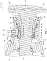
- Fig. 1 shows an embodiment shown in cross-section of a rotary feedthrough according to the invention for a tire inflation system.
- the rotary feedthrough 10 is in the present case part of an attached to a rear axle 12 axle funnel 14 of an agricultural tractor, not shown.
- the rotary feedthrough 10 comprises an axle housing 16 and a wheel axle 18 rotatably mounted in the axle housing 16, for example a rear axle.
- the wheel axle 18 has a Radbefest onlysflansch 20 with a plurality of fastening threads 22, to which by means of associated bolts a wheel rim with a tire thereon can attach (not shown).
- the Radbefest onlysflansch 20 is an integral part of the wheel axle 18, for example, but it can also be provided a two-part design in which the Radbefest onlysflansch 20 along the wheel axle 18 by means of a rack and pinion (so-called rack and pinion axis) is arranged adjustable.
- the axle 18 is at least partially received by a rotatably connected to the wheel axle 18 bushing sleeve 24. Both parts are non-positively and positively, thus airtight connected to each other, which takes place for example by press-fitting or shrink-fitting the bushing 24 to the wheel axle 18.
- the feedthrough sleeve 24 is supported by means of a radial bearing 26 with respect to a arranged in the direction of the Radbefest Trentsflanschs 20 bearing seat 28 within the axle housing 16.
- An elastic sealing ring 30 prevents undesired penetration of moisture and / or dirt into the radial bearing 26 designed as a conical roller bearing.
- first and second compressed air channels 34, 36 extending within a cylindrical wall 32 of the bushing 24 are provided, which communicate on the one hand with a common pressure port 38 attached to the axle housing 16 and on the other hand with first and second tire ports 40, 42 attached to the bushing.
- the two compressed air channels 34, 36 are arranged opposite one another along the circumference of the cylindrical wall 32 of the feedthrough sleeve 24.
- the bushing 24 is rotatably sealed to an adjacent cylindrical inner side 44 of the axle housing 16 such that an airtightly sealed connection chamber 46 is formed between the common pressure port 38 and the two compressed air channels 34, 36.
- the common pressure connection 38 designed as a vent connection 48 is screwed in the form of a corresponding hose connection fitting into a threaded receptacle formed in the axle housing 16, which merges into a through bore 50 opening into the connection chamber 46.
- a vent connection 48 is screwed in the form of a corresponding hose connection fitting into a threaded receptacle formed in the axle housing 16, which merges into a through bore 50 opening into the connection chamber 46.
- the connecting chamber 46 is formed as a cavity 52 within the axle housing 16 manufactured as a steel casting and surrounds an exposed portion 54 of the wheel axle 18 toroidal.
- the cavity 52 adjoins an inner end face 56 of the feedthrough sleeve 24, wherein the two compressed air channels 34, 36 as at the inner end face 56 of the Feedthrough sleeve 24 in the cavity 52 opening longitudinal bores 58, 60 are formed.
- another bearing seat 62 connects to receive a further radial bearing 64, which is also designed as a conical roller bearing and the inner support of the wheel axle 18 relative to the axle housing 16 is used.
- Another elastic sealing ring 66 prevents leakage of compressed air into adjacent areas of the axle housing 16.
- the feedthrough sleeve 24 extends from the cavity 52 in the direction of an outer end face 68 of the axle housing 16 and has an outer collar 70 there.
- the outer collar 70 is an integral part of the feedthrough sleeve 24 produced as a cast steel part.
- first and second elastic sealing ring pairs 72, 74 For rotatably sealing the sealing sleeve 24 relative to the adjacent cylindrical inner side 44 of the axle housing 16 find example according to first and second elastic sealing ring pairs 72, 74 use, these between a cylindrical outer side 76 of the bushing 24 and the cylindrical inner side 44 of the axle housing 16 and separate first and second annular channels 78, 80 which each communicate with one of the two compressed air channels 34, 36 via associated communication bores 82, 84.
- the two pairs of elastic sealing rings 72, 74 are held in their predetermined position by means of associated fastening rings 86, which engage in circumferential grooves along the cylindrical outer side 76 of the bushing sleeve 24.
- First and second further pressure ports 88, 90 are mounted on the axle housing 16, which open into a respective one of the two annular channels 78, 80 and form associated air supply ports 92, 94.
- the air supply ports 92, 94 are in the form of corresponding hose connection fittings in threaded seats, which are formed side by side in the axle housing 16, screwed.
- each of the two tire connections 40, 42 is inclined at an angle of approximately 45 degrees with respect to the course of the associated longitudinal bore 58, 60 of the compressed air duct 34, 36.
- the tire connections 40, 42 are screwed in the form of corresponding hose connection fittings in formed in the outer collar 70 threaded receptacles.
- An oblique bore 96, 98 opening into the respective longitudinal bore 58, 60 within the outer collar 70 establishes a connection with the relevant tire connection 40, 42.
- the rotatable seal produced by means of the two pairs of elastic seal rings 72, 74 allows the bushing sleeve 24 to rotate freely within the axle housing 16 together with the wheel axle 18, at the same time via the respective compressed air passage 34, 36 between the venting and air supply ports 48, 92, 94 on the one hand and the tire inflation ports 40, 42 on the other hand, a continuous air exchange connection is made.
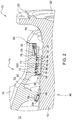
- Fig. 2 Further details of the bushing sleeve 24 are shown. Evident is one of two opposing inside the cylindrical wall 32 extending blind holes 100 which produce a pressure equalization connection between the cavity 52 and the radial bearing 26 surrounding area.
- Fig. 3 shows an exterior view of the rotary feedthrough 10 accommodating axle housing 16.
- the vent or air supply ports 48, 92, 94 of the rotary feedthrough 10 are connected via pressure hoses, not shown, with the tire inflation system. Further pressure hoses make a connection between the Reifenfeldllan Wegn 40, 42 and the vehicle tire or an area bounded by this with the wheel rim inside volume.
- air is vented out of the vehicle tire via the vent port 48.
- the vehicle tire is filled with air from a compressor included in the tire inflation system.
- the corresponding actuation of the tire inflation system or a valve arrangement encompassed by the latter takes place by means of a control device provided in the agricultural tractor.
- a possible constructive implementation of the tire inflation system is for example in the DE 10 2016 203 689 A1 disclosed.
- the rotary feedthrough according to the invention can also be arranged on a front axle of the agricultural tractor. It may also be any other commercial vehicle instead of an agricultural tractor, such as an agricultural vehicle of any type or a construction or forestry machine.
Landscapes
- Engineering & Computer Science (AREA)
- Mechanical Engineering (AREA)
- Tires In General (AREA)
- Joints Allowing Movement (AREA)
Abstract
Description
- Die Erfindung betrifft eine Drehdurchführung für eine Reifenfüllanlage.
- Eine derartige Drehdurchführung ist beispielsweise aus der
US 5 253 688 A bekannt. Die Drehdurchführung umgibt eine Radachse, die innerhalb eines Achskörpers drehbar gelagert ist, und umfasst zwei konzentrisch zueinander angeordnete Ringkörper, zwischen denen ein umlaufender Ringspalt ausgebildet ist. Dieser Ringspalt wird mittels zugehöriger Dichtungen in zwei separate Verbindungskammern unterteilt, die jeweils der Zufuhr von Druckluft über daran angeschlossene Verbindungsleitungen dienen. Hierbei ist der innere Ringkörper drehfest mit der Radachse und der äußere Ringkörper drehfest an einer außenliegenden Stirnseite des Achskörpers befestigt. - Aufgrund der außenliegenden Anordnung der Ringkörper ist die Drehdurchführung von Seiten der Radachse vergleichsweise hohen Biegebeanspruchungen ausgesetzt, was zum frühzeitigen Verschleiß der im Ringspalt angeordneten Dichtungen und damit letztlich zu Betriebsausfällen der Drehdurchführung führen kann.
- Es ist Aufgabe der vorliegenden Erfindung, eine Drehdurchführung der eingangs genannten Art hinsichtlich ihrer Betriebssicherheit zu verbessern.
- Diese Aufgabe wird durch eine Drehdurchführung für eine Reifenfüllanlage mit den Merkmalen des Patentanspruchs 1 gelöst.
- Die Drehdurchführung für eine Reifenfüllanlage umfasst ein Achsgehäuse und eine in dem Achsgehäuse drehbar gelagerte Radachse, die einen Radbefestigungsflansch zur Anbringung einer Radfelge aufweist, wobei die Radachse zumindest abschnittsweise von einer drehfest mit der Radachse verbundenen Durchführungsmuffe aufgenommen ist, die sich mittels eines Radiallagers gegenüber einem Lagersitz innerhalb des Achsgehäuses abstützt, wobei ein innerhalb einer zylindrischen Wandung der Durchführungsmuffe verlaufender Druckluftkanal vorgesehen ist, der einerseits mit einem an dem Achsgehäuse angebrachten Druckanschluss und andererseits mit einem an der Durchführungsmuffe angebrachten Reifenanschluss kommuniziert, wobei die Durchführungsmuffe gegenüber einer angrenzenden Innenseite des Achsgehäuses drehbeweglich derart abgedichtet ist, dass zwischen dem Druckanschluss und dem Druckluftkanal eine luftdicht abgeschlossene Verbindungskammer ausgebildet ist.
- Aufgrund der radialen Abstützung der Durchführungsmuffe innerhalb des Achsgehäuses lassen sich Biegebeanspruchungen, die von Seiten der Radachse auf die Drehdurchführung wirken, effektiv reduzieren. Dies führt zu einem verringerten Verschleiß der zwischen Durchführungsmuffe und Achsgehäuse vorgesehenen drehbeweglichen Abdichtung und damit zu einer entsprechenden Verbesserung der Betriebssicherheit der Drehdurchführung.
- Zur Minimierung der auf die Drehdurchführung wirkenden Biegemomente ist es ferner von Vorteil, wenn der Lagersitz innerhalb des Achsgehäuses bezüglich der Position der drehbeweglichen Abdichtung möglichst weit außenliegend, d.h. in Richtung des Radbefestigungsflanschs angeordnet ist.
- Die drehbewegliche Abdichtung verhindert hierbei einen unkontrollierten Austritt von Druckluft aus dem Achsgehäuse bzw. der Verbindungskammer in die Umgebung. Zur Herstellung der drehbeweglichen Abdichtung findet typischerweise ein elastischer Dichtungsring Verwendung, der in einen zwischen einer zylindrischen Außenseite der Durchführungsmuffe und einer zylindrischen Innenseite des Achsgehäuses gebildeten Ringspalt eingebracht ist.
- Weitere vorteilhafte Ausgestaltungen der erfindungsgemäßen Drehdurchführung gehen aus den Unteransprüchen hervor.
- Vorzugsweise ist die Verbindungskammer als Hohlraum innerhalb des als Stahlgussteil hergestellten Achsgehäuses ausgebildet. Der Hohlraum grenzt insbesondere an eine innenliegende Stirnseite der Durchführungsmuffe an, wobei der Druckluftkanal als an der innenliegenden Stirnseite der Durchführungsmuffe in den Hohlraum mündende Längsbohrung ausgebildet sein kann. An den Hohlraum kann sich ein weiterer Lagersitz zur Aufnahme eines weiteren Radiallagers anschließen, das der innenliegenden Abstützung der Radachse gegenüber dem Achsgehäuse dient.
- Die Durchführungsmuffe kann sich ausgehend von dem Hohlraum in Richtung einer außenliegenden Stirnseite des Achsgehäuses erstrecken und dort einen schützenden Außenkragen aufweisen. Der Außenkragen ist einstückiger Bestandteil der als Stahlgussteil hergestellten Durchführungsmuffe.
- Des Weiteren besteht die Möglichkeit, dass ein weiterer Druckanschluss an dem Achsgehäuse angebracht ist, wobei der weitere Druckanschluss in einen mit dem Druckluftkanal kommunizierenden Ringkanal mündet, der durch ein zwischen einer zylindrischen Außenseite der Durchführungsmuffe und einer zylindrischen Innenseite des Achsgehäuses verlaufendes elastisches Dichtungsringpaar gebildet ist. Das elastische Dichtungsringpaar wird beispielsweise mittels zugehöriger Befestigungsringe, die in umlaufende Nuten entlang der zylindrischen Außenseite der Durchführungsmuffe eingreifen, in seiner vorgegebenen Position gehalten.
- Bei dem Druckanschluss kann es sich um einen Entlüftungsanschluss zum Ablassen von Luft aus einem mit dem Reifenanschluss verbundenen Fahrzeugreifen und bei dem weiteren Druckanschluss um einen Luftzufuhranschluss zur Befüllung des Fahrzeugreifens mit Druckluft aus einem von der Reifenfüllanlage umfassten Kompressor handeln.
- Um das Tempo beim Befüllen des Fahrzeugreifens zu erhöhen, können mehrere bzw. weitere innerhalb der zylindrischen Wandung der Durchführungsmuffe verlaufende Druckluftkanäle vorgesehen sein, wobei jedem der Druckluftkanäle ein separater weiterer Druckanschluss und/oder Reifenanschluss zugeordnet ist. Hierbei mündet jeder der weiteren Druckanschlüsse in einen mit dem betreffenden Druckluftkanal kommunizierenden separaten Ringkanal. Die Ringkanäle sind jeweils durch zugehörige elastische Dichtungsringpaare voneinander getrennt. Die Druckluftkanäle lassen sich beim Befüllen des Fahrzeugreifens parallel schalten, so dass entsprechend hohe Durchflussraten erzielbar sind. Andererseits ist es auch möglich, dass ein erster Reifenanschluss über ein an einer Radfelge montiertes Pneumatikventil mit dem Fahrzeugreifen und ein zweiter Reifenanschluss mit einem Steuereingang des Pneumatikventils verbunden ist. Die Verwendung eines derartigen Pneumatikventils ist bei den meisten gängigen Reifenfüllanlagen üblich. Mögliche Kompatibilitätsprobleme im Falle einer Nachrüstung der Drehdurchführung lassen sich so vermeiden.
- Um eine strukturelle Schwächung der Durchführungsmuffe so gering wie möglich zu halten, kann vorgesehen sein, dass die Druckluftkanäle entlang des Umfangs der zylindrischen Wandung der Durchführungsmuffe gleichmäßig verteilt angeordnet sind.
- Der Reifenanschluss kann von außen leicht zugänglich in einem an der Durchführungsmuffe ausgebildeten Außenkragen angebracht sein. Zu diesem Zweck ist der Reifenanschluss insbesondere in einem Winkel von 30 bis 60 Grad gegenüber dem Verlauf der Längsbohrung des Druckluftkanals geneigt. Eine in die Längsbohrung einmündende Schrägbohrung innerhalb des Außenkragens stellt eine Verbindung mit dem Reifenanschluss her.
- Bei den Anschlüssen handelt es sich üblicherweise um gängige Schlauchanschlussarmaturen, die in am Achsgehäuse sowie der Durchführungsmuffe bzw. deren Außenkragen ausgeformte Gewindeaufnahmen eingeschraubt sind.
- Die erfindungsgemäße Drehdurchführung wird im Folgenden anhand der beigefügten Zeichnungen näher erläutert. Dabei sind hinsichtlich ihrer Funktion übereinstimmende bzw. vergleichbare Bauteile mit denselben Bezugszeichen gekennzeichnet. Es zeigen:
- Fig. 1
- ein im Querschnitt dargestelltes Ausführungsbeispiel einer erfindungsgemäßen Drehdurchführung für eine Reifenfüllanlage,
- Fig. 2
- eine um 90 Grad gedrehte Darstellung der Drehdurchführung gemäß
Fig. 1 , und - Fig. 3
- eine Außenansicht eines die Drehdurchführung gemäß
Fig. 1 beherbergenden Achsgehäuses. -
Fig. 1 zeigt ein im Querschnitt dargestelltes Ausführungsbeispiel einer erfindungsgemäßen Drehdurchführung für eine Reifenfüllanlage. - Die Drehdurchführung 10 ist im vorliegenden Fall Bestandteil eines an einem Hinterachsdifferential 12 angebrachten Achstrichters 14 eines nicht dargestellten landwirtschaftlichen Traktors.
- Die Drehdurchführung 10 umfasst ein Achsgehäuse 16 und eine in dem Achsgehäuse 16 drehbar gelagerte Radachse 18, beispielsgemäß eine Hinterachse. Die Radachse 18 weist einen Radbefestigungsflansch 20 mit einer Vielzahl von Befestigungsgewinden 22 auf, an dem sich mittels zugehöriger Schraubbolzen eine Radfelge mit einem darauf befindlichen Reifen anbringen lässt (nicht dargestellt). Der Radbefestigungsflansch 20 ist beispielsgemäß einstückiger Bestandteil der Radachse 18, es kann jedoch auch eine zweiteilige Ausbildung vorgesehen sein, bei der der Radbefestigungsflansch 20 entlang der Radachse 18 mittels eines Zahnstangengetriebes (sog. Rack and Pinion-Achse) verstellbar angeordnet ist.
- Die Radachse 18 ist zumindest abschnittsweise von einer drehfest mit der Radachse 18 verbundene Durchführungsmuffe 24 aufgenommen. Beide Teile sind kraft- und formschlüssig, mithin luftdicht miteinander verbunden, was beispielsweise durch Pressfügen oder Aufschrumpfen der Durchführungsmuffe 24 auf die Radachse 18 erfolgt.
- Die Durchführungsmuffe 24 stützt sich mittels eines Radiallagers 26 gegenüber einem in Richtung des Radbefestigungsflanschs 20 angeordneten Lagersitz 28 innerhalb des Achsgehäuses 16 ab. Ein elastischer Dichtungsring 30 verhindert dabei ein unerwünschtes Eindringen von Feuchtigkeit und/oder Verschmutzungen in das als konisches Wälzlager ausgebildete Radiallager 26.
- Des Weiteren sind innerhalb einer zylindrischen Wandung 32 der Durchführungsmuffe 24 verlaufende erste und zweite Druckluftkanäle 34, 36 vorgesehen, die einerseits mit einem an dem Achsgehäuse 16 angebrachten gemeinsamen Druckanschluss 38 und andererseits mit an der Durchführungsmuffe 24 angebrachten ersten und zweiten Reifenanschlüssen 40, 42 kommunizieren. Die beiden Druckluftkanäle 34, 36 sind entlang des Umfangs der zylindrischen Wandung 32 der Durchführungsmuffe 24 einander gegenüberliegend angeordnet.
- Genauer gesagt ist die Durchführungsmuffe 24 - wie aus der nachfolgenden Beschreibung im Detail hervorgeht - gegenüber einer angrenzenden zylindrischen Innenseite 44 des Achsgehäuses 16 drehbeweglich derart abgedichtet, dass zwischen dem gemeinsamen Druckanschluss 38 und den beiden Druckluftkanälen 34, 36 eine luftdicht abgeschlossene Verbindungskammer 46 ausgebildet ist.
- Hierbei ist der als Entlüftungsanschluss 48 ausgebildete gemeinsame Druckanschluss 38 in Gestalt einer entsprechenden Schlauchanschlussarmatur in eine in dem Achsgehäuse 16 ausgeformte Gewindeaufnahme eingeschraubt, die in eine in die Verbindungskammer 46 mündende Durchgangsbohrung 50 übergeht. Dies ist am besten aus der in
Fig. 2 um 90 Grad gedrehten Darstellung der Drehdurchführung 10 ersichtlich. - Die Verbindungskammer 46 ist als Hohlraum 52 innerhalb des als Stahlgussteil hergestellten Achsgehäuses 16 ausgebildet und umgibt einen freiliegenden Abschnitt 54 der Radachse 18 torusförmig. Der Hohlraum 52 grenzt an eine innenliegenden Stirnseite 56 der Durchführungsmuffe 24 an, wobei die beiden Druckluftkanäle 34, 36 als an der innenliegenden Stirnseite 56 der Durchführungsmuffe 24 in den Hohlraum 52 mündende Längsbohrungen 58, 60 ausgebildet sind. An den Hohlraum 52 schließt sich ein weiterer Lagersitz 62 zur Aufnahme eines weiteren Radiallagers 64 an, das ebenfalls als konisches Wälzlager ausgebildet ist und der innenliegenden Abstützung der Radachse 18 gegenüber den Achsgehäuse 16 dient. Ein weiterer elastischer Dichtungsring 66 verhindert hierbei einen Austritt von Druckluft in benachbarte Bereiche des Achsgehäuses 16.
- Die Durchführungsmuffe 24 erstreckt sich ausgehend von dem Hohlraum 52 in Richtung einer außenliegenden Stirnseite 68 des Achsgehäuses 16 und weist dort einen Außenkragen 70 auf. Der Außenkragen 70 ist einstückiger Bestandteil der als Stahlgussteil hergestellten Durchführungsmuffe 24.
- Zur drehbeweglichen Abdichtung der Dichtungsmuffe 24 gegenüber der angrenzenden zylindrischen Innenseite 44 des Achsgehäuses 16 finden beispielsgemäß erste und zweite elastische Dichtungsringpaare 72, 74 Verwendung, wobei diese zwischen einer zylindrischen Außenseite 76 der Durchführungsmuffe 24 und der zylindrischen Innenseite 44 des Achsgehäuses 16 verlaufen und voneinander getrennte erste und zweite Ringkanäle 78, 80 ausbilden, die jeweils mit einem der beiden Druckluftkanäle 34, 36 über zugehörige Verbindungsbohrungen 82, 84 kommunizieren. Die beiden elastischen Dichtungsringpaare 72, 74 werden hierbei mittels zugehöriger Befestigungsringe 86, die in umlaufende Nuten entlang der zylindrischen Außenseite 76 der Durchführungsmuffe 24 eingreifen, in ihrer vorgegebenen Position gehalten. Erste und zweite weitere Druckanschlüsse 88, 90 sind an dem Achsgehäuse 16 angebracht, die in einen jeweiligen der beiden Ringkanäle 78, 80 münden und zugehörige Luftzufuhranschlüsse 92, 94 bilden. Die Luftzufuhranschlüsse 92, 94 sind in Gestalt entsprechender Schlauchanschlussarmaturen in Gewindeaufnahmen, die nebeneinander in dem Achsgehäuse 16 ausgeformt sind, eingeschraubt.
- Entsprechendes gilt für die beiden Reifenanschlüsse 40, 42, die von außen leicht zugänglich in dem an der Durchführungsmuffe 24 ausgebildeten Außenkragen 70 angebracht sind. Hierbei ist jeder der beiden Reifenanschlüsse 40, 42 in einem Winkel von etwa 45 Grad gegenüber dem Verlauf der zugehörigen Längsbohrung 58, 60 des Druckluftkanals 34, 36 geneigt. Die Reifenanschlüsse 40, 42 sind in Gestalt entsprechender Schlauchanschlussarmaturen in in dem Außenkragen 70 ausgeformte Gewindeaufnahmen eingeschraubt. Eine in die jeweilige Längsbohrung 58, 60 einmündende Schrägbohrung 96, 98 innerhalb des Außenkragens 70 stellt eine Verbindung mit dem betreffenden Reifenanschluss 40, 42 her.
- Zusammenfassend erlaubt es die mittels der beiden elastischen Dichtungsringpaare 72, 74 hergestellte drehbewegliche Abdichtung, dass sich die Durchführungsmuffe 24 gemeinsam mit der Radachse 18 frei innerhalb des Achsgehäuses 16 drehen kann, wobei zugleich über den jeweiligen Druckluftkanal 34, 36 zwischen den Entlüftungs- bzw. Luftzufuhranschlüssen 48, 92, 94 einerseits und den Reifenfüllanschlüssen 40, 42 andererseits eine kontinuierliche Luftaustauschverbindung hergestellt ist.
- In
Fig. 2 sind weitere Details der Durchführungsmuffe 24 dargestellt. Zu erkennen ist eine von zwei gegenüberliegend innerhalb der zylindrischen Wandung 32 verlaufenden Sackbohrungen 100, die eine Druckausgleichsverbindung zwischen dem Hohlraum 52 und einem das Radiallager 26 umgebenden Bereich herstellen. -
Fig. 3 zeigt eine Außenansicht des die Drehdurchführung 10 beherbergenden Achsgehäuses 16. In am landwirtschaftlichen Traktor eingebautem Zustand sind die Entlüftungs- bzw. Luftzufuhranschlüsse 48, 92, 94 der Drehdurchführung 10 über nicht dargestellte Druckschläuche mit der Reifenfüllanlage verbunden. Weitere Druckschläuche stellen eine Verbindung zwischen den Reifenfüllanschlüssen 40, 42 und dem Fahrzeugreifen bzw. einem von diesem mit der Radfelge umgrenzten Innenvolumen her. Zur Verringerung des Reifenfülldrucks wird Luft über den Entlüftungsanschluss 48 aus dem Fahrzeugreifen abgelassen. Umgekehrt wird der Fahrzeugreifen zur Erhöhung des Reifenfülldrucks über die beiden Luftzufuhranschlüsse 92, 94 mit Luft aus einem von der Reifenfüllanlage umfassten Kompressor befüllt. Die entsprechende Betätigung der Reifenfüllanlage bzw. einer von dieser umfassten Ventilanordnung erfolgt seitens eines in dem landwirtschaftlichen Traktor vorgesehenen Steuergeräts. Eine mögliche konstruktive Umsetzung der Reifenfüllanlage ist beispielsweise in derDE 10 2016 203 689 A1 offenbart. - Der Vollständigkeit halber sei angemerkt, dass die erfindungsgemäße Drehdurchführung auch an einer Vorderachse des landwirtschaftlichen Traktors angeordnet sein kann. Auch kann es sich anstelle eines landwirtschaftlichen Traktors um ein beliebiges anderes Nutzfahrzeug handeln, so zum Beispiel ein landwirtschaftliches Fahrzeug beliebiger Bauart oder eine Bau- bzw. Forstmaschine.
Claims (8)
- Drehdurchführung für eine Reifenfüllanlage, mit einem Achsgehäuse (16) und einer in dem Achsgehäuse (16) drehbar gelagerten Radachse (18), die einen Radbefestigungsflansch (20) zur Anbringung einer Radfelge aufweist, wobei die Radachse (18) zumindest abschnittsweise von einer drehfest mit der Radachse (18) verbundenen Durchführungsmuffe (24) aufgenommen ist, die sich mittels eines Radiallagers (26) gegenüber einem Lagersitz (28) innerhalb des Achsgehäuses (16) abstützt, wobei ein innerhalb einer zylindrischen Wandung (32) der Durchführungsmuffe (24) verlaufender Druckluftkanal (34, 36) vorgesehen ist, der einerseits mit einem an dem Achsgehäuse (16) angebrachten Druckanschluss (38) und andererseits mit einem an der Durchführungsmuffe (24) angebrachten Reifenanschluss (40, 42) kommuniziert, wobei die Durchführungsmuffe (24) gegenüber einer angrenzenden Innenseite (44) des Achsgehäuses (16) drehbeweglich derart abgedichtet ist, dass zwischen dem Druckanschluss (38) und dem Druckluftkanal (34, 36) eine luftdicht abgeschlossene Verbindungskammer (46) ausgebildet ist.
- Drehdurchführung nach Anspruch 1, dadurch gekennzeichnet, dass die Verbindungskammer (46) als Hohlraum (52) innerhalb des Achsgehäuses (16) ausgebildet ist.
- Drehdurchführung nach Anspruch 2, dadurch gekennzeichnet, dass sich die Durchführungsmuffe (24) ausgehend von dem Hohlraum (52) in Richtung einer außenliegenden Stirnseite (68) des Achsgehäuses (16) erstreckt.
- Drehdurchführung nach wenigstens einem der Ansprüche 1 bis 3, dadurch gekennzeichnet, dass ein weiterer Druckanschluss (90, 92) an dem Achsgehäuse (16) angebracht ist, wobei der weitere Druckanschluss (88, 90) in einen mit dem Druckluftkanal (34, 36) kommunizierenden Ringkanal (78, 80) mündet, der durch ein zwischen einer zylindrischen Außenseite (76) der Durchführungsmuffe (24) und einer zylindrischen Innenseite (44) des Achsgehäuses (16) verlaufendes elastisches Dichtungsringpaar (72, 74) gebildet ist.
- Drehdurchführung nach Anspruch 4, dadurch gekennzeichnet, dass weitere innerhalb der zylindrischen Wandung (32) der Durchführungsmuffe (24) verlaufende Druckluftkanäle (34, 36) vorgesehen sind, wobei jedem der Druckluftkanäle (34, 36) ein separater weiterer Druckanschluss (88, 90) und/oder Reifenanschluss (40, 42) zugeordnet ist.
- Drehdurchführung nach Anspruch 5, dadurch gekennzeichnet, dass die Druckluftkanäle (34, 36) entlang des Umfangs der zylindrischen Wandung (32) der Durchführungsmuffe (24) gleichmäßig verteilt angeordnet sind.
- Drehdurchführung nach wenigstens einem der Ansprüche 1 bis 6, dadurch gekennzeichnet, dass der Reifenanschluss (40, 42) in einem an der Durchführungsmuffe (24) ausgebildeten Außenkragen (70) angebracht ist.
- Reifenfüllanlage zur Anpassung eines in einem Fahrzeugreifen herrschenden Reifenfülldrucks, mit einer Drehdurchführung (10) nach wenigstens einem der Ansprüche 1 bis 7.
Applications Claiming Priority (1)
| Application Number | Priority Date | Filing Date | Title |
|---|---|---|---|
| DE102017211574.2A DE102017211574A1 (de) | 2017-07-06 | 2017-07-06 | Drehdurchführung für eine Reifenfüllanlage |
Publications (2)
| Publication Number | Publication Date |
|---|---|
| EP3424755A1 true EP3424755A1 (de) | 2019-01-09 |
| EP3424755B1 EP3424755B1 (de) | 2020-03-25 |
Family
ID=62873238
Family Applications (1)
| Application Number | Title | Priority Date | Filing Date |
|---|---|---|---|
| EP18181687.7A Active EP3424755B1 (de) | 2017-07-06 | 2018-07-04 | Drehdurchführung für eine reifenfüllanlage |
Country Status (4)
| Country | Link |
|---|---|
| US (1) | US11130375B2 (de) |
| EP (1) | EP3424755B1 (de) |
| DE (1) | DE102017211574A1 (de) |
| ES (1) | ES2795199T3 (de) |
Families Citing this family (10)
| Publication number | Priority date | Publication date | Assignee | Title |
|---|---|---|---|---|
| JP6657520B2 (ja) * | 2016-02-03 | 2020-03-04 | 株式会社神戸製鋼所 | タイヤ試験装置のタイヤ空気充填機構及びタイヤ空気充填方法 |
| US11454322B2 (en) | 2019-06-04 | 2022-09-27 | Fairfield Manufacturing Company, Inc. | Rotary pneumatic seal for a central tire inflation system |
| US11602952B2 (en) * | 2020-08-12 | 2023-03-14 | Arvinmeritor Technology, Llc | Wheel end assembly having a vent passage |
| US11117426B1 (en) * | 2021-03-24 | 2021-09-14 | Ptg Reifendruckregelsysteme Gmbh | Rotary transmission leadthrough as part of a tire pressure control system |
| US11845347B2 (en) | 2021-05-12 | 2023-12-19 | David Alan Copeland | Precision charging control of an untethered vehicle with a modular vehicle charging roadway |
| US12583266B2 (en) * | 2022-05-09 | 2026-03-24 | Deere & Company | Tire inflation system |
| US12528318B2 (en) | 2022-05-27 | 2026-01-20 | Deere & Company | Compact rotary union assembly for a wheel hub |
| US20240399800A1 (en) * | 2023-06-05 | 2024-12-05 | Cnh Industrial America Llc | Continuous Tire Inflation System Implementation |
| US12611894B2 (en) * | 2023-06-29 | 2026-04-28 | Rivian Ip Holdings, Llc | Automatic tire inflation system |
| DE102023206643A1 (de) | 2023-07-13 | 2025-01-16 | Zf Friedrichshafen Ag | Reifendruckregelvorrichtung, landwirtschaftliches Nutzfahrzeug und Baumaschine |
Citations (3)
| Publication number | Priority date | Publication date | Assignee | Title |
|---|---|---|---|---|
| GB702621A (en) * | 1950-10-30 | 1954-01-20 | Bendix Westinghouse Automotive | Improvements in or relating to tire inflation control systems |
| DE102013207855A1 (de) * | 2013-04-30 | 2014-10-30 | Schaeffler Technologies Gmbh & Co. Kg | Lager mit Drehdurchführung |
| EP3164273A1 (de) * | 2014-07-02 | 2017-05-10 | DANA ITALIA S.p.A | Drehdichtung für eine zentrale reifenaufpumpanlage |
Family Cites Families (13)
| Publication number | Priority date | Publication date | Assignee | Title |
|---|---|---|---|---|
| US3362452A (en) * | 1966-07-27 | 1968-01-09 | Bendix Corp | Aircraft tire inflation-deflation system |
| US4470506A (en) * | 1981-10-16 | 1984-09-11 | Am General Corporation | Automatic tire inflation system retrofitting kit |
| US4582107A (en) * | 1984-07-26 | 1986-04-15 | The United States Of America As Represented By The Secretary Of The Army | Vehicle tire inflation-deflation mechanism |
| US5236028A (en) * | 1985-07-08 | 1993-08-17 | Am General Corporation | Vehicle wheel end assembly |
| US5174839A (en) * | 1991-07-05 | 1992-12-29 | Eaton Corporation | Drive axle sleeve and seal assembly |
| US5253688A (en) | 1991-09-12 | 1993-10-19 | Tigges & Winckel Bonumwerke | Tire pressure control system |
| AT2364U1 (de) * | 1997-09-09 | 1998-09-25 | Steyr Daimler Puch Ag | Radträger für kraftfahrzeug mit reifenfüllanlage |
| US6145558A (en) * | 1998-12-10 | 2000-11-14 | Case Corporation | Seal arrangement for a central tire inflation system |
| DE19950191C1 (de) | 1999-10-19 | 2001-05-10 | Tigges & Winckel Bonumwerke | Reifendruckregelanlage |
| ES2251564T3 (es) * | 2001-02-22 | 2006-05-01 | Arvinmeritor Technology, Llc | Montaje de extremo de rueda de vehiculo. |
| JP2005195168A (ja) * | 2003-12-10 | 2005-07-21 | Ntn Corp | 車輪用軸受およびそれを備えたセミフローティングタイプの車輪用軸受装置 |
| US9452644B2 (en) * | 2013-09-18 | 2016-09-27 | Arvinmeritor Technology, Llc | Tire inflation system with a passage for routing pressurized gas |
| DE102016203689A1 (de) | 2016-03-07 | 2017-09-07 | Deere & Company | Einrichtung zur Reifenfülldrucküberwachung eines Fahrzeugsystems |
-
2017
- 2017-07-06 DE DE102017211574.2A patent/DE102017211574A1/de not_active Withdrawn
-
2018
- 2018-06-13 US US16/007,469 patent/US11130375B2/en active Active
- 2018-07-04 ES ES18181687T patent/ES2795199T3/es active Active
- 2018-07-04 EP EP18181687.7A patent/EP3424755B1/de active Active
Patent Citations (3)
| Publication number | Priority date | Publication date | Assignee | Title |
|---|---|---|---|---|
| GB702621A (en) * | 1950-10-30 | 1954-01-20 | Bendix Westinghouse Automotive | Improvements in or relating to tire inflation control systems |
| DE102013207855A1 (de) * | 2013-04-30 | 2014-10-30 | Schaeffler Technologies Gmbh & Co. Kg | Lager mit Drehdurchführung |
| EP3164273A1 (de) * | 2014-07-02 | 2017-05-10 | DANA ITALIA S.p.A | Drehdichtung für eine zentrale reifenaufpumpanlage |
Also Published As
| Publication number | Publication date |
|---|---|
| US11130375B2 (en) | 2021-09-28 |
| EP3424755B1 (de) | 2020-03-25 |
| DE102017211574A1 (de) | 2019-01-10 |
| US20190009622A1 (en) | 2019-01-10 |
| ES2795199T3 (es) | 2020-11-23 |
Similar Documents
| Publication | Publication Date | Title |
|---|---|---|
| EP3424755B1 (de) | Drehdurchführung für eine reifenfüllanlage | |
| EP2586630B1 (de) | Drehdurchführung | |
| EP3341225B1 (de) | Drehdurchführung einer reifendruckregelanlage sowie anordnung umfassend eine solche drehdurchführung sowie eine auf einem achsstummel gelagerte nabe | |
| EP3962758B1 (de) | Nabenabdeckung für eine reifenbefüllvorrichtung eines fahrzeugs | |
| EP2810795B1 (de) | Drehdurchführung | |
| DE102004021161B4 (de) | Drehdurchführung einer Reifendruckregelung | |
| EP1874563B1 (de) | Vorrichtung, insbesondere drehdurchführung | |
| EP2170630B1 (de) | Druckluftreifen-ventilvorrichtung und system und verfahren zur einstellung des reifendrucks | |
| DE10208024A1 (de) | Drehdurchführung für eine Vorrichtung zum Füllen oder Entlüften eines Reifens eines Traktorrades | |
| DE102013223512A1 (de) | Radantrieb mit Drehdurchführung | |
| EP1920888B1 (de) | Impulswerkzeug und zugehörige Vorderplatte | |
| EP1628019B1 (de) | Schwenkmotor mit einem Druckbegrenzungsventil | |
| DE102005006073A1 (de) | Vorrichtung, insbesondere Drehdurchführung | |
| DE102011007231B4 (de) | Radlageranordnung, insbesondere Radlageranordnung für Nutzfahrzeuge | |
| WO2014154422A1 (de) | Radnabenantrieb mit einem planetengetriebe | |
| DE10302444B4 (de) | Radlagerung für ein Fahrzeugrad | |
| DE102014221813B3 (de) | Einrichtung zur Einstellung des Luftdrucks eines an einer Fahrzeugachse über eine Felge angeordneten Luftreifens | |
| WO2025012252A1 (de) | Reifendruckregelvorrichtung, landwirtschaftliches nutzfahrzeug und baumaschine | |
| EP3165382B1 (de) | Befülleinrichtung | |
| DE102014210598A1 (de) | Antreibbarer lenkbarer Radkopf | |
| WO2014135164A1 (de) | Drehdurchführung und reifendruckregulierungsanlage mit drehdurchführung | |
| DE102011100660A1 (de) | Achsschenkelelement für einen Kraftwagen, insbesondere Nutzkraftwagen, sowie Antriebseinrichtung für einen Kraftwagen mit einem solchen Achsschenkelelement | |
| DE102014219982A1 (de) | Ventilanordnung für eine Druckluftversorgung eines Rades eines Fahrzeuges | |
| EP3882048B1 (de) | Fahrzeugrad-drehdurchführung, fahrzeugrad-baugruppe, selbstfahrende arbeitsmaschine und verfahren zum betrieb einer fahrzeugrad-drehdurchführung | |
| DE10136250C2 (de) | Ventilkupplung für fluidische Systeme |
Legal Events
| Date | Code | Title | Description |
|---|---|---|---|
| PUAI | Public reference made under article 153(3) epc to a published international application that has entered the european phase |
Free format text: ORIGINAL CODE: 0009012 |
|
| STAA | Information on the status of an ep patent application or granted ep patent |
Free format text: STATUS: THE APPLICATION HAS BEEN PUBLISHED |
|
| AK | Designated contracting states |
Kind code of ref document: A1 Designated state(s): AL AT BE BG CH CY CZ DE DK EE ES FI FR GB GR HR HU IE IS IT LI LT LU LV MC MK MT NL NO PL PT RO RS SE SI SK SM TR |
|
| AX | Request for extension of the european patent |
Extension state: BA ME |
|
| STAA | Information on the status of an ep patent application or granted ep patent |
Free format text: STATUS: REQUEST FOR EXAMINATION WAS MADE |
|
| 17P | Request for examination filed |
Effective date: 20190709 |
|
| RBV | Designated contracting states (corrected) |
Designated state(s): AL AT BE BG CH CY CZ DE DK EE ES FI FR GB GR HR HU IE IS IT LI LT LU LV MC MK MT NL NO PL PT RO RS SE SI SK SM TR |
|
| GRAP | Despatch of communication of intention to grant a patent |
Free format text: ORIGINAL CODE: EPIDOSNIGR1 |
|
| STAA | Information on the status of an ep patent application or granted ep patent |
Free format text: STATUS: GRANT OF PATENT IS INTENDED |
|
| INTG | Intention to grant announced |
Effective date: 20191017 |
|
| GRAS | Grant fee paid |
Free format text: ORIGINAL CODE: EPIDOSNIGR3 |
|
| GRAA | (expected) grant |
Free format text: ORIGINAL CODE: 0009210 |
|
| STAA | Information on the status of an ep patent application or granted ep patent |
Free format text: STATUS: THE PATENT HAS BEEN GRANTED |
|
| AK | Designated contracting states |
Kind code of ref document: B1 Designated state(s): AL AT BE BG CH CY CZ DE DK EE ES FI FR GB GR HR HU IE IS IT LI LT LU LV MC MK MT NL NO PL PT RO RS SE SI SK SM TR |
|
| REG | Reference to a national code |
Ref country code: GB Ref legal event code: FG4D Free format text: NOT ENGLISH |
|
| REG | Reference to a national code |
Ref country code: AT Ref legal event code: REF Ref document number: 1248168 Country of ref document: AT Kind code of ref document: T Effective date: 20200415 Ref country code: IE Ref legal event code: FG4D Free format text: LANGUAGE OF EP DOCUMENT: GERMAN |
|
| REG | Reference to a national code |
Ref country code: DE Ref legal event code: R096 Ref document number: 502018001020 Country of ref document: DE |
|
| REG | Reference to a national code |
Ref country code: FI Ref legal event code: FGE |
|
| REG | Reference to a national code |
Ref country code: SE Ref legal event code: TRGR |
|
| PG25 | Lapsed in a contracting state [announced via postgrant information from national office to epo] |
Ref country code: NO Free format text: LAPSE BECAUSE OF FAILURE TO SUBMIT A TRANSLATION OF THE DESCRIPTION OR TO PAY THE FEE WITHIN THE PRESCRIBED TIME-LIMIT Effective date: 20200625 Ref country code: RS Free format text: LAPSE BECAUSE OF FAILURE TO SUBMIT A TRANSLATION OF THE DESCRIPTION OR TO PAY THE FEE WITHIN THE PRESCRIBED TIME-LIMIT Effective date: 20200325 |
|
| PG25 | Lapsed in a contracting state [announced via postgrant information from national office to epo] |
Ref country code: GR Free format text: LAPSE BECAUSE OF FAILURE TO SUBMIT A TRANSLATION OF THE DESCRIPTION OR TO PAY THE FEE WITHIN THE PRESCRIBED TIME-LIMIT Effective date: 20200626 Ref country code: HR Free format text: LAPSE BECAUSE OF FAILURE TO SUBMIT A TRANSLATION OF THE DESCRIPTION OR TO PAY THE FEE WITHIN THE PRESCRIBED TIME-LIMIT Effective date: 20200325 Ref country code: BG Free format text: LAPSE BECAUSE OF FAILURE TO SUBMIT A TRANSLATION OF THE DESCRIPTION OR TO PAY THE FEE WITHIN THE PRESCRIBED TIME-LIMIT Effective date: 20200625 Ref country code: LV Free format text: LAPSE BECAUSE OF FAILURE TO SUBMIT A TRANSLATION OF THE DESCRIPTION OR TO PAY THE FEE WITHIN THE PRESCRIBED TIME-LIMIT Effective date: 20200325 |
|
| REG | Reference to a national code |
Ref country code: NL Ref legal event code: MP Effective date: 20200325 |
|
| REG | Reference to a national code |
Ref country code: LT Ref legal event code: MG4D |
|
| PG25 | Lapsed in a contracting state [announced via postgrant information from national office to epo] |
Ref country code: NL Free format text: LAPSE BECAUSE OF FAILURE TO SUBMIT A TRANSLATION OF THE DESCRIPTION OR TO PAY THE FEE WITHIN THE PRESCRIBED TIME-LIMIT Effective date: 20200325 |
|
| PG25 | Lapsed in a contracting state [announced via postgrant information from national office to epo] |
Ref country code: EE Free format text: LAPSE BECAUSE OF FAILURE TO SUBMIT A TRANSLATION OF THE DESCRIPTION OR TO PAY THE FEE WITHIN THE PRESCRIBED TIME-LIMIT Effective date: 20200325 Ref country code: LT Free format text: LAPSE BECAUSE OF FAILURE TO SUBMIT A TRANSLATION OF THE DESCRIPTION OR TO PAY THE FEE WITHIN THE PRESCRIBED TIME-LIMIT Effective date: 20200325 Ref country code: SM Free format text: LAPSE BECAUSE OF FAILURE TO SUBMIT A TRANSLATION OF THE DESCRIPTION OR TO PAY THE FEE WITHIN THE PRESCRIBED TIME-LIMIT Effective date: 20200325 Ref country code: IS Free format text: LAPSE BECAUSE OF FAILURE TO SUBMIT A TRANSLATION OF THE DESCRIPTION OR TO PAY THE FEE WITHIN THE PRESCRIBED TIME-LIMIT Effective date: 20200725 Ref country code: RO Free format text: LAPSE BECAUSE OF FAILURE TO SUBMIT A TRANSLATION OF THE DESCRIPTION OR TO PAY THE FEE WITHIN THE PRESCRIBED TIME-LIMIT Effective date: 20200325 Ref country code: SK Free format text: LAPSE BECAUSE OF FAILURE TO SUBMIT A TRANSLATION OF THE DESCRIPTION OR TO PAY THE FEE WITHIN THE PRESCRIBED TIME-LIMIT Effective date: 20200325 Ref country code: PT Free format text: LAPSE BECAUSE OF FAILURE TO SUBMIT A TRANSLATION OF THE DESCRIPTION OR TO PAY THE FEE WITHIN THE PRESCRIBED TIME-LIMIT Effective date: 20200818 |
|
| REG | Reference to a national code |
Ref country code: ES Ref legal event code: FG2A Ref document number: 2795199 Country of ref document: ES Kind code of ref document: T3 Effective date: 20201123 |
|
| REG | Reference to a national code |
Ref country code: DE Ref legal event code: R097 Ref document number: 502018001020 Country of ref document: DE |
|
| PG25 | Lapsed in a contracting state [announced via postgrant information from national office to epo] |
Ref country code: DK Free format text: LAPSE BECAUSE OF FAILURE TO SUBMIT A TRANSLATION OF THE DESCRIPTION OR TO PAY THE FEE WITHIN THE PRESCRIBED TIME-LIMIT Effective date: 20200325 |
|
| PLBE | No opposition filed within time limit |
Free format text: ORIGINAL CODE: 0009261 |
|
| STAA | Information on the status of an ep patent application or granted ep patent |
Free format text: STATUS: NO OPPOSITION FILED WITHIN TIME LIMIT |
|
| PG25 | Lapsed in a contracting state [announced via postgrant information from national office to epo] |
Ref country code: MC Free format text: LAPSE BECAUSE OF FAILURE TO SUBMIT A TRANSLATION OF THE DESCRIPTION OR TO PAY THE FEE WITHIN THE PRESCRIBED TIME-LIMIT Effective date: 20200325 Ref country code: PL Free format text: LAPSE BECAUSE OF FAILURE TO SUBMIT A TRANSLATION OF THE DESCRIPTION OR TO PAY THE FEE WITHIN THE PRESCRIBED TIME-LIMIT Effective date: 20200325 |
|
| 26N | No opposition filed |
Effective date: 20210112 |
|
| REG | Reference to a national code |
Ref country code: BE Ref legal event code: MM Effective date: 20200731 |
|
| PG25 | Lapsed in a contracting state [announced via postgrant information from national office to epo] |
Ref country code: LU Free format text: LAPSE BECAUSE OF NON-PAYMENT OF DUE FEES Effective date: 20200704 Ref country code: IE Free format text: LAPSE BECAUSE OF NON-PAYMENT OF DUE FEES Effective date: 20200704 |
|
| PG25 | Lapsed in a contracting state [announced via postgrant information from national office to epo] |
Ref country code: BE Free format text: LAPSE BECAUSE OF NON-PAYMENT OF DUE FEES Effective date: 20200731 Ref country code: SI Free format text: LAPSE BECAUSE OF FAILURE TO SUBMIT A TRANSLATION OF THE DESCRIPTION OR TO PAY THE FEE WITHIN THE PRESCRIBED TIME-LIMIT Effective date: 20200325 |
|
| REG | Reference to a national code |
Ref country code: CH Ref legal event code: PL |
|
| PG25 | Lapsed in a contracting state [announced via postgrant information from national office to epo] |
Ref country code: LI Free format text: LAPSE BECAUSE OF NON-PAYMENT OF DUE FEES Effective date: 20210731 Ref country code: CH Free format text: LAPSE BECAUSE OF NON-PAYMENT OF DUE FEES Effective date: 20210731 |
|
| PG25 | Lapsed in a contracting state [announced via postgrant information from national office to epo] |
Ref country code: TR Free format text: LAPSE BECAUSE OF FAILURE TO SUBMIT A TRANSLATION OF THE DESCRIPTION OR TO PAY THE FEE WITHIN THE PRESCRIBED TIME-LIMIT Effective date: 20200325 Ref country code: MT Free format text: LAPSE BECAUSE OF FAILURE TO SUBMIT A TRANSLATION OF THE DESCRIPTION OR TO PAY THE FEE WITHIN THE PRESCRIBED TIME-LIMIT Effective date: 20200325 Ref country code: CY Free format text: LAPSE BECAUSE OF FAILURE TO SUBMIT A TRANSLATION OF THE DESCRIPTION OR TO PAY THE FEE WITHIN THE PRESCRIBED TIME-LIMIT Effective date: 20200325 |
|
| PG25 | Lapsed in a contracting state [announced via postgrant information from national office to epo] |
Ref country code: MK Free format text: LAPSE BECAUSE OF FAILURE TO SUBMIT A TRANSLATION OF THE DESCRIPTION OR TO PAY THE FEE WITHIN THE PRESCRIBED TIME-LIMIT Effective date: 20200325 Ref country code: AL Free format text: LAPSE BECAUSE OF FAILURE TO SUBMIT A TRANSLATION OF THE DESCRIPTION OR TO PAY THE FEE WITHIN THE PRESCRIBED TIME-LIMIT Effective date: 20200325 |
|
| PGFP | Annual fee paid to national office [announced via postgrant information from national office to epo] |
Ref country code: CZ Payment date: 20250620 Year of fee payment: 8 |
|
| PGFP | Annual fee paid to national office [announced via postgrant information from national office to epo] |
Ref country code: FI Payment date: 20250725 Year of fee payment: 8 Ref country code: ES Payment date: 20250801 Year of fee payment: 8 |
|
| PGFP | Annual fee paid to national office [announced via postgrant information from national office to epo] |
Ref country code: DE Payment date: 20250620 Year of fee payment: 8 |
|
| PGFP | Annual fee paid to national office [announced via postgrant information from national office to epo] |
Ref country code: IT Payment date: 20250721 Year of fee payment: 8 |
|
| PGFP | Annual fee paid to national office [announced via postgrant information from national office to epo] |
Ref country code: GB Payment date: 20250728 Year of fee payment: 8 |
|
| PGFP | Annual fee paid to national office [announced via postgrant information from national office to epo] |
Ref country code: AT Payment date: 20250620 Year of fee payment: 8 Ref country code: FR Payment date: 20250725 Year of fee payment: 8 |
|
| PGFP | Annual fee paid to national office [announced via postgrant information from national office to epo] |
Ref country code: SE Payment date: 20250727 Year of fee payment: 8 |