EP3424617A1 - Device for injecting molten material, casting equipment using same, and casting method - Google Patents
Device for injecting molten material, casting equipment using same, and casting method Download PDFInfo
- Publication number
- EP3424617A1 EP3424617A1 EP16892800.0A EP16892800A EP3424617A1 EP 3424617 A1 EP3424617 A1 EP 3424617A1 EP 16892800 A EP16892800 A EP 16892800A EP 3424617 A1 EP3424617 A1 EP 3424617A1
- Authority
- EP
- European Patent Office
- Prior art keywords
- mold
- molten
- raw material
- mold flux
- casting
- Prior art date
- Legal status (The legal status is an assumption and is not a legal conclusion. Google has not performed a legal analysis and makes no representation as to the accuracy of the status listed.)
- Withdrawn
Links
- 238000005266 casting Methods 0.000 title claims abstract description 143
- 238000000034 method Methods 0.000 title claims abstract description 43
- 239000012768 molten material Substances 0.000 title claims abstract description 31
- 230000004907 flux Effects 0.000 claims abstract description 226
- 239000000654 additive Substances 0.000 claims abstract description 137
- 230000000996 additive effect Effects 0.000 claims abstract description 119
- 229910000831 Steel Inorganic materials 0.000 claims abstract description 102
- 239000010959 steel Substances 0.000 claims abstract description 102
- 238000002844 melting Methods 0.000 claims abstract description 57
- 230000008018 melting Effects 0.000 claims abstract description 57
- 239000002994 raw material Substances 0.000 claims description 105
- 239000000203 mixture Substances 0.000 claims description 42
- 238000003723 Smelting Methods 0.000 claims description 40
- 238000003860 storage Methods 0.000 claims description 39
- 230000008859 change Effects 0.000 claims description 35
- 238000012546 transfer Methods 0.000 claims description 35
- 238000005259 measurement Methods 0.000 claims description 14
- 239000000523 sample Substances 0.000 claims description 7
- 238000004891 communication Methods 0.000 claims description 4
- 238000002347 injection Methods 0.000 claims description 4
- 239000007924 injection Substances 0.000 claims description 4
- 239000000463 material Substances 0.000 claims description 3
- 239000002893 slag Substances 0.000 description 61
- PNEYBMLMFCGWSK-UHFFFAOYSA-N aluminium oxide Inorganic materials [O-2].[O-2].[O-2].[Al+3].[Al+3] PNEYBMLMFCGWSK-UHFFFAOYSA-N 0.000 description 19
- 229910052593 corundum Inorganic materials 0.000 description 19
- 229910001845 yogo sapphire Inorganic materials 0.000 description 19
- VYPSYNLAJGMNEJ-UHFFFAOYSA-N Silicium dioxide Chemical compound O=[Si]=O VYPSYNLAJGMNEJ-UHFFFAOYSA-N 0.000 description 14
- GWEVSGVZZGPLCZ-UHFFFAOYSA-N Titan oxide Chemical compound O=[Ti]=O GWEVSGVZZGPLCZ-UHFFFAOYSA-N 0.000 description 14
- DLYUQMMRRRQYAE-UHFFFAOYSA-N tetraphosphorus decaoxide Chemical compound O1P(O2)(=O)OP3(=O)OP1(=O)OP2(=O)O3 DLYUQMMRRRQYAE-UHFFFAOYSA-N 0.000 description 14
- 230000001276 controlling effect Effects 0.000 description 11
- KKCBUQHMOMHUOY-UHFFFAOYSA-N Na2O Inorganic materials [O-2].[Na+].[Na+] KKCBUQHMOMHUOY-UHFFFAOYSA-N 0.000 description 9
- 239000007787 solid Substances 0.000 description 9
- 229910052681 coesite Inorganic materials 0.000 description 7
- 238000009749 continuous casting Methods 0.000 description 7
- 229910052906 cristobalite Inorganic materials 0.000 description 7
- JEIPFZHSYJVQDO-UHFFFAOYSA-N iron(III) oxide Inorganic materials O=[Fe]O[Fe]=O JEIPFZHSYJVQDO-UHFFFAOYSA-N 0.000 description 7
- NOTVAPJNGZMVSD-UHFFFAOYSA-N potassium monoxide Inorganic materials [K]O[K] NOTVAPJNGZMVSD-UHFFFAOYSA-N 0.000 description 7
- 239000000377 silicon dioxide Substances 0.000 description 7
- 229910052682 stishovite Inorganic materials 0.000 description 7
- 229910052905 tridymite Inorganic materials 0.000 description 7
- KLZUFWVZNOTSEM-UHFFFAOYSA-K Aluminium flouride Chemical compound F[Al](F)F KLZUFWVZNOTSEM-UHFFFAOYSA-K 0.000 description 6
- 238000010586 diagram Methods 0.000 description 6
- YCKRFDGAMUMZLT-UHFFFAOYSA-N Fluorine atom Chemical compound [F] YCKRFDGAMUMZLT-UHFFFAOYSA-N 0.000 description 5
- 229910001610 cryolite Inorganic materials 0.000 description 5
- 229910052731 fluorine Inorganic materials 0.000 description 5
- 239000011737 fluorine Substances 0.000 description 5
- 239000012535 impurity Substances 0.000 description 5
- WUKWITHWXAAZEY-UHFFFAOYSA-L calcium difluoride Chemical compound [F-].[F-].[Ca+2] WUKWITHWXAAZEY-UHFFFAOYSA-L 0.000 description 4
- 229910001634 calcium fluoride Inorganic materials 0.000 description 4
- ODINCKMPIJJUCX-UHFFFAOYSA-N calcium oxide Inorganic materials [Ca]=O ODINCKMPIJJUCX-UHFFFAOYSA-N 0.000 description 4
- 239000007789 gas Substances 0.000 description 4
- 230000001050 lubricating effect Effects 0.000 description 4
- CPLXHLVBOLITMK-UHFFFAOYSA-N magnesium oxide Inorganic materials [Mg]=O CPLXHLVBOLITMK-UHFFFAOYSA-N 0.000 description 4
- VASIZKWUTCETSD-UHFFFAOYSA-N manganese(II) oxide Inorganic materials [Mn]=O VASIZKWUTCETSD-UHFFFAOYSA-N 0.000 description 4
- FUJCRWPEOMXPAD-UHFFFAOYSA-N Li2O Inorganic materials [Li+].[Li+].[O-2] FUJCRWPEOMXPAD-UHFFFAOYSA-N 0.000 description 3
- 230000006866 deterioration Effects 0.000 description 3
- XUCJHNOBJLKZNU-UHFFFAOYSA-M dilithium;hydroxide Chemical compound [Li+].[Li+].[OH-] XUCJHNOBJLKZNU-UHFFFAOYSA-M 0.000 description 3
- 230000006698 induction Effects 0.000 description 3
- 230000000704 physical effect Effects 0.000 description 3
- 230000004044 response Effects 0.000 description 3
- 230000001052 transient effect Effects 0.000 description 3
- XKRFYHLGVUSROY-UHFFFAOYSA-N Argon Chemical compound [Ar] XKRFYHLGVUSROY-UHFFFAOYSA-N 0.000 description 2
- 229910052782 aluminium Inorganic materials 0.000 description 2
- 238000001816 cooling Methods 0.000 description 2
- 238000007599 discharging Methods 0.000 description 2
- 238000010438 heat treatment Methods 0.000 description 2
- 238000004519 manufacturing process Methods 0.000 description 2
- 230000008569 process Effects 0.000 description 2
- 238000007670 refining Methods 0.000 description 2
- PUZPDOWCWNUUKD-UHFFFAOYSA-M sodium fluoride Chemical compound [F-].[Na+] PUZPDOWCWNUUKD-UHFFFAOYSA-M 0.000 description 2
- IJGRMHOSHXDMSA-UHFFFAOYSA-N Atomic nitrogen Chemical compound N#N IJGRMHOSHXDMSA-UHFFFAOYSA-N 0.000 description 1
- 229910000617 Mangalloy Inorganic materials 0.000 description 1
- XAGFODPZIPBFFR-UHFFFAOYSA-N aluminium Chemical compound [Al] XAGFODPZIPBFFR-UHFFFAOYSA-N 0.000 description 1
- 229910052786 argon Inorganic materials 0.000 description 1
- 238000007664 blowing Methods 0.000 description 1
- 239000003795 chemical substances by application Substances 0.000 description 1
- 238000005336 cracking Methods 0.000 description 1
- 230000007423 decrease Effects 0.000 description 1
- 230000007547 defect Effects 0.000 description 1
- 230000005611 electricity Effects 0.000 description 1
- 238000005516 engineering process Methods 0.000 description 1
- 239000001307 helium Substances 0.000 description 1
- 229910052734 helium Inorganic materials 0.000 description 1
- SWQJXJOGLNCZEY-UHFFFAOYSA-N helium atom Chemical compound [He] SWQJXJOGLNCZEY-UHFFFAOYSA-N 0.000 description 1
- 239000011261 inert gas Substances 0.000 description 1
- 239000007788 liquid Substances 0.000 description 1
- XGZVUEUWXADBQD-UHFFFAOYSA-L lithium carbonate Chemical compound [Li+].[Li+].[O-]C([O-])=O XGZVUEUWXADBQD-UHFFFAOYSA-L 0.000 description 1
- 229910052808 lithium carbonate Inorganic materials 0.000 description 1
- 238000005461 lubrication Methods 0.000 description 1
- 239000011572 manganese Substances 0.000 description 1
- 239000000155 melt Substances 0.000 description 1
- 238000012986 modification Methods 0.000 description 1
- 230000004048 modification Effects 0.000 description 1
- 238000012544 monitoring process Methods 0.000 description 1
- 238000000465 moulding Methods 0.000 description 1
- 239000000843 powder Substances 0.000 description 1
- 230000001105 regulatory effect Effects 0.000 description 1
- 238000005507 spraying Methods 0.000 description 1
- 238000009628 steelmaking Methods 0.000 description 1
Images


Classifications
-
- B—PERFORMING OPERATIONS; TRANSPORTING
- B22—CASTING; POWDER METALLURGY
- B22D—CASTING OF METALS; CASTING OF OTHER SUBSTANCES BY THE SAME PROCESSES OR DEVICES
- B22D11/00—Continuous casting of metals, i.e. casting in indefinite lengths
- B22D11/16—Controlling or regulating processes or operations
- B22D11/165—Controlling or regulating processes or operations for the supply of casting powder
-
- B—PERFORMING OPERATIONS; TRANSPORTING
- B22—CASTING; POWDER METALLURGY
- B22D—CASTING OF METALS; CASTING OF OTHER SUBSTANCES BY THE SAME PROCESSES OR DEVICES
- B22D11/00—Continuous casting of metals, i.e. casting in indefinite lengths
- B22D11/10—Supplying or treating molten metal
- B22D11/108—Feeding additives, powders, or the like
Definitions
- the present disclosure relates to a device for injecting molten material, a casting equipment using the same, and a casting method. More specifically, the present disclosure relates to a device for injecting molten material able to improve a quality and productivity of a slab, a casting equipment using the same, and a casting method.
- a device for injecting molten material for example a device for injecting molten mold flux used in a slab casting process, is an equipment that melts the mold flux in powder and supplies it to a mold.
- Typical molten mold flux injecting equipment includes a hopper configured for storing the mold flux therein, a smelting furnace configured for receiving the mold flux from the hopper and melting it, and a torch disposed at one side of the smelting furnace and configured for melting the mold flux by spraying a flame into the smelting furnace.
- a discharge port configured for discharging the molten mold flux may be defined.
- a temperature drop of molten steel in the mold may be suppressed, and at the same time a lubricating ability may be improved to reduce a defect of the slab.
- the component of the mold flux changes due to a reaction between impurities contained in the steel and the mold flux.
- a viscosity of the mold flux is increased.
- the mold flux does not inflow smoothly between the mold and the slab (solidified shell), therefore a heat transfer between the molten steel and the mold becomes uneven and the lubricating ability decreases.
- an operation accident such as a solidified shell break-out or a crack on a surface of the slab occurs.
- Such change in the components of the mold flux may lead to difficulty in carrying out multiple continuous-castings of a single steel grade at least one charge.
- the present disclosure provides a device for injecting molten material which is able to improve a casting efficiency, a casting equipment using the same, and a casting method.
- the present disclosure provides a device for injecting molten material which is able to improve a quality of a slab, a casting equipment using the same, and a casting method.
- the device may comprise: raw material supply units configured for supplying different first and second raw materials respectively; a mixing unit configured for mixing the different first and second raw materials supplied from the raw material supply units to produce a mixture; a melting unit connected to the mixing unit to melt the mixture supplied from the mixing unit to produce molten material, and the melting unit has a discharge port through which the molten material is discharged; and a control unit configured for controlling a component of the mixture by controlling operations of the raw material supply units, mixing unit and melting unit.
- the raw material supply unit may include: a first raw material supply unit configured for supplying a first raw material; and second raw material supply units configured for respectively supplying a plurality of second raw materials containing different components.
- the first raw material supply unit may include: a first storage unit configured for storing the first raw material therein; a first transfer pipe for communicating the first storage unit and the mixing unit; and a first feeder coupled to at least one of the first storage unit and the first transfer pipe to regulate a discharge amount of the first raw material.
- Each of the second raw material supply unit may include: a second storage unit configured for storing each of the plurality of second raw materials therein; a second transfer pipe configured for communicating each of the plurality of second storage units and the mixing unit; and a second feeder coupled to at least one of the second storage unit and the second transfer pipe to regulate a discharge amount of each of the second raw material.
- the mixing unit may include: a mixing vessel in communication with the first supply pipe and the second supply pipe; an agitator disposed in the mixing vessel for mixing the first raw material and the second raw material; and a third transfer pipe for transferring the mixture of the first raw material and the second material to the melting unit.
- the mixing unit may include a mixing vessel in communication with the first supply pipe and the second supply pipe, and the mixing vessel is rotatable.
- the melting unit may include: a smelting furnace having a smelting space defined therein for receiving the first raw material and the second raw material therein; a heat source supply unit disposed at one side of the smelting furnace to supply a heat source to the smelting space.
- the heat source supply unit uses plasma as the heat source.
- the control unit may be configured to determine whether or not to inject the second raw material based on an input signal.
- a casting equipment may comprise: a mold for receiving and initially solidifying molten steel; a device for injecting molten mold flux into the mold; a measuring unit configured for measuring temperatures of at least one of a temperature of the mold and a component of the molten mold flux injected into the mold; and a control unit configured for controlling an operation of the device based on a measurement from the measuring unit to change the component of the molten mold flux to be injected into the mold.
- the device may include: a first raw material supply unit configured for supplying main mold flux; second raw material supply units configured for supplying additives; a mixing unit configured for mixing the main mold flux and the additives respectively supplied from the first raw material supply unit and the second raw material supply units, thereby to produce a mixture; and a melting unit configured for melting the mixture supplied from the mixing unit to produce molten mold flux, and for injecting the molten mold flux into the mold.
- the second raw material supply units may store therein the plurality of additives individually, and the second supply units feed selectively the plurality of additives to the mixing unit.
- the measuring unit may include a thermometer configured for measuring a temperature of the mold.
- the measuring unit may include: a probe configured for collecting molten mold flux injected into the mold; an analyzing unit configured for analyzing a component of the molten mold flux collected by the probe.
- the control unit may be configured to determine whether to input the additives using a measurement from the measuring unit, and to control types and input amounts of the additives by controlling the second raw material supply units based on the measurement.
- a casting method may comprise: preparing main mod flux; injecting molten steel into a mold; melting the main mold flux to produce molten mold flux and injecting the molten mold flux onto a top face of the molten steel; casting a slab; and determining whether to input an additive based on a casted state of the slab during casting thereof.
- the additive may be prepared.
- the main mold flux and the additive may be melted together.
- a temperature of the mold may be measured to indicate the casted state of the slab, and the method may include determining whether to input the additive based on the measured temperature of the mold.
- a component of the molten mold flux injected into the mold may be analyzed to indicate the casted state of the slab, the method may include determining whether to input the additive based on the analyzed component of the molten mold flux.
- the method may include, upon determination that the additive is added, mixing the main mold flux and the additive to form a mixture, and melting the mixture, and injecting molten mold flux containing a changed component into the mold.
- the method may include, when, in casting the slab, a grade of molten steel to be injected into the mold has been changed, mixing the main mold flux and the additive, melting the mixture, and injecting molten mold flux containing a changed component into the mold.
- components of the additives as injected may vary depending on the grades of the molten steel.
- injection amounts of the additives containing the same component may vary depending on the grades of the molten steel.
- casting efficiency and slab quality may be improved by rapidly responding to the component changes in the mold slag during the casting.
- the casting efficiency may be improved by rapidly producing and supplying the molten mold flux suitable for the steel grade in continuous-continuous casting of various steel grades.
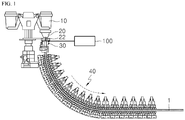
- Figure 1 is a schematic view of a casting equipment according to an embodiment of the present disclosure
- Figure 2 shows a main configuration of the casting equipment shown in Figure 1
- Figure 3 is a block diagram showing the configuration of the casting equipment shown in Figure 2 .
- a casting equipment may include a ladle 10 configured for receiving molten steel refined in a steelmaking process therein; a tundish 20 configured for receiving the molten steel through an injecting nozzle (unshown) connected to the ladle 10, storing the molten steel therein temporarily and supplying it to a mold 30; the mold 30 configured for receiving the molten steel through a submerged nozzle 22 connected to the tundish 20 and initially solidifying it in a uniform shape; a cooling line 40 disposed below the mold 30 and having a plurality of segments continuously arranged for performing a series of molding operations while cooling an unsolidified slab 1 drawn from the mold 30.
- the casting equipment may include a device 100 for injecting molten material, wherein the device 100 is configured for melting and supplying a mold flux onto a top face of the molten steel to be supplied to the mold 30; a measuring unit 130 configured for measuring various component changes resulted from a change in a component of the mold flux in the mold 30; a control unit 140 configured for controlling an operation of the device 100 for injecting the molten material based on a measured result from the measuring unit 130.
- the device 100 for injecting the molten material may melt a solid mold flux and supply a liquid mold flux i.e. molten mold flux, to the mold 30.
- a liquid mold flux i.e. molten mold flux
- the device for injecting the molten material melted a mold flux provided to have a certain component suitable for a steel grade as it is by a heating means such as a plasma torch and supplied to the mold 30 simultaneously.
- a heating means such as a plasma torch
- the device 100 for injecting the molten material is configured to change the molten mold flux component supplied to the mold 30 in real time in the present disclosure.
- the term "mold flux” refers to a solid mold flux when before being supplied to the smelting furnace 112, and then when after the solid mold flux being melted in the smelting furnace 112, it is referred as the "molten mold flux”.
- molten mold flux when after the molten mold flux is injected into the mold 30, it is referred as "mold slag".
- the device 100 for injecting the molten material may include: a raw material supply unit 110 configured for supplying the solid mold flux; a melting unit 120 configured for receiving and melting the solid mold flux to generate the molten mold flux, and injecting the molten mold flux into the mold 30; and the control unit 140 configured for controlling an operation of the raw material supply unit 110 and the melting unit 120.
- the raw material supply unit 110 may include: a first raw material supply unit 112 configured for supplying a first raw material; a second raw material supply unit 112 configured for supplying a second raw material; and a mixing unit 116 connected to the first raw material supply unit 112 and the second raw material supply unit 114, and configured for mixing a first raw material and a second raw material respectively supplied from the first raw material supply unit 112 and the second raw material supply unit 114.
- the raw material supply unit 110 may supply the mixture of the first raw material and the second material to the melting unit 120 through the mixing unit 116, but a raw material feeding unit 118 may be disposed between the mixing unit 116 and the melting unit 120 to supply the first raw material or the mixture of the first raw material and the second raw material uniformly to the melting unit 120.
- the first raw material supply unit 112 may include: a first storage unit 112a configured for storing the first raw material, such as a main mold flux therein; and a first transfer pipe 112b for communicating the first storage unit 112a and the mixing unit 116.
- the first storage unit 112a stores the solid first raw material e.g. the main mold flux therein.
- a first feeder 112c may be disposed at a portion where the main mold flux is discharged from the first storage unit 112a or at the first transfer pipe 112b to discharge the main mold flux by a predetermined amount or uniformly.
- the first feeder 112c may be a screw feeder provided at the first storage unit 112a or the first transfer pipe 112b and operated by an operation of a driving device, or may be a valve that opens or closes a connection of the first storage unit 112a and the first transfer pipe 112b or a flow path inside the first transfer pipe 112b.
- the second raw material supply unit 114 may include a second storage unit 114a for storing the second raw material, such as an additive therein, and a second transfer pipe 114b for communicating the second storage unit 114a and the mixing unit 116.
- the plurality of second storage units 114a may be provided so that various types of the additive may be independently stored therein.
- a second feeder 114c may be provided at a portion of the second storage unit 114a from which the additive is discharged or at the second transfer pipe 114b to discharge the additive to the mixing unit 116 by a predetermined amount or uniformly.
- the second feeder 114c may be a screw feeder connected to the second storage unit 114a or the second transfer pipe 114b and operated by the operation of the driving device or may be a valve that opens or closes a connection of the second storage unit 114a and the second transfer pipe 114b or a flow path inside the second transfer pipe 114b.
- the second raw material supply unit 114 may selectively supply at least one of the plurality of additives.
- the mixing unit 116 may supply a mold flux uniformly mixed of the main mold flux and the additive respectively from the first raw material supply unit 112 and the second raw material supply unit 114 to the melting unit 120.
- the mixing unit 116 may also supply only the first raw material from the first raw material supply unit 112 to the melting unit 120.
- the mixing unit 116 may include: a mixing vessel 116a configured for receiving the main mold flux and the additive respectively supplied from the first raw material supply unit 112 and the second raw material supply unit 114 therein; an agitator (not shown) configured for uniformly mixing the main mold flux and the additive received in the mixing vessel 116a; and a third transfer pipe 116b configured for transferring the mixture of the main mold flux and the additive, that is, the mold flux, to the melting unit 120.
- the mixing vessel 116a may receive solid main mold flux and additive discharged from the first raw material supply unit 112 and the second raw material supply unit 114 therein.
- a third feeder 116c may be disposed at a portion from which the mixture of the main mold flux and the additive is discharged or at the third transfer pipe 116b to discharge the mixture of the first raw material and the second raw material by a predetermined amount or uniformly.
- the third feeder 116c may be a screw feeder provided at the mixing vessel 116a or the third transfer pipe 116b and operated by the operation of the driving device or may be a valve that opens or closes a connection of the mixing vessel 116a and the third transfer pipe 116b or a flow path inside the third transfer pipe 116b.
- the agitator may be formed of a screw or an impeller configured to be rotatable in the mixing vessel 116a.
- the agitator may be formed of a nozzle capable of blowing inert gas and the like into the mixing vessel 116a.
- the mixing unit 116 includes the mixing vessel 116a and the agitator.
- the mixing vessel 116a may be configured to be rotatable to uniformly mix the main mold flux and the additive without the agitator.
- the mixing unit 116 may not limited thereto and formed in various shapes to uniformly mix the main mold flux and the additive.
- the mixing unit 116 may also include a heater 116d configured for preheating the main mold flux or the mixture of the main mold flux and the additive.
- the heater 116d may be provided at the agitator or the mixing vessel.
- the main mold flux or the mixture of the main mold flux or the additive may be heated at a predetermined temperature and supplied to the raw material feeding unit 118.
- the raw material feeding unit 118 may include: a third storage unit 118a for communicating with the third transfer pipe 116b of the mixing unit 116; a fourth transfer pipe 118b configured for connecting the third storage unit 118a to the melting unit 120 and supplying the first raw material or the mixture of the first raw material and the second raw material through an internal flow path thereof; and a fourth feeder 118c may be provided to connect the third storage unit 118a and the fourth transfer pipe 118b to supply the first raw material or the mixture of the first raw material and the second raw material to the melting unit 120 by a predetermined amount or uniformly.
- the fourth feeder 118c may be a screw feeder or a valve that is connected to the third storage unit 118a and the fourth transfer pipe 118b like as above-mentioned first to third feeders 112c, 114c, and 116c.
- the raw material feeding unit 118 may also include a heater 118d for preheating the main mold flux or the mixture of the main mold flux and the additive supplied from the mixing unit 116.
- the heater 118d may be disposed at the third storage unit 118a or the fourth transfer pipe 118b.
- the heater 118d may heat the main mold flux or the mixture of the main mold flux and the additive at a predetermined temperature and supply to the melting unit 120. Therefore, by accelerating the melting of the main mold flux or the mixture of the main mold flux and the additive, it may be possible to respond more rapidly to the change of the component of the mold slag.
- the melting unit 120 may generate and temporarily store molten mold flux by heating and melting the mold flux, that is the mixture of the main mold flux and the additive supplied from the mixing unit 116, and discharge the molten mold flux and inject it into the mold 30.
- the melting unit 120 may include: the smelting furnace 112 configured for receiving the mixture supplied from the mixing unit 116 therein; a heat source supply unit 128 configured for supplying a heat source inside the smelting furnace 112.
- a smelting space where the main mold flux and the additive are injected and melted may be defined inside of the smelting furnace 112, and a discharge port 126 for injecting the molten mold flux to the mold 30 may be defined at one side of the smelting furnace 112.
- the smelting furnace 112 may be formed in an approximately "V" shaped with downwardly bent center portion and may be provided in a tilted manner.
- the smelting furnace 112 may include an injection port 124 for injecting the mold flux discharged from the mixing unit 116 into the smelting space at an upper side thereof and the discharge port 126 for injecting the molten mold flux generated in the smelting space into the mold 30.
- the heat source supply unit 128 may be connected to one side of the smelting furnace 112 so as to supply the heat source to the smelting space.
- the heat source from the one side of the smelting furnace 112 may be supplied, the mold flux in the smelting space may be melted so that the molten mold flux may be generated and temporarily stored therein and through the discharge port 126 at the other side thereof, the molten mold flux may be discharged and injected into the mold 30. This is possible because the smelting furnace 112 is provided in the tilted manner.
- a discharging amount of the molten mold flux may be regulated based on a degree of tilting of the smelting furnace 112.
- the heat source supply unit 128 may include a plasma torch and a gas supply pipe that supplies plasma gas such as nitrogen (N 2 ), argon (Ar), helium (He), etc. with the plasma torch.
- the plasma torch is a device for generating plasma of a high temperature of 20,000 °C or above using electricity, and generates the plasma to the smelting space of the smelting furnace 112.
- the plasma torch may include: a plasma confinement tube for receiving a plasma gas supplied from the gas supply pipe; an induction coil disposed to surround the plasma confinement tube; and a power supply unit for supplying power to the induction coil. Thus, when the power from the power supply unit is applied to the induction coil, the plasma is generated inside the plasma confinement tube.
- Plasma thus generated and heat induced by the plasma may be used as a heat source to melt the mixture, i.e. the solid mold flux and the additive supplied to the smelting space through the injection port 124.
- the molten mold flux in the smelting space may be temporarily stored therein, and when the smelting furnace 112 is tilted, it may be discharged from the discharge port 126 and injected into the mold 30.
- the smelting furnace 112 constituting the melting unit 120 may be formed in various shapes, and the molten mold flux may also be discharged by various ways.
- Such a melting unit 120 is a well-known technology, therefore a detailed description thereof will be omitted.
- the device 100 for injecting the molten material may control and melt the component of the mold flux in real time and inject into the mold 30.
- the measuring unit 130 may be disposed at the mold 30.
- the measuring unit 130 may include a thermometer for measuring a heat transferring behavior of the mold 30, or a probe for measuring the component of the mold flux injected into the mold 30.
- the thermometer When the thermometer is used as the measuring unit 130, the thermometer may be installed at the mold 30 to measure a temperature change of the mold 30. For example, when in case of multiple continuous-castings of the single steel grade, the viscosity of the mold slag is increased due to an introduction of Al 2 O 3 into the mold slag after a certain period of time. Thus, the mold slag is ununiformly introduced between the mold 30 and the solidified shell, and a lubrication is not properly performed.
- a heat transfer from the solidified shell to the mold 30 is not uniform, resulting in a variation in a temperature value measured by the thermometer. Therefore, a casting performance may be improved by changing the component of the molten mold flux to be injected into the mold 30 based on the temperature value measured by the thermometer.
- the probe When the probe is used as the measuring unit 130, a portion of the mold slag in the mold 30 is sampled. Then, by analyzing the components of the mod slag collected from the probe, the components of the molten mold flux injected into the mold 30 and the mold slag may be compared and analyzed. In response to the change of the component of the mold slag during casting, the casting performance may be improved by changing the component of the molten mold flux to be injected into the mold 30 in the future.
- the control unit 140 may receive the measurement of the measuring unit 130. Based on the measurement of the measurement, the control unit 140 may control the operation of the raw material supply unit and control the component of the molten mold flux to be injected into the mold 30. As a result, supply amounts of the main mold flux and the additive may be controlled. In addition, the control unit 140 controls the operation of the melting unit 120 and the measuring unit 130, thereby controlling supply amount of the molten mold flux to be injected into the mold 30 based on the measurement.
- the casting method according to the present disclosure may include a first embodiment for casting a slab using a single steel grade and a second embodiment for casting a slab using two grades of the steel.
- Figure 4 is a sequence diagram showing the casting method according to the first embodiment of the present disclosure.
- the casting method may include: a step S110 of preparing the main mold flux and the additive; a step S120 of injecting the molten steel passed through the ladle 10 and the tundish 20 into a mold 30; a step S130 for injecting the molten mold flux to a top face of the molten steel injected into the mold 30; a step S140 for measuring the casting state; and a step S150 for analyzing the casting state and determining whether or not to input the additive; and a step S160 for inputting the additive. Injecting the molten steel and the molten mold flux into the mold 30 may be performed continuously during casting. Further, by a step S170 of determining whether the casting is completed, measuring the casting state and inputting the additive may be repeatedly performed during casting.
- the molten mold flux injected into the mold 30 at beginning of the casting is called a first molten mold flux
- the molten mold flux mixed with the additive during the casting and injected into the mold 30 is called a second molten mold flux.
- the solid main mold flux is provided into the first storage unit 112a, and the additive to be mixed with the main mold flux during the casting is provided into the second storage unit 114a.
- the molten mold flux may include CaO, SiO 2 , MnO, P 2 O 5 , Al 2 O 3 , MgO, TiO 2 , K 2 O, Na 2 O, F, Fe 2 O 3 and the like.
- the main mold flux may be prepared to have a composition suitable for the molten steel to be used in the casting.
- the additive may be one or a mixture of at least two components selected from a group consisting of NaF(s), Na 3 AlF 6 , CaF 2 (s), AlF 3 (s), SiO 2 (s), Li 2 O(s), LiF(s), CaO, MnO, P 2 O 5 , MgO, Al 2 O 3 (s), TiO 2 , Fe 2 O 3 , K 2 O(s), Na 2 O(s).
- a refining process is completed and the molten steel received in the ladle 10 is supplied to the tundish 20 through the injecting nozzle, and the molten steel supplied to the tundish 20 is injected into the mold 30 through the submerged nozzle 22 provided at the tundish 20.
- the first molten mold flux is injected to the top face of the molten steel in the mold 30.
- the main mold flux is transferred from the first storage unit 112 where it is firstly stored to the melting unit 120 through the mixing vessel 116a of the mixing unit 116.
- the first molten mold flux may be produced by melting said main mold flux in the melting unit 120.
- the first molten mold flux injected at the beginning of the casting may be produced by melting only the main mold flux in the melting unit 120.
- the slab may be casted by injecting the molten steel and the first molten mold flux into the mold 30.
- the mold slag maintains its components when injected, but as the casting progresses, the impurities in the molten steel flow into the mold slag and the components of the mold slag change.
- the viscosity of the mold slag increases. In this case, the mold slag does not inflow smoothly between the mold 30 and the solidified shell, and the mold slag is unevenly introduced in the width direction and the longitudinal direction of the mold 30.
- a quality of the slab may be improved by allowing the mold slag to inflow uniformly between the mold and the solidified shell in response to the component change of the mold slag.
- Whether or not to inject the additive may be determined based on the casting state, for example, the temperature change of the mold 30 or the change of the component of the mold slag.
- the temperature of mold 30 may be measured by installing a plurality of thermometers in the longitudinal direction and the width direction of the mold 30 and measuring the temperature value in the longitudinal direction and(or) the width direction of the mold 30. Then, the deviation of the measured temperature value from the thermometer may be measured. When the measured temperature value falls within a deviation range of about 0% to 5% from the initial measured temperature value, the casting may proceed as it is. Or when the measured temperature value deviates from above-stated deviation range, the additive may be determined to be injected.
- the measured temperature value is within the deviation range, it is determined that the mold slag is being uniformly injected between the mold 30 and the solidified shell, and the component change of the mold slag is insignificant, thus the molten mold flux of the same component as the initial casting, i.e. the first molten mold flux is injected into the mold 30.
- the molten mold flux into which the additive is injected i.e. the second molten mold flux may be injected into the mold 30.
- the additive to be injected into the mold 30 may be selected as follows.
- the temperature value measured from the thermometer changes within a certain range because there is little change in the component of the mold slag.
- the impurities in the molten steel flow into the mold slag, causing a change in the component of the mold slag.
- Al 2 O 3 in the molten steel may inflow, or fluorine (F) component in the mold slag may volatilize, resulting in a higher viscosity of the mold slag.
- F fluorine
- the mold flux and the additive by mixing the mold flux and the additive and melting and injecting the mixture into the mold 30, thereby suppressing or preventing a deterioration of casting efficiency resulted from the component change of the mold slag.
- a large amount of Al 2 O 3 is introduced into the mold slag, at least one of NaF, CaF 2 , and Li 2 CO 3 may be used as the additive, and when fluorine in the mold slag is volatilized, Na 3 AlF 6 or NaF and the like may be used as the additive. Because of this, the viscosity of the mold slag in the mold 30 may be reduced to some extent, so that the mold slag may be uniformly injected between the mold 30 and the solidified shell.
- Na 3 AlF 6 as the additive may be inputted at 50 g/min. That is, the additive may be inputted in a range of 1 to 5% by weight of the molten mold slag.
- the fluorine content of the component in the mold slag injected into the mold 30 is increased up to about 2.7 wt%, and the viscosity of the mold slag is increased, thereby smooth inflow of the mold slag between the mold and the solidified shell.
- Al 2 O 3 and Na 2 O components also somewhat increased within a range of more than 0 to 2 wt%. The change of the Al 2 O 3 and Na 2 O contents is not so much compared to the change of the fluorine content, thus it does not affect the casting much.
- additives described above may be used as the additive.
- the control unit 140 receives the measurement from the measuring unit 130, for example, the thermometer, and controls the operations of the first feeder 112c of the first raw material supply unit 112 and the second feeder 114c of the second raw material supply unit 114. Then, the main mold flux and the additive respectively stored in the first storage unit 112a and the second storage unit 114a are supplied into the mixing vessel 116a of the mixing unit 116.
- control unit 140 operates the agitator of the mixing unit 116 to uniformly mix the main mold flux and the additive supplied to the mixing vessel 116a.
- control unit 140 operates the third feeder 116c of the mixing unit 116 to inject the mixture of the main mold flux and the additive into the smelting furnace 112 of the melting unit 120.
- the mixture injected into the smelting furnace 112 is melted by the heat supplied from the heat source supply unit 128 of the melting unit 120, that is, the plasma, to be produced as the second molten mold flux.
- the second molten mold flux thus produced is injected into the mold 30 through the discharge port 126 formed at the smelting furnace 112 by the inclination of the smelting furnace 112 and mixed with the mold slag.
- the viscosity of the mold slag in the mold 30 is lowered, allowing the uniform inflow between the mold 30 and the solidified shell.
- the quality of the slab may be improved by rapidly responding to the temperature change of the mold 30 resulting from the component change of the mold slag.
- Control of the component of the mold slag during the casting may be repeated many times, depending on the measurement from the measuring unit 130. Therefore, since the component of the mold slag may be rapidly controlled in response to the component change of the mold slag during the casting, unless deterioration of the device such as the submerged nozzle 22 and the like occurs, the number of the charge may be increased to prolong the casting time, and the continuous continuous-casting becomes possible, which may improve a throughput of the molten steel, that is a production amount of the slab.
- the component change of the mold slag is measured based on the temperature change of the mold 30.
- the component of the mold slag may be analyzed by collecting the mold slag during the casting.
- the component change of the mold slag may be measured visually.
- Figure 5 is a block diagram conceptually showing a method of injecting the molten mold flux into the mold when the slab is casted according to a second embodiment of the present disclosure.
- the second embodiment of the present disclosure describes a method of casting different steel grades, such as the two grades of the steel.
- mold fluxes with different components are used.
- the mold flux to be used includes CaO, SiO 2 , MnO, P 2 O 5 , Al 2 O 3 , MgO, TiO 2 , K 2 O, Na 2 O, F, Fe 2 O 3 and the like, but there is a difference in contents thereof, and other components may be further included. Therefore, when continuously casting these two grades of the steel, different mold fluxes are injected as the steel grade changes. In this case, suitable mold flux based on the steel grade should be provided separately.
- the component of the molten mold flux may be controlled based on the steel grade used in the casting and injected into the mold 30.
- a mold flux applicable to all steel grades is called a main mold flux
- an additive used at the beginning of the casting is called a first additive
- an additive used when the steel grade is changed during the casting is called a second additive
- an additive used based on the results measured by the measuring unit 130 during the casting is called a third additive.
- the casting method according to the second embodiment of the present disclosure may include: preparing the main mold flux and the first additive, the second additive and the third additive; injecting a first molten steel passed through the ladle 10 and the tundish 20 into the mold 30; injecting a first molten mold flux prepared by mixing the main mold flux and the first additive to the top face of the first molten steel injected into the mold 30; injecting a second molten steel into the mold 30 when after the casting using the first molten steel is completed; and injecting a second molten mold flux, prepared using the main mold flux and the second additive, to the top face of the second molten steel injected into the mold 30.
- measuring the casting state and injecting the third additive based on the casting state may be included.
- the casting using the first molten steel and the casting using the second molten steel may be performed sequentially, measuring the casting state and injecting the third additive may be repeatedly performed during the casting by determining the completion of the casting using the second molten steel.
- the main mold flux applicable to all steel grades, the first additive for controlling the component of the mold flux based on the steel grade, the second additive for controlling the component of the mold slag during the casting are prepared.
- the main mold flux may include CaO, SiO 2 , MnO, P 2 O 5 , Al 2 O 3 , MgO, TiO 2 , K 2 O, Na 2 O, F, Fe 2 O 3 and the like.
- the third additive may be at least one selected from a group consisting of NaF(s), Na 3 AlF 6 , CaF 2 (s), AlF 3 (s), SiO 2 (s), Li 2 O(s), LiF(s), CaO, MnO, P 2 O 5 , MgO, Al 2 O 3 (s), TiO 2 , Fe 2 O 3 , K 2 O(s), Na 2 O(s), C.
- the first additive and the second additive are prepared for control the component of the mold flux based on the steel grade, may include at least one of the components of the main mold flux and may include at least one of the components of the second additive.
- the first additive and the second additive may be at least one of CaO, SiO 2 , MnO, P 2 O 5 , Al 2 O 3 , MgO, TiO 2 , K 2 O, Na 2 O, F, Fe 2 O 3 , NaF S, Na 3 AlF 6 , CaF 2 (s), AlF 3 (s), SiO 2 (s), Li 2 O(s), LiF(s), CaO, MnO, P 2 O 5 , MgO, Al 2 O 3 (s), TiO 2 , Fe 2 O 3 , K 2 O(s), Na 2 O(s), C.
- the first additive and the second additive may be the same component.
- the main mold flux thus prepared may be stored in the first storage unit 112a of the first raw material storage unit, and the first additive, the second additive and the third additive may be stored in the second storage unit 114a of the second raw material storage unit.
- the second storage unit 114a may be provided in a plurality, and may store each of the components of the first additive, the second additive, and the third additive.
- the first molten steel is injected into the mold 30, and the first molten mold flux, which is produced by mixing the main mold flux and the first additive is injected to the top face of the first molten steel.
- the second molten steel is injected into the mold 30, and the second molten mold flux, which is produced by mixing the main mold flux and the second additive is injected to the top face of the second molten steel.
- the first molten mold flux and the second molten mold flux have different Al 2 O 3 contents. That is, the first molten mold flux contains less Al 2 O 3 than the second molten mold flux.
- the first molten steel is injected into the mold 30 at the beginning of the casting, a small amount, for example less than 1 % of the Al 2 O 3 is injected into the main mold flux and the first additive.
- 1 to 3 % of the Al 2 O 3 may be inputted to the main mold flux and second additive.
- the second additive may be injected in a gradual manner so that the second molten mold flux has a suitable physical property for the second molten steel. This is because when the physical property of the second molten mold flux, such as the viscosity or a basicity is changed suddenly, the second molten mold flux may not inflow smoothly between the mold and the solidified shell, thus slab break-out may occur.
- the first additive and the second additive being composed of the same component, and increasing the amount of the input thereof was described.
- the input amount of the first additive and the second additive may be gradually reduced, and the components of the first additive and the second additive may be different.
- the method of casting using two grades of the molten steel has been described, it is also possible to cast using two or more grades of the molten steel.
- the casting state may be measured as in the above-described embodiment, and the second additive may be used to control the component of the mold slag based on the measurement.
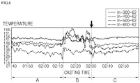
- Figure 6 is a graph showing experimental results based on whether the additive inputted when the slab is casted according to the casting method of the embodiment of the present disclosure.
- Figure 6 shows the temperature change of the mold depending on whether the additive is inputted during the casting.
- thermometers were installed at the mold 30, and the temperature of the mold 30 during the casting was measured.
- the thermometer was installed at a plurality of points along the width direction of the mold 30, for example, from a widthwise center of the slab to the longitudinal direction of the mold 30, for example, a casting direction of the slab, specifically at 300, 400, 500 and 600 mm from the top of the mold 30.
- the molten steel was injected into the mold 30, and the first molten mold flux which melted the main mold flux was injected to the top face of the molten steel injected into the mold 30.
- Figure 6 shows that the temperature of the mold 30 changes within a certain range at a beginning of the casting (section A). However, in a middle of the casting (section B), the temperature of the mold 30 changes sharply and fluctuates irregularly. The temperature of the mold 30 was observed for a certain period of time, but it did not return to the same pattern as the beginning of the casting (period A).
- the second molten mold flux which was produced by mixing and melting the main mold flux and the additive, was injected into mold 30.
- the fluorine F was injected as the additive.
- This phenomenon may be caused by the change of the component of the mold slag through the reaction with the impurities in the molten steel during the casting. Therefore, it is possible to smoothly perform casting by controlling the component of the mold slag by injecting the additive during the casting, thereby suppressing or preventing the slab quality deterioration.
- the present disclosure is not limited thereto and may be applied to various operations such as a refining process using an aqueous dephosphorization agent.
- the device for injecting the molten material, the casting equipment using the same, and the casting method according to the present disclosure may be applied to the continuous slab casting process to improve the quality and productivity of the slab.
Landscapes
- Engineering & Computer Science (AREA)
- Mechanical Engineering (AREA)
- Continuous Casting (AREA)
Abstract
Description
- The present disclosure relates to a device for injecting molten material, a casting equipment using the same, and a casting method. More specifically, the present disclosure relates to a device for injecting molten material able to improve a quality and productivity of a slab, a casting equipment using the same, and a casting method.
- A device for injecting molten material, for example a device for injecting molten mold flux used in a slab casting process, is an equipment that melts the mold flux in powder and supplies it to a mold. Typical molten mold flux injecting equipment includes a hopper configured for storing the mold flux therein, a smelting furnace configured for receiving the mold flux from the hopper and melting it, and a torch disposed at one side of the smelting furnace and configured for melting the mold flux by spraying a flame into the smelting furnace. In this connection, at the smelting furnace, a discharge port configured for discharging the molten mold flux may be defined.
- Thus, when the mold flux is melted and supplied to the mold, a temperature drop of molten steel in the mold may be suppressed, and at the same time a lubricating ability may be improved to reduce a defect of the slab.
- However, when a slab is casted by melting a mold flux produced to have a certain component for each steel grade, the component of the mold flux changes due to a reaction between impurities contained in the steel and the mold flux. For example, when a slab is casted using molten steel containing a large amount of Al, as Al2O3 is picked up in the mold flux, a viscosity of the mold flux is increased.
- Thus, the mold flux does not inflow smoothly between the mold and the slab (solidified shell), therefore a heat transfer between the molten steel and the mold becomes uneven and the lubricating ability decreases. Thus, an operation accident such as a solidified shell break-out or a crack on a surface of the slab occurs.
- Such change in the components of the mold flux may lead to difficulty in carrying out multiple continuous-castings of a single steel grade at least one charge.
- On the other hand, in case of multiple continuous-castings of two grades of steel, change in the grade of the steel may requires a mold flux suitable for the changed grade. Therefore, when the steel grade is changed, the mold flux produced so as to have a suitable component for the changed grade should be injected into the mold. However, when supplying the mold flux suitable for the steel grade, it is preferable mold fluxes having different components not to be mixed with each other, but due to an operation property, a transient phenomenon in which the mold fluxes having different components are mixed with each other is inevitable. In such the transient phenomenon, the mold flux does not inflow smoothly between the mold and the solidified shell, so that the solidified shell sometimes breaks out.
- The present disclosure provides a device for injecting molten material which is able to improve a casting efficiency, a casting equipment using the same, and a casting method.
- The present disclosure provides a device for injecting molten material which is able to improve a quality of a slab, a casting equipment using the same, and a casting method.
- A device for injecting molten material according to an embodiment of the present disclosure, the device may comprise: raw material supply units configured for supplying different first and second raw materials respectively; a mixing unit configured for mixing the different first and second raw materials supplied from the raw material supply units to produce a mixture; a melting unit connected to the mixing unit to melt the mixture supplied from the mixing unit to produce molten material, and the melting unit has a discharge port through which the molten material is discharged; and a control unit configured for controlling a component of the mixture by controlling operations of the raw material supply units, mixing unit and melting unit.
- The raw material supply unit may include: a first raw material supply unit configured for supplying a first raw material; and second raw material supply units configured for respectively supplying a plurality of second raw materials containing different components.
- The first raw material supply unit may include: a first storage unit configured for storing the first raw material therein; a first transfer pipe for communicating the first storage unit and the mixing unit; and a first feeder coupled to at least one of the first storage unit and the first transfer pipe to regulate a discharge amount of the first raw material.
- Each of the second raw material supply unit may include: a second storage unit configured for storing each of the plurality of second raw materials therein; a second transfer pipe configured for communicating each of the plurality of second storage units and the mixing unit; and a second feeder coupled to at least one of the second storage unit and the second transfer pipe to regulate a discharge amount of each of the second raw material.
- The mixing unit may include: a mixing vessel in communication with the first supply pipe and the second supply pipe; an agitator disposed in the mixing vessel for mixing the first raw material and the second raw material; and a third transfer pipe for transferring the mixture of the first raw material and the second material to the melting unit.
- The mixing unit may include a mixing vessel in communication with the first supply pipe and the second supply pipe, and the mixing vessel is rotatable.
- The melting unit may include: a smelting furnace having a smelting space defined therein for receiving the first raw material and the second raw material therein; a heat source supply unit disposed at one side of the smelting furnace to supply a heat source to the smelting space.
- The heat source supply unit uses plasma as the heat source.
- The control unit may be configured to determine whether or not to inject the second raw material based on an input signal.
- A casting equipment may comprise: a mold for receiving and initially solidifying molten steel; a device for injecting molten mold flux into the mold; a measuring unit configured for measuring temperatures of at least one of a temperature of the mold and a component of the molten mold flux injected into the mold; and a control unit configured for controlling an operation of the device based on a measurement from the measuring unit to change the component of the molten mold flux to be injected into the mold.
- The device may include: a first raw material supply unit configured for supplying main mold flux; second raw material supply units configured for supplying additives; a mixing unit configured for mixing the main mold flux and the additives respectively supplied from the first raw material supply unit and the second raw material supply units, thereby to produce a mixture; and a melting unit configured for melting the mixture supplied from the mixing unit to produce molten mold flux, and for injecting the molten mold flux into the mold.
- The second raw material supply units may store therein the plurality of additives individually, and the second supply units feed selectively the plurality of additives to the mixing unit.
- The measuring unit may include a thermometer configured for measuring a temperature of the mold.
- The measuring unit may include: a probe configured for collecting molten mold flux injected into the mold; an analyzing unit configured for analyzing a component of the molten mold flux collected by the probe.
- The control unit may be configured to determine whether to input the additives using a measurement from the measuring unit, and to control types and input amounts of the additives by controlling the second raw material supply units based on the measurement.
- A casting method may comprise: preparing main mod flux; injecting molten steel into a mold; melting the main mold flux to produce molten mold flux and injecting the molten mold flux onto a top face of the molten steel; casting a slab; and determining whether to input an additive based on a casted state of the slab during casting thereof.
- In preparing of the main mold flux, the additive may be prepared.
- During melting the main mold flux to produce the molten mold flux, the main mold flux and the additive may be melted together.
- In casting the slab, a temperature of the mold may be measured to indicate the casted state of the slab, and the method may include determining whether to input the additive based on the measured temperature of the mold.
- In casting the slab, a component of the molten mold flux injected into the mold may be analyzed to indicate the casted state of the slab, the method may include determining whether to input the additive based on the analyzed component of the molten mold flux.
- The method may include, upon determination that the additive is added, mixing the main mold flux and the additive to form a mixture, and melting the mixture, and injecting molten mold flux containing a changed component into the mold.
- The method may include, when, in casting the slab, a grade of molten steel to be injected into the mold has been changed, mixing the main mold flux and the additive, melting the mixture, and injecting molten mold flux containing a changed component into the mold.
- When the main mold flux and the additive are mixed, components of the additives as injected may vary depending on the grades of the molten steel.
- When the main mold flux and the additive are mixed, injection amounts of the additives containing the same component may vary depending on the grades of the molten steel.
- According to embodiments of the present disclosure, casting efficiency and slab quality may be improved by rapidly responding to the component changes in the mold slag during the casting.
- In other words, by adding an additive to control the component of the mold slag during the casting, it may cope with the component change of the mold slag in real time.
- Therefore, it is possible to prevent slab surface cracking or solidified shell breaking-out resulted from the component change of the mold slag, which may improve the quality of the slab.
- In addition, continuous-continuous castings of a single steel grade is possible and productivity may be improved.
- In addition, the casting efficiency may be improved by rapidly producing and supplying the molten mold flux suitable for the steel grade in continuous-continuous casting of various steel grades.
- Therefore, it is possible to suppress or prevent occurrence of the slab breaking-out phenomenon by reducing a mixing time of molten mold fluxes having different physical properties.
-
-
Figure 1 is a schematic view of a casting equipment according to an embodiment of the present disclosure. -
Figure 2 shows a main configuration of the casting equipment shown inFigure 1 . -
Figure 3 is a block diagram showing the configuration of the casting equipment shown inFigure 2 . -
Figure 4 is a sequence diagram showing a casting method according to a first embodiment of the present disclosure. -
Figure 5 is a block diagram conceptually showing a method of injecting molten mold flux into a mold when a slab is casted according to a second embodiment of the present disclosure. -
Figure 6 is a graph showing experimental results based on whether an additive inputted when a slab is casted according to a casting method of the embodiment of the present disclosure. - Hereinafter, an embodiment of the present disclosure will now be described in detail with reference to the accompanying drawings. The present disclosure may, however, be embodied in many different forms and should not be construed as limited to the embodiments set forth herein, rather, these embodiments are provided by way of illustration only and so that this disclosure will be thorough, complete and will fully convey the full scope of the invention to those skilled in the art.
-
Figure 1 is a schematic view of a casting equipment according to an embodiment of the present disclosure,Figure 2 shows a main configuration of the casting equipment shown inFigure 1 , andFigure 3 is a block diagram showing the configuration of the casting equipment shown inFigure 2 . - Referring to
Figure 1 , a casting equipment according to an embodiment of the present disclosure may include aladle 10 configured for receiving molten steel refined in a steelmaking process therein; a tundish 20 configured for receiving the molten steel through an injecting nozzle (unshown) connected to theladle 10, storing the molten steel therein temporarily and supplying it to amold 30; themold 30 configured for receiving the molten steel through a submergednozzle 22 connected to the tundish 20 and initially solidifying it in a uniform shape; acooling line 40 disposed below themold 30 and having a plurality of segments continuously arranged for performing a series of molding operations while cooling an unsolidified slab 1 drawn from themold 30. - Further, referring to
Figure 2 and3 , the casting equipment may include adevice 100 for injecting molten material, wherein thedevice 100 is configured for melting and supplying a mold flux onto a top face of the molten steel to be supplied to themold 30; ameasuring unit 130 configured for measuring various component changes resulted from a change in a component of the mold flux in themold 30; acontrol unit 140 configured for controlling an operation of thedevice 100 for injecting the molten material based on a measured result from themeasuring unit 130. - The
device 100 for injecting the molten material may melt a solid mold flux and supply a liquid mold flux i.e. molten mold flux, to themold 30. Conventionally, the device for injecting the molten material melted a mold flux provided to have a certain component suitable for a steel grade as it is by a heating means such as a plasma torch and supplied to themold 30 simultaneously. However, although the molten mold flux supplied into themold 30 during casting reacts with impurities in the molten steel to change its component, the device for injecting the molten material continuously supplies the mold flux of the same component, therefore it was impossible to cope with the component change in real time. - In addition, when in case of continuous-continuous-castings of different steel grades, mold fluxes having different components suitable for the steel grades provided. Thus, it is time consuming to change the mold flux to a mold flux having a component suitable for the steel grade, and mold fluxes of different components are inevitably mixed to each other in a
smelting furnace 112. Result from the mixing of the mold fluxes, the mold flux does not inflow smoothly between themold 30 and a solidified shell, so that a problem such as a solidified shell break-out occurred. - Therefore, in order to solve the above-mentioned problem of the device for injecting the molten material, the
device 100 for injecting the molten material is configured to change the molten mold flux component supplied to themold 30 in real time in the present disclosure. Hereinafter, the term "mold flux" refers to a solid mold flux when before being supplied to thesmelting furnace 112, and then when after the solid mold flux being melted in thesmelting furnace 112, it is referred as the "molten mold flux". In addition, when after the molten mold flux is injected into themold 30, it is referred as "mold slag". - The
device 100 for injecting the molten material according to an embodiment of the present disclosure may include: a rawmaterial supply unit 110 configured for supplying the solid mold flux; amelting unit 120 configured for receiving and melting the solid mold flux to generate the molten mold flux, and injecting the molten mold flux into themold 30; and thecontrol unit 140 configured for controlling an operation of the rawmaterial supply unit 110 and themelting unit 120. - The raw
material supply unit 110 may include: a first rawmaterial supply unit 112 configured for supplying a first raw material; a second rawmaterial supply unit 112 configured for supplying a second raw material; and amixing unit 116 connected to the first rawmaterial supply unit 112 and the second rawmaterial supply unit 114, and configured for mixing a first raw material and a second raw material respectively supplied from the first rawmaterial supply unit 112 and the second rawmaterial supply unit 114. - In addition, the raw
material supply unit 110 may supply the mixture of the first raw material and the second material to themelting unit 120 through themixing unit 116, but a rawmaterial feeding unit 118 may be disposed between the mixingunit 116 and themelting unit 120 to supply the first raw material or the mixture of the first raw material and the second raw material uniformly to themelting unit 120. - The first raw
material supply unit 112 may include: afirst storage unit 112a configured for storing the first raw material, such as a main mold flux therein; and afirst transfer pipe 112b for communicating thefirst storage unit 112a and themixing unit 116. - The
first storage unit 112a stores the solid first raw material e.g. the main mold flux therein. Afirst feeder 112c may be disposed at a portion where the main mold flux is discharged from thefirst storage unit 112a or at thefirst transfer pipe 112b to discharge the main mold flux by a predetermined amount or uniformly. In this connection, thefirst feeder 112c may be a screw feeder provided at thefirst storage unit 112a or thefirst transfer pipe 112b and operated by an operation of a driving device, or may be a valve that opens or closes a connection of thefirst storage unit 112a and thefirst transfer pipe 112b or a flow path inside thefirst transfer pipe 112b. - The second raw
material supply unit 114 may include asecond storage unit 114a for storing the second raw material, such as an additive therein, and asecond transfer pipe 114b for communicating thesecond storage unit 114a and themixing unit 116. In this connection, the plurality ofsecond storage units 114a may be provided so that various types of the additive may be independently stored therein. Asecond feeder 114c may be provided at a portion of thesecond storage unit 114a from which the additive is discharged or at thesecond transfer pipe 114b to discharge the additive to themixing unit 116 by a predetermined amount or uniformly. Thesecond feeder 114c may be a screw feeder connected to thesecond storage unit 114a or thesecond transfer pipe 114b and operated by the operation of the driving device or may be a valve that opens or closes a connection of thesecond storage unit 114a and thesecond transfer pipe 114b or a flow path inside thesecond transfer pipe 114b. - Due to this configuration, the second raw
material supply unit 114 may selectively supply at least one of the plurality of additives. - The
mixing unit 116 may supply a mold flux uniformly mixed of the main mold flux and the additive respectively from the first rawmaterial supply unit 112 and the second rawmaterial supply unit 114 to themelting unit 120. Themixing unit 116 may also supply only the first raw material from the first rawmaterial supply unit 112 to themelting unit 120. - The
mixing unit 116 may include: a mixingvessel 116a configured for receiving the main mold flux and the additive respectively supplied from the first rawmaterial supply unit 112 and the second rawmaterial supply unit 114 therein; an agitator (not shown) configured for uniformly mixing the main mold flux and the additive received in the mixingvessel 116a; and athird transfer pipe 116b configured for transferring the mixture of the main mold flux and the additive, that is, the mold flux, to themelting unit 120. - The mixing
vessel 116a may receive solid main mold flux and additive discharged from the first rawmaterial supply unit 112 and the second rawmaterial supply unit 114 therein. Athird feeder 116c may be disposed at a portion from which the mixture of the main mold flux and the additive is discharged or at thethird transfer pipe 116b to discharge the mixture of the first raw material and the second raw material by a predetermined amount or uniformly. In this connection, thethird feeder 116c may be a screw feeder provided at the mixingvessel 116a or thethird transfer pipe 116b and operated by the operation of the driving device or may be a valve that opens or closes a connection of the mixingvessel 116a and thethird transfer pipe 116b or a flow path inside thethird transfer pipe 116b. - The agitator may be formed of a screw or an impeller configured to be rotatable in the mixing
vessel 116a. In addition, the agitator may be formed of a nozzle capable of blowing inert gas and the like into the mixingvessel 116a. - In this specification, the
mixing unit 116 includes the mixingvessel 116a and the agitator. However, the mixingvessel 116a may be configured to be rotatable to uniformly mix the main mold flux and the additive without the agitator. Themixing unit 116 may not limited thereto and formed in various shapes to uniformly mix the main mold flux and the additive. - The
mixing unit 116 may also include aheater 116d configured for preheating the main mold flux or the mixture of the main mold flux and the additive. Theheater 116d may be provided at the agitator or the mixing vessel. The main mold flux or the mixture of the main mold flux or the additive may be heated at a predetermined temperature and supplied to the rawmaterial feeding unit 118. - The raw
material feeding unit 118 may include: athird storage unit 118a for communicating with thethird transfer pipe 116b of themixing unit 116; afourth transfer pipe 118b configured for connecting thethird storage unit 118a to themelting unit 120 and supplying the first raw material or the mixture of the first raw material and the second raw material through an internal flow path thereof; and afourth feeder 118c may be provided to connect thethird storage unit 118a and thefourth transfer pipe 118b to supply the first raw material or the mixture of the first raw material and the second raw material to themelting unit 120 by a predetermined amount or uniformly. Thefourth feeder 118c may be a screw feeder or a valve that is connected to thethird storage unit 118a and thefourth transfer pipe 118b like as above-mentioned first tothird feeders - The raw
material feeding unit 118 may also include aheater 118d for preheating the main mold flux or the mixture of the main mold flux and the additive supplied from the mixingunit 116. Theheater 118d may be disposed at thethird storage unit 118a or thefourth transfer pipe 118b. Theheater 118d may heat the main mold flux or the mixture of the main mold flux and the additive at a predetermined temperature and supply to themelting unit 120. Therefore, by accelerating the melting of the main mold flux or the mixture of the main mold flux and the additive, it may be possible to respond more rapidly to the change of the component of the mold slag. - The
melting unit 120 may generate and temporarily store molten mold flux by heating and melting the mold flux, that is the mixture of the main mold flux and the additive supplied from the mixingunit 116, and discharge the molten mold flux and inject it into themold 30. Themelting unit 120 may include: thesmelting furnace 112 configured for receiving the mixture supplied from the mixingunit 116 therein; a heatsource supply unit 128 configured for supplying a heat source inside thesmelting furnace 112. - A smelting space where the main mold flux and the additive are injected and melted may be defined inside of the
smelting furnace 112, and adischarge port 126 for injecting the molten mold flux to themold 30 may be defined at one side of thesmelting furnace 112. Thesmelting furnace 112 may be formed in an approximately "V" shaped with downwardly bent center portion and may be provided in a tilted manner. Thesmelting furnace 112 may include aninjection port 124 for injecting the mold flux discharged from the mixingunit 116 into the smelting space at an upper side thereof and thedischarge port 126 for injecting the molten mold flux generated in the smelting space into themold 30. Further, the heatsource supply unit 128 may be connected to one side of thesmelting furnace 112 so as to supply the heat source to the smelting space. By the heat source from the one side of thesmelting furnace 112 may be supplied, the mold flux in the smelting space may be melted so that the molten mold flux may be generated and temporarily stored therein and through thedischarge port 126 at the other side thereof, the molten mold flux may be discharged and injected into themold 30. This is possible because thesmelting furnace 112 is provided in the tilted manner. A discharging amount of the molten mold flux may be regulated based on a degree of tilting of thesmelting furnace 112. - The heat
source supply unit 128 may include a plasma torch and a gas supply pipe that supplies plasma gas such as nitrogen (N2), argon (Ar), helium (He), etc. with the plasma torch. The plasma torch is a device for generating plasma of a high temperature of 20,000 °C or above using electricity, and generates the plasma to the smelting space of thesmelting furnace 112. The plasma torch may include: a plasma confinement tube for receiving a plasma gas supplied from the gas supply pipe; an induction coil disposed to surround the plasma confinement tube; and a power supply unit for supplying power to the induction coil. Thus, when the power from the power supply unit is applied to the induction coil, the plasma is generated inside the plasma confinement tube. Plasma thus generated and heat induced by the plasma may be used as a heat source to melt the mixture, i.e. the solid mold flux and the additive supplied to the smelting space through theinjection port 124. The molten mold flux in the smelting space may be temporarily stored therein, and when thesmelting furnace 112 is tilted, it may be discharged from thedischarge port 126 and injected into themold 30. - The
smelting furnace 112 constituting themelting unit 120 may be formed in various shapes, and the molten mold flux may also be discharged by various ways. Such amelting unit 120 is a well-known technology, therefore a detailed description thereof will be omitted. - With this configuration, the
device 100 for injecting the molten material may control and melt the component of the mold flux in real time and inject into themold 30. - In addition, the measuring
unit 130 may be disposed at themold 30. The measuringunit 130 may include a thermometer for measuring a heat transferring behavior of themold 30, or a probe for measuring the component of the mold flux injected into themold 30. - When the thermometer is used as the measuring
unit 130, the thermometer may be installed at themold 30 to measure a temperature change of themold 30. For example, when in case of multiple continuous-castings of the single steel grade, the viscosity of the mold slag is increased due to an introduction of Al2O3 into the mold slag after a certain period of time. Thus, the mold slag is ununiformly introduced between themold 30 and the solidified shell, and a lubrication is not properly performed. - As a result, a heat transfer from the solidified shell to the
mold 30 is not uniform, resulting in a variation in a temperature value measured by the thermometer. Therefore, a casting performance may be improved by changing the component of the molten mold flux to be injected into themold 30 based on the temperature value measured by the thermometer. - When the probe is used as the measuring
unit 130, a portion of the mold slag in themold 30 is sampled. Then, by analyzing the components of the mod slag collected from the probe, the components of the molten mold flux injected into themold 30 and the mold slag may be compared and analyzed. In response to the change of the component of the mold slag during casting, the casting performance may be improved by changing the component of the molten mold flux to be injected into themold 30 in the future. - The addition of the additive to the mold flux based on the measurement of the measuring
unit 130 will be described again in the description of the casting method. - The
control unit 140 may receive the measurement of the measuringunit 130. Based on the measurement of the measurement, thecontrol unit 140 may control the operation of the raw material supply unit and control the component of the molten mold flux to be injected into themold 30. As a result, supply amounts of the main mold flux and the additive may be controlled. In addition, thecontrol unit 140 controls the operation of themelting unit 120 and the measuringunit 130, thereby controlling supply amount of the molten mold flux to be injected into themold 30 based on the measurement. - Hereinafter, the casting method according to an embodiment of the present disclosure will be described.
- The casting method according to the present disclosure may include a first embodiment for casting a slab using a single steel grade and a second embodiment for casting a slab using two grades of the steel.
-
Figure 4 is a sequence diagram showing the casting method according to the first embodiment of the present disclosure. - First, the first embodiment for casting the slab using the single steel grade will be described.
- The casting method according to the first embodiment of the present disclosure may include: a step S110 of preparing the main mold flux and the additive; a step S120 of injecting the molten steel passed through the
ladle 10 and thetundish 20 into amold 30; a step S130 for injecting the molten mold flux to a top face of the molten steel injected into themold 30; a step S140 for measuring the casting state; and a step S150 for analyzing the casting state and determining whether or not to input the additive; and a step S160 for inputting the additive. Injecting the molten steel and the molten mold flux into themold 30 may be performed continuously during casting. Further, by a step S170 of determining whether the casting is completed, measuring the casting state and inputting the additive may be repeatedly performed during casting. - Hereinafter, the molten mold flux injected into the
mold 30 at beginning of the casting is called a first molten mold flux, and the molten mold flux mixed with the additive during the casting and injected into themold 30 is called a second molten mold flux. - In preparing the main mold flux and the additive, the solid main mold flux is provided into the
first storage unit 112a, and the additive to be mixed with the main mold flux during the casting is provided into thesecond storage unit 114a. In this connection, the molten mold flux may include CaO, SiO2, MnO, P2O5, Al2O3, MgO, TiO2, K2O, Na2O, F, Fe2O3 and the like. The main mold flux may be prepared to have a composition suitable for the molten steel to be used in the casting. In addition, the additive may be one or a mixture of at least two components selected from a group consisting of NaF(s), Na3AlF6, CaF2(s), AlF3(s), SiO2(s), Li2O(s), LiF(s), CaO, MnO, P2O5, MgO, Al2O3(s), TiO2, Fe2O3, K2O(s), Na2O(s). - In injecting the molten steel into the
mold 30, a refining process is completed and the molten steel received in theladle 10 is supplied to thetundish 20 through the injecting nozzle, and the molten steel supplied to thetundish 20 is injected into themold 30 through the submergednozzle 22 provided at thetundish 20. - Once the molten steel has been injected into the
mold 30, the first molten mold flux is injected to the top face of the molten steel in themold 30. The main mold flux is transferred from thefirst storage unit 112 where it is firstly stored to themelting unit 120 through the mixingvessel 116a of themixing unit 116. The first molten mold flux may be produced by melting said main mold flux in themelting unit 120. The first molten mold flux injected at the beginning of the casting may be produced by melting only the main mold flux in themelting unit 120. - In this way, the slab may be casted by injecting the molten steel and the first molten mold flux into the
mold 30. The first molten mold flux injected into themold 30, i.e. the mold slag, inflows between themold 30 and the solidified shell (or the molten steel), controlling the heat transfer between themold 30 and the solidified shell, and lubricating to smooth the casting of the slab. - At the beginning of the casting, the mold slag maintains its components when injected, but as the casting progresses, the impurities in the molten steel flow into the mold slag and the components of the mold slag change. For example, when Al2O3 in the molten steel is introduced into the mold slag, the viscosity of the mold slag increases. In this case, the mold slag does not inflow smoothly between the
mold 30 and the solidified shell, and the mold slag is unevenly introduced in the width direction and the longitudinal direction of themold 30. - As a result, the heat is unevenly transferred between the
mold 30 and the solidified shell, and the solidified shell is not formed properly. Therefore, after the casting, a crack on a surface of the slab or a slab break-out may occur. - By injecting the second molten mold flux prepared by mixing the main mold flux and the additive during the casting into the
mold 30, a quality of the slab may be improved by allowing the mold slag to inflow uniformly between the mold and the solidified shell in response to the component change of the mold slag. - Whether or not to inject the additive may be determined based on the casting state, for example, the temperature change of the
mold 30 or the change of the component of the mold slag. - By measuring the temperature change of the
mold 30 during the casting, mixing the additive to the mold flux based on the measured temperature change, and melting and injecting the mixture into themold 30, thereby rapidly responding to the component change of the mold slag. Therefore, by allowing the mold slag to inflow uniformly between themold 30 and the solidified shell, the same heat transfer characteristics and lubricating ability as in the initial stage of casting may be maintained until the casting is completed. - The temperature of
mold 30 may be measured by installing a plurality of thermometers in the longitudinal direction and the width direction of themold 30 and measuring the temperature value in the longitudinal direction and(or) the width direction of themold 30. Then, the deviation of the measured temperature value from the thermometer may be measured. When the measured temperature value falls within a deviation range of about 0% to 5% from the initial measured temperature value, the casting may proceed as it is. Or when the measured temperature value deviates from above-stated deviation range, the additive may be determined to be injected. - As a result of comparison, when the measured temperature value is within the deviation range, it is determined that the mold slag is being uniformly injected between the
mold 30 and the solidified shell, and the component change of the mold slag is insignificant, thus the molten mold flux of the same component as the initial casting, i.e. the first molten mold flux is injected into themold 30. - However, when the measured temperature value deviates from the deviation range, it is determined that the component of the mold slag has changed greatly. Therefore, the molten mold flux into which the additive is injected, i.e. the second molten mold flux may be injected into the
mold 30. - The additive to be injected into the
mold 30 may be selected as follows. - At the beginning of the casting, the temperature value measured from the thermometer changes within a certain range because there is little change in the component of the mold slag. However, as the casting progresses, the impurities in the molten steel flow into the mold slag, causing a change in the component of the mold slag. For example, Al2O3 in the molten steel may inflow, or fluorine (F) component in the mold slag may volatilize, resulting in a higher viscosity of the mold slag. In this case, since the mold slag is not uniformly introduced between the
mold 30 and the solidified shell, the heat transfer ability is lowered, and the measured temperature value measured from the thermometer installed at themold 30 is changed. In this case, by mixing the mold flux and the additive and melting and injecting the mixture into themold 30, thereby suppressing or preventing a deterioration of casting efficiency resulted from the component change of the mold slag. When a large amount of Al2O3 is introduced into the mold slag, at least one of NaF, CaF2, and Li2CO3 may be used as the additive, and when fluorine in the mold slag is volatilized, Na3AlF6 or NaF and the like may be used as the additive. Because of this, the viscosity of the mold slag in themold 30 may be reduced to some extent, so that the mold slag may be uniformly injected between themold 30 and the solidified shell. For example, when the molten mold slag is injected at 1 kg/min, Na3AlF6 as the additive may be inputted at 50 g/min. That is, the additive may be inputted in a range of 1 to 5% by weight of the molten mold slag. In this case, the fluorine content of the component in the mold slag injected into themold 30 is increased up to about 2.7 wt%, and the viscosity of the mold slag is increased, thereby smooth inflow of the mold slag between the mold and the solidified shell. In this connection, Al2O3 and Na2O components also somewhat increased within a range of more than 0 to 2 wt%. The change of the Al2O3 and Na2O contents is not so much compared to the change of the fluorine content, thus it does not affect the casting much. - In addition, at least one of various kinds of additives described above may be used as the additive.
- Mixing of the main mold flux and the additive is performed via the
control unit 140. Thecontrol unit 140 receives the measurement from the measuringunit 130, for example, the thermometer, and controls the operations of thefirst feeder 112c of the first rawmaterial supply unit 112 and thesecond feeder 114c of the second rawmaterial supply unit 114. Then, the main mold flux and the additive respectively stored in thefirst storage unit 112a and thesecond storage unit 114a are supplied into the mixingvessel 116a of themixing unit 116. - Thereafter, the
control unit 140 operates the agitator of themixing unit 116 to uniformly mix the main mold flux and the additive supplied to the mixingvessel 116a. When the main mold flux and the additive are uniformly mixed, thecontrol unit 140 operates thethird feeder 116c of themixing unit 116 to inject the mixture of the main mold flux and the additive into thesmelting furnace 112 of themelting unit 120. - The mixture injected into the
smelting furnace 112 is melted by the heat supplied from the heatsource supply unit 128 of themelting unit 120, that is, the plasma, to be produced as the second molten mold flux. The second molten mold flux thus produced is injected into themold 30 through thedischarge port 126 formed at thesmelting furnace 112 by the inclination of thesmelting furnace 112 and mixed with the mold slag. Thus, the viscosity of the mold slag in themold 30 is lowered, allowing the uniform inflow between themold 30 and the solidified shell. - Thus, by continuously monitoring the temperature of the
mold 30 during the casting of the slab, the quality of the slab may be improved by rapidly responding to the temperature change of themold 30 resulting from the component change of the mold slag. Control of the component of the mold slag during the casting may be repeated many times, depending on the measurement from the measuringunit 130. Therefore, since the component of the mold slag may be rapidly controlled in response to the component change of the mold slag during the casting, unless deterioration of the device such as the submergednozzle 22 and the like occurs, the number of the charge may be increased to prolong the casting time, and the continuous continuous-casting becomes possible, which may improve a throughput of the molten steel, that is a production amount of the slab. - In the present specification, it is described that the component change of the mold slag is measured based on the temperature change of the
mold 30. However, the component of the mold slag may be analyzed by collecting the mold slag during the casting. Alternatively, when Al2O3 is injected into the mold slag, because color of the mold slag is changed, the component change of the mold slag may be measured visually. - Hereinafter, the second embodiment of the present disclosure will be described below.
-
Figure 5 is a block diagram conceptually showing a method of injecting the molten mold flux into the mold when the slab is casted according to a second embodiment of the present disclosure. - The second embodiment of the present disclosure describes a method of casting different steel grades, such as the two grades of the steel.
- For example, when the slabs are casted using high Al or high Mn steel, mold fluxes with different components are used. In this case, the mold flux to be used includes CaO, SiO2, MnO, P2O5, Al2O3, MgO, TiO2, K2O, Na2O, F, Fe2O3 and the like, but there is a difference in contents thereof, and other components may be further included. Therefore, when continuously casting these two grades of the steel, different mold fluxes are injected as the steel grade changes. In this case, suitable mold flux based on the steel grade should be provided separately. In this connection, when production amount of the steel grade to be casted is small, the molten mold flux remaining in the melting furnace is discarded, and new mold flux is melted and provided as molten mold flux, or a transient phenomenon in which mold fluxed having different components are mixed with each other during the casting occurs.
- Therefore, in the second embodiment of the present disclosure, the component of the molten mold flux may be controlled based on the steel grade used in the casting and injected into the
mold 30. - Hereinafter, a mold flux applicable to all steel grades is called a main mold flux, an additive used at the beginning of the casting is called a first additive, and an additive used when the steel grade is changed during the casting is called a second additive. In addition, an additive used based on the results measured by the measuring
unit 130 during the casting is called a third additive. - The casting method according to the second embodiment of the present disclosure may include: preparing the main mold flux and the first additive, the second additive and the third additive; injecting a first molten steel passed through the
ladle 10 and thetundish 20 into themold 30; injecting a first molten mold flux prepared by mixing the main mold flux and the first additive to the top face of the first molten steel injected into themold 30; injecting a second molten steel into themold 30 when after the casting using the first molten steel is completed; and injecting a second molten mold flux, prepared using the main mold flux and the second additive, to the top face of the second molten steel injected into themold 30. In addition, in casting the slab using the first molten steel and the second molten steel, measuring the casting state and injecting the third additive based on the casting state may be included. - In this connection, the casting using the first molten steel and the casting using the second molten steel may be performed sequentially, measuring the casting state and injecting the third additive may be repeatedly performed during the casting by determining the completion of the casting using the second molten steel.
- First, in preparing the main mold flux, first additive, second additive and third additive, the main mold flux applicable to all steel grades, the first additive for controlling the component of the mold flux based on the steel grade, the second additive for controlling the component of the mold slag during the casting are prepared. The main mold flux may include CaO, SiO2, MnO, P2O5, Al2O3, MgO, TiO2, K2O, Na2O, F, Fe2O3 and the like. Further, the third additive may be at least one selected from a group consisting of NaF(s), Na3AlF6, CaF2(s), AlF3(s), SiO2(s), Li2O(s), LiF(s), CaO, MnO, P2O5, MgO, Al2O3(s), TiO2, Fe2O3, K2O(s), Na2O(s), C. The first additive and the second additive are prepared for control the component of the mold flux based on the steel grade, may include at least one of the components of the main mold flux and may include at least one of the components of the second additive. That is, the first additive and the second additive may be at least one of CaO, SiO2, MnO, P2O5, Al2O3, MgO, TiO2, K2O, Na2O, F, Fe2O3, NaF S, Na3AlF6, CaF2(s), AlF3(s), SiO2(s), Li2O(s), LiF(s), CaO, MnO, P2O5, MgO, Al2O3(s), TiO2, Fe2O3, K2O(s), Na2O(s), C. In addition, the first additive and the second additive may be the same component.
- The main mold flux thus prepared may be stored in the
first storage unit 112a of the first raw material storage unit, and the first additive, the second additive and the third additive may be stored in thesecond storage unit 114a of the second raw material storage unit. In this connection, thesecond storage unit 114a may be provided in a plurality, and may store each of the components of the first additive, the second additive, and the third additive. - Thereafter, when the casting starts, the first molten steel is injected into the
mold 30, and the first molten mold flux, which is produced by mixing the main mold flux and the first additive is injected to the top face of the first molten steel. - After the casting using the first molten steel is completed, the second molten steel is injected into the
mold 30, and the second molten mold flux, which is produced by mixing the main mold flux and the second additive is injected to the top face of the second molten steel. - For example, when the first molten steel is high manganese steel and the second molten steel is high manganese-high aluminum steel, the first molten mold flux and the second molten mold flux have different Al2O3 contents. That is, the first molten mold flux contains less Al2O3 than the second molten mold flux.
- Therefore, when the first molten steel is injected into the
mold 30 at the beginning of the casting, a small amount, for example less than 1 % of the Al2O3 is injected into the main mold flux and the first additive. When the casting using the first molten steel is completed and then the second molten steel is injected intomold 30, 1 to 3 % of the Al2O3 may be inputted to the main mold flux and second additive. The second additive may be injected in a gradual manner so that the second molten mold flux has a suitable physical property for the second molten steel. This is because when the physical property of the second molten mold flux, such as the viscosity or a basicity is changed suddenly, the second molten mold flux may not inflow smoothly between the mold and the solidified shell, thus slab break-out may occur. - In the above example, an example of the first additive and the second additive being composed of the same component, and increasing the amount of the input thereof was described. However, depending on the grade of the molten steel to be injected into the
mold 30, the input amount of the first additive and the second additive may be gradually reduced, and the components of the first additive and the second additive may be different. In addition, although the method of casting using two grades of the molten steel has been described, it is also possible to cast using two or more grades of the molten steel. - Further, during the casting using two grades of the steel, i.e. the first molten steel and the second molten steel, the casting state may be measured as in the above-described embodiment, and the second additive may be used to control the component of the mold slag based on the measurement.
- Hereinafter, an experimental example of casting the slab by the casting method according to the present disclosure will be described. In this experimental example, temperature changed of the mold during the casting of the slab using the single steel grade will be inspected.
-
Figure 6 is a graph showing experimental results based on whether the additive inputted when the slab is casted according to the casting method of the embodiment of the present disclosure.Figure 6 shows the temperature change of the mold depending on whether the additive is inputted during the casting. - The plurality of thermometers were installed at the
mold 30, and the temperature of themold 30 during the casting was measured. The thermometer was installed at a plurality of points along the width direction of themold 30, for example, from a widthwise center of the slab to the longitudinal direction of themold 30, for example, a casting direction of the slab, specifically at 300, 400, 500 and 600 mm from the top of themold 30. - Then, the molten steel was injected into the
mold 30, and the first molten mold flux which melted the main mold flux was injected to the top face of the molten steel injected into themold 30. -
Figure 6 shows that the temperature of themold 30 changes within a certain range at a beginning of the casting (section A). However, in a middle of the casting (section B), the temperature of themold 30 changes sharply and fluctuates irregularly. The temperature of themold 30 was observed for a certain period of time, but it did not return to the same pattern as the beginning of the casting (period A). - The second molten mold flux, which was produced by mixing and melting the main mold flux and the additive, was injected into
mold 30. In this connection, the fluorine F was injected as the additive. - When the second molten mold flux was injected into the
mold 30, the temperature of themold 30 became gradually and stably changed, and changed within a certain range. - This phenomenon may be caused by the change of the component of the mold slag through the reaction with the impurities in the molten steel during the casting. Therefore, it is possible to smoothly perform casting by controlling the component of the mold slag by injecting the additive during the casting, thereby suppressing or preventing the slab quality deterioration.
- Although the method and the equipment for casting the slab have been described above, the present disclosure is not limited thereto and may be applied to various operations such as a refining process using an aqueous dephosphorization agent.
- As such, although the detailed description of the present disclosure has been provided for specific embodiments, it should be understood that various modifications may be made without departing from the scope of the present disclosure.
- Therefore, the scope of the present disclosure should not be construed as limited to the described embodiments, but should be determined by the claims appended hereto, as well as the appended claims.
- The device for injecting the molten material, the casting equipment using the same, and the casting method according to the present disclosure may be applied to the continuous slab casting process to improve the quality and productivity of the slab.
Claims (24)
- A device for injecting molten material, the device comprising:raw material supply units configured for supplying different first and second raw materials respectively;a mixing unit configured for mixing the different first and second raw materials supplied from the raw material supply units to produce a mixture;a melting unit connected to the mixing unit to melt the mixture supplied from the mixing unit to produce molten material wherein the melting unit has a discharge port through which the molten material is discharged; anda control unit configured for controlling a component of the mixture by controlling operations of the raw material supply units, mixing unit and melting unit.
- The device for injecting molten material according to claim 1, wherein the raw material supply unit including:a first raw material supply unit configured for supplying a first raw material; andsecond raw material supply units configured for respectively supplying a plurality of second raw materials containing different components.
- The device for injecting molten material according to claim 2, wherein the first raw material supply unit including:a first storage unit configured for storing the first raw material therein;a first transfer pipe for communicating the first storage unit and the mixing unit; anda first feeder coupled to at least one of the first storage unit and the first transfer pipe to regulate a discharge amount of the first raw material.
- The device for injecting molten material according to claim 3, wherein each of the second raw material supply units includes:a second storage unit configured for storing each of the plurality of second raw materials therein;a second transfer pipe configured for communicating each of the plurality of second storage units and the mixing unit; anda second feeder coupled to at least one of the second storage unit and the second transfer pipe to regulate a discharge amount of each of the second raw materials.
- The device for injecting molten material according to claim 4, wherein the mixing unit includes:a mixing vessel in communication with the first supply pipe and the second supply pipe;an agitator disposed in the mixing vessel for mixing the first raw material and the second raw material; anda third transfer pipe for transferring the mixture of the first raw material and the second material to the melting unit.
- The device for injecting molten material according to claim 4, wherein the mixing unit include a mixing vessel in communication with the first supply pipe and the second supply pipe,
wherein the mixing vessel is rotatable. - The device for injecting molten material according to claim 6, wherein the melting unit including:a smelting furnace having a smelting space defined therein for receiving the first raw material and the second raw material therein;a heat source supply unit disposed at one side of the smelting furnace to supply a heat source to the smelting space.
- The device for injecting molten material according to claim 7, wherein the heat source supply unit uses plasma as the heat source.
- The device for injecting molten material according to claim 8, wherein the control unit is configured to determine whether or not to inject the second raw material based on an input signal.
- A casting equipment comprising:a mold for receiving and initially solidifying molten steel;a device configured for injecting molten mold flux into the mold;a measuring unit configured for measuring at least one of a temperature of the mold and a component of the molten mold flux injected into the mold; anda control unit configured for controlling an operation of the device based on a measurement from the measuring unit to change the component of the molten mold flux to be injected into the mold.
- The casting equipment according to claim 10, wherein the device includes:a first raw material supply unit configured for supplying main mold flux;second raw material supply units configured for supplying additives;a mixing unit configured for mixing the main mold flux and the additives respectively supplied from the first raw material supply unit and the second raw material supply units, thereby to produce a mixture; anda melting unit configured for melting the mixture supplied from the mixing unit to produce molten mold flux, and for injecting the molten mold flux into the mold.
- The casting equipment according to claim 11, wherein the second raw material supply units store therein the plurality of additives individually,
wherein the second supply units feed selectively the plurality of additives to the mixing unit. - The casting equipment according to claim 12, wherein the measuring unit includes a thermometer configured for measuring a temperature of the mold.
- The casting equipment according to claim 12, wherein the measuring unit includes:a probe configured for collecting molten mold flux injected into the mold;an analyzing unit configured for analyzing a component of the molten mold flux collected by the probe.
- The casting equipment according to claim 13 or claim 14, wherein the control unit is configured to determine whether to input the additives using a measurement from the measuring unit, and to control types and input amounts of the additives by controlling the second raw material supply units based on the measurement.
- A casting method comprising:preparing main mod flux;injecting molten steel into a mold;melting the main mold flux to produce molten mold flux and injecting the molten mold flux onto a top face of the molten steel;casting a slab; anddetermining whether to input an additive based on a casted state of the slab during casting thereof.
- The casting method according to claim 16, wherein in preparing of the main mold flux, the additive is prepared.
- The casting method according to claim 17, wherein, during melting the main mold flux to produce the molten mold flux, the main mold flux and the additive are melted together.
- The casting method according to claim 18, wherein in casting the slab, a temperature of the mold is measured to indicate the casted state of the slab,
wherein the method includes determining whether to input the additive based on the measured temperature of the mold. - The casting method according to claim 18, wherein in casting the slab, a component of the molten mold flux injected into the mold is analyzed to indicate the casted state of the slab,
wherein the method includes determining whether to input the additive based on the analyzed component of the molten mold flux. - The casting method according to claim 19 or claim 20, wherein, the method includes, upon determination that the additive is added, mixing the main mold flux and the additive to form a mixture, and melting the mixture, and injecting molten mold flux containing a changed component into the mold.
- The casting method according to claim 21, wherein, the method includes, when, in casting the slab, a grade of molten steel to be injected into the mold has been changed, mixing the main mold flux and the additive, melting the mixture, and injecting molten mold flux containing a changed component into the mold.
- The casting method according to claim 22, when the main mold flux and the additive are mixed, components of the additives as injected vary depending on the grades of the molten steel.
- The casting method according to claim 22, when the main mold flux and the additive are mixed, injection amounts of the additives containing the same component vary depending on the grades of the molten steel.
Applications Claiming Priority (2)
| Application Number | Priority Date | Filing Date | Title |
|---|---|---|---|
| KR1020160025300A KR101790001B1 (en) | 2016-03-02 | 2016-03-02 | Melt supply equipment, casting apparatus and casting method |
| PCT/KR2016/013161 WO2017150787A1 (en) | 2016-03-02 | 2016-11-15 | Device for injecting molten material, casting equipment using same, and casting method |
Publications (2)
| Publication Number | Publication Date |
|---|---|
| EP3424617A1 true EP3424617A1 (en) | 2019-01-09 |
| EP3424617A4 EP3424617A4 (en) | 2019-04-03 |
Family
ID=59743936
Family Applications (1)
| Application Number | Title | Priority Date | Filing Date |
|---|---|---|---|
| EP16892800.0A Withdrawn EP3424617A4 (en) | 2016-03-02 | 2016-11-15 | Device for injecting molten material, casting equipment using same, and casting method |
Country Status (5)
| Country | Link |
|---|---|
| EP (1) | EP3424617A4 (en) |
| JP (1) | JP2019501027A (en) |
| KR (1) | KR101790001B1 (en) |
| CN (1) | CN108602115A (en) |
| WO (1) | WO2017150787A1 (en) |
Cited By (1)
| Publication number | Priority date | Publication date | Assignee | Title |
|---|---|---|---|---|
| WO2023166506A1 (en) * | 2022-03-01 | 2023-09-07 | Magnus Metal Ltd. | Additive casting deposition system and method |
Families Citing this family (7)
| Publication number | Priority date | Publication date | Assignee | Title |
|---|---|---|---|---|
| KR102156716B1 (en) * | 2018-09-28 | 2020-09-16 | 주식회사 포스코 | Apparatus for casting and method for casting |
| KR102310993B1 (en) | 2020-06-12 | 2021-10-08 | 주식회사 제이피에스 | Apparatus of runner for preventing thermal loss of casting melted material |
| CN113751681B (en) * | 2021-09-14 | 2023-06-16 | 鞍钢股份有限公司 | Continuous casting powder suitable for high titanium steel |
| KR20230055789A (en) | 2021-10-19 | 2023-04-26 | 주식회사 제이피에스 | furnace system for heating of casting melted material through selectively radiating of electromagnetic waves |
| KR20230055788A (en) | 2021-10-19 | 2023-04-26 | 주식회사 제이피에스 | Apparatus of runner for heating of casting melted material through selectively radiating of electromagnetic waves |
| CN114260434B (en) * | 2021-12-31 | 2023-07-07 | 湖州永兴特种不锈钢有限公司 | Automatic device of covering slag adds |
| CN118455473B (en) * | 2024-04-24 | 2026-01-09 | 鞍钢股份有限公司 | A method for online control of the composition of protective slag in a continuous casting mold |
Family Cites Families (18)
| Publication number | Priority date | Publication date | Assignee | Title |
|---|---|---|---|---|
| US4116367A (en) * | 1975-11-12 | 1978-09-26 | Nippon Steel Corporation | Apparatus for supplying powder to continuous casting mold |
| JPS54114435A (en) * | 1978-02-25 | 1979-09-06 | Sumitomo Metal Ind | Powder supplying apparatus in continuous casting |
| JPS571551A (en) * | 1980-06-06 | 1982-01-06 | Nippon Steel Corp | Equipment for feeding additive in continuous casting |
| EP0101521B1 (en) * | 1982-02-24 | 1986-11-05 | Kawasaki Steel Corporation | Method of controlling continuous casting facility |
| JPS6281252A (en) * | 1985-10-07 | 1987-04-14 | Kawasaki Steel Corp | Continuous casting method |
| JPH01118350A (en) * | 1987-10-29 | 1989-05-10 | Nippon Supingu Kk | Method and device for supplying powder for continuous casting |
| JP3771309B2 (en) * | 1996-02-02 | 2006-04-26 | 電気化学工業株式会社 | Mixing equipment |
| DE19614760A1 (en) * | 1996-04-02 | 1997-10-09 | Mannesmann Ag | Process for optimizing the strand surface quality |
| JPH115147A (en) * | 1997-06-12 | 1999-01-12 | Nkk Corp | Method and apparatus for supplying powder for continuous casting |
| JP2004306088A (en) * | 2003-04-07 | 2004-11-04 | Nippon Steel Corp | Powder casting device and casting method for continuous casting |
| KR100749027B1 (en) * | 2006-06-23 | 2007-08-13 | 주식회사 포스코 | Continuous casting apparatus and method using melt mold flux |
| KR101114422B1 (en) * | 2008-12-24 | 2012-02-22 | 글로벌텍 주식회사 | Molten mold flux feeding apparatus and molten mold flux feeding method |
| CN101844211B (en) * | 2009-03-23 | 2012-06-13 | 鞍钢股份有限公司 | Method for accurately controlling alkalinity of tundish slag in continuous casting steel casting process |
| KR101368433B1 (en) * | 2012-06-29 | 2014-03-03 | 주식회사 포스코 | Melt supply equipment |
| KR101461574B1 (en) * | 2012-11-30 | 2014-11-20 | 주식회사 포스코 | Feeding apparatus for mold flux and the continuous casting method using it |
| KR101455534B1 (en) * | 2013-06-27 | 2014-10-28 | 현대제철 주식회사 | Probe device for experiment |
| JP6228524B2 (en) * | 2013-09-27 | 2017-11-08 | 日新製鋼株式会社 | Continuous casting method |
| JP6284017B2 (en) * | 2014-03-26 | 2018-02-28 | 新日鐵住金株式会社 | Mold flux for continuous casting of Al-containing steel |
-
2016
- 2016-03-02 KR KR1020160025300A patent/KR101790001B1/en active Active
- 2016-11-15 WO PCT/KR2016/013161 patent/WO2017150787A1/en not_active Ceased
- 2016-11-15 CN CN201680081282.XA patent/CN108602115A/en active Pending
- 2016-11-15 EP EP16892800.0A patent/EP3424617A4/en not_active Withdrawn
- 2016-11-15 JP JP2018536136A patent/JP2019501027A/en active Pending
Cited By (1)
| Publication number | Priority date | Publication date | Assignee | Title |
|---|---|---|---|---|
| WO2023166506A1 (en) * | 2022-03-01 | 2023-09-07 | Magnus Metal Ltd. | Additive casting deposition system and method |
Also Published As
| Publication number | Publication date |
|---|---|
| EP3424617A4 (en) | 2019-04-03 |
| JP2019501027A (en) | 2019-01-17 |
| WO2017150787A1 (en) | 2017-09-08 |
| KR20170102760A (en) | 2017-09-12 |
| CN108602115A (en) | 2018-09-28 |
| KR101790001B1 (en) | 2017-11-20 |
Similar Documents
| Publication | Publication Date | Title |
|---|---|---|
| KR101790001B1 (en) | Melt supply equipment, casting apparatus and casting method | |
| KR101114422B1 (en) | Molten mold flux feeding apparatus and molten mold flux feeding method | |
| KR102103380B1 (en) | Manufacturing method of molten steel | |
| KR101701648B1 (en) | Manufacturing method of molten steel using electric arc furnace | |
| US8828117B2 (en) | Composition and process for improved efficiency in steel making | |
| JP6855806B2 (en) | Continuous casting method and continuous casting equipment for multi-layer slabs | |
| JP2008285709A (en) | Method for secondarily refining low-sulfur steel while inhibiting sulfur-returning phenomenon in vacuum degassing process | |
| KR20080027766A (en) | Continuous steel production and equipment | |
| CN107695311B (en) | Input material and casting method using same | |
| KR101665467B1 (en) | Fabrication Method of Ferro Alloy by Thermit Reaction of Oxidation-Reduction | |
| KR101584096B1 (en) | put into the proper amount of light burned dolomite refining converter method | |
| CN107338343B (en) | Flux and casting method using the same | |
| RU2720413C1 (en) | Method for bottom blowing of liquid metal in ladle | |
| JP2021156455A (en) | Operation control method for casting equipment. | |
| KR20160072299A (en) | Method for refining molten steel | |
| JP7067280B2 (en) | Ladle refining method for molten steel | |
| JP4516937B2 (en) | Immersion nozzle preheating device and continuous casting method. | |
| Liu et al. | Process for improving the ladle free-opening rate for high aluminum steel In continuous casting | |
| KR20100080938A (en) | Immersion nozzle and method of continuous casting | |
| JPH06320235A (en) | Split casting method | |
| Tajik et al. | The influence of placement and sintering time of the steel ladle filler-sand | |
| KR101462167B1 (en) | Method for casting | |
| RU1788975C (en) | Method of metal thermal state stabilization prior to casting | |
| KR101824110B1 (en) | Flux for steelmaking and manufacturing method thereof | |
| JP6720453B2 (en) | How to control the tare weight of a ladle |
Legal Events
| Date | Code | Title | Description |
|---|---|---|---|
| STAA | Information on the status of an ep patent application or granted ep patent |
Free format text: STATUS: THE INTERNATIONAL PUBLICATION HAS BEEN MADE |
|
| PUAI | Public reference made under article 153(3) epc to a published international application that has entered the european phase |
Free format text: ORIGINAL CODE: 0009012 |
|
| STAA | Information on the status of an ep patent application or granted ep patent |
Free format text: STATUS: REQUEST FOR EXAMINATION WAS MADE |
|
| 17P | Request for examination filed |
Effective date: 20180806 |
|
| AK | Designated contracting states |
Kind code of ref document: A1 Designated state(s): AL AT BE BG CH CY CZ DE DK EE ES FI FR GB GR HR HU IE IS IT LI LT LU LV MC MK MT NL NO PL PT RO RS SE SI SK SM TR |
|
| AX | Request for extension of the european patent |
Extension state: BA ME |
|
| A4 | Supplementary search report drawn up and despatched |
Effective date: 20190228 |
|
| RIC1 | Information provided on ipc code assigned before grant |
Ipc: B22D 11/108 20060101ALI20190222BHEP Ipc: B22D 11/10 20060101AFI20190222BHEP Ipc: B22D 11/16 20060101ALI20190222BHEP |
|
| DAV | Request for validation of the european patent (deleted) | ||
| DAX | Request for extension of the european patent (deleted) | ||
| STAA | Information on the status of an ep patent application or granted ep patent |
Free format text: STATUS: EXAMINATION IS IN PROGRESS |
|
| 17Q | First examination report despatched |
Effective date: 20191115 |
|
| STAA | Information on the status of an ep patent application or granted ep patent |
Free format text: STATUS: THE APPLICATION IS DEEMED TO BE WITHDRAWN |
|
| 18D | Application deemed to be withdrawn |
Effective date: 20200603 |