EP3424459B1 - Navigation systems for indicating line-of-sight errors - Google Patents
Navigation systems for indicating line-of-sight errors Download PDFInfo
- Publication number
- EP3424459B1 EP3424459B1 EP18186800.1A EP18186800A EP3424459B1 EP 3424459 B1 EP3424459 B1 EP 3424459B1 EP 18186800 A EP18186800 A EP 18186800A EP 3424459 B1 EP3424459 B1 EP 3424459B1
- Authority
- EP
- European Patent Office
- Prior art keywords
- tracking
- leds
- navigation system
- bone
- tracking element
- Prior art date
- Legal status (The legal status is an assumption and is not a legal conclusion. Google has not performed a legal analysis and makes no representation as to the accuracy of the status listed.)
- Active
Links
- 210000000988 bone and bone Anatomy 0.000 claims description 153
- 230000003287 optical effect Effects 0.000 claims description 42
- 230000005484 gravity Effects 0.000 claims description 28
- 230000033001 locomotion Effects 0.000 claims description 25
- 230000004044 response Effects 0.000 claims description 12
- 238000005259 measurement Methods 0.000 claims description 10
- 230000008878 coupling Effects 0.000 claims description 2
- 238000010168 coupling process Methods 0.000 claims description 2
- 238000005859 coupling reaction Methods 0.000 claims description 2
- 239000003550 marker Substances 0.000 claims description 2
- 238000000034 method Methods 0.000 description 24
- 210000000689 upper leg Anatomy 0.000 description 15
- 210000001519 tissue Anatomy 0.000 description 14
- 210000003484 anatomy Anatomy 0.000 description 13
- 238000001356 surgical procedure Methods 0.000 description 12
- 210000002303 tibia Anatomy 0.000 description 12
- 238000005520 cutting process Methods 0.000 description 10
- 230000004913 activation Effects 0.000 description 9
- 230000001276 controlling effect Effects 0.000 description 9
- 239000013598 vector Substances 0.000 description 9
- 230000004807 localization Effects 0.000 description 7
- 238000004891 communication Methods 0.000 description 6
- 239000007943 implant Substances 0.000 description 6
- 210000004872 soft tissue Anatomy 0.000 description 6
- QQAHEGDXEXIQPR-UHFFFAOYSA-N 2-(ethylamino)-1-phenylpentan-1-one Chemical compound CCCC(NCC)C(=O)C1=CC=CC=C1 QQAHEGDXEXIQPR-UHFFFAOYSA-N 0.000 description 5
- 102100032262 E2F-associated phosphoprotein Human genes 0.000 description 5
- 101710155837 E2F-associated phosphoprotein Proteins 0.000 description 5
- 239000003990 capacitor Substances 0.000 description 5
- 230000009849 deactivation Effects 0.000 description 5
- 210000003127 knee Anatomy 0.000 description 4
- 239000000463 material Substances 0.000 description 4
- 238000012545 processing Methods 0.000 description 4
- 230000001133 acceleration Effects 0.000 description 3
- 230000001154 acute effect Effects 0.000 description 3
- 230000008901 benefit Effects 0.000 description 3
- 238000001444 catalytic combustion detection Methods 0.000 description 3
- 238000010304 firing Methods 0.000 description 3
- 210000000629 knee joint Anatomy 0.000 description 3
- 230000013011 mating Effects 0.000 description 3
- 210000003205 muscle Anatomy 0.000 description 3
- 210000004417 patella Anatomy 0.000 description 3
- 230000008569 process Effects 0.000 description 3
- 238000005070 sampling Methods 0.000 description 3
- 208000006735 Periostitis Diseases 0.000 description 2
- 229910001069 Ti alloy Inorganic materials 0.000 description 2
- RTAQQCXQSZGOHL-UHFFFAOYSA-N Titanium Chemical compound [Ti] RTAQQCXQSZGOHL-UHFFFAOYSA-N 0.000 description 2
- 229910045601 alloy Inorganic materials 0.000 description 2
- 239000000956 alloy Substances 0.000 description 2
- 239000003462 bioceramic Substances 0.000 description 2
- 239000000560 biocompatible material Substances 0.000 description 2
- 229910017052 cobalt Inorganic materials 0.000 description 2
- 239000010941 cobalt Substances 0.000 description 2
- GUTLYIVDDKVIGB-UHFFFAOYSA-N cobalt atom Chemical compound [Co] GUTLYIVDDKVIGB-UHFFFAOYSA-N 0.000 description 2
- 230000006835 compression Effects 0.000 description 2
- 238000007906 compression Methods 0.000 description 2
- 238000002591 computed tomography Methods 0.000 description 2
- 230000001054 cortical effect Effects 0.000 description 2
- 230000007257 malfunction Effects 0.000 description 2
- 210000003460 periosteum Anatomy 0.000 description 2
- 239000010935 stainless steel Substances 0.000 description 2
- 229910001220 stainless steel Inorganic materials 0.000 description 2
- 239000010936 titanium Substances 0.000 description 2
- 229910052719 titanium Inorganic materials 0.000 description 2
- 238000002679 ablation Methods 0.000 description 1
- 230000003213 activating effect Effects 0.000 description 1
- PNEYBMLMFCGWSK-UHFFFAOYSA-N aluminium oxide Inorganic materials [O-2].[O-2].[O-2].[Al+3].[Al+3] PNEYBMLMFCGWSK-UHFFFAOYSA-N 0.000 description 1
- 230000003466 anti-cipated effect Effects 0.000 description 1
- 238000005452 bending Methods 0.000 description 1
- 230000008859 change Effects 0.000 description 1
- 238000006243 chemical reaction Methods 0.000 description 1
- 230000007123 defense Effects 0.000 description 1
- 230000001934 delay Effects 0.000 description 1
- 239000012636 effector Substances 0.000 description 1
- 210000003195 fascia Anatomy 0.000 description 1
- 238000002513 implantation Methods 0.000 description 1
- 238000013150 knee replacement Methods 0.000 description 1
- 210000003041 ligament Anatomy 0.000 description 1
- 238000002595 magnetic resonance imaging Methods 0.000 description 1
- 238000004519 manufacturing process Methods 0.000 description 1
- 230000007246 mechanism Effects 0.000 description 1
- 238000012544 monitoring process Methods 0.000 description 1
- 230000000399 orthopedic effect Effects 0.000 description 1
- 238000002360 preparation method Methods 0.000 description 1
- 238000004080 punching Methods 0.000 description 1
- 230000001105 regulatory effect Effects 0.000 description 1
- 238000010079 rubber tapping Methods 0.000 description 1
- 229910052594 sapphire Inorganic materials 0.000 description 1
- 239000010980 sapphire Substances 0.000 description 1
- 230000008054 signal transmission Effects 0.000 description 1
- 238000003860 storage Methods 0.000 description 1
- 238000012546 transfer Methods 0.000 description 1
- 230000000007 visual effect Effects 0.000 description 1
Images


Classifications
-
- A—HUMAN NECESSITIES
- A61—MEDICAL OR VETERINARY SCIENCE; HYGIENE
- A61B—DIAGNOSIS; SURGERY; IDENTIFICATION
- A61B34/00—Computer-aided surgery; Manipulators or robots specially adapted for use in surgery
- A61B34/20—Surgical navigation systems; Devices for tracking or guiding surgical instruments, e.g. for frameless stereotaxis
-
- A—HUMAN NECESSITIES
- A61—MEDICAL OR VETERINARY SCIENCE; HYGIENE
- A61B—DIAGNOSIS; SURGERY; IDENTIFICATION
- A61B17/00—Surgical instruments, devices or methods, e.g. tourniquets
- A61B17/56—Surgical instruments or methods for treatment of bones or joints; Devices specially adapted therefor
- A61B17/58—Surgical instruments or methods for treatment of bones or joints; Devices specially adapted therefor for osteosynthesis, e.g. bone plates, screws, setting implements or the like
- A61B17/88—Osteosynthesis instruments; Methods or means for implanting or extracting internal or external fixation devices
- A61B17/8875—Screwdrivers, spanners or wrenches
-
- A—HUMAN NECESSITIES
- A61—MEDICAL OR VETERINARY SCIENCE; HYGIENE
- A61B—DIAGNOSIS; SURGERY; IDENTIFICATION
- A61B34/00—Computer-aided surgery; Manipulators or robots specially adapted for use in surgery
- A61B34/30—Surgical robots
-
- A—HUMAN NECESSITIES
- A61—MEDICAL OR VETERINARY SCIENCE; HYGIENE
- A61B—DIAGNOSIS; SURGERY; IDENTIFICATION
- A61B34/00—Computer-aided surgery; Manipulators or robots specially adapted for use in surgery
- A61B34/70—Manipulators specially adapted for use in surgery
-
- A—HUMAN NECESSITIES
- A61—MEDICAL OR VETERINARY SCIENCE; HYGIENE
- A61B—DIAGNOSIS; SURGERY; IDENTIFICATION
- A61B90/00—Instruments, implements or accessories specially adapted for surgery or diagnosis and not covered by any of the groups A61B1/00 - A61B50/00, e.g. for luxation treatment or for protecting wound edges
- A61B90/10—Instruments, implements or accessories specially adapted for surgery or diagnosis and not covered by any of the groups A61B1/00 - A61B50/00, e.g. for luxation treatment or for protecting wound edges for stereotaxic surgery, e.g. frame-based stereotaxis
-
- A—HUMAN NECESSITIES
- A61—MEDICAL OR VETERINARY SCIENCE; HYGIENE
- A61B—DIAGNOSIS; SURGERY; IDENTIFICATION
- A61B17/00—Surgical instruments, devices or methods, e.g. tourniquets
- A61B17/56—Surgical instruments or methods for treatment of bones or joints; Devices specially adapted therefor
- A61B17/58—Surgical instruments or methods for treatment of bones or joints; Devices specially adapted therefor for osteosynthesis, e.g. bone plates, screws, setting implements or the like
- A61B17/68—Internal fixation devices, including fasteners and spinal fixators, even if a part thereof projects from the skin
- A61B17/80—Cortical plates, i.e. bone plates; Instruments for holding or positioning cortical plates, or for compressing bones attached to cortical plates
- A61B17/8052—Cortical plates, i.e. bone plates; Instruments for holding or positioning cortical plates, or for compressing bones attached to cortical plates immobilised relative to screws by interlocking form of the heads and plate holes, e.g. conical or threaded
- A61B17/8057—Cortical plates, i.e. bone plates; Instruments for holding or positioning cortical plates, or for compressing bones attached to cortical plates immobilised relative to screws by interlocking form of the heads and plate holes, e.g. conical or threaded the interlocking form comprising a thread
-
- A—HUMAN NECESSITIES
- A61—MEDICAL OR VETERINARY SCIENCE; HYGIENE
- A61B—DIAGNOSIS; SURGERY; IDENTIFICATION
- A61B17/00—Surgical instruments, devices or methods, e.g. tourniquets
- A61B17/56—Surgical instruments or methods for treatment of bones or joints; Devices specially adapted therefor
- A61B17/58—Surgical instruments or methods for treatment of bones or joints; Devices specially adapted therefor for osteosynthesis, e.g. bone plates, screws, setting implements or the like
- A61B17/68—Internal fixation devices, including fasteners and spinal fixators, even if a part thereof projects from the skin
- A61B17/80—Cortical plates, i.e. bone plates; Instruments for holding or positioning cortical plates, or for compressing bones attached to cortical plates
- A61B17/808—Instruments for holding or positioning bone plates, or for adjusting screw-to-plate locking mechanisms
-
- A—HUMAN NECESSITIES
- A61—MEDICAL OR VETERINARY SCIENCE; HYGIENE
- A61B—DIAGNOSIS; SURGERY; IDENTIFICATION
- A61B17/00—Surgical instruments, devices or methods, e.g. tourniquets
- A61B17/56—Surgical instruments or methods for treatment of bones or joints; Devices specially adapted therefor
- A61B17/58—Surgical instruments or methods for treatment of bones or joints; Devices specially adapted therefor for osteosynthesis, e.g. bone plates, screws, setting implements or the like
- A61B17/68—Internal fixation devices, including fasteners and spinal fixators, even if a part thereof projects from the skin
- A61B17/80—Cortical plates, i.e. bone plates; Instruments for holding or positioning cortical plates, or for compressing bones attached to cortical plates
- A61B17/809—Cortical plates, i.e. bone plates; Instruments for holding or positioning cortical plates, or for compressing bones attached to cortical plates with bone-penetrating elements, e.g. blades or prongs
-
- A—HUMAN NECESSITIES
- A61—MEDICAL OR VETERINARY SCIENCE; HYGIENE
- A61B—DIAGNOSIS; SURGERY; IDENTIFICATION
- A61B17/00—Surgical instruments, devices or methods, e.g. tourniquets
- A61B17/56—Surgical instruments or methods for treatment of bones or joints; Devices specially adapted therefor
- A61B17/58—Surgical instruments or methods for treatment of bones or joints; Devices specially adapted therefor for osteosynthesis, e.g. bone plates, screws, setting implements or the like
- A61B17/88—Osteosynthesis instruments; Methods or means for implanting or extracting internal or external fixation devices
- A61B17/92—Impactors or extractors, e.g. for removing intramedullary devices
-
- A—HUMAN NECESSITIES
- A61—MEDICAL OR VETERINARY SCIENCE; HYGIENE
- A61B—DIAGNOSIS; SURGERY; IDENTIFICATION
- A61B17/00—Surgical instruments, devices or methods, e.g. tourniquets
- A61B2017/00017—Electrical control of surgical instruments
- A61B2017/00115—Electrical control of surgical instruments with audible or visual output
- A61B2017/00119—Electrical control of surgical instruments with audible or visual output alarm; indicating an abnormal situation
-
- A—HUMAN NECESSITIES
- A61—MEDICAL OR VETERINARY SCIENCE; HYGIENE
- A61B—DIAGNOSIS; SURGERY; IDENTIFICATION
- A61B34/00—Computer-aided surgery; Manipulators or robots specially adapted for use in surgery
- A61B34/20—Surgical navigation systems; Devices for tracking or guiding surgical instruments, e.g. for frameless stereotaxis
- A61B2034/2046—Tracking techniques
- A61B2034/2048—Tracking techniques using an accelerometer or inertia sensor
-
- A—HUMAN NECESSITIES
- A61—MEDICAL OR VETERINARY SCIENCE; HYGIENE
- A61B—DIAGNOSIS; SURGERY; IDENTIFICATION
- A61B34/00—Computer-aided surgery; Manipulators or robots specially adapted for use in surgery
- A61B34/20—Surgical navigation systems; Devices for tracking or guiding surgical instruments, e.g. for frameless stereotaxis
- A61B2034/2046—Tracking techniques
- A61B2034/2051—Electromagnetic tracking systems
-
- A—HUMAN NECESSITIES
- A61—MEDICAL OR VETERINARY SCIENCE; HYGIENE
- A61B—DIAGNOSIS; SURGERY; IDENTIFICATION
- A61B34/00—Computer-aided surgery; Manipulators or robots specially adapted for use in surgery
- A61B34/20—Surgical navigation systems; Devices for tracking or guiding surgical instruments, e.g. for frameless stereotaxis
- A61B2034/2046—Tracking techniques
- A61B2034/2055—Optical tracking systems
-
- A—HUMAN NECESSITIES
- A61—MEDICAL OR VETERINARY SCIENCE; HYGIENE
- A61B—DIAGNOSIS; SURGERY; IDENTIFICATION
- A61B34/00—Computer-aided surgery; Manipulators or robots specially adapted for use in surgery
- A61B34/20—Surgical navigation systems; Devices for tracking or guiding surgical instruments, e.g. for frameless stereotaxis
- A61B2034/2046—Tracking techniques
- A61B2034/2063—Acoustic tracking systems, e.g. using ultrasound
-
- A—HUMAN NECESSITIES
- A61—MEDICAL OR VETERINARY SCIENCE; HYGIENE
- A61B—DIAGNOSIS; SURGERY; IDENTIFICATION
- A61B34/00—Computer-aided surgery; Manipulators or robots specially adapted for use in surgery
- A61B34/20—Surgical navigation systems; Devices for tracking or guiding surgical instruments, e.g. for frameless stereotaxis
- A61B2034/2068—Surgical navigation systems; Devices for tracking or guiding surgical instruments, e.g. for frameless stereotaxis using pointers, e.g. pointers having reference marks for determining coordinates of body points
-
- A—HUMAN NECESSITIES
- A61—MEDICAL OR VETERINARY SCIENCE; HYGIENE
- A61B—DIAGNOSIS; SURGERY; IDENTIFICATION
- A61B90/00—Instruments, implements or accessories specially adapted for surgery or diagnosis and not covered by any of the groups A61B1/00 - A61B50/00, e.g. for luxation treatment or for protecting wound edges
- A61B90/39—Markers, e.g. radio-opaque or breast lesions markers
- A61B2090/3937—Visible markers
- A61B2090/3945—Active visible markers, e.g. light emitting diodes
-
- A—HUMAN NECESSITIES
- A61—MEDICAL OR VETERINARY SCIENCE; HYGIENE
- A61B—DIAGNOSIS; SURGERY; IDENTIFICATION
- A61B90/00—Instruments, implements or accessories specially adapted for surgery or diagnosis and not covered by any of the groups A61B1/00 - A61B50/00, e.g. for luxation treatment or for protecting wound edges
- A61B90/39—Markers, e.g. radio-opaque or breast lesions markers
- A61B2090/3983—Reference marker arrangements for use with image guided surgery
-
- A—HUMAN NECESSITIES
- A61—MEDICAL OR VETERINARY SCIENCE; HYGIENE
- A61B—DIAGNOSIS; SURGERY; IDENTIFICATION
- A61B90/00—Instruments, implements or accessories specially adapted for surgery or diagnosis and not covered by any of the groups A61B1/00 - A61B50/00, e.g. for luxation treatment or for protecting wound edges
- A61B90/39—Markers, e.g. radio-opaque or breast lesions markers
- A61B2090/3991—Markers, e.g. radio-opaque or breast lesions markers having specific anchoring means to fixate the marker to the tissue, e.g. hooks
Definitions
- the disclosure relates generally to navigation systems for indicating and reducing line-of-sight errors when tracking one or more objects.
- Navigation systems may employ light signals, sound waves, magnetic fields, radio frequency signals, etc. in order to track the position and/or orientation of objects.
- the navigation system includes tracking devices attached to the object being tracked.
- a localizer cooperates with tracking elements on the tracking devices to determine a position of the tracking devices, and ultimately to determine a position and/or orientation of the object.
- the navigation system monitors movement of the object via the tracking devices.
- Document WO 2009/117832 A1 is directed to a tracking system and method for tracking objects.
- a first and a second trackable member each have an inertial sensor unit producing at least orientation-based data.
- a processing unit receives the orientation-based data from the trackable members.
- the processing unit has an orientation calculator calculating an orientation of the second trackable member with respect to the first trackable member from the orientation-based data of both said trackable members, whereby the processing unit calculates an orientation of the objects.
- the positioning block for use in total knee replacement surgery permits five degree-of-freedom movement relative to a bone element to which it is fixed.
- the positioning block comprises a rotational mounting element that is removably engaged to the bone element such that the mounting element is selectively rotatable relative to the bone element, about three substantially perpendicular axes of rotation.
- a guide body portion is engaged with the mounting element such that it is translatable relative thereto along a proximal-distal axis and an anterior-posterior axis, while being rotationally fixed relative to the mounting element such that the guide body portion and the mounting element rotate together relative to the bone element.
- the positioning block comprises a main block element that is releasably engageable to the bone element such that the main block element is rotatable in a flexion-extension rotation plane and translatable along a medio-lateral axis relative to the bone element.
- a slider element is engaged with the main block element such that it is translatable along an antero-posterior axis and rotatable in a varus-valgus rotation plane relative thereto and a holder element is engaged with the slider element such that it is translatable relative thereto along a proximal-distal axis and may also further be rotatable in a medio-lateral rotation plane, the holder element being habilitated for engaging a surgical tool guide element.
- a surgical bone reference assembly adapted for communication with an image guided surgical system is known.
- a bone anchor member is engageable to a bone element of a patient such that substantially no relative movement therebetween is possible.
- a trackable member comprises a detectable element adapted to be located and tracked in three dimensional space by the image guided surgical system, thereby defining position and movement of the trackable member.
- An adjustable articulated support member links the trackable member and the bone anchor member, and permits variable positioning of the trackable member relative to the bone anchor member, while being lockable to fix the trackable member in position relative to the bone anchor member.
- a navigation system for tracking an object.
- the navigation system comprises a tracking element for transmitting a tracking signal.
- a sensor is provided to receive the tracking signal from the tracking element to determine a position of the object.
- One of the tracking element and the sensor is attachable to the object.
- An error indicator is also attachable to the object.
- the error indicator indicates an error in the sensor receiving the tracking signal from the tracking element.
- the error indicator includes a first light emitter and a second light emitter.
- a computing system determines if the sensor receives the tracking signal from the tracking element.
- the computing system also generates an error signal if the sensor did not receive the tracking signal and activates the first light emitter in response to generating the error signal.
- the computing system further deactivates the second light emitter in response to generating the error signal.
- a navigation system is provided to reduce line-of-sight issues while tracking an object.
- the navigation system comprises a tracking device.
- the tracking device includes a base attachable to the object, a tracking element, and a connector coupling the tracking element to the base to allow movement of the tracking element in at least one degree of freedom relative to the base to place the tracking element in a desired orientation.
- An orientation sensor of the tracking device determines if said tracking element is in a desired orientation, wherein said orientation sensor is further defined as a gravity sensor configured to measure gravity components along three axes.
- a camera unit has at least one sensor capable of tracking said tracking element.
- This navigation system is to guide the user during setup of the tracking devices so that the tracking devices are arranged in desired orientations.
- the desired orientation may provide the tracking device with the necessary line-of-sight to other devices such as sensors of the navigation system.
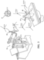
- the navigation system 20 is shown in a surgical setting such as an operating room of a medical facility.
- the navigation system 20 is set up to track movement of various objects in the operating room.
- objects include, for example, a surgical instrument 22, a femur F of a patient, and a tibia T of the patient.
- the navigation system 20 tracks these objects for purposes of displaying their relative positions and orientations to the surgeon and, in some cases, for purposes of controlling or constraining movement of the surgical instrument 22 relative to a predefined path or anatomical boundary.
- Camera unit 36 is mounted on an adjustable arm to position the optical sensors 40 with a field of view of the below discussed trackers that, ideally, is free from obstructions.
- Position and orientation signals and/or data are transmitted to the navigation computer 26 for purposes of tracking the objects.
- the computer cart assembly 24, display 28, and camera unit 36 may be like those described in U.S. Patent No. 7,725,162 to Malackowski, et al. issued on May 25, 2010 , entitled "Surgery System”.
- the navigation computer 26 can be a personal computer or laptop computer.
- Navigation computer 26 has the displays 28, 29, central processing unit (CPU) and/or other processors, memory (not shown), and storage (not shown).
- the navigation computer 26 is loaded with software as described below.
- the software converts the signals received from the camera unit 36 into data representative of the position and orientation of the objects being tracked.
- the trackers 44, 46, 48 can be battery powered with an internal battery or may have leads to receive power through the navigation computer 26, which, like the camera unit 36, preferably receives external power.
- the surgical instrument 22 may be manually positioned by only the hand of the user, without the aid of any cutting guide, jib, or other constraining mechanism such as a manipulator or robot.
- a surgical instrument is described in U.S. Patent Application No. 13/600,888, filed August 31, 2012 , entitled, "Surgical Instrument Including Housing, a Cutting Accessory that Extends from the Housing and Actuators that Establish the Position of the Cutting Accessory Relative to the Housing.”
- the optical sensors 40 of the localizer 34 receive light signals from the trackers 44, 46, 48.
- the trackers 44, 46, 48 are active trackers.
- each tracker 44, 46, 48 has at least three active tracking elements or markers 50 for transmitting light signals to the optical sensors 40.
- the active markers 50 can be, for example, light emitting diodes (LEDs) 50 transmitting light, such as infrared light.
- the optical sensors 40 preferably have sampling rates of 100 Hz or more, more preferably 300 Hz or more, and most preferably 500 Hz or more. In some embodiments, the optical sensors 40 have sampling rates of 1000 Hz.
- the sampling rate is the rate at which the optical sensors 40 receive light signals from sequentially fired LEDs 50. In some embodiments, the light signals from the LEDs 50 are fired at different rates for each tracker 44, 46, 48.
- each of the LEDs 50 are connected to a tracker controller 62 located in a housing (not shown) of the associated tracker 44, 46, 48 that transmits/receives data to/from the navigation computer 26.
- the tracker controllers 62 transmit data on the order of several Megabytes/second through wired connections with the navigation computer 26. In other embodiments, a wireless connection may be used.
- the navigation computer 26 has a transceiver (not shown) to receive the data from the tracker controller 62.
- the trackers 44, 46, 48 may have passive markers (not shown), such as reflectors that reflect light emitted from the camera unit 36. The reflected light is then received by the optical sensors 40. Active and passive marker arrangements are well known in the art.
- Each of the gyroscope sensors 60 and accelerometers 70 communicate with the tracker controller 62 located in the housing of the associated tracker that transmits/receives data to/from the navigation computer 26.
- the data can be received either through a wired or wireless connection.
- the navigation processor 52 could include one or more processors to control operation of the navigation computer 26.
- the processors can be any type of microprocessor or multi-processor system.
- the term processor is not intended to be limited to a single processor.
- navigation processor 52 Prior to the start of the surgical procedure, additional data are loaded into the navigation processor 52. Based on the position and orientation of the trackers 44, 46, 48 and the previously loaded data, navigation processor 52 determines the position of the working end of the surgical instrument 22 and the orientation of the surgical instrument 22 relative to the tissue against which the working end is to be applied. In some embodiments, navigation processor 52 forwards these data to a manipulator controller 54. The manipulator controller 54 can then use the data to control a robotic manipulator 56 as described in U.S. Patent Application No. 13/958,070, filed August 2, 2013 , entitled, "Surgical Manipulator Capable of Controlling a Surgical Instrument in Multiple Modes.”
- the navigation processor 52 also generates image signals that indicate the relative position of the surgical instrument working end to the surgical site. These image signals are applied to the displays 28, 29. Displays 28, 29, based on these signals, generate images that allow the surgeon and staff to view the relative position of the surgical instrument working end to the surgical site.
- the displays, 28, 29, as discussed above, may include a touch screen or other input/output device that allows entry of commands.
- tracking of objects is generally conducted with reference to a localizer coordinate system LCLZ.
- the localizer coordinate system has an origin and an orientation (a set of x, y, and z axes).
- pre-operative images of the femur F and tibia T are generated (or of other tissues in other embodiments). These images may be based on magnetic resonance imaging (MRI) scans, radiological scans or computed tomography (CT) scans of the patient's anatomy. These images are mapped to the femur coordinate system FBONE and tibia coordinate system TBONE using well known methods in the art.
- a pointer instrument P such as disclosed in U.S. Patent No. 7,725,162 to Malackowski, et al. having its own tracker PT (see Figure 2 ), may be used to map the femur coordinate system FBONE and tibia coordinate system TBONE to the pre-operative images. These images are fixed in the femur coordinate system FBONE and tibia coordinate system TBONE.
- the bone trackers 44, 46 are firmly affixed to the bones of the patient.
- the pose (position and orientation) of coordinate systems FBONE and TBONE are mapped to coordinate systems BTRK1 and BTRK2, respectively. Given the fixed relationship between the bones and their bone trackers 44, 46, the pose of coordinate systems FBONE and TBONE remain fixed relative to coordinate systems BTRK1 and BTRK2, respectively, throughout the procedure.
- the pose-describing data are stored in memory integral with both manipulator controller 54 and navigation processor 52.
- Localization engine 100 receives as inputs the optically-based signals from the camera controller 42 and the non-optically based signals from the tracker controller 62. Based on these signals, localization engine 100 determines the pose of the bone tracker coordinate systems BTRK1 and BTRK2 in the localizer coordinate system LCLZ. Based on the same signals received for the instrument tracker 48, the localization engine 100 determines the pose of the instrument tracker coordinate system TLTR in the localizer coordinate system LCLZ.
- Trackers 44, 46 are shown in Figures 4-6 .
- Trackers 44, 46 are configured to be attached to bone and fixed in position relative to the bone. As a result, movement of the bone results in corresponding and like movement of the trackers 44, 46.
- both trackers 44, 46 comprise the same or substantially the same components.
- the trackers 44, 46 differ in one or more components. For simplicity, only tracker 44 will be described below, but it is understood that tracker 46 may be the same or substantially the same as tracker 44.
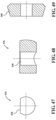
- the bone plate 200 has top and bottom surfaces 216, 218 with three side surfaces 220, 222, 224.
- the side surfaces 220, 222, 224 extend between the top and bottom surfaces 216, 218.
- the concavity of the bone plate 200 can be given by a radius of curvature R1 of the top surface 216 of from about 5 millimeters to about 50 millimeters and a radius of curvature R2 of the bottom surface 218 of from about 5 millimeters to about 50 millimeters (see Figure 9 ).
- the radius of curvature R1 is from about 15 millimeters to about 35 millimeters and the radius of curvature R2 is from about 15 millimeters to about 35 millimeters.
- Each spike 204 has a sharp tip 226 (see Figure 10 ) that is formed near the intersection of the bottom surface 218 and two adjacent side surfaces 220, 222, 224.
- the bottom surface 218 extends arcuately along each spike 204 to the sharp tip 226 to form a gradual taper to the sharp tip 226.
- the bottom surface 218 is generally concavely shaped between sharp tips 226.
- tissue such as muscle, ligaments, and the like may be present on top of the bone to which the bone plate 200 is to be secured. This tissue can be accommodated in this space without affecting the engagement of the sharp tips 226 in the bone.
- Three openings 228 are defined through the bone plate 200 to receive the bone screws 202. These three openings 228 have the cross-sectional configuration shown in Figure 10 .
- One embodiment of this configuration is shown in U.S. Patent No. 6,322,562 to Wolter in order to receive threaded heads 205 of the bone screws 202 shown in Figures 11-15 .
- Each of the openings 228 are defined about an axis A.
- Each opening 228 comprises a generally cylindrical throughbore 230 defined by inner surface 234.
- the throughbore 230 is centered about the axis A.
- An integral flange 232 is located in the throughbore 230 and directed radially inward toward axis A.
- the flange 232 is spaced from the top and bottom surfaces 216, 218 of the bone plate 200.
- This flange 232 is disposed annularly about axis A and generally perpendicular to axis A.
- the flange 232 tapers in cross-section from the inner surface 234 to an end surface 236.
- the end surface 236 defines an opening (not numbered) that is cylindrical in shape.
- the taper of the flange 232 is symmetrically formed by upper and lower surfaces 240, 242.
- the upper surface 240 extends at an acute angle ⁇ from end surface 236 to inner surface 234.
- the lower surface 242 extends at the same acute angle ⁇ from the end surface 236 to the inner surface 234, but in the opposite direction.
- a recess 244 is defined in the top surface 216 of the bone plate 200.
- the recess 244 is generally rectangular in shape for mating reception of the base plate 208 of the extension arm 206.
- the base plate 208 is sized so that once located in the recess 244 the extension arm 206 is substantially prevented from rotation relative to the bone plate 200.
- a central opening 246 is located in the recess 244 and is defined through the bone plate 200.
- the central opening 246 receives a bone screw 202 similar to the openings 228, but has a different cross-section than openings 228.
- the central opening 246 is a generally cylindrical throughbore of single diameter that is substantially perpendicular to the bone plate 200 at that location.
- An axis C defines a center of the throughbore 246, as shown in Figure 9 .
- the openings 228 are spaced equidistantly from the axis C. Additionally, the openings 228 are spaced equally circumferentially about an imaginary circle defined through axes A of each of the openings 228 (see Figure 8 ).
- a normal directional vector V to the bone plate 200 is defined downwardly along axis C toward the patient's anatomy when mounted.
- Inclined directional vectors I arranged at acute angle ⁇ to the normal directional vector V, are defined downwardly along axes A.
- these inclined directional vectors I are generally directed toward the normal directional vector V and cross the normal directional vector V at the same point INT along axis C. This orientation assists with preventing pull-out of the bone screws 202 from forces acting on the bone plate 200.
- the bone plate 200 may be formed of stainless steel, cobalt base alloys, bioceramics, titanium alloys, titanium, or other biocompatible materials.
- Bone screws 202 are shown in Figures 11-15 .
- the bone screws are similar to those shown in U.S. Patent No. 6,322,562 .
- Each of the bone screws 202 has self tapping threads 203 for engaging bone.
- the bone screws 202 also have the threaded heads 205 for engaging the flanges 232 of the openings 228.
- the bone screws 202 may be of different sizes depending on the tissue to which they are being mounted. For instance, if the bone plate 200 is configured for mounting to a patella, smaller bone screws may be utilized. If the bone plate 200 is being mounted to the tibia, which is typically harder than other bones of the body, smaller bone screws may be used. For soft bone, longer bone screws that implant deeper into the bone may be desired.
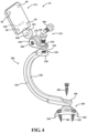
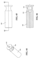
- a mounting surface 258 is located at the mounting end 210 of the extension arm 206.
- the mounting surface 258 is configured to support the connector assembly 214 and tracking head 212.
- the mounting surface 258 is generally planar.
- a threaded opening 260 is defined through the mounting end 210 for receiving a threaded adjustment fastener 261 (see Figure 4 ).
- the extension arm 206 is generally C-shaped to define a tissue receiving area 262 between the tracker head 212 and the bone plate 200.
- the tissue receiving area 262 is configured to receive soft tissue such as skin, fat, muscle, etc. above the bone plate 200 when the bone plate 200 is mounted to the bone.
- the tissue receiving area 262 enables the user to retract soft tissue away from bone, mount the bone plate 200 directly to the bone, and then release the soft tissue back to a position above the bone plate 200. Accordingly, the soft tissue is not required to be continually retracted during the entire surgical procedure.
- Figure 21 shows layers of skin, fat, muscle, and fascia being located in the tissue receiving area 262 while the bone plate 200 is mounted to the femur F. In particular, the sharp tips 226 penetrate through the periosteum into the hard cortical bone of the femur F.
- the tracking head 212 includes the plurality of LEDs 50, gyroscope sensor 60 (not shown), accelerometer 70 (not shown), and a transceiver (not shown) for receiving and transmitting signals to and from the camera unit 36 and/or navigation computer 26.
- the tracking head 212 may also be connected to the navigation computer 26 via a wired connection as previously described.
- the connector assembly 214 is shown in Figures 4 and 23-26 .
- the connector assembly 214 includes a connector 270 for interconnecting the tracking head 212 and the extension arm 206.
- the connector 270 includes a pair of second hinge members 278.
- a space 280 is defined between the second hinge members 278 for receiving the first hinge member 264.
- One of the second hinge members 278 has a non-threaded bore 282, while the other has a threaded bore 284.
- a threaded adjustment fastener 286 passes through the non-threaded bore 282 into the threaded bore 284.
- Rotational base 290 When tightening the adjustment fastener 261 the rotational base 290 is drawn against the mounting surface 258. Friction between the bottom of the rotational base 290 and the mounting surface 258 prevents rotational movement of the connector 270 relative to the mounting surface 258. When the adjustment fastener 261 is loosened, the connector 270 can be rotated freely relative to the mounting surface 258. Thus, the tracking head 212 can be rotated relative to the bone plate 200. Rotation occurs in one degree of freedom about rotational axis R (see Figures 5 and 6 ). Rotational axis R is defined centrally through bore 294 and threaded opening 260.
- the navigation computer 26 determines that there is an error if any one of the optical sensors 40 fails to receive a signal from an LED 50, even though other sensors 40 still receive the signal. In other embodiments, navigation computer 26 determines that there is an error if none of the optical sensors 40 receive the signal. In either case, when the navigation system 20 determines that there is an error based on the failure of one or more sensors 40 to receive signals from one or more LEDs 50, an error signal is generated by the navigation computer 26. An error message then appears on displays 28, 29. The navigation computer 26 also transmits an error signal to the tracker controller 62.
- the indicating LEDs 302 may include separate indicating LEDs that are alternately activated based on the error status - one or more first colored indicating LEDs for error and one or more second colored indicating LEDs for no error.
- the indicator 300 may include an LED or LCD display with error message and/or audible alerts when there is an error.
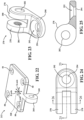
- tracking head 412 supports first indicator LEDs 402 that emit orange colored light and second indicator LEDs 404 that emit green colored light.
- the tracking head 412 includes a top 414 supporting the LEDs 50.
- Sapphire domes 418 cover the LEDs 50.
- the tracking head 412 further includes a bottom 420.
- Figure 31 shows an electrical schematic of the tracker controller 62 and the indicator LEDs 402, 404.
- the electrical schematic shows the electrical components that facilitate alternating activation/deactivation of the indicator LEDs 402, 404.
- Each of the indicator LEDs 402, 404 includes an anode 432 and a cathode 434.
- the anode 432 of each of the indicator LEDs 402, 404 connects to a first voltage reference 436 and the cathode 434 of each of the indicator LEDs 402, 404 connects to a second voltage reference 438.
- the first voltage reference 436 is +5 VDC and the second voltage reference 438 is signal ground.
- the anode 432 of each of the indicator LEDs 402, 404 may connect to the first voltage reference 438 separately, or in combination, as shown in Figure 31 .
- the first and second indicator control signals may correspond to any suitable predetermined voltage or current for controlling MOSFETs M1, M2.
- each of the LEDs 50 includes an anode 450 and a cathode 452.
- the anode 450 of each of the LEDs 50 connects to a third voltage reference 454 while the cathode 452 of each of the LEDs 50 connects to a fourth voltage reference 456.
- the third voltage reference 454 is +2 VDC and the fourth voltage reference 456 is signal ground.
- the anode 450 of each of the LEDs 50 may connect to the third voltage reference 454 separately, or in combination, as shown in Figure 32 .
- the tracker controller 62 controls activation/deactivation of the LEDs 50. Mainly, the tracker controller 62 selectively controls the switching elements M3, M4, M5, M6 to allow or prevent current flow through the LEDs 50.
- the voltage sensing circuit 470 sends to the tracker controller 62 a voltage sense signal representing a measured operating voltage of the LEDs 50.
- the voltage sensing circuit 470 protects the LEDs 50 from inappropriate voltage conditions.
- the tracker controller 62 may process the voltage sense signal and, in response, modify the LED control signal based on the value of the voltage sense signal. For instance, the tracker controller 62 may change the voltage of the LED control signal(s) if the tracker controller 62 determines that the voltage sense signal is above a predetermined threshold level.
- the tracker controller 62 utilizes the voltage sensing circuit 470 for determining whether an LED 50 is malfunctioning.
- the tracker controller 62 can communicate the malfunction of the LED 50 to the navigation system 20 so that the navigation system 20 can anticipate such malfunction and respond accordingly.
- the voltage sensing circuit 470 may be implemented according to various other configurations and methods.
- the first input terminal 486 of the amplifier 482 connects to the tracker controller 62.
- the second input terminal 488 of the amplifier 482 connects to the gate and the source of the MOSFET M7.
- a capacitor C3 is included between the second input terminal 488 and the gate of the MOSFET M7.
- a resistor R5 is included between the second input terminal 488 and the source of the MOSFET M7.
- Resistor R6 connects between the source of the MOSFET M7 and the signal ground 456.
- the output terminal 490 of the amplifier 482 connects to the gate of the MOSFET M7.
- Resistor R7 connects between the output 490 of the amplifier 484 and the gate of the MOSFET M7.
- the drain of the MOSFET M7 connects to the sources of the MOSFETs M3, M4, M5, M6 at the shared line 458.
- the tracker controller 62 sends a current limiting signal to the current limiting circuit 482.
- the tracker controller 62 may send the current limiting signal based on the value of the current sense signal provided by the current sensing circuit 480.
- the current limiting signal sent by the tracker controller 62 is received at the first input terminal 486 of the amplifier 482.
- the amplifier 484 controls the MOSFET M7 based on the current limiting signal received from the tracker controller 62.
- the amplifier 484 deactivates each of the LEDs 50 in response to the current limiting signal.
- the amplifier 484 delivers a signal from the output terminal 490 to the gate of MOSFET M7.
- the tracking head 212 is movable relative to the bone plate 200 via the connector assembly 214.
- the tracking head 212 is movable about pivot axis P and rotational axis R (see Figure 4 ).
- the connector assembly 214 allows movement of the tracking head 212 in these two degrees of freedom relative to the bone plate 200 to place the tracking head 212 in the desired orientation. This helps to provide the line-of-sight between the LEDs 50 and the optical sensors 40.
- the signals transmitted by the LEDs 50 are considered line-of-sight tracking signals that have a central signal axis 322 defining the center of a signal emitting region 324.
- the desired orientation is further defined in one embodiment as the central signal axes 322 of the LEDs 50 being perpendicular to the direction of gravity, e.g., perpendicular to a vector 326 oriented in the direction of gravity.
- an LED on the tracking head 212 may indicate to the user when the current orientation is at the desired orientation by being activated to emit a green colored light.
- an audible indicator may be provided on the tracker 44 to indicate that the tracking head 212 is in the desired orientation.
- the LEDs 50 are being tracked by the optical sensors 40.
- the navigation computer 26 is configured to determine, based on the signals received by the optical sensors 40, which rotational orientation of the tracking head 212 provides the best line-of-sight to the LEDs 50.
- an LED on the tracking head 212 may indicate to the user when the rotational position is at the desired rotational position by being activated to emit a green colored light.
- an audible indicator may be provided on the tracker 44 to indicate that the current rotational position is at the desired rotational position.
- the desired rotational position may include predefined deviations from an ideal rotational position, such as deviations of +/- ten percent, +/- five percent, or +/- two percent.
- the desired orientation can be determined by instructing the user to tilt and rotate the tracking head 212 through their maximum ranges of movement, one or more times, either sequentially or alternately. While the tracking head 212 is tilted and rotated, the navigation computer 26 determines at which tilt and rotational positions (e.g., tilt and rotational angles) about axes P and R line of sight for each LED 50 is present and at which tilt and rotational positions there is no line of sight for each LED 50. This will determine a range of line-of-sight positions about axes P and R for each LED 50. A best fit algorithm can then be used to determine the positions about axes P and R that best fits within the ranges of line-of-sight positions for all of the LEDs 50.
- tilt and rotational positions e.g., tilt and rotational angles
- This process may be iterative and include several adjustments by the user about the axes P and R to find a suitable position for the tracking head 212.
- the navigation computer 26 may be unable to identify an orientation in which line-of-sight is maintained for all of the LEDs 50 because of a poor initial orientation set by the user.
- the navigation computer 26 may first instruct the user to reorient the tracking head 212 so that the LEDs 50 visually appear to be facing the optical sensors 40 and then continue with measuring the orientation of the tracking head 212 through various movements to find the best fit that maintains the line-of-sight for all of the LEDs 50.
- tilting adjustment may be processed first with the tracking head 212 being moved through its entire range of tilting motion, one or more times, and possibly at multiple knee positions including flexed and extended positions.
- the best fit tilt angle is then determined and the tilt angle is then fixed at the best fit tilt angle.
- the tracking head 212 can thereafter be moved through its entire range of rotational motion, one or more times, and possibly at multiple knee positions including flexed and extended positions.
- the best fit rotational angle is then determined and the rotational angle is then fixed at the best fit rotational angle.
- a third degree of freedom may be adjusted to a desired position, such as a height of the tracker 44.
- a desired position such as a height of the tracker 44.
- the LEDs 50 of the tracking head 212 may be raised or lowered relative to the optical sensors 40 without breaking the line-of-sight between the LEDs 50 and sensors 40.
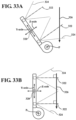
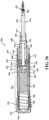
- a screw driver 500 is shown in Figures 35-51 .
- the screw driver 500 is used to place the bone screws 202.
- the screw driver 500 includes an integrated impactor 502 that punches each bone screw 202 into the bone prior to screwing.
- the impactor 502 stores energy in a rear spring 504. The energy is eventually released as a force that drives the bone screw 202 into the bone.
- the impactor 502 starts in a rest state in which no energy is stored, is operated to gradually increase the stored energy, and then is actuated to release the energy.
- the screw driver 500 includes a body.
- the body comprises a nose tube 508, middle tube 510, and rear cap 512.
- the nose tube 508, middle tube 510, and rear cap 512 are separate parts that are releasably connected together for purposes of assembling internal components. It should be appreciated that in other embodiments, the nose tube 508, middle tube 510, and rear cap 512 may be permanently fixed together.
- the nose tube 508 has a generally conical distal end 514.
- the nose tube 508 extends from its distal end 514 to an externally threaded proximal end 516.
- the nose tube 508 is hollow.
- the nose tube 508 defines a proximal bore 518 and distal bore 520.
- the proximal bore 518 is larger in cross-sectional area than the distal bore 520.
- the proximal bore 518 is circular in cross-section and the distal bore 520 is hexagonal in cross-section.
- the middle tube 510 is generally cylindrical.
- the middle tube 510 has an internally threaded distal end 522 and an externally threaded proximal end 524.
- the internally threaded distal end 522 threads onto the externally threaded proximal end 516 of the nose tube 508.
- the rear cap 512 has a top 526.
- the rear cap 512 extends distally from the top 526 to an internally threaded section 528.
- the internally threaded section 528 threads onto the externally threaded proximal end 524 of the middle tube 510.
- the impactor 502 includes a hammer 530 disposed in the middle tube 510.
- the hammer 530 is generally cylindrical in shape.
- the rear spring 504 is disposed between the rear cap 512 and the hammer 530. The rear spring 504 biases the hammer 530 distally. Compression of the rear spring 504 can be adjusted by loosening or tightening the rear cap 512 to decrease or increase the stored energy of the hammer 530.
- a receiving hole 532 is formed in the hammer 530.
- the receiving hole 532 is disposed about a central axis of the hammer 530.
- the receiving hole 532 is cylindrically shaped.
- a cross bore 534 is formed in a direction perpendicular to the receiving hole 532 (see Figure 46 ).
- the impactor 502 includes a trigger 536 located in the cross bore 534.
- the trigger 536 is semi-cylindrical in shape.
- the trigger 536 has a flat bottom 538 (see Figure 47 ).
- a throughbore 540 is defined in the trigger 536.
- a driving rod 544 ultimately receives the energy stored in the impactor 502 to drive in the bone screws 202.
- the driving rod 544 has a cylindrical shaft 546 with a proximal end 548.
- the proximal end 548 is shaped for mating reception within the receiving hole 532 of the hammer 530.
- a boss 550 is located on the proximal end 548 of the driving rod 544 to form a shoulder 552 (see Figure 50 ).
- the shoulder 552 engages the flat bottom 538 of the trigger 536.
- the boss 550 protrudes into the throughbore 540 defined in the trigger 536, but the shoulder 552 prevents the cylindrical shaft 546 from entering the throughbore 540.
- the driving rod 544 has a hexagonal shaft 554 with a distal end 556.
- the hexagonal shaft 554 mates with the hexagonal-shaped distal bore 520 of the nose tube 508 so that rotation of the body by the user also rotates the hexagonal shaft 554.
- the distal end 556 has features adapted to engage heads of the bone screws 202 to rotate and drive the bone screws 202 into the bone when the body of the screw driver 500 is rotated.
- a collar 558 is fixed to the hexagonal shaft 554.
- the collar 558 prevents the driving rod 544 from falling out of the nose tube 508.
- the collar 558 is cylindrical in shape to mate with the proximal bore 518 of the nose tube 508.
- a spring cap 560 is centrally disposed inside the middle tube 510 between the nose tube 508 and the hammer 530.
- the spring cap 560 is press fit inside the middle tube 510.
- a rod spring 562 is disposed about the cylindrical shaft 546 of the driving rod 544.
- the rod spring 562 acts between the spring cap 560 and the collar 558 of the driving rod 544 to return the screw driver 500 to the rest state after the hammer 530 is actuated.
- the spring cap 560 defines a throughbore (not numbered) for receiving the cylindrical shaft 546 of the driving rod 544 and centering the cylindrical shaft 546 inside the middle tube 510.
- the screw driver 500 is pressed against the bone screw 202 by gripping the rear cap 512 and/or middle tube 510 and urging them distally.
- the bone screw 202 is thus pressed against the bone.
- the driving rod 544 travels proximally in the middle tube 510.
- the shoulder 552 pushes the trigger 536 proximally while the leaf spring 542 keeps the trigger 536 throughbore 540 misaligned with the receiving hole 532 of the hammer 530.
- the middle tube 510 includes an inclined inner surface 566.
- the inclined inner surface 566 engages the trigger 536 when the trigger 536 reaches the inclined inner surface 566.
- the inclined inner surface 566 acts like a cam to push the trigger 536 in a manner that centers the throughbore 540 of the trigger 536 and places the throughbore 540 into alignment with the receiving hole 532 of the hammer 530.
- the proximal end 548 of the driving rod 544 is now aligned to fit within the throughbore 540, which allows the trigger 536 to slide down the driving rod 544 thereby releasing the hammer 530.
- the hammer 530 then moves forward, propelled by the rear spring 504.
- the boss 550 on the proximal end 548 of the driving rod 544 eventually bottoms out in the receiving hole 532 and the force of the hammer 530 is transmitted into the driving rod 544 and the bone screw 202 punching the bone screw 202 into the bone.
- the firing of the LEDs occurs such that one LED 50 from tracker 44 is fired, then one LED 50 from tracker 46, then one LED 50 from tracker 48, then a second LED 50 from tracker 44, then a second LED 50 from tracker 46, and so on until all LEDs 50 have been fired and then the sequence repeats.
- This order of firing may occur through instruction signals sent from the transceivers (not shown) on the camera unit 36 to transceivers (not shown) on the trackers 44, 46, 48 or through wired connections from the navigation computer 26 to the tracker controller 62 on each of the trackers 44, 46, 48.
- the navigation system 20 can be used in a closed loop manner to control surgical procedures carried out by surgical cutting instruments. Both the instrument 22 and the anatomy being cut are outfitted with trackers 50 such that the navigation system 20 can track the position and orientation of the instrument 22 and the anatomy being cut, such as bone.
- the navigation system 20 is part of a robotic surgical system for treating tissue.
- the robotic surgical system is a robotic surgical cutting system for cutting away material from a patient's anatomy, such as bone or soft tissue.
- the cutting system could be used to prepare bone for surgical implants such as hip and knee implants, including unicompartmental, bicompartmental, or total knee implants.
- the navigation system 20 communicates with a robotic control system (which can include the manipulator controller 54).
- the navigation system 20 communicates position and/or orientation data to the robotic control system.
- the position and/or orientation data is indicative of a position and/or orientation of instrument 22 relative to the anatomy. This communication provides closed loop control to control cutting of the anatomy such that the cutting occurs within a predefined boundary.
- each of the femur F and tibia T has a target volume of material that is to be removed by the working end of the surgical instrument 22.
- the target volumes are defined by one or more boundaries.
- the boundaries define the surfaces of the bone that should remain after the procedure.
- navigation system 20 tracks and controls the surgical instrument 22 to ensure that the working end, e.g., bur, only removes the target volume of material and does not extend beyond the boundary, as disclosed in U.S. Patent Application No. 13/958,070, filed August 2, 2013 , entitled, "Surgical Manipulator Capable of Controlling a Surgical Instrument in Multiple Modes".
Landscapes
- Health & Medical Sciences (AREA)
- Surgery (AREA)
- Life Sciences & Earth Sciences (AREA)
- Engineering & Computer Science (AREA)
- Animal Behavior & Ethology (AREA)
- Veterinary Medicine (AREA)
- Biomedical Technology (AREA)
- Heart & Thoracic Surgery (AREA)
- Medical Informatics (AREA)
- Molecular Biology (AREA)
- Nuclear Medicine, Radiotherapy & Molecular Imaging (AREA)
- General Health & Medical Sciences (AREA)
- Public Health (AREA)
- Robotics (AREA)
- Orthopedic Medicine & Surgery (AREA)
- Oral & Maxillofacial Surgery (AREA)
- Pathology (AREA)
- Surgical Instruments (AREA)
- Optical Radar Systems And Details Thereof (AREA)
- Pharmaceuticals Containing Other Organic And Inorganic Compounds (AREA)
- User Interface Of Digital Computer (AREA)
Priority Applications (1)
| Application Number | Priority Date | Filing Date | Title |
|---|---|---|---|
| EP23215411.2A EP4309613A3 (en) | 2013-01-16 | 2014-01-16 | Navigation systems for indicating line-of-sight errors |
Applications Claiming Priority (3)
| Application Number | Priority Date | Filing Date | Title |
|---|---|---|---|
| US201361753219P | 2013-01-16 | 2013-01-16 | |
| PCT/US2014/011821 WO2014113551A2 (en) | 2013-01-16 | 2014-01-16 | Navigation systems and methods for indicating and reducing line-of-sight errors |
| EP14703671.9A EP2945559B1 (en) | 2013-01-16 | 2014-01-16 | Navigation systems and methods for indicating and reducing line-of-sight errors |
Related Parent Applications (2)
| Application Number | Title | Priority Date | Filing Date |
|---|---|---|---|
| EP14703671.9A Division EP2945559B1 (en) | 2013-01-16 | 2014-01-16 | Navigation systems and methods for indicating and reducing line-of-sight errors |
| EP14703671.9A Division-Into EP2945559B1 (en) | 2013-01-16 | 2014-01-16 | Navigation systems and methods for indicating and reducing line-of-sight errors |
Related Child Applications (1)
| Application Number | Title | Priority Date | Filing Date |
|---|---|---|---|
| EP23215411.2A Division EP4309613A3 (en) | 2013-01-16 | 2014-01-16 | Navigation systems for indicating line-of-sight errors |
Publications (2)
| Publication Number | Publication Date |
|---|---|
| EP3424459A1 EP3424459A1 (en) | 2019-01-09 |
| EP3424459B1 true EP3424459B1 (en) | 2023-12-13 |
Family
ID=50071738
Family Applications (3)
| Application Number | Title | Priority Date | Filing Date |
|---|---|---|---|
| EP14703671.9A Active EP2945559B1 (en) | 2013-01-16 | 2014-01-16 | Navigation systems and methods for indicating and reducing line-of-sight errors |
| EP23215411.2A Pending EP4309613A3 (en) | 2013-01-16 | 2014-01-16 | Navigation systems for indicating line-of-sight errors |
| EP18186800.1A Active EP3424459B1 (en) | 2013-01-16 | 2014-01-16 | Navigation systems for indicating line-of-sight errors |
Family Applications Before (2)
| Application Number | Title | Priority Date | Filing Date |
|---|---|---|---|
| EP14703671.9A Active EP2945559B1 (en) | 2013-01-16 | 2014-01-16 | Navigation systems and methods for indicating and reducing line-of-sight errors |
| EP23215411.2A Pending EP4309613A3 (en) | 2013-01-16 | 2014-01-16 | Navigation systems for indicating line-of-sight errors |
Country Status (8)
| Country | Link |
|---|---|
| US (4) | US9566120B2 (zh) |
| EP (3) | EP2945559B1 (zh) |
| JP (2) | JP6472757B2 (zh) |
| CN (2) | CN108742842B (zh) |
| AU (2) | AU2014207502B2 (zh) |
| CA (1) | CA2895134A1 (zh) |
| CR (1) | CR20150376A (zh) |
| WO (1) | WO2014113551A2 (zh) |
Families Citing this family (70)
| Publication number | Priority date | Publication date | Assignee | Title |
|---|---|---|---|---|
| JP6385275B2 (ja) | 2011-09-02 | 2018-09-05 | ストライカー・コーポレイション | ハウジングから延びる切断アクセサリ及びハウジングに対する切断アクセサリの位置を確立するアクチュエータを備える手術器具 |
| US11896446B2 (en) * | 2012-06-21 | 2024-02-13 | Globus Medical, Inc | Surgical robotic automation with tracking markers |
| US11786324B2 (en) * | 2012-06-21 | 2023-10-17 | Globus Medical, Inc. | Surgical robotic automation with tracking markers |
| US9993273B2 (en) | 2013-01-16 | 2018-06-12 | Mako Surgical Corp. | Bone plate and tracking device using a bone plate for attaching to a patient's anatomy |
| JP6472757B2 (ja) | 2013-01-16 | 2019-02-20 | ストライカー・コーポレイション | 見通し線エラーを示し、かつ低減させるためのナビゲーションシステムおよび方法 |
| WO2014144321A1 (en) | 2013-03-15 | 2014-09-18 | Stryker Corporation | Assembly for positioning a sterile surgical drape relative to optical position sensors |
| DE102013222230A1 (de) | 2013-10-31 | 2015-04-30 | Fiagon Gmbh | Chirurgisches Instrument |
| WO2016044830A1 (en) * | 2014-09-19 | 2016-03-24 | Think Surgical, Inc. | System and process for ultrasonic determination of long bone orientation |
| US9844360B2 (en) * | 2014-10-27 | 2017-12-19 | Clear Guide Medical, Inc. | System and devices for image targeting |
| CN107106228B (zh) | 2014-10-31 | 2020-05-05 | 美敦力先进能量有限公司 | 用于减少rf发生器中的泄漏电流的功率监测电路与方法 |
| CN107205786B (zh) * | 2015-02-25 | 2020-08-25 | 马科外科公司 | 用于在外科手术过程中减少跟踪中断的导航系统和方法 |
| EP3313309B1 (en) | 2015-06-23 | 2021-07-21 | Stryker Corporation | Delivery system for delivering material to a target site |
| US10117713B2 (en) | 2015-07-01 | 2018-11-06 | Mako Surgical Corp. | Robotic systems and methods for controlling a tool removing material from a workpiece |
| US11197682B2 (en) * | 2015-08-27 | 2021-12-14 | Globus Medical, Inc. | Proximal humeral stabilization system |
| US10034716B2 (en) * | 2015-09-14 | 2018-07-31 | Globus Medical, Inc. | Surgical robotic systems and methods thereof |
| US20170086941A1 (en) * | 2015-09-25 | 2017-03-30 | Atracsys | Marker for Optical Tracking System |
| KR20180071328A (ko) * | 2015-11-16 | 2018-06-27 | 씽크 써지컬, 인크. | 추적된 뼈의 정합을 확인하기 위한 방법 |
| JP2019500940A (ja) * | 2015-12-10 | 2019-01-17 | ストライカー・コーポレイション | ナビゲーションシステムに用いられる追跡装置及び該追跡装置を製造するための方法 |
| EP3804644B1 (en) * | 2015-12-15 | 2022-09-14 | TechMah Medical LLC | Femoral base plate for total hip arthroplasty |
| KR20180099702A (ko) | 2015-12-31 | 2018-09-05 | 스트리커 코포레이션 | 가상 객체에 의해 정의된 타깃 부위에서 환자에게 수술을 수행하기 위한 시스템 및 방법 |
| US20170311843A1 (en) * | 2016-04-27 | 2017-11-02 | Brent Andrew BAILEY | Medical instrument tracking indicator system |
| WO2017205351A1 (en) | 2016-05-23 | 2017-11-30 | Mako Surgical Corp. | Systems and methods for identifying and tracking physical objects during a robotic surgical procedure |
| US10537395B2 (en) | 2016-05-26 | 2020-01-21 | MAKO Surgical Group | Navigation tracker with kinematic connector assembly |
| CN106236262A (zh) * | 2016-08-08 | 2016-12-21 | 张海燕 | 光学跟踪定位神经导航装置 |
| US10004609B2 (en) | 2016-09-23 | 2018-06-26 | Warsaw Orthopedic, Inc. | Surgical instrument and method |
| EP3375399B1 (en) | 2016-10-05 | 2022-05-25 | NuVasive, Inc. | Surgical navigation system |
| DE102017102256A1 (de) * | 2016-11-14 | 2018-05-17 | Osram Oled Gmbh | Vorrichtung, referenzobjekt für eine vorrichtung und verfahren zum betreiben einer vorrichtung zum ermitteln einer vorgegebenen information eines objektes entlang einer transportstrecke |
| US10499997B2 (en) | 2017-01-03 | 2019-12-10 | Mako Surgical Corp. | Systems and methods for surgical navigation |
| US10806529B2 (en) * | 2017-07-20 | 2020-10-20 | Mako Surgical Corp. | System and method for robotically assisting a surgical procedure |
| US10675094B2 (en) * | 2017-07-21 | 2020-06-09 | Globus Medical Inc. | Robot surgical platform |
| CN107582167A (zh) * | 2017-09-19 | 2018-01-16 | 上海龙慧医疗科技有限公司 | 骨科关节置换手术系统 |
| CN109674533B (zh) * | 2017-10-18 | 2022-07-05 | 刘洋 | 基于便携式彩超设备的手术导航系统及方法 |
| US11173048B2 (en) | 2017-11-07 | 2021-11-16 | Howmedica Osteonics Corp. | Robotic system for shoulder arthroplasty using stemless implant components |
| US11432945B2 (en) | 2017-11-07 | 2022-09-06 | Howmedica Osteonics Corp. | Robotic system for shoulder arthroplasty using stemless implant components |
| US11241285B2 (en) | 2017-11-07 | 2022-02-08 | Mako Surgical Corp. | Robotic system for shoulder arthroplasty using stemless implant components |
| US11272985B2 (en) | 2017-11-14 | 2022-03-15 | Stryker Corporation | Patient-specific preoperative planning simulation techniques |
| US10555781B2 (en) * | 2017-11-15 | 2020-02-11 | Stryker Corporation | High bandwidth and low latency hybrid communication techniques for a navigation system |
| US11351007B1 (en) | 2018-01-22 | 2022-06-07 | CAIRA Surgical | Surgical systems with intra-operative 3D scanners and surgical methods using the same |
| US11114199B2 (en) | 2018-01-25 | 2021-09-07 | Mako Surgical Corp. | Workflow systems and methods for enhancing collaboration between participants in a surgical procedure |
| EP3537410A1 (en) * | 2018-03-07 | 2019-09-11 | Seabery North America, S.L. | Systems and methods to simulate joining operations on customized workpieces |
| US11191594B2 (en) * | 2018-05-25 | 2021-12-07 | Mako Surgical Corp. | Versatile tracking arrays for a navigation system and methods of recovering registration using the same |
| US11007018B2 (en) | 2018-06-15 | 2021-05-18 | Mako Surgical Corp. | Systems and methods for tracking objects |
| US11291507B2 (en) | 2018-07-16 | 2022-04-05 | Mako Surgical Corp. | System and method for image based registration and calibration |
| CN109044531B (zh) * | 2018-08-20 | 2024-02-06 | 真健康(北京)医疗科技有限公司 | 一种接触感应式的末端位置导航跟踪装置 |
| CN112955094B (zh) * | 2018-09-09 | 2024-04-16 | 钛隼生物科技股份有限公司 | 植牙系统及其导航方法 |
| US11684489B2 (en) | 2018-10-29 | 2023-06-27 | Mako Surgical Corp. | Robotic system for ankle arthroplasty |
| WO2020180917A1 (en) * | 2019-03-04 | 2020-09-10 | Smith & Nephew, Inc. | Co-registration for augmented reality and surgical navigation |
| US10858023B2 (en) | 2019-03-15 | 2020-12-08 | Medline Industries, Inc. | Mattress air supply device cart and methods of use |
| USD914217S1 (en) | 2019-03-15 | 2021-03-23 | Medline Industries, Inc. | Cart |
| EP3719749A1 (en) | 2019-04-03 | 2020-10-07 | Fiagon AG Medical Technologies | Registration method and setup |
| EP3975910A4 (en) * | 2019-05-30 | 2023-11-01 | Icahn School of Medicine at Mount Sinai | ROBOT-MOUNTED CAMERA TRACKING AND RECORDING SYSTEM FOR ORTHOPEDIC AND NEUROLOGICAL SURGERY |
| EP3989859A1 (en) | 2019-06-28 | 2022-05-04 | Mako Surgical Corporation | Tracker-based surgical navigation |
| AU2020300612A1 (en) | 2019-07-03 | 2022-02-03 | Stryker Corporation | Obstacle avoidance techniques for surgical navigation |
| US11612440B2 (en) | 2019-09-05 | 2023-03-28 | Nuvasive, Inc. | Surgical instrument tracking devices and related methods |
| WO2021048439A1 (en) * | 2019-09-13 | 2021-03-18 | Fiagon Ag Medical Technologies | Navigation unit and method |
| US11432882B2 (en) | 2019-09-17 | 2022-09-06 | CAIRA Surgical | System and method for medical object tracking |
| GB2589376B (en) * | 2019-11-29 | 2023-11-08 | Cmr Surgical Ltd | Detecting a trigger in a surgical robotic system |
| US11871998B2 (en) | 2019-12-06 | 2024-01-16 | Stryker European Operations Limited | Gravity based patient image orientation detection |
| US11660148B2 (en) | 2020-01-13 | 2023-05-30 | Stryker Corporation | System and method for monitoring offset during navigation-assisted surgery |
| EP4196035A1 (en) * | 2020-08-12 | 2023-06-21 | Brainlab AG | Determining an avoidance region for a reference device |
| US11571788B2 (en) | 2020-11-11 | 2023-02-07 | International Business Machines Corporation | Adjustable suction screwdriver |
| US11385614B2 (en) | 2020-11-11 | 2022-07-12 | International Business Machines Corporation | Guided driver device |
| CN112932664A (zh) * | 2021-01-27 | 2021-06-11 | 南京逸动智能科技有限责任公司 | 一种用于手术导航系统的圆形贴片 |
| CN117279563A (zh) | 2021-03-12 | 2023-12-22 | 史赛克欧洲运营有限公司 | 用于检测和去除肿瘤组织的神经外科方法和系统 |
| WO2022238982A1 (en) | 2021-05-14 | 2022-11-17 | Stryker European Operations Limited | Surgical fluorescence probe for tumor detection |
| WO2022246216A1 (en) | 2021-05-20 | 2022-11-24 | Mako Surgical Corp. | Optimization of tracker-based surgical navigation |
| US11819208B2 (en) * | 2021-08-05 | 2023-11-21 | Covidien Lp | Handheld electromechanical surgical device with strain gauge drift detection |
| US20230364746A1 (en) | 2022-05-13 | 2023-11-16 | Joseph M. Grubb | Multitool with locking multipurpose driver |
| WO2024057284A2 (en) | 2022-09-15 | 2024-03-21 | Stryker European Operations Limited | Neurosurgical methods and systems for detecting and removing tumorous tissue |
| WO2024081388A1 (en) | 2022-10-13 | 2024-04-18 | Howmedica Osteonics Corp. | System and method for implantable sensor registration |
Citations (1)
| Publication number | Priority date | Publication date | Assignee | Title |
|---|---|---|---|---|
| US20040068263A1 (en) * | 2002-10-04 | 2004-04-08 | Benoit Chouinard | CAS bone reference with articulated support |
Family Cites Families (254)
| Publication number | Priority date | Publication date | Assignee | Title |
|---|---|---|---|---|
| US3741205A (en) | 1971-06-14 | 1973-06-26 | K Markolf | Bone fixation plate |
| FR2435243B1 (fr) | 1978-09-07 | 1985-06-28 | Tornier Sa | Perfectionnements aux plaques pour osteosynthese |
| FI58669C (fi) | 1980-01-28 | 1981-03-10 | Lohja Ab Oy | Skarv foer betongpaolar |
| FR2651992B1 (fr) | 1989-09-18 | 1991-12-13 | Sofamor | Implant pour osteosynthese rachidienne dorso-lombaire anterieure destine a la correction de cyphoses. |
| ES2085885T3 (es) | 1989-11-08 | 1996-06-16 | George S Allen | Brazo mecanico para sistema interactivo de cirugia dirigido por imagenes. |
| US5108397A (en) | 1990-04-19 | 1992-04-28 | Joseph White | Method and apparatus for stabilization of pelvic fractures |
| US5017139A (en) | 1990-07-05 | 1991-05-21 | Mushabac David R | Mechanical support for hand-held dental/medical instrument |
| US5167464A (en) | 1991-10-07 | 1992-12-01 | The United States Of America As Represented By The Administrator Of The Natoinal Aeronautics And Space Administration | High-repeatability, robot friendly, ORU interface |
| US5174772A (en) | 1992-01-22 | 1992-12-29 | The United States Of America As Represented By The Administrator Of The National Aeronautics & Space Administration | Work attachment mechanism/work attachment fixture |
| US5368593A (en) | 1992-07-07 | 1994-11-29 | Stark; John G. | Devices and methods for attachment of spine fixation devices |
| DE4343117C2 (de) | 1993-12-17 | 1999-11-04 | Dietmar Wolter | Fixationssystem für Knochen |
| US5803089A (en) * | 1994-09-15 | 1998-09-08 | Visualization Technology, Inc. | Position tracking and imaging system for use in medical applications |
| US5566681A (en) | 1995-05-02 | 1996-10-22 | Manwaring; Kim H. | Apparatus and method for stabilizing a body part |
| US6351659B1 (en) | 1995-09-28 | 2002-02-26 | Brainlab Med. Computersysteme Gmbh | Neuro-navigation system |
| US5855582A (en) | 1995-12-19 | 1999-01-05 | Gildenberg; Philip L. | Noninvasive stereotactic apparatus and method for relating data between medical devices |
| US5683118A (en) | 1996-02-12 | 1997-11-04 | Aesop, Inc. | Kinematic coupling fluid couplings and method |
| US6167145A (en) | 1996-03-29 | 2000-12-26 | Surgical Navigation Technologies, Inc. | Bone navigation system |
| DE19629011C2 (de) | 1996-07-18 | 2001-08-23 | Dietmar Wolter | Hilfsmittel für die Osteosynthese |
| US5748827A (en) | 1996-10-23 | 1998-05-05 | University Of Washington | Two-stage kinematic mount |
| US7302288B1 (en) | 1996-11-25 | 2007-11-27 | Z-Kat, Inc. | Tool position indicator |
| US5834759A (en) | 1997-05-22 | 1998-11-10 | Glossop; Neil David | Tracking device having emitter groups with different emitting directions |
| GB9715440D0 (en) | 1997-07-22 | 1997-09-24 | Dall Desmond Meiring | Bone grip |
| US6434507B1 (en) | 1997-09-05 | 2002-08-13 | Surgical Navigation Technologies, Inc. | Medical instrument and method for use with computer-assisted image guided surgery |
| US6226548B1 (en) | 1997-09-24 | 2001-05-01 | Surgical Navigation Technologies, Inc. | Percutaneous registration apparatus and method for use in computer-assisted surgical navigation |
| US5987960A (en) | 1997-09-26 | 1999-11-23 | Picker International, Inc. | Tool calibrator |
| US6021343A (en) | 1997-11-20 | 2000-02-01 | Surgical Navigation Technologies | Image guided awl/tap/screwdriver |
| US6052611A (en) | 1997-11-28 | 2000-04-18 | Picker International, Inc. | Frameless stereotactic tomographic scanner for image guided interventional procedures |
| US6348058B1 (en) | 1997-12-12 | 2002-02-19 | Surgical Navigation Technologies, Inc. | Image guided spinal surgery guide, system, and method for use thereof |
| US6379071B1 (en) | 1998-04-03 | 2002-04-30 | Raytheon Company | Self aligning connector bodies |
| US6529765B1 (en) | 1998-04-21 | 2003-03-04 | Neutar L.L.C. | Instrumented and actuated guidance fixture for sterotactic surgery |
| US6273896B1 (en) | 1998-04-21 | 2001-08-14 | Neutar, Llc | Removable frames for stereotactic localization |
| US6327491B1 (en) | 1998-07-06 | 2001-12-04 | Neutar, Llc | Customized surgical fixture |
| US6430434B1 (en) | 1998-12-14 | 2002-08-06 | Integrated Surgical Systems, Inc. | Method for determining the location and orientation of a bone for computer-assisted orthopedic procedures using intraoperatively attached markers |
| DE19858889B4 (de) | 1998-12-19 | 2008-08-07 | Wolter, Dietmar, Prof. Dr.Med. | Fixationssystem für Knochen |
| US6193430B1 (en) | 1999-03-18 | 2001-02-27 | Aesop, Inc. | Quasi-kinematic coupling and method for use in assembling and locating mechanical components and the like |
| US6491699B1 (en) | 1999-04-20 | 2002-12-10 | Surgical Navigation Technologies, Inc. | Instrument guidance method and system for image guided surgery |
| US6190395B1 (en) | 1999-04-22 | 2001-02-20 | Surgical Navigation Technologies, Inc. | Image guided universal instrument adapter and method for use with computer-assisted image guided surgery |
| US6203543B1 (en) | 1999-06-21 | 2001-03-20 | Neil David Glossop | Device for releasably securing objects to bones |
| EP1370183B1 (en) | 1999-07-07 | 2014-02-19 | Children's Hospital Medical Center | Spinal correction system |
| DE19962317A1 (de) | 1999-09-14 | 2001-03-15 | Dietmar Wolter | Fixationssystem für Knochen |
| US6974461B1 (en) | 1999-09-14 | 2005-12-13 | Dietmar Wolter | Fixation system for bones |
| US7366562B2 (en) | 2003-10-17 | 2008-04-29 | Medtronic Navigation, Inc. | Method and apparatus for surgical navigation |
| US8239001B2 (en) | 2003-10-17 | 2012-08-07 | Medtronic Navigation, Inc. | Method and apparatus for surgical navigation |
| US7104996B2 (en) | 2000-01-14 | 2006-09-12 | Marctec. Llc | Method of performing surgery |
| US6377011B1 (en) | 2000-01-26 | 2002-04-23 | Massachusetts Institute Of Technology | Force feedback user interface for minimally invasive surgical simulator and teleoperator and other similar apparatus |
| US20010034530A1 (en) | 2000-01-27 | 2001-10-25 | Malackowski Donald W. | Surgery system |
| US6517484B1 (en) | 2000-02-28 | 2003-02-11 | Wilk Patent Development Corporation | Ultrasonic imaging system and associated method |
| US6725080B2 (en) | 2000-03-01 | 2004-04-20 | Surgical Navigation Technologies, Inc. | Multiple cannula image guided tool for image guided procedures |
| US7366561B2 (en) | 2000-04-07 | 2008-04-29 | Medtronic, Inc. | Robotic trajectory guide |
| AU2001255382A1 (en) | 2000-04-13 | 2001-10-30 | James Peter Amis | Stereotaxic detachable needle extension |
| US6484049B1 (en) | 2000-04-28 | 2002-11-19 | Ge Medical Systems Global Technology Company, Llc | Fluoroscopic tracking and visualization system |
| EP1324713A1 (en) | 2000-09-24 | 2003-07-09 | Medtronic, Inc. | Surgical reference frame fixation device with cannulated post and method of use |
| EP1219260B1 (de) | 2000-12-19 | 2003-06-25 | BrainLAB AG | Verfahren und Vorrichtung zur navigationsgestüzten Zahnbehandlung |
| CN100491914C (zh) | 2001-01-30 | 2009-05-27 | Z-凯特公司 | 器具的校准器及跟踪器系统 |
| US6514259B2 (en) | 2001-02-02 | 2003-02-04 | Carnegie Mellon University | Probe and associated system and method for facilitating planar osteotomy during arthoplasty |
| US6719757B2 (en) | 2001-02-06 | 2004-04-13 | Brainlab Ag | Device for attaching an element to a body |
| KR20030082942A (ko) * | 2001-02-27 | 2003-10-23 | 스미스 앤드 네퓨, 인크. | 인공 무릎 관절 성형 수술 시스템 및 방법 |
| US7547307B2 (en) | 2001-02-27 | 2009-06-16 | Smith & Nephew, Inc. | Computer assisted knee arthroplasty instrumentation, systems, and processes |
| WO2002080773A1 (en) | 2001-04-05 | 2002-10-17 | Johns Hopkins University | Augmentet reality apparatus and ct method |
| FR2823096B1 (fr) | 2001-04-06 | 2004-03-19 | Materiel Orthopedique En Abreg | Plaque pour dispositif d'osteosynthese des vertebres l5 et s1, dispositif d'osteosynthese incluant une telle plaque, et instrument pour la pose d'une telle plaque |
| EP1281365B1 (de) | 2001-08-03 | 2006-03-29 | BrainLAB AG | Befestigungsvorrichtung |
| US6746172B2 (en) | 2001-11-08 | 2004-06-08 | Massachusetts Institute Of Technology | Apparatus and method for accurate, precise, and adjustable kinematic coupling |
| US6711431B2 (en) | 2002-02-13 | 2004-03-23 | Kinamed, Inc. | Non-imaging, computer assisted navigation system for hip replacement surgery |
| US6980849B2 (en) | 2002-04-17 | 2005-12-27 | Ricardo Sasso | Instrumentation and method for performing image-guided spinal surgery using an anterior surgical approach |
| CN1658789A (zh) * | 2002-04-17 | 2005-08-24 | 超级测量有限公司 | 内窥镜结构和用于引导到分枝组织中一目标的技术 |
| US6993374B2 (en) | 2002-04-17 | 2006-01-31 | Ricardo Sasso | Instrumentation and method for mounting a surgical navigation reference device to a patient |
| US6887247B1 (en) | 2002-04-17 | 2005-05-03 | Orthosoft Inc. | CAS drill guide and drill tracking system |
| US8180429B2 (en) | 2002-04-17 | 2012-05-15 | Warsaw Orthopedic, Inc. | Instrumentation and method for mounting a surgical navigation reference device to a patient |
| US7048741B2 (en) | 2002-05-10 | 2006-05-23 | Swanson Todd V | Method and apparatus for minimally invasive knee arthroplasty |
| DE10306793A1 (de) | 2002-05-21 | 2003-12-04 | Plus Endoprothetik Ag Rotkreuz | Anordnung und Verfahren zur intraoperativen Festlegung der Lage eines Gelenkersatzimplantats |
| US7993353B2 (en) | 2002-06-04 | 2011-08-09 | Brainlab Ag | Medical tracking system with universal interface |
| US7107091B2 (en) | 2002-07-25 | 2006-09-12 | Orthosoft Inc. | Multiple bone tracking |
| CN2587369Y (zh) * | 2002-08-15 | 2003-11-26 | 刘道平 | 基于c型臂x光机的电磁手术导航设备 |
| US7668584B2 (en) | 2002-08-16 | 2010-02-23 | Orthosoft Inc. | Interface apparatus for passive tracking systems and method of use thereof |
| US7736368B2 (en) | 2002-08-23 | 2010-06-15 | Orthosoft Inc. | Surgical universal positioning block and tool guide |
| JP2004097707A (ja) | 2002-09-12 | 2004-04-02 | Showa Ika Kohgyo Co Ltd | 脊柱固定システム用の椎体プレート |
| US7166114B2 (en) | 2002-09-18 | 2007-01-23 | Stryker Leibinger Gmbh & Co Kg | Method and system for calibrating a surgical tool and adapter thereof |
| GB0222265D0 (en) * | 2002-09-25 | 2002-10-30 | Imp College Innovations Ltd | Control of robotic manipulation |
| US7274958B2 (en) | 2002-10-04 | 2007-09-25 | Orthosoft Inc. | Registration pointer with interchangeable tip and method |
| US6856828B2 (en) | 2002-10-04 | 2005-02-15 | Orthosoft Inc. | CAS bone reference and less invasive installation method thereof |
| US6729589B2 (en) | 2002-10-07 | 2004-05-04 | Gizmonics, Inc. | Kinematic mount |
| US7869861B2 (en) | 2002-10-25 | 2011-01-11 | Howmedica Leibinger Inc. | Flexible tracking article and method of using the same |
| WO2004069073A2 (en) | 2003-02-04 | 2004-08-19 | Orthosoft, Inc. | Cas modular bone reference and limb position measurement system |
| US7458977B2 (en) | 2003-02-04 | 2008-12-02 | Zimmer Technology, Inc. | Surgical navigation instrument useful in marking anatomical structures |
| US20040171930A1 (en) | 2003-02-04 | 2004-09-02 | Zimmer Technology, Inc. | Guidance system for rotary surgical instrument |
| US7646899B2 (en) | 2003-02-04 | 2010-01-12 | Vanderbilt University | Apparatus and methods of determining marker orientation in fiducial registration |
| DE20303499U1 (de) | 2003-02-26 | 2003-04-30 | Aesculap Ag & Co Kg | Patella-Referenzvorrichtung |
| KR100533321B1 (ko) | 2003-04-21 | 2005-12-05 | 한국과학기술원 | 골반정합을 위한 t형 게이지장치 |
| US7153308B2 (en) | 2003-05-14 | 2006-12-26 | Ge Medical Systems Global Technology Company, Llc | Universal attachment mechanism for attaching a surgical tracking device to an instrument |
| US7951176B2 (en) | 2003-05-30 | 2011-05-31 | Synthes Usa, Llc | Bone plate |
| US6932823B2 (en) | 2003-06-24 | 2005-08-23 | Zimmer Technology, Inc. | Detachable support arm for surgical navigation system reference array |
| US7753910B2 (en) | 2003-07-21 | 2010-07-13 | Stephen Ritland | Surgical image tracker mounting base apparatus and method of use |
| DE10335388B4 (de) | 2003-07-25 | 2006-06-22 | Aesculap Ag & Co. Kg | Satz chirurgischer Referenzierungsvorrichtungen |
| US20050049485A1 (en) | 2003-08-27 | 2005-03-03 | Harmon Kim R. | Multiple configuration array for a surgical navigation system |
| US7313430B2 (en) | 2003-08-28 | 2007-12-25 | Medtronic Navigation, Inc. | Method and apparatus for performing stereotactic surgery |
| GB0320787D0 (en) | 2003-09-05 | 2003-10-08 | Depuy Int Ltd | Flexible image guided surgery marker |
| US7862570B2 (en) | 2003-10-03 | 2011-01-04 | Smith & Nephew, Inc. | Surgical positioners |
| WO2005039430A2 (en) | 2003-10-06 | 2005-05-06 | Smith & Nephew, Inc. | Modular navigated portal |
| US7835778B2 (en) | 2003-10-16 | 2010-11-16 | Medtronic Navigation, Inc. | Method and apparatus for surgical navigation of a multiple piece construct for implantation |
| US7764985B2 (en) | 2003-10-20 | 2010-07-27 | Smith & Nephew, Inc. | Surgical navigation system component fault interfaces and related processes |
| US7153297B2 (en) | 2003-11-03 | 2006-12-26 | Ge Medical Systems Global Technolgoy Company, Llc | Universal attachment mechanism for attaching a tracking device to an instrument |
| WO2005053559A1 (en) | 2003-11-25 | 2005-06-16 | Smith & Nephew, Inc. | Methods and apparatuses for providing a navigational array |
| US7771436B2 (en) | 2003-12-10 | 2010-08-10 | Stryker Leibinger Gmbh & Co. Kg. | Surgical navigation tracker, system and method |
| US7815644B2 (en) | 2003-12-19 | 2010-10-19 | Masini Michael A | Instrumentation and methods for refining image-guided and navigation-based surgical procedures |
| US20050187562A1 (en) | 2004-02-03 | 2005-08-25 | Grimm James E. | Orthopaedic component inserter for use with a surgical navigation system |
| EP1563799B2 (de) | 2004-02-11 | 2012-11-28 | BrainLAB AG | Verstellbare Markeranordnung |
| US20060052691A1 (en) | 2004-03-05 | 2006-03-09 | Hall Maleata Y | Adjustable navigated tracking element mount |
| US7641660B2 (en) | 2004-03-08 | 2010-01-05 | Biomet Manufacturing Corporation | Method, apparatus, and system for image guided bone cutting |
| US7657298B2 (en) | 2004-03-11 | 2010-02-02 | Stryker Leibinger Gmbh & Co. Kg | System, device, and method for determining a position of an object |
| CA2561493A1 (en) | 2004-03-31 | 2005-10-20 | Smith & Nephew, Inc. | Methods and apparatuses for providing a reference array input device |
| US7615069B2 (en) | 2004-04-08 | 2009-11-10 | Globus Medical, Inc. | Load distribution crown |
| US7300432B2 (en) | 2004-04-21 | 2007-11-27 | Depuy Products, Inc. | Apparatus for securing a sensor to a surgical instrument for use in computer guided orthopaedic surgery |
| US20050245820A1 (en) | 2004-04-28 | 2005-11-03 | Sarin Vineet K | Method and apparatus for verifying and correcting tracking of an anatomical structure during surgery |
| US7776000B2 (en) | 2004-06-30 | 2010-08-17 | Brainlab Ag | Non-invasive system for fixing navigational reference |
| EP1616540B1 (de) | 2004-07-14 | 2007-11-14 | BrainLAB AG | Positionierungssystem mit kannuliertem Implantat |
| US7702379B2 (en) | 2004-08-25 | 2010-04-20 | General Electric Company | System and method for hybrid tracking in surgical navigation |
| US7377924B2 (en) | 2004-09-09 | 2008-05-27 | Howmedica Osteonics Corp. | Navigated drill guided resection block |
| US8535329B2 (en) | 2004-10-29 | 2013-09-17 | Kinamed, Inc. | Tracking tools and method for computer-assisted shoulder replacement surgery |
| GB2420717A (en) | 2004-12-06 | 2006-06-07 | Biomet Uk Ltd | Surgical Instrument |
| US20060142656A1 (en) | 2004-12-09 | 2006-06-29 | Don Malackowski | Wireless system for providing instrument and implant data to a surgical navigation unit |
| US20060161059A1 (en) | 2005-01-20 | 2006-07-20 | Zimmer Technology, Inc. | Variable geometry reference array |
| US20060195111A1 (en) * | 2005-01-25 | 2006-08-31 | Orthosoft Inc. | Universal positioning block assembly |
| CA2598627C (en) * | 2005-02-22 | 2013-11-26 | Mako Surgical Corp. | Haptic guidance system and method |
| US20060241405A1 (en) | 2005-03-09 | 2006-10-26 | Aesculap Ag & Co. Kg | Method and apparatus for performing an orthodepic stability test using a surgical navigation system |
| US20060235290A1 (en) | 2005-04-04 | 2006-10-19 | Aesculap Ag & Co. Kg | Method and apparatus for positioning a cutting tool for orthopedic surgery using a localization system |
| WO2006122419A1 (en) | 2005-05-20 | 2006-11-23 | Orthosoft Inc. | Method and apparatus for calibrating circular objects using a computer tracking system |
| US7725182B2 (en) | 2005-05-31 | 2010-05-25 | Marvell World Trade Ltd. | Power distribution system for a medical device |
| US20070016008A1 (en) | 2005-06-23 | 2007-01-18 | Ryan Schoenefeld | Selective gesturing input to a surgical navigation system |
| US8066961B2 (en) | 2005-07-20 | 2011-11-29 | Corning Incorporated | Kinematic wellplate mounting method |
| US7535411B2 (en) * | 2005-08-01 | 2009-05-19 | Resonant Medical, Inc. | System and method for detecting drifts in calibrated tracking systems |
| WO2007030866A1 (en) | 2005-09-12 | 2007-03-22 | Advanced Surgical Design & Manufacture Limited | Image guided surgery |
| US20070073133A1 (en) | 2005-09-15 | 2007-03-29 | Schoenefeld Ryan J | Virtual mouse for use in surgical navigation |
| US7643862B2 (en) | 2005-09-15 | 2010-01-05 | Biomet Manufacturing Corporation | Virtual mouse for use in surgical navigation |
| US8062294B2 (en) | 2005-09-15 | 2011-11-22 | Spineform Llc | Implant with integral fastener retention |
| US7835784B2 (en) | 2005-09-21 | 2010-11-16 | Medtronic Navigation, Inc. | Method and apparatus for positioning a reference frame |
| EP1769769A1 (en) | 2005-09-28 | 2007-04-04 | DePuy Orthopädie GmbH | Tracking surgical items |
| US20070118139A1 (en) | 2005-10-14 | 2007-05-24 | Cuellar Alberto D | System and method for bone resection |
| AU2006308766B2 (en) | 2005-11-03 | 2012-04-12 | Orthosoft Ulc | Multifaceted tracker device for computer-assisted surgery |
| EP1945124A2 (en) | 2005-11-07 | 2008-07-23 | Vanderbilt University | Adjustable universal surgical platform |
| US8862200B2 (en) | 2005-12-30 | 2014-10-14 | DePuy Synthes Products, LLC | Method for determining a position of a magnetic source |
| WO2007087351A2 (en) | 2006-01-24 | 2007-08-02 | Carnegie Mellon University | Method, apparatus, and system for computer-aided tracking, navigation, and motion teaching |
| US20070233156A1 (en) * | 2006-02-16 | 2007-10-04 | Robert Metzger | Surgical instrument |
| US7996059B2 (en) | 2006-03-08 | 2011-08-09 | Biosense Webster, Inc. | Esophagus imaging enhancement device |
| EP2008244B1 (en) * | 2006-03-30 | 2016-04-27 | Stryker European Holdings I, LLC | System and method for optical position measurement and guidance of a rigid or semi flexible tool to a target |
| US8021369B2 (en) | 2006-06-12 | 2011-09-20 | Howmedica Osteonics Corp. | Navigated femoral neck resection guide and method |
| EP1873666B1 (de) | 2006-06-27 | 2009-03-25 | BrainLAB AG | Medizintechnisches Markertracking mit Bestimmung der Markereigenschaften |
| EP2044029B1 (en) | 2006-07-14 | 2011-01-26 | Pfizer Products Inc. | Tartrate salt of (7s)-7-[(5-fluoro-2-methyl-benzyl)oxy]-2-[(2r)-2-methylpiperazin-1-yl]-6,7-dihydro-5h-cyclopenta[b]pyridine |
| EP2046209A4 (en) | 2006-07-21 | 2015-07-01 | Orthosoft Inc | NON-INVASIVE TRACKING OF BONES FOR SURGICAL OPERATION |
| DE502006003271D1 (de) | 2006-08-18 | 2009-05-07 | Brainlab Ag | Adapter zur Anbringung einer Referenzanordnung an ein medizinisches Instrument, das eine funktionale Richtung bzw. Ebene aufweist |
| EP1894538B1 (de) | 2006-09-01 | 2009-11-04 | BrainLAB AG | Verfahren und Vorrichtung zum Bestimmen der Lage von Beckenebenen |
| US20080114375A1 (en) | 2006-11-09 | 2008-05-15 | General Electric Company | Method and apparatus for attaching a dynamic reference |
| AU2007323770A1 (en) | 2006-11-17 | 2008-05-29 | Smith & Nephew, Inc. | Reference frame fixator |
| WO2008067455A2 (en) | 2006-11-30 | 2008-06-05 | Stryker Corporation | System and method for targeted activation of a pharmaceutical agent within the body cavity that is activated by the application of energy |
| DE502006005210D1 (de) | 2006-12-05 | 2009-12-03 | Brainlab Ag | Halterung für einen Knochenbohrer und Knochenbohrer-Halterungssystem |
| US8357165B2 (en) | 2006-12-22 | 2013-01-22 | Depuy Products, Inc. | Reference array mounting bracket for use with a computer assisted orthopaedic surgery system |
| US9220573B2 (en) | 2007-01-02 | 2015-12-29 | Medtronic Navigation, Inc. | System and method for tracking positions of uniform marker geometries |
| DE502007004068D1 (de) | 2007-01-19 | 2010-07-22 | Brainlab Ag | Registrierung und Stabilitätstest eines Knies durch Aufnahme zweier Punkte an dem Knie |
| EP1952779B1 (de) | 2007-02-01 | 2012-04-04 | BrainLAB AG | Medizintechnische Instrumenten-Identifizierung |
| EP1958575B1 (en) | 2007-02-13 | 2014-08-13 | Brainlab AG | Device or system for positioning or preparing the positioning of a medical operating instrument, especially an incision block or a cutting block or a ligament balancing device |
| DE102007011595A1 (de) | 2007-03-01 | 2008-11-27 | Aesculap Ag | Chirurgisches Markerelement, chirurgische Referenzierungseinheit und chirurgisches Navigationssystem |
| CN101657180A (zh) * | 2007-03-14 | 2010-02-24 | 凯瑟琳·A·M·威茨曼 | 用于在患者体内定位饲管的方法和系统 |
| EP2139418A1 (en) | 2007-04-25 | 2010-01-06 | Medtronic, Inc. | Method and apparatus for controlled insertion and withdrawal of electrodes |
| CN101311882A (zh) * | 2007-05-23 | 2008-11-26 | 华为技术有限公司 | 视线跟踪人机交互方法及装置 |
| US8114134B2 (en) | 2007-06-05 | 2012-02-14 | Spartek Medical, Inc. | Spinal prosthesis having a three bar linkage for motion preservation and dynamic stabilization of the spine |
| WO2009006935A1 (en) | 2007-07-06 | 2009-01-15 | Karolinska Institutet Innovations Ab | Stereotactic surgery system |
| EP2033670B1 (de) | 2007-07-17 | 2015-09-02 | Brainlab AG | Befestigungsmittel für medizinische Zwecke, insbesondere zum Befestigen einer Referenzgeometrie für navigationsunterstützte Operationen, an einem Körper, insbesondere an einem Knochen |
| US9265589B2 (en) | 2007-11-06 | 2016-02-23 | Medtronic Navigation, Inc. | System and method for navigated drill guide |
| WO2009059434A1 (en) | 2007-11-08 | 2009-05-14 | Orthosoft Inc. | Trackable reference device for computer-assisted surgery |
| US20090163930A1 (en) | 2007-12-19 | 2009-06-25 | Ahmed Aoude | Calibration system of a computer-assisted surgery system |
| AU2009204628A1 (en) | 2008-01-16 | 2009-07-23 | Orthosoft Inc. | Pinless technique for computer assisted orthopedic surgery |
| US8571637B2 (en) | 2008-01-21 | 2013-10-29 | Biomet Manufacturing, Llc | Patella tracking method and apparatus for use in surgical navigation |
| CN101978243B (zh) * | 2008-03-25 | 2013-04-24 | 奥索瑟夫特公司 | 跟踪系统和方法 |
| US8265790B2 (en) * | 2008-03-25 | 2012-09-11 | Orthosoft, Inc. | Method and system for planning/guiding alterations to a bone |
| EP2273922A1 (en) | 2008-04-25 | 2011-01-19 | Ross G. Stone | Navigation tracker fixation device and method for use thereof |
| US9579161B2 (en) | 2008-05-06 | 2017-02-28 | Medtronic Navigation, Inc. | Method and apparatus for tracking a patient |
| EP2123229A1 (de) | 2008-05-19 | 2009-11-25 | BrainLAB AG | Verbindung von Schneidblöcken |
| WO2009152055A2 (en) * | 2008-06-09 | 2009-12-17 | Mako Surgical Corp. | Self-detecting kinematic clamp assembly |
| US20090326555A1 (en) | 2008-06-30 | 2009-12-31 | Eigen, Inc. | Support assembly for a tracking assembly and mounted transrectal ultrasound probe |
| US8062297B2 (en) | 2008-07-24 | 2011-11-22 | Biopro, Inc. | Bone fixation apparatus and method of manufacture |
| CN101327148A (zh) * | 2008-07-25 | 2008-12-24 | 清华大学 | 用于被动式光学手术导航的器械识别方法 |
| US8747418B2 (en) | 2008-08-15 | 2014-06-10 | Monteris Medical Corporation | Trajectory guide |
| EP2160986B1 (de) | 2008-09-05 | 2011-05-18 | BrainLAB AG | Vorrichtung zur Befestigung einer Markervorrichtung an einem Knochen |
| US7927375B2 (en) | 2008-09-12 | 2011-04-19 | Doty Keith L | Dynamic six-degrees-of-freedom intervertebral spinal disc prosthesis |
| US8348954B2 (en) | 2008-09-16 | 2013-01-08 | Warsaw Orthopedic, Inc. | Electronic guidance of spinal instrumentation |
| US8165658B2 (en) | 2008-09-26 | 2012-04-24 | Medtronic, Inc. | Method and apparatus for positioning a guide relative to a base |
| US20100094358A1 (en) | 2008-10-10 | 2010-04-15 | K2M, Inc. | Spinal staple |
| US9301785B2 (en) | 2008-10-21 | 2016-04-05 | K2M, Inc. | Spinal buttress plate |
| WO2010055193A1 (en) | 2008-11-14 | 2010-05-20 | Nexstim Oy | Trackers for optical navigation of image-guided tools |
| TWI435705B (zh) | 2008-11-20 | 2014-05-01 | Been Der Yang | 手術用定位裝置及應用其之影像導航系統 |
| EP2198801A1 (de) | 2008-12-19 | 2010-06-23 | BrainLAB AG | Marker-Anbringvorrichtung zum Anbringen einer Markervorrichtung |
| US8347755B2 (en) | 2008-12-23 | 2013-01-08 | Mako Surgical Corp. | Transmission with adjustment member for varying tension force |
| FR2941362B1 (fr) | 2009-01-28 | 2012-05-25 | Univ Bretagne Occidentale | Dispositif d'osteosynthese |
| EP2381877B1 (en) | 2009-01-29 | 2018-02-28 | Imactis | Method and device for navigation of a surgical tool |
| EP4012658A1 (en) | 2009-03-26 | 2022-06-15 | Intuitive Surgical Operations, Inc. | System for providing visual guidance for steering a tip of an endoscopic device towards one or more landmarks and assisting an operator in endoscopic navigation |
| ATE515240T1 (de) | 2009-05-06 | 2011-07-15 | Brainlab Ag | Werkzeug zum erfassen von ebenen eines knochens und zugeordnetes datenverarbeitungsverfahren |
| WO2010128409A2 (en) | 2009-05-06 | 2010-11-11 | Blue Ortho | Reduced invasivity fixation system for trackers in computer assisted surgery |
| US8238631B2 (en) | 2009-05-13 | 2012-08-07 | Medtronic Navigation, Inc. | System and method for automatic registration between an image and a subject |
| US8226724B2 (en) | 2009-06-18 | 2012-07-24 | Doty Keith L | Intervertebral spinal disc prosthesis |
| GB2472066A (en) | 2009-07-23 | 2011-01-26 | Medi Maton Ltd | Device for manipulating and tracking a guide tube with radiopaque markers |
| US8979871B2 (en) | 2009-08-13 | 2015-03-17 | Monteris Medical Corporation | Image-guided therapy of a tissue |
| JP2013508103A (ja) | 2009-10-28 | 2013-03-07 | イムリス インク. | 画像誘導手術のための画像の自動登録 |
| US9011448B2 (en) * | 2009-12-31 | 2015-04-21 | Orthosensor Inc. | Orthopedic navigation system with sensorized devices |
| KR101810255B1 (ko) | 2010-01-06 | 2017-12-18 | 씨브이코 메디컬 인스트루먼츠 컴퍼니, 인코포레이티드 | 전자기 트랙킹 시스템에 사용되는 능동 마커 장치 |
| EP2542169B1 (en) | 2010-03-03 | 2019-12-11 | Lanx, Inc. | Bone plating system |
| EP2560563A1 (en) | 2010-04-22 | 2013-02-27 | Blue Belt Technologies, LLC | Reconfigurable navigated surgical tool tracker |
| WO2011156701A2 (en) | 2010-06-10 | 2011-12-15 | C2C Development, Llc | Trajectory guide, access port, and fiducial marker alignment |
| EP2431003B1 (en) | 2010-09-21 | 2018-03-21 | Medizinische Universität Innsbruck | Registration device, system, kit and method for a patient registration |
| US8657809B2 (en) | 2010-09-29 | 2014-02-25 | Stryker Leibinger Gmbh & Co., Kg | Surgical navigation system |
| US9125624B2 (en) | 2010-11-23 | 2015-09-08 | Claronav Inc. | Method and apparatus for automated registration and pose tracking |
| US9119655B2 (en) | 2012-08-03 | 2015-09-01 | Stryker Corporation | Surgical manipulator capable of controlling a surgical instrument in multiple modes |
| DE102010064389B4 (de) | 2010-12-30 | 2017-02-02 | Siemens Healthcare Gmbh | Halter zur Aufnahme eines länglichen medizinischen Instruments |
| US10492868B2 (en) | 2011-01-28 | 2019-12-03 | Medtronic Navigation, Inc. | Method and apparatus for image-based navigation |
| WO2012127353A1 (en) | 2011-03-18 | 2012-09-27 | Koninklijke Philips Electronics N.V. | Multi-leg geometry reference tracker for multi-modality data fusion |
| US10426554B2 (en) | 2011-04-29 | 2019-10-01 | The Johns Hopkins University | System and method for tracking and navigation |
| US8277505B1 (en) | 2011-06-10 | 2012-10-02 | Doty Keith L | Devices for providing up to six-degrees of motion having kinematically-linked components and methods of use |
| JP5964955B2 (ja) | 2011-06-23 | 2016-08-03 | ストライカー・コーポレイション | 補綴移植片および移植の方法 |
| CN106913366B (zh) | 2011-06-27 | 2021-02-26 | 内布拉斯加大学评议会 | 工具承载的追踪系统和计算机辅助外科方法 |
| JP5594238B2 (ja) | 2011-06-27 | 2014-09-24 | 信越化学工業株式会社 | 磁石固定治具 |
| US10722318B2 (en) | 2011-08-24 | 2020-07-28 | Mako Surgical Corp. | Surgical tools for selectively illuminating a surgical volume |
| JP6385275B2 (ja) | 2011-09-02 | 2018-09-05 | ストライカー・コーポレイション | ハウジングから延びる切断アクセサリ及びハウジングに対する切断アクセサリの位置を確立するアクチュエータを備える手術器具 |
| WO2013036909A1 (en) | 2011-09-09 | 2013-03-14 | Children's National Medical Center | Enhanced control of flexible endoscopes through human-machine interface |
| US20130096573A1 (en) | 2011-10-18 | 2013-04-18 | Hyosig Kang | System and method for surgical tool tracking |
| US8672490B2 (en) | 2011-11-30 | 2014-03-18 | Izi Medical Products | High reflectivity retro-reflective marker |
| US9131987B2 (en) | 2011-12-02 | 2015-09-15 | Ethicon Endo-Surgery, Inc. | Elbow assembly for surgical devices |
| US9801685B2 (en) | 2011-12-23 | 2017-10-31 | Orthosoft Inc. | Connection method for MEMS navigation unit for computer-assisted surgery |
| US20130261783A1 (en) | 2012-03-28 | 2013-10-03 | Navident Technologies, Inc. | Method for creating of dynamic patient-specific surgical monitoring system |
| WO2013173646A1 (en) | 2012-05-16 | 2013-11-21 | Diffraction Ltd. | Kinematic mount |
| EP2852348B1 (en) * | 2012-05-22 | 2019-08-28 | Mako Surgical Corp. | Soft tissue cutting instrument |
| WO2013192598A1 (en) * | 2012-06-21 | 2013-12-27 | Excelsius Surgical, L.L.C. | Surgical robot platform |
| US11116576B2 (en) | 2012-06-21 | 2021-09-14 | Globus Medical Inc. | Dynamic reference arrays and methods of use |
| CA2910261C (en) | 2012-07-03 | 2020-09-15 | 7D Surgical Inc. | Attachments for tracking handheld implements |
| WO2014008362A1 (en) | 2012-07-06 | 2014-01-09 | TrueMotion Spine, Inc. | A shock absorbing, total disc replacement prosthetic |
| US9498290B2 (en) | 2012-07-19 | 2016-11-22 | MRI Interventions, Inc. | Surgical navigation devices and methods |
| WO2014037531A1 (en) | 2012-09-06 | 2014-03-13 | Norwegian University Of Science And Technology (Ntnu) | Treatment of headache by injection of neuroinhibitory substance to sphenopalatine ganglion or otic ganglion |
| US10117712B2 (en) | 2012-09-25 | 2018-11-06 | Brainlab Ag | Modular navigation reference |
| US9008757B2 (en) | 2012-09-26 | 2015-04-14 | Stryker Corporation | Navigation system including optical and non-optical sensors |
| US9513113B2 (en) | 2012-10-29 | 2016-12-06 | 7D Surgical, Inc. | Integrated illumination and optical surface topology detection system and methods of use thereof |
| ES2477140B1 (es) | 2012-12-12 | 2015-05-28 | Servicio Andaluz De Salud | Dispositivo de fijación ósea para estrella de registro de navegación quirúrgica |
| JP6472757B2 (ja) | 2013-01-16 | 2019-02-20 | ストライカー・コーポレイション | 見通し線エラーを示し、かつ低減させるためのナビゲーションシステムおよび方法 |
| US9993273B2 (en) | 2013-01-16 | 2018-06-12 | Mako Surgical Corp. | Bone plate and tracking device using a bone plate for attaching to a patient's anatomy |
| US9161799B2 (en) | 2013-01-28 | 2015-10-20 | Warsaw Orthopedic, Inc. | Surgical implant system and method |
| EP2996611B1 (en) | 2013-03-13 | 2019-06-26 | Stryker Corporation | Systems and software for establishing virtual constraint boundaries |
| EP2967292A4 (en) | 2013-03-15 | 2017-03-01 | Synaptive Medical (Barbados) Inc. | Systems and methods for navigation and simulation of minimally invasive therapy |
| WO2014198784A1 (en) | 2013-06-11 | 2014-12-18 | Minmaxmedical | System for the treatment of a planned volume of a body part |
| CA2908748C (en) | 2013-06-11 | 2022-04-26 | Orthosoft Inc. | Acetabular cup prosthesis positioning instrument and method |
| US10531814B2 (en) | 2013-07-25 | 2020-01-14 | Medtronic Navigation, Inc. | Method and apparatus for moving a reference device |
| DE102013112375A1 (de) | 2013-11-11 | 2015-05-13 | Aesculap Ag | Chirurgische Referenzierungsvorrichtung, chirurgisches Navigationssystem und Verfahren |
| US20180147021A2 (en) | 2013-12-20 | 2018-05-31 | Brainlab Ag | Holder for a marker device |
| TWI548388B (zh) | 2013-12-30 | 2016-09-11 | 國立臺灣大學 | 骨科手術之手持式機器人以及其控制方法 |
| US20150282735A1 (en) | 2014-04-04 | 2015-10-08 | Izi Medical Products,Llc | Reference device for surgical navigation system |
| EP3212110B1 (en) | 2014-10-29 | 2024-02-28 | Intellijoint Surgical Inc. | Systems for anatomical registration and surgical localization |
| AU2015349700B2 (en) | 2014-11-21 | 2019-11-07 | Think Surgical, Inc. | Visible light communication system for transmitting data between visual tracking systems and tracking markers |
| US10537395B2 (en) | 2016-05-26 | 2020-01-21 | MAKO Surgical Group | Navigation tracker with kinematic connector assembly |
| US10555781B2 (en) | 2017-11-15 | 2020-02-11 | Stryker Corporation | High bandwidth and low latency hybrid communication techniques for a navigation system |
-
2014
- 2014-01-16 JP JP2015553821A patent/JP6472757B2/ja active Active
- 2014-01-16 CA CA2895134A patent/CA2895134A1/en not_active Abandoned
- 2014-01-16 WO PCT/US2014/011821 patent/WO2014113551A2/en active Application Filing
- 2014-01-16 EP EP14703671.9A patent/EP2945559B1/en active Active
- 2014-01-16 CN CN201810646981.5A patent/CN108742842B/zh active Active
- 2014-01-16 AU AU2014207502A patent/AU2014207502B2/en active Active
- 2014-01-16 EP EP23215411.2A patent/EP4309613A3/en active Pending
- 2014-01-16 US US14/156,856 patent/US9566120B2/en active Active
- 2014-01-16 CN CN201480004910.5A patent/CN105073054B/zh active Active
- 2014-01-16 EP EP18186800.1A patent/EP3424459B1/en active Active
-
2015
- 2015-07-16 CR CR20150376A patent/CR20150376A/es unknown
-
2017
- 2017-01-17 US US15/407,639 patent/US10531925B2/en active Active
-
2019
- 2019-01-15 AU AU2019200240A patent/AU2019200240B2/en active Active
- 2019-01-22 JP JP2019008217A patent/JP6668516B2/ja active Active
- 2019-12-03 US US16/701,972 patent/US11369438B2/en active Active
-
2022
- 2022-04-27 US US17/730,607 patent/US20220249176A1/en active Pending
Patent Citations (1)
| Publication number | Priority date | Publication date | Assignee | Title |
|---|---|---|---|---|
| US20040068263A1 (en) * | 2002-10-04 | 2004-04-08 | Benoit Chouinard | CAS bone reference with articulated support |
Also Published As
| Publication number | Publication date |
|---|---|
| CN108742842B (zh) | 2022-04-19 |
| EP3424459A1 (en) | 2019-01-09 |
| US11369438B2 (en) | 2022-06-28 |
| US10531925B2 (en) | 2020-01-14 |
| JP2016507295A (ja) | 2016-03-10 |
| EP2945559A2 (en) | 2015-11-25 |
| US20200100849A1 (en) | 2020-04-02 |
| US20220249176A1 (en) | 2022-08-11 |
| AU2014207502A1 (en) | 2015-07-09 |
| EP2945559B1 (en) | 2018-09-05 |
| CN108742842A (zh) | 2018-11-06 |
| CN105073054A (zh) | 2015-11-18 |
| US9566120B2 (en) | 2017-02-14 |
| AU2014207502B2 (en) | 2018-10-18 |
| AU2019200240A1 (en) | 2019-02-14 |
| CA2895134A1 (en) | 2014-07-24 |
| CR20150376A (es) | 2016-01-04 |
| EP4309613A3 (en) | 2024-03-06 |
| JP2019088840A (ja) | 2019-06-13 |
| EP4309613A2 (en) | 2024-01-24 |
| CN105073054B (zh) | 2018-07-10 |
| JP6668516B2 (ja) | 2020-03-18 |
| JP6472757B2 (ja) | 2019-02-20 |
| WO2014113551A3 (en) | 2014-09-12 |
| AU2019200240B2 (en) | 2020-04-16 |
| WO2014113551A2 (en) | 2014-07-24 |
| US20170119478A1 (en) | 2017-05-04 |
| US20140200621A1 (en) | 2014-07-17 |
Similar Documents
| Publication | Publication Date | Title |
|---|---|---|
| US11369438B2 (en) | Navigation systems and methods for indicating and reducing line-of-sight errors | |
| US11622800B2 (en) | Bone plate for attaching to an anatomic structure | |
| US11464579B2 (en) | Systems and methods for establishing virtual constraint boundaries | |
| US11633233B2 (en) | Surgical system for cutting an anatomical structure according to at least one target cutting plane | |
| KR102274277B1 (ko) | 수술 절차들을 위한 준비시 수술실에 대상들을 배치하는 시스템 | |
| US20220354668A1 (en) | Robotic system for shoulder arthroplasty using stemless implant components | |
| EP4088681A1 (en) | System for guiding a surgical tool comprising an operative axis with respect to an anatomical structure | |
| WO2023223052A1 (en) | Surgical guide system for assisting a user controlling a surgical tool |
Legal Events
| Date | Code | Title | Description |
|---|---|---|---|
| PUAI | Public reference made under article 153(3) epc to a published international application that has entered the european phase |
Free format text: ORIGINAL CODE: 0009012 |
|
| STAA | Information on the status of an ep patent application or granted ep patent |
Free format text: STATUS: THE APPLICATION HAS BEEN PUBLISHED |
|
| AC | Divisional application: reference to earlier application |
Ref document number: 2945559 Country of ref document: EP Kind code of ref document: P |
|
| AK | Designated contracting states |
Kind code of ref document: A1 Designated state(s): AL AT BE BG CH CY CZ DE DK EE ES FI FR GB GR HR HU IE IS IT LI LT LU LV MC MK MT NL NO PL PT RO RS SE SI SK SM TR |
|
| STAA | Information on the status of an ep patent application or granted ep patent |
Free format text: STATUS: REQUEST FOR EXAMINATION WAS MADE |
|
| 17P | Request for examination filed |
Effective date: 20190708 |
|
| RBV | Designated contracting states (corrected) |
Designated state(s): AL AT BE BG CH CY CZ DE DK EE ES FI FR GB GR HR HU IE IS IT LI LT LU LV MC MK MT NL NO PL PT RO RS SE SI SK SM TR |
|
| STAA | Information on the status of an ep patent application or granted ep patent |
Free format text: STATUS: EXAMINATION IS IN PROGRESS |
|
| 17Q | First examination report despatched |
Effective date: 20190902 |
|
| STAA | Information on the status of an ep patent application or granted ep patent |
Free format text: STATUS: EXAMINATION IS IN PROGRESS |
|
| GRAP | Despatch of communication of intention to grant a patent |
Free format text: ORIGINAL CODE: EPIDOSNIGR1 |
|
| STAA | Information on the status of an ep patent application or granted ep patent |
Free format text: STATUS: GRANT OF PATENT IS INTENDED |
|
| INTG | Intention to grant announced |
Effective date: 20230721 |
|
| GRAS | Grant fee paid |
Free format text: ORIGINAL CODE: EPIDOSNIGR3 |
|
| GRAA | (expected) grant |
Free format text: ORIGINAL CODE: 0009210 |
|
| STAA | Information on the status of an ep patent application or granted ep patent |
Free format text: STATUS: THE PATENT HAS BEEN GRANTED |
|
| AC | Divisional application: reference to earlier application |
Ref document number: 2945559 Country of ref document: EP Kind code of ref document: P |
|
| AK | Designated contracting states |
Kind code of ref document: B1 Designated state(s): AL AT BE BG CH CY CZ DE DK EE ES FI FR GB GR HR HU IE IS IT LI LT LU LV MC MK MT NL NO PL PT RO RS SE SI SK SM TR |
|
| P01 | Opt-out of the competence of the unified patent court (upc) registered |
Effective date: 20231106 |
|
| REG | Reference to a national code |
Ref country code: GB Ref legal event code: FG4D |
|
| REG | Reference to a national code |
Ref country code: CH Ref legal event code: EP |
|
| REG | Reference to a national code |
Ref country code: DE Ref legal event code: R096 Ref document number: 602014089113 Country of ref document: DE |
|
| REG | Reference to a national code |
Ref country code: IE Ref legal event code: FG4D |
|
| PGFP | Annual fee paid to national office [announced via postgrant information from national office to epo] |
Ref country code: GB Payment date: 20231219 Year of fee payment: 11 |
|
| PGFP | Annual fee paid to national office [announced via postgrant information from national office to epo] |
Ref country code: FR Payment date: 20231212 Year of fee payment: 11 |
|
| PG25 | Lapsed in a contracting state [announced via postgrant information from national office to epo] |
Ref country code: GR Free format text: LAPSE BECAUSE OF FAILURE TO SUBMIT A TRANSLATION OF THE DESCRIPTION OR TO PAY THE FEE WITHIN THE PRESCRIBED TIME-LIMIT Effective date: 20240314 |
|
| REG | Reference to a national code |
Ref country code: LT Ref legal event code: MG9D |
|
| PG25 | Lapsed in a contracting state [announced via postgrant information from national office to epo] |
Ref country code: LT Free format text: LAPSE BECAUSE OF FAILURE TO SUBMIT A TRANSLATION OF THE DESCRIPTION OR TO PAY THE FEE WITHIN THE PRESCRIBED TIME-LIMIT Effective date: 20231213 |
|
| REG | Reference to a national code |
Ref country code: NL Ref legal event code: MP Effective date: 20231213 |
|
| PG25 | Lapsed in a contracting state [announced via postgrant information from national office to epo] |
Ref country code: ES Free format text: LAPSE BECAUSE OF FAILURE TO SUBMIT A TRANSLATION OF THE DESCRIPTION OR TO PAY THE FEE WITHIN THE PRESCRIBED TIME-LIMIT Effective date: 20231213 |
|
| PG25 | Lapsed in a contracting state [announced via postgrant information from national office to epo] |
Ref country code: LT Free format text: LAPSE BECAUSE OF FAILURE TO SUBMIT A TRANSLATION OF THE DESCRIPTION OR TO PAY THE FEE WITHIN THE PRESCRIBED TIME-LIMIT Effective date: 20231213 Ref country code: GR Free format text: LAPSE BECAUSE OF FAILURE TO SUBMIT A TRANSLATION OF THE DESCRIPTION OR TO PAY THE FEE WITHIN THE PRESCRIBED TIME-LIMIT Effective date: 20240314 Ref country code: ES Free format text: LAPSE BECAUSE OF FAILURE TO SUBMIT A TRANSLATION OF THE DESCRIPTION OR TO PAY THE FEE WITHIN THE PRESCRIBED TIME-LIMIT Effective date: 20231213 Ref country code: BG Free format text: LAPSE BECAUSE OF FAILURE TO SUBMIT A TRANSLATION OF THE DESCRIPTION OR TO PAY THE FEE WITHIN THE PRESCRIBED TIME-LIMIT Effective date: 20240313 |
|
| PGFP | Annual fee paid to national office [announced via postgrant information from national office to epo] |
Ref country code: DE Payment date: 20231205 Year of fee payment: 11 Ref country code: CH Payment date: 20240202 Year of fee payment: 11 |
|
| REG | Reference to a national code |
Ref country code: AT Ref legal event code: MK05 Ref document number: 1639801 Country of ref document: AT Kind code of ref document: T Effective date: 20231213 |
|
| PG25 | Lapsed in a contracting state [announced via postgrant information from national office to epo] |
Ref country code: NL Free format text: LAPSE BECAUSE OF FAILURE TO SUBMIT A TRANSLATION OF THE DESCRIPTION OR TO PAY THE FEE WITHIN THE PRESCRIBED TIME-LIMIT Effective date: 20231213 |