EP2996611B1 - Systems and software for establishing virtual constraint boundaries - Google Patents
Systems and software for establishing virtual constraint boundaries Download PDFInfo
- Publication number
- EP2996611B1 EP2996611B1 EP14722833.2A EP14722833A EP2996611B1 EP 2996611 B1 EP2996611 B1 EP 2996611B1 EP 14722833 A EP14722833 A EP 14722833A EP 2996611 B1 EP2996611 B1 EP 2996611B1
- Authority
- EP
- European Patent Office
- Prior art keywords
- instrument
- boundary
- virtual
- tracking
- movement
- Prior art date
- Legal status (The legal status is an assumption and is not a legal conclusion. Google has not performed a legal analysis and makes no representation as to the accuracy of the status listed.)
- Active
Links
- 210000003484 anatomy Anatomy 0.000 claims description 29
- 238000005520 cutting process Methods 0.000 claims description 23
- 230000003287 optical effect Effects 0.000 claims description 21
- 238000004891 communication Methods 0.000 claims description 7
- 238000004590 computer program Methods 0.000 claims description 5
- 239000000835 fiber Substances 0.000 claims description 4
- 238000013507 mapping Methods 0.000 claims description 2
- 210000000988 bone and bone Anatomy 0.000 description 30
- 230000000712 assembly Effects 0.000 description 20
- 238000000429 assembly Methods 0.000 description 20
- 210000001519 tissue Anatomy 0.000 description 20
- 239000012636 effector Substances 0.000 description 18
- 238000001356 surgical procedure Methods 0.000 description 17
- 238000000034 method Methods 0.000 description 16
- 210000002303 tibia Anatomy 0.000 description 15
- 210000000689 upper leg Anatomy 0.000 description 15
- 230000001276 controlling effect Effects 0.000 description 9
- 210000002414 leg Anatomy 0.000 description 9
- 239000007943 implant Substances 0.000 description 8
- 230000000875 corresponding effect Effects 0.000 description 7
- 230000004807 localization Effects 0.000 description 7
- QQAHEGDXEXIQPR-UHFFFAOYSA-N 2-(ethylamino)-1-phenylpentan-1-one Chemical compound CCCC(NCC)C(=O)C1=CC=CC=C1 QQAHEGDXEXIQPR-UHFFFAOYSA-N 0.000 description 5
- 102100032262 E2F-associated phosphoprotein Human genes 0.000 description 5
- 101710155837 E2F-associated phosphoprotein Proteins 0.000 description 5
- 238000001444 catalytic combustion detection Methods 0.000 description 3
- 210000003414 extremity Anatomy 0.000 description 3
- 210000003127 knee Anatomy 0.000 description 3
- 238000002360 preparation method Methods 0.000 description 3
- 238000005070 sampling Methods 0.000 description 3
- 230000000007 visual effect Effects 0.000 description 3
- 230000008901 benefit Effects 0.000 description 2
- 238000002591 computed tomography Methods 0.000 description 2
- 210000003041 ligament Anatomy 0.000 description 2
- 239000000463 material Substances 0.000 description 2
- 230000007246 mechanism Effects 0.000 description 2
- 210000000944 nerve tissue Anatomy 0.000 description 2
- 210000004417 patella Anatomy 0.000 description 2
- 238000003909 pattern recognition Methods 0.000 description 2
- 210000004872 soft tissue Anatomy 0.000 description 2
- 238000003860 storage Methods 0.000 description 2
- 238000002679 ablation Methods 0.000 description 1
- 230000001133 acceleration Effects 0.000 description 1
- 238000011882 arthroplasty Methods 0.000 description 1
- 230000008859 change Effects 0.000 description 1
- 230000002596 correlated effect Effects 0.000 description 1
- 238000001514 detection method Methods 0.000 description 1
- 238000005516 engineering process Methods 0.000 description 1
- 238000002513 implantation Methods 0.000 description 1
- 230000002262 irrigation Effects 0.000 description 1
- 238000003973 irrigation Methods 0.000 description 1
- 210000000629 knee joint Anatomy 0.000 description 1
- 238000002595 magnetic resonance imaging Methods 0.000 description 1
- 238000004519 manufacturing process Methods 0.000 description 1
- 238000012986 modification Methods 0.000 description 1
- 230000004048 modification Effects 0.000 description 1
- 238000012544 monitoring process Methods 0.000 description 1
- 210000005036 nerve Anatomy 0.000 description 1
- 230000000399 orthopedic effect Effects 0.000 description 1
- 230000037361 pathway Effects 0.000 description 1
- 238000012545 processing Methods 0.000 description 1
- 230000004044 response Effects 0.000 description 1
- 238000002432 robotic surgery Methods 0.000 description 1
- 238000012546 transfer Methods 0.000 description 1
- 238000013519 translation Methods 0.000 description 1
Images

Classifications
-
- A—HUMAN NECESSITIES
- A61—MEDICAL OR VETERINARY SCIENCE; HYGIENE
- A61B—DIAGNOSIS; SURGERY; IDENTIFICATION
- A61B34/00—Computer-aided surgery; Manipulators or robots specially adapted for use in surgery
- A61B34/20—Surgical navigation systems; Devices for tracking or guiding surgical instruments, e.g. for frameless stereotaxis
-
- A—HUMAN NECESSITIES
- A61—MEDICAL OR VETERINARY SCIENCE; HYGIENE
- A61B—DIAGNOSIS; SURGERY; IDENTIFICATION
- A61B17/00—Surgical instruments, devices or methods, e.g. tourniquets
- A61B17/02—Surgical instruments, devices or methods, e.g. tourniquets for holding wounds open; Tractors
-
- A—HUMAN NECESSITIES
- A61—MEDICAL OR VETERINARY SCIENCE; HYGIENE
- A61B—DIAGNOSIS; SURGERY; IDENTIFICATION
- A61B17/00—Surgical instruments, devices or methods, e.g. tourniquets
- A61B17/16—Bone cutting, breaking or removal means other than saws, e.g. Osteoclasts; Drills or chisels for bones; Trepans
-
- A—HUMAN NECESSITIES
- A61—MEDICAL OR VETERINARY SCIENCE; HYGIENE
- A61B—DIAGNOSIS; SURGERY; IDENTIFICATION
- A61B34/00—Computer-aided surgery; Manipulators or robots specially adapted for use in surgery
- A61B34/30—Surgical robots
-
- A—HUMAN NECESSITIES
- A61—MEDICAL OR VETERINARY SCIENCE; HYGIENE
- A61B—DIAGNOSIS; SURGERY; IDENTIFICATION
- A61B34/00—Computer-aided surgery; Manipulators or robots specially adapted for use in surgery
- A61B34/30—Surgical robots
- A61B34/32—Surgical robots operating autonomously
-
- A—HUMAN NECESSITIES
- A61—MEDICAL OR VETERINARY SCIENCE; HYGIENE
- A61B—DIAGNOSIS; SURGERY; IDENTIFICATION
- A61B90/00—Instruments, implements or accessories specially adapted for surgery or diagnosis and not covered by any of the groups A61B1/00 - A61B50/00, e.g. for luxation treatment or for protecting wound edges
- A61B90/03—Automatic limiting or abutting means, e.g. for safety
-
- A—HUMAN NECESSITIES
- A61—MEDICAL OR VETERINARY SCIENCE; HYGIENE
- A61B—DIAGNOSIS; SURGERY; IDENTIFICATION
- A61B17/00—Surgical instruments, devices or methods, e.g. tourniquets
- A61B2017/00681—Aspects not otherwise provided for
- A61B2017/00734—Aspects not otherwise provided for battery operated
-
- A—HUMAN NECESSITIES
- A61—MEDICAL OR VETERINARY SCIENCE; HYGIENE
- A61B—DIAGNOSIS; SURGERY; IDENTIFICATION
- A61B34/00—Computer-aided surgery; Manipulators or robots specially adapted for use in surgery
- A61B34/20—Surgical navigation systems; Devices for tracking or guiding surgical instruments, e.g. for frameless stereotaxis
- A61B2034/2046—Tracking techniques
- A61B2034/2048—Tracking techniques using an accelerometer or inertia sensor
-
- A—HUMAN NECESSITIES
- A61—MEDICAL OR VETERINARY SCIENCE; HYGIENE
- A61B—DIAGNOSIS; SURGERY; IDENTIFICATION
- A61B34/00—Computer-aided surgery; Manipulators or robots specially adapted for use in surgery
- A61B34/20—Surgical navigation systems; Devices for tracking or guiding surgical instruments, e.g. for frameless stereotaxis
- A61B2034/2046—Tracking techniques
- A61B2034/2055—Optical tracking systems
-
- A—HUMAN NECESSITIES
- A61—MEDICAL OR VETERINARY SCIENCE; HYGIENE
- A61B—DIAGNOSIS; SURGERY; IDENTIFICATION
- A61B34/00—Computer-aided surgery; Manipulators or robots specially adapted for use in surgery
- A61B34/20—Surgical navigation systems; Devices for tracking or guiding surgical instruments, e.g. for frameless stereotaxis
- A61B2034/2046—Tracking techniques
- A61B2034/2061—Tracking techniques using shape-sensors, e.g. fiber shape sensors with Bragg gratings
-
- A—HUMAN NECESSITIES
- A61—MEDICAL OR VETERINARY SCIENCE; HYGIENE
- A61B—DIAGNOSIS; SURGERY; IDENTIFICATION
- A61B34/00—Computer-aided surgery; Manipulators or robots specially adapted for use in surgery
- A61B34/20—Surgical navigation systems; Devices for tracking or guiding surgical instruments, e.g. for frameless stereotaxis
- A61B2034/2068—Surgical navigation systems; Devices for tracking or guiding surgical instruments, e.g. for frameless stereotaxis using pointers, e.g. pointers having reference marks for determining coordinates of body points
-
- A—HUMAN NECESSITIES
- A61—MEDICAL OR VETERINARY SCIENCE; HYGIENE
- A61B—DIAGNOSIS; SURGERY; IDENTIFICATION
- A61B90/00—Instruments, implements or accessories specially adapted for surgery or diagnosis and not covered by any of the groups A61B1/00 - A61B50/00, e.g. for luxation treatment or for protecting wound edges
- A61B90/39—Markers, e.g. radio-opaque or breast lesions markers
- A61B2090/3937—Visible markers
- A61B2090/3945—Active visible markers, e.g. light emitting diodes
-
- A—HUMAN NECESSITIES
- A61—MEDICAL OR VETERINARY SCIENCE; HYGIENE
- A61B—DIAGNOSIS; SURGERY; IDENTIFICATION
- A61B90/00—Instruments, implements or accessories specially adapted for surgery or diagnosis and not covered by any of the groups A61B1/00 - A61B50/00, e.g. for luxation treatment or for protecting wound edges
- A61B90/39—Markers, e.g. radio-opaque or breast lesions markers
- A61B2090/3983—Reference marker arrangements for use with image guided surgery
-
- Y—GENERAL TAGGING OF NEW TECHNOLOGICAL DEVELOPMENTS; GENERAL TAGGING OF CROSS-SECTIONAL TECHNOLOGIES SPANNING OVER SEVERAL SECTIONS OF THE IPC; TECHNICAL SUBJECTS COVERED BY FORMER USPC CROSS-REFERENCE ART COLLECTIONS [XRACs] AND DIGESTS
- Y10—TECHNICAL SUBJECTS COVERED BY FORMER USPC
- Y10S—TECHNICAL SUBJECTS COVERED BY FORMER USPC CROSS-REFERENCE ART COLLECTIONS [XRACs] AND DIGESTS
- Y10S901/00—Robots
- Y10S901/02—Arm motion controller
- Y10S901/09—Closed loop, sensor feedback controls arm movement
-
- Y—GENERAL TAGGING OF NEW TECHNOLOGICAL DEVELOPMENTS; GENERAL TAGGING OF CROSS-SECTIONAL TECHNOLOGIES SPANNING OVER SEVERAL SECTIONS OF THE IPC; TECHNICAL SUBJECTS COVERED BY FORMER USPC CROSS-REFERENCE ART COLLECTIONS [XRACs] AND DIGESTS
- Y10—TECHNICAL SUBJECTS COVERED BY FORMER USPC
- Y10S—TECHNICAL SUBJECTS COVERED BY FORMER USPC CROSS-REFERENCE ART COLLECTIONS [XRACs] AND DIGESTS
- Y10S901/00—Robots
- Y10S901/46—Sensing device
- Y10S901/47—Optical
Definitions
- the present invention relates generally to systems and computer program products for establishing and tracking virtual boundaries.
- robotic surgery virtual boundaries are created using computer aided design software to delineate areas in which an end effector of a robotic system can maneuver from areas in which the end effector is restricted.
- a virtual cutting boundary may be created to delineate sections of bone to be removed by the end effector during the surgery from sections of bone that are to remain after the surgery.
- a navigation system tracks movement of the end effector with respect to the virtual cutting boundary to determine a position and/or orientation of the end effector relative to the virtual cutting boundary.
- the robotic system cooperates with the navigation system to guide movement of the end effector so that the end effector does not move beyond the virtual cutting boundary.
- virtual cutting boundaries are created prior to surgery.
- Virtual cutting boundaries are often created in a model of a patient's bone and fixed with respect to the bone so that when the model is loaded into the navigation system, the navigation system can track movement of the virtual cutting boundary by tracking movement of the bone.
- Virtual boundaries may define other anatomical features to be avoided by the end effector during surgery. Such features include nerves or other types of tissue to be protected from contact with the end effector. Virtual boundaries are also used to provide virtual pathways that direct the end effector toward the anatomy being treated. These examples of virtual boundaries are often fixed in relationship to the anatomy being treated so that all of the boundaries are tracked together as the anatomy moves. However, some anatomical features or other objects in the operating room may move relative to the anatomy being treated. For instance, retractors used to provide an opening in tissue for the end effector may move relative to the anatomy being treated. If not accurately tracked using an appropriate dynamic virtual constraint boundary, the end effector may inadvertently strike the retractors. As a result, the end effector may be damaged or become inoperative and the retractor may become dislodged from its position.
- Document WO 2006/091494 A1 discloses a surgical apparatus including a surgical device, configured to be manipulated by a user to perform a procedure on a patient, and a computer system.
- the computer system is programmed to implement control parameters for controlling the surgical device to provide at least one of haptic guidance to the user and a limit on user manipulation of the surgical device, based on a relationship between an anatomy of the patient and at least one of a position, an orientation, a velocity, and an acceleration of a portion of the surgical device, and to adjust the control parameters in response to movement of the anatomy during the procedure.
- document WO 2006/106419 A2 relates to a system for guiding resurfacing operations on at least a portion of a joint of at least one bone.
- the system uses a guide with actuators controlled by a computer to position a cutting tool relative to a bone.
- document US 2008/214898 A1 discloses a surgical retractor system, in which first and second retractor blades are maintained in spaced relationship by a third retractor blade engaged with the first and second retractor blades.
- a guidance array adapts the retractor system for use with a surgical navigation system such that the surgical navigation system can determine the position and orientation of blades of the retractor by detecting the position and orientation of the guidance array.
- a system uses a plurality of virtual boundaries to guide movement of an instrument.
- the system includes an instrument tracking device to track movement of the instrument.
- the system also includes a first boundary tracking device to track movement of a first of the plurality of virtual boundaries wherein the first virtual boundary is associated with the anatomy to be treated.
- the system further includes a second boundary tracking device to track movements of a second of the plurality of virtual boundaries wherein the second virtual boundary is associated with a periphery of an opening in a patient to be avoided by the instrument.
- a controller is configured to receive information associated with the tracking devices including positions of the instrument relative to the first and second virtual boundaries.
- the controller is configured to guide movement of the instrument relative to each of the first and second virtual boundaries as the first and second virtual boundaries move relative to one another.
- a computer program product comprising software for using a plurality of virtual boundaries to guide movement of an instrument.
- the software being configured to carry out the step of tracking movement of the instrument and a first virtual boundary associated with the anatomy to be treated.
- the software further being configured to carry out the step of tracking movement of a second virtual boundary relative to the first virtual boundary wherein the second virtual boundary is associated with a periphery of an opening in a patient to be avoided by the instrument. Movement of the instrument is guided relative to each of the first and second virtual boundaries as the first and second virtual boundaries move relative to one another.
- the second virtual boundary can be a virtual constraint boundary or other type of virtual boundary that is tracked for movement relative to the first virtual boundary associated with the anatomy.
- a surgical navigation system 20 is illustrated.
- the system 20 is shown in a surgical setting such as an operating room of a medical facility.
- the navigation system 20 is set up to track movement of various objects in the operating room.
- objects include, for example, a surgical instrument 22, a femur F of a patient, and a tibia T of the patient.
- the navigation system 20 tracks these objects for purposes of displaying their relative positions and orientations to the surgeon and, in some cases, for purposes of controlling or constraining movement of the surgical instrument 22 relative to virtual cutting boundaries associated with the femur F and tibia T.
- the surgical navigation system 20 includes a computer cart assembly 24 that houses a navigation computer 26.
- a navigation interface is in operative communication with the navigation computer 26.
- the navigation interface includes a first display 28 adapted to be situated outside of the sterile field and a second display 29 adapted to be situated inside the sterile field.
- the displays 28, 29 are adjustably mounted to the computer cart assembly 24.
- First and second input devices 30, 32 such as a keyboard and mouse can be used to input information into the navigation computer 26 or otherwise select/control certain aspects of the navigation computer 26. Other input devices are contemplated including a touch screen (not shown) or voice-activation.
- a localizer 34 communicates with the navigation computer 26.
- the localizer 34 is an optical localizer and includes a camera unit 36 (one example of a sensing device).
- the camera unit 36 has an outer casing 38 that houses one or more optical position sensors 40.
- at least two optical sensors 40 are employed, preferably three.
- the optical sensors 40 may be three separate charge-coupled devices (CCD).
- CCD charge-coupled devices
- three, one-dimensional CCDs are employed. It should be appreciated that in other embodiments, separate camera units, each with a separate CCD, or two or more CCDs, could also be arranged around the operating room.
- the CCDs detect infrared (IR) signals.
- Camera unit 36 is mounted on an adjustable arm to position the optical sensors 40 with a field of view of the below discussed trackers that, ideally, is free from obstructions.
- the camera unit 36 is adjustable in at least one degree of freedom by rotating about a rotational joint. In other embodiments, the camera unit 36 is adjustable about two or more degrees of freedom.
- the camera unit 36 includes a camera controller 42 in communication with the optical sensors 40 to receive signals from the optical sensors 40.
- the camera controller 42 communicates with the navigation computer 26 through either a wired or wireless connection (not shown).
- a wired or wireless connection may be an IEEE 1394 interface, which is a serial bus interface standard for high-speed communications and isochronous real-time data transfer.
- the connection could also use a company specific protocol.
- the optical sensors 40 communicate directly with the navigation computer 26.
- Position and orientation signals and/or data are transmitted to the navigation computer 26 for purposes of tracking objects.
- the computer cart assembly 24, display 28, and camera unit 36 may be like those described in U.S. Patent No. 7,725,162 to Malackowski, et al. issued on May 25, 2010 , entitled "Surgery System”.
- the navigation computer 26 can be a personal computer or laptop computer.
- Navigation computer 26 has the display 28, central processing unit (CPU) and/or other processors, memory (not shown), and storage (not shown).
- the navigation computer 26 is loaded with software as described below.
- the software converts the signals received from the camera unit 36 into data representative of the position and orientation of the objects being tracked.
- Navigation system 20 includes a plurality of tracking devices 44, 46, 48, also referred to herein as trackers.
- one tracker 44 is firmly affixed to the femur F of the patient and another tracker 46 is firmly affixed to the tibia T of the patient.
- Trackers 44, 46 are firmly affixed to sections of bone.
- Trackers 44, 46 may be attached to the femur F and tibia T in the manner shown in U.S. Patent No. 7,725, 162 .
- Trackers 44, 46 could also be mounted like those shown in U.S. Provisional Patent Application No. 61/753,219, filed on January 16, 2013 , entitled, "Tracking Devices and Navigation Systems and Methods for Use Thereof".
- a tracker (not shown) is attached to the patella to track a position and orientation of the patella.
- the trackers 44, 46 could be mounted to other tissue types or parts of the anatomy.
- An instrument tracker 48 is firmly attached to the surgical instrument 22.
- the instrument tracker 48 may be integrated into the surgical instrument 22 during manufacture or may be separately mounted to the surgical instrument 22 in preparation for the surgical procedures.
- the working end of the surgical instrument 22, which is being tracked by virtue of the instrument tracker 48, may be a rotating bur, electrical ablation device, or the like.
- the trackers 44, 46, 48 can be battery powered with an internal battery or may have leads to receive power through the navigation computer 26, which, like the camera unit 36, preferably receives external power.
- the surgical instrument 22 is attached to a surgical manipulator.
- a surgical manipulator Such an arrangement is shown in U.S. Patent Application No. 13/958,070 , entitled, "Surgical Manipulator Capable of Controlling a Surgical Instrument in Multiple Modes".
- the surgical instrument 22 may be manually positioned by only the hand of the user, without the aid of any cutting guide, jig, or other constraining mechanism such as a manipulator or robot.
- a surgical instrument is described in U.S. Patent Application No. 13/600,888, filed August 31, 2012 , entitled, "Surgical Instrument Including Housing, a Cutting Accessory that Extends from the Housing and Actuators that Establish the Position of the Cutting Accessory Relative to the Housing".
- the optical sensors 40 of the localizer 34 receive light signals from the trackers 44, 46, 48.
- the trackers 44, 46, 48 are active trackers.
- each tracker 44, 46, 48 has at least three active tracking elements or markers for transmitting light signals to the optical sensors 40.
- the active markers can be, for example, light emitting diodes or LEDs 50 transmitting light, such as infrared light.
- the optical sensors 40 preferably have sampling rates of 100 Hz or more, more preferably 300 Hz or more, and most preferably 500 Hz or more. In some embodiments, the optical sensors 40 have sampling rates of 8000 Hz. The sampling rate is the rate at which the optical sensors 40 receive light signals from sequentially fired LEDs 50. In some embodiments, the light signals from the LEDs 50 are fired at different rates for each tracker 44, 46, 48.
- each of the LEDs 50 are connected to a tracker controller 62 located in a housing (not shown) of the associated tracker 44, 46, 48 that transmits/receives data to/from the navigation computer 26.
- the tracker controllers 62 transmit data on the order of several Megabytes/second through wired connections with the navigation computer 26. In other embodiments, a wireless connection may be used.
- the navigation computer 26 has a transceiver (not shown) to receive the data from the tracker controller 62.
- the trackers 44, 46, 48 may have passive markers (not shown), such as reflectors that reflect light emitted from the camera unit 36. The reflected light is then received by the optical sensors 40. Active and passive arrangements are well known in the art.
- the trackers 44, 46, 48 also include a gyroscope sensor 60 and accelerometer 70, such as the trackers shown in U.S. Provisional Patent Application No. 61/753,219, filed on January 16, 2013 , entitled, "Tracking Devices and Navigation Systems and Methods for Use Thereof".
- the navigation computer 26 includes a navigation processor 52. It should be understood that the navigation processor 52 could include one or more processors to control operation of the navigation computer 26.
- the processors can be any type of microprocessor or multi-processor system. The term processor is not intended to limit the scope of the invention to a single processor.
- the camera unit 36 receives optical signals from the LEDs 50 of the trackers 44, 46, 48 and outputs to the processor 52 signals relating to the position of the LEDs 50 of the trackers 44, 46, 48 relative to the localizer 34. Based on the received optical (and non-optical signals in some embodiments), navigation processor 52 generates data indicating the relative positions and orientations of the trackers 44, 46, 48 relative to the localizer 34.
- navigation processor 52 Prior to the start of the surgical procedure, additional data are loaded into the navigation processor 52. Based on the position and orientation of the trackers 44, 46, 48 and the previously loaded data, navigation processor 52 determines the position of the working end of the surgical instrument 22 and the orientation of the surgical instrument 22 relative to the tissue against which the working end is to be applied. In some embodiments, navigation processor 52 forwards these data to a manipulator controller 54. The manipulator controller 54 can then use the data to control a robotic manipulator 56 as described in U.S. Provisional Patent Application No. 61/679,258 , entitled, "Surgical Manipulator Capable of Controlling a Surgical Instrument in either a Semi-Autonomous Mode or a Manual, Boundary Constrained Mode," the disclosure of which is hereby incorporated by reference.
- the navigation processor 52 also generates image signals that indicate the relative position of the surgical instrument working end to the tissue. These image signals are applied to the displays 28, 29. Displays 28, 29, based on these signals, generate images that allow the surgeon and staff to view the relative position of the surgical instrument working end to the surgical site.
- the displays, 28, 29, as discussed above, may include a touch screen or other input/output device that allows entry of commands.
- tracking of objects is generally conducted with reference to a localizer coordinate system LCLZ.
- the localizer coordinate system has an origin and an orientation (a set of x-, y-, and z-axes). During the procedure one goal is to keep the localizer coordinate system LCLZ in a known position.
- An accelerometer (not shown) mounted to the camera unit 36 may be used to track sudden or unexpected movement of the localizer coordinate system LCLZ, as may occur when the camera unit 36 is inadvertently bumped by surgical personnel.
- Each tracker 44, 46, 48 and object being tracked also has its own coordinate system separate from localizer coordinate system LCLZ.
- Components of the navigation system 20 that have their own coordinate systems are the bone trackers 44, 46 and the instrument tracker 48. These coordinate systems are represented as, respectively, bone tracker coordinate systems BTRK1, BTRK2, and instrument tracker coordinate system TLTR.
- Navigation system 20 monitors the positions of the femur F and tibia T of the patient by monitoring the position of bone trackers 44, 46 firmly attached to bone.
- Femur coordinate system is FBONE
- tibia coordinate system is TBONE, which are the coordinate systems of the bones to which the bone trackers 44, 46 are firmly attached.
- pre-operative images of the femur F and tibia T are generated (or of other tissues in other embodiments). These images may be based on MRI scans, radiological scans or computed tomography (CT) scans of the patient's anatomy. These images are mapped to the femur coordinate system FBONE and tibia coordinate system TBONE using well known methods in the art. These images are fixed in the femur coordinate system FBONE and tibia coordinate system TBONE. As an alternative to taking pre-operative images, plans for treatment can be developed in the operating room (OR) from kinematic studies, bone tracing, and other methods.
- OR operating room
- the bone trackers 44, 46 are firmly affixed to the bones of the patient.
- the pose (position and orientation) of coordinate systems FBONE and TBONE are mapped to coordinate systems BTRK1 and BTRK2, respectively.
- a pointer instrument P (see Figures 1 and 2 ), such as disclosed in U.S.
- Patent No. 7,725,162 to Malackowski, et al. having its own tracker PT (see Figure 2 ), may be used to register the femur coordinate system FBONE and tibia coordinate system TBONE to the bone tracker coordinate systems BTRK1 and BTRK2, respectively.
- positions and orientations of the femur F and tibia T in the femur coordinate system FBONE and tibia coordinate system TBONE can be transformed to the bone tracker coordinate systems BTRK1 and BTRK2 so the camera unit 36 is able to track the femur F and tibia T by tracking the bone trackers 44, 46.
- This pose-describing data are stored in memory integral with both manipulator controller 54 and navigation processor 52.
- the working end of the surgical instrument 22 (also referred to as energy applicator distal end) has its own coordinate system EAPP.
- the origin of the coordinate system EAPP may represent a centroid of a surgical cutting bur, for example.
- the pose of coordinate system EAPP is fixed to the pose of instrument tracker coordinate system TLTR before the procedure begins. Accordingly, the poses of these coordinate systems EAPP, TLTR relative to each other are determined.
- the pose-describing data are stored in memory integral with both manipulator controller 54 and navigation processor 52.
- a localization engine 100 is a software module that can be considered part of the navigation system 20. Components of the localization engine 100 run on navigation processor 52. In some versions of the invention, the localization engine 100 may run on the manipulator controller 54.
- Localization engine 100 receives as inputs the optically-based signals from the camera controller 42 and, in some embodiments, the non-optically based signals from the tracker controller 62. Based on these signals, localization engine 100 determines the pose of the bone tracker coordinate systems BTRK1 and BTRK2 in the localizer coordinate system LCLZ. Based on the same signals received for the instrument tracker 48, the localization engine 100 determines the pose of the instrument tracker coordinate system TLTR in the localizer coordinate system LCLZ.
- the localization engine 100 forwards the signals representative of the poses of trackers 44, 46, 48 to a coordinate transformer 102.
- Coordinate transformer 102 is a navigation system software module that runs on navigation processor 52.
- Coordinate transformer 102 references the data that defines the relationship between the pre-operative images of the patient and the bone trackers 44, 46.
- Coordinate transformer 102 also stores the data indicating the pose of the working end of the surgical instrument relative to the instrument tracker 48.
- the coordinate transformer 102 receives the data indicating the relative poses of the trackers 44, 46, 48 to the localizer 34. Based on these data and the previously loaded data, the coordinate transformer 102 generates data indicating the relative position and orientation of both the coordinate system EAPP, and the bone coordinate systems, FBONE and TBONE to the localizer coordinate system LCLZ.
- coordinate transformer 102 generates data indicating the position and orientation of the working end of the surgical instrument 22 relative to the tissue (e.g., bone) against which the instrument working end is applied.
- Image signals representative of these data are forwarded to displays 28, 29 enabling the surgeon and staff to view this information.
- other signals representative of these data can be forwarded to the manipulator controller 54 to guide the manipulator 56 and corresponding movement of the surgical instrument 22.
- Other preparations include placing objects needed for surgery in the operating room. Some of these objects are used in proximity to areas in which the surgical instrument 22 will maneuver. These objects can include leg holders, retractors, suction/irrigation tools, surgical personnel, and the like. During the surgery, these objects are to be avoided by the surgical instrument 22. To facilitate the avoidance of these objects during the surgery position information for one or more of these objects is determined either directly or indirectly. In some embodiments, one or more of the objects are dynamically tracked by the navigation system 20 during the surgery.
- position information can be obtained indirectly from an object using the pointer instrument P, an example of which is disclosed in U.S. Patent No. 7,725,162 to Malackowski, et al.
- the pointer P has its own tracker PT with LEDs 50 that transmit signals to the camera unit 36 in the same manner as trackers 44, 46, 48.
- Position of a tip of the pointer P is known relative to the LEDs 50 on the pointer P and stored in the pointer P in electronic format for later transmitting to the camera unit 36 via transceivers.
- the position information for the tip is stored in the navigation computer 26 or calibrated to a known location in the field. In either case, since the tip position is known, the pointer P can be used to determine the positions of objects to be avoided by the surgical instrument 22.
- a trigger or switch (not shown) on the pointer P is actuated by the user or alternatively the tip may include a sensor that automatically senses when it is in contact with a surface.
- a corresponding signal is sent to the transceiver on the camera unit 36 to read the signals from the LEDs 50 on the pointer tracker PT so that the position of the tip can be calculated, which correlates to a point on the surface of the object.
- models of the object can be created to define a position and orientation of the object in the localizer coordinate system LCLZ. Such models can be created using conventional surface mapping tools and the like.
- the created models are used as virtual constraint boundaries to guide movement of the surgical instrument 22.
- the models may be displayed on displays 28, 29 to show the locations of the objects and/or information relating to the models can be forwarded to the manipulator controller 54 to guide the manipulator 56 and corresponding movement of the surgical instrument 22 relative to these virtual constraint boundaries to prevent the object from being contacted by the surgical instrument 22.
- mountable trackers 110 may be mounted to the objects. These trackers 110 may be generic with respect to the objects and thus, not be calibrated to the objects. In this case, the trackers 110 are first attached to the objects.
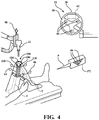
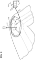
- One such object may be a retractor, such as the retractor assemblies 104 shown in Figure 4 .
- the trackers 110 may be attached to the retractor assemblies 104 by a tracker connector located on the retractor assemblies 104, such as those shown in U.S Patent No. 7,725,162 to Malackowski, et al. , or the trackers 110 may be mounted with conventional fasteners or clamps to fix the trackers 110 to the retractor assemblies 104. Examples of retractor assemblies that may be used are shown in U.S. Patent Application No. 13/554,010 , entitled, "Multi-position Limb Holder", published as U.S. Patent Application Publication No. 2013/0019883 .
- each tracker 110 includes three or more LEDs (not shown) that transmit signals to the camera unit 36 in the same manner as trackers 44, 46, 48.
- the camera unit 36 and/or navigation computer 26 are then able to determine a position of each of the LEDs in the localizer coordinate system LCLZ. While the camera unit 36 is receiving signals from the LEDs on tracker 110, the pointer P is used to touch on several points on the retractor assembly 104 and transmit corresponding signals to the camera unit 36 to determine position information from the pointer P using the pointer tracker PT.
- a virtual constraint boundary can be created that is associated with the retractor assembly 104 and dynamically trackable via the tracker 110.
- the boundary can be created by connecting each of the captured points together. This creates a web or mesh that defines a surface boundary. If only two points are captured, the boundary may be a line between the points. If three points are captured, the boundary may be a triangle formed by lines connecting adjacent points.
- the displays 28, 29 can be used to provide visual feedback of the shape of the boundary created.
- the input devices, e.g., mouse, touch screen, etc. could be used to modify the boundary such as by shifting the boundary, enlarging or shrinking the boundary, changing the shape of the boundary, etc.
- the boundary may be defined in the boundary creation software module as a virtual constraint boundary across which the surgical instrument 22 is prevented from moving in accordance with the robotic control functionality described in U.S.
- the manipulator controller 54 may also continuously track movement of the virtual constraint boundary and continuously adjust a path and/or orientation of the surgical instrument 22 as the virtual constraint boundary moves, to avoid the virtual constraint boundary.
- the virtual constraint boundary can also be tracked simultaneously with tracking of a virtual cutting boundary associated with the femur F or tibia T described in U.S. Provisional Patent Application No. 61/679,258 , entitled, "Surgical Manipulator Capable of Controlling a Surgical Instrument in either a Semi-Autonomous Mode or a Manual, Boundary Constrained Mode,"
- the virtual constraint boundary may move relative to the virtual cutting boundary during the surgery. Tracking of the boundaries would also enable tracking of the relative movement between such boundaries.
- Models of the objects being tracked may be displayed on displays 28, 29 to show the location of the objects. Representations of the virtual boundaries and the anatomy being treated may also be shown on displays 28, 29. Additionally, information relating to the virtual constraint boundaries and virtual cutting boundary can be forwarded to the manipulator controller 54 to guide the manipulator 56 and corresponding movement of the surgical instrument 22 relative to these virtual boundaries so that the surgical instrument 22 does not intrude on the virtual boundaries.
- a virtual boundary is associated with the surgical instrument 22.
- the surgical instrument virtual boundary is tracked via the instrument tracker 48.
- the surgical instrument virtual boundary may be defined merely by a model of the surgical instrument 22.
- the manipulator controller 54 then monitors movement of the surgical instrument virtual boundary relative to the other virtual constraint boundaries, including the virtual cutting boundaries and other virtual constraint boundaries associated with other objects.
- the manipulator controller 54 is then programmed to continuously track movement of the boundaries and update guidance of the surgical instrument 22 as the boundaries move relative to the surgical instrument 22.
- Objects to be avoided by the surgical instrument 22 in the operating room may be tracked indirectly by associating the object with one or more trackers that are not directly fixed to the object.
- the opening 106 in the tissue although not directly attached to a tracker, is formed by the retractor assemblies 104 with trackers 110 fixed thereto. Since the retractor assemblies 104 form the opening 106, there is a general correlation between the size and shape of the opening 106 and the position and orientation of the retractor assemblies 104, which can be tracked by the navigation system 20 using the trackers 110, as described above. Therefore, the opening 106 can also be dynamically tracked.
- the opening 106 can be defined in the boundary creation software module using the points associated with the retractor assemblies 104 since the opening 106 lies along an edge of the retractor assemblies 104.
- the opening 106 can be traced using the pointer P.
- the pointer P is used to capture points defining a periphery of the opening 106 such that the points can be connected in the boundary creation software module to form a ring representing the opening 106.
- the ring may be defined in the boundary creation software module as a virtual constraint boundary to constrain movement of the surgical instrument 22 to within the ring in accordance with the robotic control functionality associated with such openings described in U.S. Provisional Patent Application No.
- 61/679,258 entitled, "Surgical Manipulator Capable of Controlling a Surgical Instrument in either a Semi-Autonomous Mode or a Manual, Boundary Constrained Mode,".
- the opening 106 could additionally be registered to the trackers 110 so that movement of the opening 106 is trackable using the trackers 110.
- Other tissues to be avoided by the surgical instrument 22 such as nerve tissue, ligaments, and the like can similarly be outlined by the pointer P and associated with the trackers 110 to track their movement.
- a leg holder 200 for supporting a leg of a patient is shown.
- the leg holder 200 is described in more detail in U.S. Patent Application No. 13/554,010 , entitled, "Multi-position Limb Holder", published as U.S. Patent Application Publication No. 2013/0019883 .
- An alternative retractor assembly 105 for attaching to the leg holder 200 is shown in Figure 5 .
- the alternative retractor assembly 105 is described in more detail in U.S. Patent Application No. 13/554,010 .
- Retractor heads 107, 109 in Figures 6 and 7 can be used to retract soft tissue to access bone in a surgical procedure. Use of these types of heads 107, 109 for retracting tissue is described in more detail in U.S. Patent Application No. 13/554,010 .
- tracking elements are fixed to the heads 107, 109 so that the heads 107, 109 can be tracked by the navigation system 20. In the embodiment shown, the tracking elements are three or more LEDs 50 that are integrated into the structure of each of the heads 107, 109 and fixed in relationship to one another.
- each head 107, 109 in relation to the LEDs 50 is also stored on the retractor head 107, 109 in memory (not shown) and can be transmitted to the camera unit 36 via transceivers (including transceiver, not shown, integrated into the retractor head 107, 109).
- the model of each head is pre-stored in the navigation computer 26 and accessed during navigation setup by identifying a type or serial no. of the retractor head 107, 109 using the boundary creation software module.
- the shape of each retractor head 107, 109 can also be identified by correlating a unique LED pattern on the retractor head 107, 109 to a database of retractor head shapes.
- the manipulator controller 54 can guide movement of the surgical instrument 22 with respect to the retractor virtual constraint boundaries and the virtual cutting boundaries so that the surgical instrument 22 is not moved beyond these boundaries thereby avoiding inadvertent contact with the retractor assemblies 104 or with bone or other tissue to remain after the surgery.
- These virtual boundaries may be used in both a manual mode and semi-autonomous mode of the surgical manipulator as described in U.S. Provisional Patent Application No. 61/679,258 , entitled, "Surgical Manipulator Capable of Controlling a Surgical Instrument in either a Semi-Autonomous Mode or a Manual, Boundary Constrained Mode,".
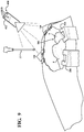
- a flexible shape sensing device 300 may also be used to determine a position of an object, such as opening 106.
- the flexible shape sensing device 300 includes a housing 302 having its own shape sensing coordinate system SS.
- the housing 302 forms part of a reflectometer, such as a Luna Distributed Sensing System commercially available from Luna Innovations Incorporated of Roanoke, Virginia.
- a reflectometer such as a Luna Distributed Sensing System commercially available from Luna Innovations Incorporated of Roanoke, Virginia.
- Another example of a commercially available reflectometer is the Optical Backscatter Reflectometer from Luna Innovations Incorporated.
- a fiber optic cable 304 extends from the housing 302 and is laid on the patient's skin about the opening 106 in close proximity to the opening 106.
- the cable 304 is adhered to the skin in a perimeter with an offset from the opening 106.
- the offset is less than five millimeters from the opening 106 at all locations along the perimeter of the opening 106.
- different offsets may be used or the offsets may be measured after placing the fiber optic cable 304 so that the location of the fiber optic cable 304 relative to the opening 106 is known.
- the cable 304 is flexible so that as the shape of the opening 106 changes, the shape of the cable 304 also changes. Position of the cable 304 is able to be dynamically tracked.
- the flexible shape sensing device 300 including the reflectometer, cable, and other features, and their method of use for determining position are described in U.S. Patent No. 7,772,541 to Froggatt et al.
- Tracking elements such as LEDs 50 may be integrated into the flexible shape sensing device 300.
- a tracker (not shown) can be mounted to the housing 302.
- the LEDs 50 integrated into the flexible shape sensing device 300 transmit signals to the camera unit 36 in the same manner as the LEDs 50 of the trackers 44, 46, 48. Accordingly, the position and orientation of the housing 302 and the shape sensing coordinate system SS can be determining by the navigation system 20 in the localizer coordinate system LCLZ. Movement of the cable 304 results in changes in position in shape sensing coordinate system SS, which is fixed with respect to housing 302. Coordinate system SS is registered to the localizer coordinate system LCLZ using the LEDs 50 on the housing 302. Once registered, changes in position of the cable 304 can also be determined in the localizer coordinate system LCLZ.
- the opening 106 may be defined in the boundary creation software module as a virtual constraint boundary to constrain movement of the surgical instrument 22 to within the opening 106 in accordance with the robotic control functionality associated with such openings described in U.S. Provisional Patent Application No. 61/679,258 , entitled, "Surgical Manipulator Capable of Controlling a Surgical Instrument in either a Semi-Autonomous Mode or a Manual, Boundary Constrained Mode,".
- Other tissues to be avoided by the surgical instrument 22 such as nerve tissue, ligaments, and the like can similarly be tracked using flexible shape sensing devices 300.
- flexible shape sensing devices 300 could be used to establish other boundaries, such as being integrated into gloves worn by the surgical staff so that boundaries associated with surgical personnel can be created.
- Machine vision can identify objects in the operating room and create virtual constraint boundaries associated with the objects.
- Figure 9 shows a machine vision system 400.
- Machine vision system 400 includes a 3-dimensional machine vision camera 402.
- the vision camera 402 is arranged so that a field-of-view of the vision camera 402 encompasses the surgical site and objects in proximity to the surgical site. As shown in Figure 9 , such objects may include the surgical instrument 22 (shown as a cutting bur), retractor assemblies 104, femur F, and tibia T.
- the machine vision system 400 has a control unit (not shown) in communication with the vision camera 402.
- the control unit includes a processor, memory, and storage and is in communication with the navigation computer 26.
- the objects to be tracked are identified.
- the objects may be identified by selecting objects stored in memory on the control unit using machine vision software. For instance, groups of pixels associated with different sizes and shapes of retractor assemblies 104 may be stored in the control unit. By selecting one of the retractor assemblies 104 to be tracked the machine vision software identifies the corresponding group of pixels and the machine vision software then operates to detect like groups of pixels using conventional pattern recognition technology.
- the objects can be identified using an interface in which a user outlines or selects the objects to be tracked on the displays 28, 29. For instance, images taken by the vision camera 402 from overhead the surgical site - similar to the image shown in Figure 9 - are displayed on the displays 28, 29. The user then, using a mouse, digital pen, or the like, traces objects to be tracked on the display 28, 29.
- the machine vision software stores the pixels associated with the object that was traced into its memory. The user identifies each object by a unique identifier such as naming the object "MEDIAL RETRACTOR", etc. in the machine vision software so that the saved group of pixels is now associated with the unique identifier. Multiple objects could be stored in this manner.
- the machine vision system 400 utilizes conventional pattern recognition and associated software to later detect these objects.
- the machine vision system 400 is able to detect movement of these objects by continuously taking images, reviewing the images, and detecting movement of the groups of pixels associated with the objects.
- position information from the control unit of the machine vision system 400 for the objects can be transmitted to the navigation computer 26.
- position information from the navigation computer 26 can be transmitted from the navigation computer 26 to the control unit of the machine vision system 400.
- Control unit of the machine vision system 400 may provide position information for the objects in a machine vision coordinate system MV.
- the vision camera 402 also includes LEDs 50 so that the camera unit 36 can track and thus register the position and orientation of the machine vision coordinate system MV relative to the localizer coordinate system LCLZ.
- position information from the vision camera 402 can be determined in the localizer coordinate system LCLZ.
- Virtual boundaries can thus be associated with the objects in the machine vision system 400 and information relating to these virtual boundaries can be communicated to the navigation computer 26. Additionally, information relating to the virtual constraint boundaries can be forwarded to the manipulator controller 54 to guide the manipulator 56 and corresponding movement of the surgical instrument 22 relative to these virtual boundaries.
- the objects can also be initially registered to the localizer coordinate system LCLZ using the pointer P.
- the pointer P may be used to initially establish virtual constraint boundaries associated with the retractor assemblies 104 when the retractor assemblies 104 are at rest, i.e., not moving. These virtual constraint boundaries would then be stored in the navigation computer 26 and/or manipulator controller 54 for use in guiding the robotic manipulator 56.
- the machine vision system 400 would also be configured to detect movement of the retractor assemblies 104 as previously described, i.e., by tracking movement of the groups of pixels associated with the retractor assemblies 104.
- Machine vision detection of movement of a retractor assembly 104 could then be used to shift the virtual constraint boundary stored in the navigation computer for the retractor assembly 104 by defining a change in pose of the retractor assembly 104 (e.g., translation along 3 axes/rotation about 3 axes).
- the machine vision system 400 would operate to establish a first pose of the retractor assembly 140 at time t1 and a second pose at time t2.
- the difference in pose between t1 and t2 would be provided to the navigation computer 26 and/or manipulator controller 54 to move the associated virtual constraint boundary by a proportional amount in the localizer coordinate system LCLZ.
- only 2-dimensional movement is detected by the vision camera 402 and shared with the navigation computer 26 and/or manipulator controller 54 to update a position of the retractor assembly 104.
- the robotic system is a robotic surgical cutting system for cutting away material from a patient's anatomy, such as bone or soft tissue.
- the cutting system cuts away material to be replaced by surgical implants such as hip and knee implants, including unicompartmental, bicompartmental, or total knee implants.
- surgical implants such as hip and knee implants, including unicompartmental, bicompartmental, or total knee implants.
- the instrument 22 has a cutting tool that is movable in three degrees of freedom relative to a handheld housing and is manually positioned by the hand of the surgeon, without the aid of cutting jigs, guide arms or other constraining mechanism.
- a cutting tool that is movable in three degrees of freedom relative to a handheld housing and is manually positioned by the hand of the surgeon, without the aid of cutting jigs, guide arms or other constraining mechanism.
- Such systems are shown in U.S. Patent Application No. 13/600,888 , entitled, "Surgical Instrument Including Housing, a Cutting Accessory that Extends from the Housing and Actuators that Establish the Position of the Cutting Accessory Relative to the Housing".
- the system includes a hand held surgical cutting instrument having a cutting tool.
- a control system controls movement of the cutting tool in at least three degrees of freedom using internal actuators/motors, as shown in U.S. Patent Application No. 13/600,888 , entitled, "Surgical Instrument Including Housing, a Cutting Accessory that Extends from the Housing and Actuators that Establish the Position of the Cutting Accessory Relative to the Housing".
- the navigation system 20 communicates with the control system.
- One tracker (such as tracker 48) is mounted to the instrument.
- Other trackers (such as trackers 44, 46) are mounted to a patient's anatomy.
- the navigation system 20 communicates with the control system of the hand held surgical cutting instrument.
- the navigation system 20 communicates position and/or orientation data to the control system.
- the position and/or orientation data is indicative of a position and/or orientation of the instrument 22 relative to the anatomy.
- This communication provides closed loop control to control cutting of the anatomy such that the cutting occurs within a predefined boundary (the term predefined boundary is understood to include predefined trajectory, volume, line, other shapes or geometric forms, and the like).
- a 3-D video camera (not shown) is attached to the camera unit 36.
- the video camera is oriented such that a field of view of the camera unit 36 can be associated with the field of view of the video camera.
- the two fields of view may be matched or otherwise correlated such that if an object can be seen in video images streamed from the video camera, the objects are also within the field of view of the camera unit 36.
- a coordinate system of the video camera can also be transformed into the localizer coordinate system LCLZ or vice versa so that positions and/or orientations of objects shown in the video images streamed from the video camera are known in the localizer coordinate system LCLZ.
- Video images from the video camera can be streamed to the displays 28, 29 and the user can then identify on the displays 28, 29, using an input device, such as a mouse or touch screen, virtual constraint boundaries to delineate zones to be avoided by the instrument 22.
- the video images could be provided in 2-D or in 3-D to facilitate the creation of these virtual constraint boundaries.
- Information relating to the positions and/or orientation of these virtual constraint boundaries would be provided into the localizer coordinate system LCLZ and tracked by the navigation computer 26 or manipulator controller 54, for example, to prevent the instrument 22 from intruding on the boundaries created.
- an alarm may be generated.
- the alarm may include visual, tactile, or audible feedback to the user that indicates to the user that the object associated with the virtual constraint boundary is about to be struck and/or may include visual, tactile, or audible indications of distance from the object or associated virtual constraint boundaries.
Description
- The present invention relates generally to systems and computer program products for establishing and tracking virtual boundaries.
- In robotic surgery virtual boundaries are created using computer aided design software to delineate areas in which an end effector of a robotic system can maneuver from areas in which the end effector is restricted. For instance, in orthopedic surgery a virtual cutting boundary may be created to delineate sections of bone to be removed by the end effector during the surgery from sections of bone that are to remain after the surgery.
- A navigation system tracks movement of the end effector with respect to the virtual cutting boundary to determine a position and/or orientation of the end effector relative to the virtual cutting boundary. The robotic system cooperates with the navigation system to guide movement of the end effector so that the end effector does not move beyond the virtual cutting boundary.
- Typically, virtual cutting boundaries are created prior to surgery. Virtual cutting boundaries are often created in a model of a patient's bone and fixed with respect to the bone so that when the model is loaded into the navigation system, the navigation system can track movement of the virtual cutting boundary by tracking movement of the bone.
- Virtual boundaries may define other anatomical features to be avoided by the end effector during surgery. Such features include nerves or other types of tissue to be protected from contact with the end effector. Virtual boundaries are also used to provide virtual pathways that direct the end effector toward the anatomy being treated. These examples of virtual boundaries are often fixed in relationship to the anatomy being treated so that all of the boundaries are tracked together as the anatomy moves. However, some anatomical features or other objects in the operating room may move relative to the anatomy being treated. For instance, retractors used to provide an opening in tissue for the end effector may move relative to the anatomy being treated. If not accurately tracked using an appropriate dynamic virtual constraint boundary, the end effector may inadvertently strike the retractors. As a result, the end effector may be damaged or become inoperative and the retractor may become dislodged from its position.
- Other typically untracked objects may also be in proximity to the end effector that should be avoided by the end effector, yet move relative to the anatomy being treated. Therefore, there is a need in the art for systems and methods for creating dynamic virtual boundaries for such objects.
- Document
WO 2006/091494 A1 discloses a surgical apparatus including a surgical device, configured to be manipulated by a user to perform a procedure on a patient, and a computer system. The computer system is programmed to implement control parameters for controlling the surgical device to provide at least one of haptic guidance to the user and a limit on user manipulation of the surgical device, based on a relationship between an anatomy of the patient and at least one of a position, an orientation, a velocity, and an acceleration of a portion of the surgical device, and to adjust the control parameters in response to movement of the anatomy during the procedure. - Further, document
WO 2006/106419 A2 relates to a system for guiding resurfacing operations on at least a portion of a joint of at least one bone. The system uses a guide with actuators controlled by a computer to position a cutting tool relative to a bone. - Moreover, document
US 2008/214898 A1 discloses a surgical retractor system, in which first and second retractor blades are maintained in spaced relationship by a third retractor blade engaged with the first and second retractor blades. A guidance array adapts the retractor system for use with a surgical navigation system such that the surgical navigation system can determine the position and orientation of blades of the retractor by detecting the position and orientation of the guidance array. - In one embodiment a system is provided that uses a plurality of virtual boundaries to guide movement of an instrument. The system includes an instrument tracking device to track movement of the instrument. The system also includes a first boundary tracking device to track movement of a first of the plurality of virtual boundaries wherein the first virtual boundary is associated with the anatomy to be treated. The system further includes a second boundary tracking device to track movements of a second of the plurality of virtual boundaries wherein the second virtual boundary is associated with a periphery of an opening in a patient to be avoided by the instrument. A controller is configured to receive information associated with the tracking devices including positions of the instrument relative to the first and second virtual boundaries. The controller is configured to guide movement of the instrument relative to each of the first and second virtual boundaries as the first and second virtual boundaries move relative to one another.
- In another embodiment a computer program product comprising software is provided for using a plurality of virtual boundaries to guide movement of an instrument. The software being configured to carry out the step of tracking movement of the instrument and a first virtual boundary associated with the anatomy to be treated. The software further being configured to carry out the step of tracking movement of a second virtual boundary relative to the first virtual boundary wherein the second virtual boundary is associated with a periphery of an opening in a patient to be avoided by the instrument. Movement of the instrument is guided relative to each of the first and second virtual boundaries as the first and second virtual boundaries move relative to one another.
- One advantage of these embodiments is the ability to dynamically track objects (such as other tools or anatomy) that may move relative to the anatomy of interest, in addition to tracking the instrument. The second virtual boundary can be a virtual constraint boundary or other type of virtual boundary that is tracked for movement relative to the first virtual boundary associated with the anatomy.
- Advantages of the present invention will be readily appreciated as the same becomes better understood by reference to the following detailed description when considered in connection with the accompanying drawings wherein:
-
Figure 1 is a perspective view of a navigation system of the present invention being used in conjunction with a robotic system; -
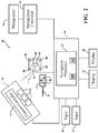
Figure 2 is a schematic view of the navigation system; -
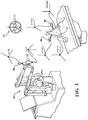
Figure 3 is schematic view of the coordinate systems used in the navigation system; -
Figure 4 is a perspective view of a tissue opening for accessing a knee joint by an end effector of the robotic system; -
Figure 5 is an elevational view of a leg holder and retractor assembly being used to maintain the tissue opening; -
Figure 6 is a top perspective view of a retractor; -
Figure 7 is a top perspective view of an alternative retractor; -
Figure 8 is a top perspective view of the tissue opening showing an end effector in the tissue opening and a flexible shape sensing device for tracking movement of the tissue opening; and -
Figure 9 is a top perspective view of the tissue opening showing an end effector in the tissue opening and a machine vision system for tracking movement of the tissue opening. - Referring to
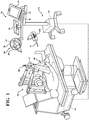
Figure 1 asurgical navigation system 20 is illustrated. Thesystem 20 is shown in a surgical setting such as an operating room of a medical facility. Thenavigation system 20 is set up to track movement of various objects in the operating room. Such objects include, for example, asurgical instrument 22, a femur F of a patient, and a tibia T of the patient. Thenavigation system 20 tracks these objects for purposes of displaying their relative positions and orientations to the surgeon and, in some cases, for purposes of controlling or constraining movement of thesurgical instrument 22 relative to virtual cutting boundaries associated with the femur F and tibia T. - The
surgical navigation system 20 includes acomputer cart assembly 24 that houses anavigation computer 26. A navigation interface is in operative communication with thenavigation computer 26. The navigation interface includes afirst display 28 adapted to be situated outside of the sterile field and asecond display 29 adapted to be situated inside the sterile field. Thedisplays computer cart assembly 24. First andsecond input devices navigation computer 26 or otherwise select/control certain aspects of thenavigation computer 26. Other input devices are contemplated including a touch screen (not shown) or voice-activation. - A
localizer 34 communicates with thenavigation computer 26. In the embodiment shown, thelocalizer 34 is an optical localizer and includes a camera unit 36 (one example of a sensing device). Thecamera unit 36 has anouter casing 38 that houses one or moreoptical position sensors 40. In some embodiments at least twooptical sensors 40 are employed, preferably three. Theoptical sensors 40 may be three separate charge-coupled devices (CCD). In one embodiment three, one-dimensional CCDs are employed. It should be appreciated that in other embodiments, separate camera units, each with a separate CCD, or two or more CCDs, could also be arranged around the operating room. The CCDs detect infrared (IR) signals. -
Camera unit 36 is mounted on an adjustable arm to position theoptical sensors 40 with a field of view of the below discussed trackers that, ideally, is free from obstructions. In some embodiments thecamera unit 36 is adjustable in at least one degree of freedom by rotating about a rotational joint. In other embodiments, thecamera unit 36 is adjustable about two or more degrees of freedom. - The
camera unit 36 includes acamera controller 42 in communication with theoptical sensors 40 to receive signals from theoptical sensors 40. Thecamera controller 42 communicates with thenavigation computer 26 through either a wired or wireless connection (not shown). One such connection may be an IEEE 1394 interface, which is a serial bus interface standard for high-speed communications and isochronous real-time data transfer. The connection could also use a company specific protocol. In other embodiments, theoptical sensors 40 communicate directly with thenavigation computer 26. - Position and orientation signals and/or data are transmitted to the
navigation computer 26 for purposes of tracking objects. Thecomputer cart assembly 24,display 28, andcamera unit 36 may be like those described inU.S. Patent No. 7,725,162 to Malackowski, et al. issued on May 25, 2010 , entitled "Surgery System". - The
navigation computer 26 can be a personal computer or laptop computer.Navigation computer 26 has thedisplay 28, central processing unit (CPU) and/or other processors, memory (not shown), and storage (not shown). Thenavigation computer 26 is loaded with software as described below. The software converts the signals received from thecamera unit 36 into data representative of the position and orientation of the objects being tracked. -
Navigation system 20 includes a plurality of trackingdevices tracker 44 is firmly affixed to the femur F of the patient and anothertracker 46 is firmly affixed to the tibia T of the patient.Trackers Trackers U.S. Patent No. 7,725, 162 .Trackers U.S. Provisional Patent Application No. 61/753,219, filed on January 16, 2013 trackers - An
instrument tracker 48 is firmly attached to thesurgical instrument 22. Theinstrument tracker 48 may be integrated into thesurgical instrument 22 during manufacture or may be separately mounted to thesurgical instrument 22 in preparation for the surgical procedures. The working end of thesurgical instrument 22, which is being tracked by virtue of theinstrument tracker 48, may be a rotating bur, electrical ablation device, or the like. - The
trackers navigation computer 26, which, like thecamera unit 36, preferably receives external power. - In the embodiment shown, the
surgical instrument 22 is attached to a surgical manipulator. Such an arrangement is shown inU.S. Patent Application No. 13/958,070 , entitled, "Surgical Manipulator Capable of Controlling a Surgical Instrument in Multiple Modes". - In other embodiments, the
surgical instrument 22 may be manually positioned by only the hand of the user, without the aid of any cutting guide, jig, or other constraining mechanism such as a manipulator or robot. Such a surgical instrument is described inU.S. Patent Application No. 13/600,888, filed August 31, 2012 - The
optical sensors 40 of thelocalizer 34 receive light signals from thetrackers trackers tracker optical sensors 40. The active markers can be, for example, light emitting diodes orLEDs 50 transmitting light, such as infrared light. Theoptical sensors 40 preferably have sampling rates of 100 Hz or more, more preferably 300 Hz or more, and most preferably 500 Hz or more. In some embodiments, theoptical sensors 40 have sampling rates of 8000 Hz. The sampling rate is the rate at which theoptical sensors 40 receive light signals from sequentially firedLEDs 50. In some embodiments, the light signals from theLEDs 50 are fired at different rates for eachtracker - Referring to
Figure 2 , each of theLEDs 50 are connected to atracker controller 62 located in a housing (not shown) of the associatedtracker navigation computer 26. In one embodiment, thetracker controllers 62 transmit data on the order of several Megabytes/second through wired connections with thenavigation computer 26. In other embodiments, a wireless connection may be used. In these embodiments, thenavigation computer 26 has a transceiver (not shown) to receive the data from thetracker controller 62. - In other embodiments, the
trackers camera unit 36. The reflected light is then received by theoptical sensors 40. Active and passive arrangements are well known in the art. - In some embodiments, the
trackers gyroscope sensor 60 andaccelerometer 70, such as the trackers shown inU.S. Provisional Patent Application No. 61/753,219, filed on January 16, 2013 - The
navigation computer 26 includes anavigation processor 52. It should be understood that thenavigation processor 52 could include one or more processors to control operation of thenavigation computer 26. The processors can be any type of microprocessor or multi-processor system. The term processor is not intended to limit the scope of the invention to a single processor. - The
camera unit 36 receives optical signals from theLEDs 50 of thetrackers processor 52 signals relating to the position of theLEDs 50 of thetrackers localizer 34. Based on the received optical (and non-optical signals in some embodiments),navigation processor 52 generates data indicating the relative positions and orientations of thetrackers localizer 34. - Prior to the start of the surgical procedure, additional data are loaded into the
navigation processor 52. Based on the position and orientation of thetrackers navigation processor 52 determines the position of the working end of thesurgical instrument 22 and the orientation of thesurgical instrument 22 relative to the tissue against which the working end is to be applied. In some embodiments,navigation processor 52 forwards these data to amanipulator controller 54. Themanipulator controller 54 can then use the data to control arobotic manipulator 56 as described inU.S. Provisional Patent Application No. 61/679,258 - The
navigation processor 52 also generates image signals that indicate the relative position of the surgical instrument working end to the tissue. These image signals are applied to thedisplays Displays - Referring to
Figure 3 , tracking of objects is generally conducted with reference to a localizer coordinate system LCLZ. The localizer coordinate system has an origin and an orientation (a set of x-, y-, and z-axes). During the procedure one goal is to keep the localizer coordinate system LCLZ in a known position. An accelerometer (not shown) mounted to thecamera unit 36 may be used to track sudden or unexpected movement of the localizer coordinate system LCLZ, as may occur when thecamera unit 36 is inadvertently bumped by surgical personnel. - Each
tracker navigation system 20 that have their own coordinate systems are thebone trackers instrument tracker 48. These coordinate systems are represented as, respectively, bone tracker coordinate systems BTRK1, BTRK2, and instrument tracker coordinate system TLTR. -
Navigation system 20 monitors the positions of the femur F and tibia T of the patient by monitoring the position ofbone trackers bone trackers - Prior to the start of the procedure, pre-operative images of the femur F and tibia T are generated (or of other tissues in other embodiments). These images may be based on MRI scans, radiological scans or computed tomography (CT) scans of the patient's anatomy. These images are mapped to the femur coordinate system FBONE and tibia coordinate system TBONE using well known methods in the art. These images are fixed in the femur coordinate system FBONE and tibia coordinate system TBONE. As an alternative to taking pre-operative images, plans for treatment can be developed in the operating room (OR) from kinematic studies, bone tracing, and other methods.
- During an initial phase of the procedure, the
bone trackers Figures 1 and2 ), such as disclosed in U.S. - Patent No.
7,725,162 to Malackowski, et al. , hereby incorporated by reference, having its own tracker PT (seeFigure 2 ), may be used to register the femur coordinate system FBONE and tibia coordinate system TBONE to the bone tracker coordinate systems BTRK1 and BTRK2, respectively. Given the fixed relationship between the bones and theirbone trackers camera unit 36 is able to track the femur F and tibia T by tracking thebone trackers manipulator controller 54 andnavigation processor 52. - The working end of the surgical instrument 22 (also referred to as energy applicator distal end) has its own coordinate system EAPP. The origin of the coordinate system EAPP may represent a centroid of a surgical cutting bur, for example. The pose of coordinate system EAPP is fixed to the pose of instrument tracker coordinate system TLTR before the procedure begins. Accordingly, the poses of these coordinate systems EAPP, TLTR relative to each other are determined. The pose-describing data are stored in memory integral with both
manipulator controller 54 andnavigation processor 52. - Referring to
Figure 2 , alocalization engine 100 is a software module that can be considered part of thenavigation system 20. Components of thelocalization engine 100 run onnavigation processor 52. In some versions of the invention, thelocalization engine 100 may run on themanipulator controller 54. -
Localization engine 100 receives as inputs the optically-based signals from thecamera controller 42 and, in some embodiments, the non-optically based signals from thetracker controller 62. Based on these signals,localization engine 100 determines the pose of the bone tracker coordinate systems BTRK1 and BTRK2 in the localizer coordinate system LCLZ. Based on the same signals received for theinstrument tracker 48, thelocalization engine 100 determines the pose of the instrument tracker coordinate system TLTR in the localizer coordinate system LCLZ. - The
localization engine 100 forwards the signals representative of the poses oftrackers transformer 102. Coordinatetransformer 102 is a navigation system software module that runs onnavigation processor 52. Coordinatetransformer 102 references the data that defines the relationship between the pre-operative images of the patient and thebone trackers transformer 102 also stores the data indicating the pose of the working end of the surgical instrument relative to theinstrument tracker 48. - During the procedure, the coordinate
transformer 102 receives the data indicating the relative poses of thetrackers localizer 34. Based on these data and the previously loaded data, the coordinatetransformer 102 generates data indicating the relative position and orientation of both the coordinate system EAPP, and the bone coordinate systems, FBONE and TBONE to the localizer coordinate system LCLZ. - As a result, coordinate
transformer 102 generates data indicating the position and orientation of the working end of thesurgical instrument 22 relative to the tissue (e.g., bone) against which the instrument working end is applied. Image signals representative of these data are forwarded todisplays manipulator controller 54 to guide themanipulator 56 and corresponding movement of thesurgical instrument 22. - Before using the
surgical instrument 22 to treat the patient, certain preparations are necessary such as draping the patient and preparing the surgical site for treatment. For instance, in knee arthroplasty, surgical personnel may secure the leg of interest in a leg holder, and drape the patient and equipment. One such leg holder is shown inU.S. Patent Application No. 13/554,010 , entitled, "Multi-position Limb Holder", published asU.S. Patent Application Publication No. 2013/0019883 . - Other preparations include placing objects needed for surgery in the operating room. Some of these objects are used in proximity to areas in which the
surgical instrument 22 will maneuver. These objects can include leg holders, retractors, suction/irrigation tools, surgical personnel, and the like. During the surgery, these objects are to be avoided by thesurgical instrument 22. To facilitate the avoidance of these objects during the surgery position information for one or more of these objects is determined either directly or indirectly. In some embodiments, one or more of the objects are dynamically tracked by thenavigation system 20 during the surgery. - Referring to
Figure 4 , in one embodiment, position information can be obtained indirectly from an object using the pointer instrument P, an example of which is disclosed inU.S. Patent No. 7,725,162 to Malackowski, et al. The pointer P has its own tracker PT withLEDs 50 that transmit signals to thecamera unit 36 in the same manner astrackers LEDs 50 on the pointer P and stored in the pointer P in electronic format for later transmitting to thecamera unit 36 via transceivers. Alternatively, the position information for the tip is stored in thenavigation computer 26 or calibrated to a known location in the field. In either case, since the tip position is known, the pointer P can be used to determine the positions of objects to be avoided by thesurgical instrument 22. - Once the tip touches certain surfaces of the object, a trigger or switch (not shown) on the pointer P is actuated by the user or alternatively the tip may include a sensor that automatically senses when it is in contact with a surface. A corresponding signal is sent to the transceiver on the
camera unit 36 to read the signals from theLEDs 50 on the pointer tracker PT so that the position of the tip can be calculated, which correlates to a point on the surface of the object. As more points on the surface are touched by the tip and their positions calculated by thenavigation system 20, models of the object can be created to define a position and orientation of the object in the localizer coordinate system LCLZ. Such models can be created using conventional surface mapping tools and the like. - The created models are used as virtual constraint boundaries to guide movement of the
surgical instrument 22. The models may be displayed ondisplays manipulator controller 54 to guide themanipulator 56 and corresponding movement of thesurgical instrument 22 relative to these virtual constraint boundaries to prevent the object from being contacted by thesurgical instrument 22. - When the object is stationary during the surgery the above method of determining position and/or orientation is suitable to provide a virtual constraint boundary, or if the object to be tracked is not stationary, but in a fixed location relative to another tracked object. However, if the object typically moves during the surgery, additional measures are needed to enable continuous tracking of the object. In some embodiments,
mountable trackers 110 may be mounted to the objects. Thesetrackers 110 may be generic with respect to the objects and thus, not be calibrated to the objects. In this case, thetrackers 110 are first attached to the objects. - One such object may be a retractor, such as the
retractor assemblies 104 shown inFigure 4 . Thetrackers 110 may be attached to theretractor assemblies 104 by a tracker connector located on theretractor assemblies 104, such as those shown inU.S Patent No. 7,725,162 to Malackowski, et al. , or thetrackers 110 may be mounted with conventional fasteners or clamps to fix thetrackers 110 to theretractor assemblies 104. Examples of retractor assemblies that may be used are shown inU.S. Patent Application No. 13/554,010 , entitled, "Multi-position Limb Holder", published asU.S. Patent Application Publication No. 2013/0019883 . Once thetracker 110 is fixed to theretractor assembly 104, the pointer P can be used to register the surfaces or other points on theretractor assembly 104. Eachtracker 110 includes three or more LEDs (not shown) that transmit signals to thecamera unit 36 in the same manner astrackers camera unit 36 and/ornavigation computer 26 are then able to determine a position of each of the LEDs in the localizer coordinate system LCLZ. While thecamera unit 36 is receiving signals from the LEDs ontracker 110, the pointer P is used to touch on several points on theretractor assembly 104 and transmit corresponding signals to thecamera unit 36 to determine position information from the pointer P using the pointer tracker PT. This enables thenavigation computer 26 to associate points on theretractor assembly 104 with positions of the LEDs on thetracker 110. Then, through a boundary creation software module (not shown) run by thenavigation processor 52, a virtual constraint boundary can be created that is associated with theretractor assembly 104 and dynamically trackable via thetracker 110. - In some embodiments, the boundary can be created by connecting each of the captured points together. This creates a web or mesh that defines a surface boundary. If only two points are captured, the boundary may be a line between the points. If three points are captured, the boundary may be a triangle formed by lines connecting adjacent points. The
displays surgical instrument 22 is prevented from moving in accordance with the robotic control functionality described inU.S. Provisional Patent Application No. 61/679,258 manipulator controller 54 may also continuously track movement of the virtual constraint boundary and continuously adjust a path and/or orientation of thesurgical instrument 22 as the virtual constraint boundary moves, to avoid the virtual constraint boundary. - The virtual constraint boundary can also be tracked simultaneously with tracking of a virtual cutting boundary associated with the femur F or tibia T described in
U.S. Provisional Patent Application No. 61/679,258 - Models of the objects being tracked may be displayed on
displays displays manipulator controller 54 to guide themanipulator 56 and corresponding movement of thesurgical instrument 22 relative to these virtual boundaries so that thesurgical instrument 22 does not intrude on the virtual boundaries. - In some embodiments, a virtual boundary is associated with the
surgical instrument 22. The surgical instrument virtual boundary is tracked via theinstrument tracker 48. The surgical instrument virtual boundary may be defined merely by a model of thesurgical instrument 22. Themanipulator controller 54 then monitors movement of the surgical instrument virtual boundary relative to the other virtual constraint boundaries, including the virtual cutting boundaries and other virtual constraint boundaries associated with other objects. Themanipulator controller 54 is then programmed to continuously track movement of the boundaries and update guidance of thesurgical instrument 22 as the boundaries move relative to thesurgical instrument 22. - Objects to be avoided by the
surgical instrument 22 in the operating room may be tracked indirectly by associating the object with one or more trackers that are not directly fixed to the object. For instance, inFigure 4 , theopening 106 in the tissue, although not directly attached to a tracker, is formed by theretractor assemblies 104 withtrackers 110 fixed thereto. Since theretractor assemblies 104 form theopening 106, there is a general correlation between the size and shape of theopening 106 and the position and orientation of theretractor assemblies 104, which can be tracked by thenavigation system 20 using thetrackers 110, as described above. Therefore, theopening 106 can also be dynamically tracked. - The
opening 106 can be defined in the boundary creation software module using the points associated with theretractor assemblies 104 since theopening 106 lies along an edge of theretractor assemblies 104. Alternatively, theopening 106 can be traced using the pointer P. In the latter case, the pointer P is used to capture points defining a periphery of theopening 106 such that the points can be connected in the boundary creation software module to form a ring representing theopening 106. The ring may be defined in the boundary creation software module as a virtual constraint boundary to constrain movement of thesurgical instrument 22 to within the ring in accordance with the robotic control functionality associated with such openings described inU.S. Provisional Patent Application No. 61/679,258 opening 106 could additionally be registered to thetrackers 110 so that movement of theopening 106 is trackable using thetrackers 110. Other tissues to be avoided by thesurgical instrument 22 such as nerve tissue, ligaments, and the like can similarly be outlined by the pointer P and associated with thetrackers 110 to track their movement. - Referring to
Figure 5 , aleg holder 200 for supporting a leg of a patient is shown. Theleg holder 200 is described in more detail inU.S. Patent Application No. 13/554,010 , entitled, "Multi-position Limb Holder", published asU.S. Patent Application Publication No. 2013/0019883 . Analternative retractor assembly 105 for attaching to theleg holder 200 is shown inFigure 5 . Thealternative retractor assembly 105 is described in more detail inU.S. Patent Application No. 13/554,010 . - Retractor heads 107, 109 in
Figures 6 and 7 can be used to retract soft tissue to access bone in a surgical procedure. Use of these types ofheads U.S. Patent Application No. 13/554,010 . InFigures 6 and 7 , tracking elements are fixed to theheads heads navigation system 20. In the embodiment shown, the tracking elements are three ormore LEDs 50 that are integrated into the structure of each of theheads head LEDs 50 is also stored on theretractor head camera unit 36 via transceivers (including transceiver, not shown, integrated into theretractor head 107, 109). Alternatively, the model of each head is pre-stored in thenavigation computer 26 and accessed during navigation setup by identifying a type or serial no. of theretractor head retractor head retractor head - By creating virtual constraint boundaries associated with the shapes of the
retractor assemblies 104 and tracking movement of the virtual constraintboundaries using trackers 110 or integrated tracking elements, themanipulator controller 54 can guide movement of thesurgical instrument 22 with respect to the retractor virtual constraint boundaries and the virtual cutting boundaries so that thesurgical instrument 22 is not moved beyond these boundaries thereby avoiding inadvertent contact with theretractor assemblies 104 or with bone or other tissue to remain after the surgery. These virtual boundaries may be used in both a manual mode and semi-autonomous mode of the surgical manipulator as described inU.S. Provisional Patent Application No. 61/679,258 - Referring to
Figure 8 , a flexibleshape sensing device 300 may also be used to determine a position of an object, such asopening 106. The flexibleshape sensing device 300 includes ahousing 302 having its own shape sensing coordinate system SS. Thehousing 302 forms part of a reflectometer, such as a Luna Distributed Sensing System commercially available from Luna Innovations Incorporated of Roanoke, Virginia. Another example of a commercially available reflectometer is the Optical Backscatter Reflectometer from Luna Innovations Incorporated. - A
fiber optic cable 304 extends from thehousing 302 and is laid on the patient's skin about theopening 106 in close proximity to theopening 106. In some embodiments, thecable 304 is adhered to the skin in a perimeter with an offset from theopening 106. In some embodiments, the offset is less than five millimeters from theopening 106 at all locations along the perimeter of theopening 106. In other embodiments, different offsets may be used or the offsets may be measured after placing thefiber optic cable 304 so that the location of thefiber optic cable 304 relative to theopening 106 is known. Thecable 304 is flexible so that as the shape of theopening 106 changes, the shape of thecable 304 also changes. Position of thecable 304 is able to be dynamically tracked. The flexibleshape sensing device 300 including the reflectometer, cable, and other features, and their method of use for determining position are described inU.S. Patent No. 7,772,541 to Froggatt et al. - Tracking elements, such as
LEDs 50 may be integrated into the flexibleshape sensing device 300. Alternatively, a tracker (not shown) can be mounted to thehousing 302. TheLEDs 50 integrated into the flexibleshape sensing device 300 transmit signals to thecamera unit 36 in the same manner as theLEDs 50 of thetrackers housing 302 and the shape sensing coordinate system SS can be determining by thenavigation system 20 in the localizer coordinate system LCLZ. Movement of thecable 304 results in changes in position in shape sensing coordinate system SS, which is fixed with respect tohousing 302. Coordinate system SS is registered to the localizer coordinate system LCLZ using theLEDs 50 on thehousing 302. Once registered, changes in position of thecable 304 can also be determined in the localizer coordinate system LCLZ. - The
opening 106 may be defined in the boundary creation software module as a virtual constraint boundary to constrain movement of thesurgical instrument 22 to within theopening 106 in accordance with the robotic control functionality associated with such openings described inU.S. Provisional Patent Application No. 61/679,258 surgical instrument 22 such as nerve tissue, ligaments, and the like can similarly be tracked using flexibleshape sensing devices 300. Likewise, flexibleshape sensing devices 300 could be used to establish other boundaries, such as being integrated into gloves worn by the surgical staff so that boundaries associated with surgical personnel can be created. - Machine vision can identify objects in the operating room and create virtual constraint boundaries associated with the objects.
Figure 9 shows amachine vision system 400.Machine vision system 400 includes a 3-dimensionalmachine vision camera 402. Thevision camera 402 is arranged so that a field-of-view of thevision camera 402 encompasses the surgical site and objects in proximity to the surgical site. As shown inFigure 9 , such objects may include the surgical instrument 22 (shown as a cutting bur),retractor assemblies 104, femur F, and tibia T. Themachine vision system 400 has a control unit (not shown) in communication with thevision camera 402. The control unit includes a processor, memory, and storage and is in communication with thenavigation computer 26. - Initially, the objects to be tracked are identified. The objects may be identified by selecting objects stored in memory on the control unit using machine vision software. For instance, groups of pixels associated with different sizes and shapes of
retractor assemblies 104 may be stored in the control unit. By selecting one of theretractor assemblies 104 to be tracked the machine vision software identifies the corresponding group of pixels and the machine vision software then operates to detect like groups of pixels using conventional pattern recognition technology. - Alternatively, the objects can be identified using an interface in which a user outlines or selects the objects to be tracked on the
displays vision camera 402 from overhead the surgical site - similar to the image shown inFigure 9 - are displayed on thedisplays display machine vision system 400 utilizes conventional pattern recognition and associated software to later detect these objects. - The
machine vision system 400 is able to detect movement of these objects by continuously taking images, reviewing the images, and detecting movement of the groups of pixels associated with the objects. In some cases, position information from the control unit of themachine vision system 400 for the objects can be transmitted to thenavigation computer 26. Likewise, position information from thenavigation computer 26 can be transmitted from thenavigation computer 26 to the control unit of themachine vision system 400. - Control unit of the
machine vision system 400 may provide position information for the objects in a machine vision coordinate system MV. Thevision camera 402 also includesLEDs 50 so that thecamera unit 36 can track and thus register the position and orientation of the machine vision coordinate system MV relative to the localizer coordinate system LCLZ. Thus, position information from thevision camera 402 can be determined in the localizer coordinate system LCLZ. Virtual boundaries can thus be associated with the objects in themachine vision system 400 and information relating to these virtual boundaries can be communicated to thenavigation computer 26. Additionally, information relating to the virtual constraint boundaries can be forwarded to themanipulator controller 54 to guide themanipulator 56 and corresponding movement of thesurgical instrument 22 relative to these virtual boundaries. - The objects can also be initially registered to the localizer coordinate system LCLZ using the pointer P. For instance, when the
retractor assemblies 104 are not equipped withtrackers 110 or integrated tracking elements, the pointer P may be used to initially establish virtual constraint boundaries associated with theretractor assemblies 104 when theretractor assemblies 104 are at rest, i.e., not moving. These virtual constraint boundaries would then be stored in thenavigation computer 26 and/ormanipulator controller 54 for use in guiding therobotic manipulator 56. Themachine vision system 400 would also be configured to detect movement of theretractor assemblies 104 as previously described, i.e., by tracking movement of the groups of pixels associated with theretractor assemblies 104. - Machine vision detection of movement of a
retractor assembly 104 could then be used to shift the virtual constraint boundary stored in the navigation computer for theretractor assembly 104 by defining a change in pose of the retractor assembly 104 (e.g., translation along 3 axes/rotation about 3 axes). Themachine vision system 400 would operate to establish a first pose of the retractor assembly 140 at time t1 and a second pose at time t2. The difference in pose between t1 and t2 would be provided to thenavigation computer 26 and/ormanipulator controller 54 to move the associated virtual constraint boundary by a proportional amount in the localizer coordinate system LCLZ. In some embodiments, only 2-dimensional movement is detected by thevision camera 402 and shared with thenavigation computer 26 and/ormanipulator controller 54 to update a position of theretractor assembly 104. - In some embodiments, the robotic system is a robotic surgical cutting system for cutting away material from a patient's anatomy, such as bone or soft tissue. Once the cutting system is determined to be in the proper position by the
navigation system 20, the cutting system cuts away material to be replaced by surgical implants such as hip and knee implants, including unicompartmental, bicompartmental, or total knee implants. Some of these types of implants are shown inU.S. Patent Application No. 13/530,927 , entitled, "Prosthetic Implant and Method of Implantation". Thenavigation system 20 instructs the surgeon on proper procedures for locating these implants on bone and securing the implants in position, including the use of trial implants. - In other systems, the
instrument 22 has a cutting tool that is movable in three degrees of freedom relative to a handheld housing and is manually positioned by the hand of the surgeon, without the aid of cutting jigs, guide arms or other constraining mechanism. Such systems are shown inU.S. Patent Application No. 13/600,888 , entitled, "Surgical Instrument Including Housing, a Cutting Accessory that Extends from the Housing and Actuators that Establish the Position of the Cutting Accessory Relative to the Housing". - In these embodiments, the system includes a hand held surgical cutting instrument having a cutting tool. A control system controls movement of the cutting tool in at least three degrees of freedom using internal actuators/motors, as shown in
U.S. Patent Application No. 13/600,888 , entitled, "Surgical Instrument Including Housing, a Cutting Accessory that Extends from the Housing and Actuators that Establish the Position of the Cutting Accessory Relative to the Housing". Thenavigation system 20 communicates with the control system. One tracker (such as tracker 48) is mounted to the instrument. Other trackers (such astrackers 44, 46) are mounted to a patient's anatomy. Thenavigation system 20 communicates with the control system of the hand held surgical cutting instrument. Thenavigation system 20 communicates position and/or orientation data to the control system. The position and/or orientation data is indicative of a position and/or orientation of theinstrument 22 relative to the anatomy. This communication provides closed loop control to control cutting of the anatomy such that the cutting occurs within a predefined boundary (the term predefined boundary is understood to include predefined trajectory, volume, line, other shapes or geometric forms, and the like). - In some embodiments, a 3-D video camera (not shown) is attached to the
camera unit 36. The video camera is oriented such that a field of view of thecamera unit 36 can be associated with the field of view of the video camera. In other words, the two fields of view may be matched or otherwise correlated such that if an object can be seen in video images streamed from the video camera, the objects are also within the field of view of thecamera unit 36. A coordinate system of the video camera can also be transformed into the localizer coordinate system LCLZ or vice versa so that positions and/or orientations of objects shown in the video images streamed from the video camera are known in the localizer coordinate system LCLZ. Video images from the video camera can be streamed to thedisplays displays instrument 22. The video images could be provided in 2-D or in 3-D to facilitate the creation of these virtual constraint boundaries. Information relating to the positions and/or orientation of these virtual constraint boundaries would be provided into the localizer coordinate system LCLZ and tracked by thenavigation computer 26 ormanipulator controller 54, for example, to prevent theinstrument 22 from intruding on the boundaries created. - In some embodiments, when the
manipulator controller 54 ornavigation computer 26 detect that theinstrument 22 is approaching one of the virtual constraint boundaries, an alarm may be generated. The alarm may include visual, tactile, or audible feedback to the user that indicates to the user that the object associated with the virtual constraint boundary is about to be struck and/or may include visual, tactile, or audible indications of distance from the object or associated virtual constraint boundaries. - Several embodiments have been discussed in the foregoing description. However, the embodiments discussed herein are not intended to be exhaustive or limit the invention to any particular form. The terminology which has been used is intended to be in the nature of words of description rather than of limitation. Many modifications and variations are possible in light of the above teachings and the invention may be practiced otherwise than as specifically described.
Claims (17)
- A surgical system (20) comprising:an instrument (22);an instrument tracking device (48) configured to track movement of said instrument (22);a navigation computer (26) configured to create a first virtual boundary associated with an anatomy to be treated by said instrument (22) and being configured to create a second virtual boundary associated with a periphery of a tissue opening (106) for accessing the anatomy to be treated in a patient to be avoided by said instrument (22);a first boundary tracking device (44, 46) configured to be mounted to the anatomy to be treated by said instrument (22);said surgical system (20) being configured to map a pose of a coordinate system of the anatomy to be treated to a coordinate system of the first boundary tracking device (44, 46);a second boundary tracking device (110, 300, 400, P) for tracking the periphery of the tissue opening (106);said navigation computer (26) configured to receive information from said tracking devices (44, 46, 110, 300, 400, P) and to track movement of the first and second virtual boundaries; anda controller (54) configured to receive information associated with said tracking devices (44, 46, 48, 110, 300, 400, P) including positions of said instrument (22) relative to the first and second virtual boundaries, said controller (54) configured to guide movement of said instrument (22) relative to each of the first and second virtual boundaries as the first and second virtual boundaries move relative to one another.
- A system (20) as set forth in claim 1 including a surgical manipulator (56) having a plurality of arms and a plurality of actuators for controlling a position of said instrument (22).
- A system (20) as set forth in claim 2 including a retractor (104, 105) for retracting tissue, said second boundary tracking device (110) being attached to said retractor (104, 105).
- A system (20) as set forth in claim 3 wherein said second boundary tracking device (110, 300, 400, P) includes one of a tracker mountable to said retractor (104, 105) or at least one tracking element (50) integrated into said retractor (104, 105).
- A system (20) as set forth in claim 3 wherein said navigation computer (26) is further configured to create a third virtual boundary associated with a second object to be avoided by said instrument (22), and further including a third boundary tracking device (110, 300, 400, P) provided for the second object to be avoided, said navigation computer (26) being configured to receive information from said third tracking device (110, 300, 400, P) and to track movement of the third virtual boundary, said controller (54) being configured to guide movement of said instrument (22) relative to each of the first, second, and third virtual boundaries.
- A system (20) as set forth in claim 5 wherein said controller (54) is configured to define the opening (106) in the patient for receipt of said instrument (22) based on positions of the second and third virtual boundaries and said controller (54) is configured to monitor a position of the periphery of the opening (106) using said second and third boundary tracking devices (110, 300, 400, P).
- A system (20) as set forth in claim 2 wherein said surgical manipulator (56) is a robotic manipulator (56) operable in manual and semi-autonomous modes.
- A system (20) as set forth in claim 1 wherein said second boundary tracking device (300) includes a flexible shape sensing system comprising a fiber optic cable (304) positionable adjacent the periphery of the opening (106).
- A system (20) as set forth in claim 1 wherein said second boundary tracking device (P) includes a pointer configured to capture points associated with the periphery of the opening (106) so that information relating to the points is used to create the second virtual boundary.
- A system (20) as set forth in claim 1 wherein said second boundary tracking device (400) includes a machine vision system, said machine vision system including a vision camera (402) and a control unit in communication with said controller (54), wherein said machine vision system (402) is configured to detect movement of the periphery of the opening (106).
- A system (20) as set forth in claim 1 wherein each of said tracking devices (44, 46, 48, 110, 300, 400, P) includes one or more tracking elements (50).
- A system (20) as set forth in claim 11 wherein said one or more tracking elements (50) include light emitting diodes.
- A system (20) as set forth in claim 11 wherein said tracking elements (50) include optical tracking elements and said system (20) further includes a plurality of sensing devices (36) to receive optical signals from said optical tracking elements (50).
- A system (20) as set forth in claim 1 wherein said second boundary tracking device (P) includes a pointer configured to capture points associated with the periphery of the opening (106)so that information relating to the points is used to create the second virtual boundary and said system (20) includes a machine vision camera (402) for detecting movement of the periphery of the opening (106), said controller (54) receiving position information derived from images taken by said machine vision camera (402) to adjust a position of the second virtual boundary after the second virtual boundary moves.
- A computer program product comprising software for operating a navigation computer (26) and controller (54) of a surgical system (20), the surgical system (20) comprising an instrument (22), an instrument tracking device (48) configured to track movement of the instrument (22), a first boundary tracking device (44, 46) configured to be mounted to an anatomy to be treated by the instrument (22), a second boundary tracking device (110, 300, 400, P), and an actuator configured to guide movement of the instrument (22), the software being configured to carry out the steps of:creating a first virtual boundary associated with an anatomy to be treated by said instrument (22);creating a second virtual boundary associated with a periphery of a tissue opening (106) for accessing the anatomy to be treated in a patient to be avoided by said instrument (22);mapping a pose of a coordinate system of the anatomy to be treated to a coordinate system of the first boundary tracking device (44, 46);receiving information from the tracking devices (44, 46, 110, 300, 400, P);tracking movement of the instrument (22);tracking movement of the first virtual boundary; andtracking movement of the second virtual boundary relative to the first virtual boundary;controlling the actuator to guide movement of the instrument (22) relative to each of the first and second virtual boundaries.
- A computer program product comprising the software as set forth in claim 15 wherein guiding movement of the instrument (22) relative to the first and second virtual boundaries is further defined as guiding cutting of the anatomy relative to the first virtual boundary and guiding movement of the instrument (22) so that the instrument (22) avoids contact with the periphery of the opening (106) associated with the second virtual boundary.
- A computer program product comprising software as set forth in claim 15, wherein the surgical system (20) further comprises a third boundary tracking device (110, 300, 400, P) for a second object to be avoided, said software being configured to further carry out the steps of:creating a third virtual boundary associated with the second object to be avoided by said instrument (22);receiving information from the third boundary tracking device (110, 300, 400, P);tracking movement of the third virtual boundary; andcontrolling the actuator to guide movement of the instrument (22) relative to each of the first, second, and third virtual boundaries.
Applications Claiming Priority (2)
| Application Number | Priority Date | Filing Date | Title |
|---|---|---|---|
| US201361780148P | 2013-03-13 | 2013-03-13 | |
| PCT/US2014/024269 WO2014165060A2 (en) | 2013-03-13 | 2014-03-12 | Systems and methods for establishing virtual constraint boundaries |
Publications (2)
| Publication Number | Publication Date |
|---|---|
| EP2996611A2 EP2996611A2 (en) | 2016-03-23 |
| EP2996611B1 true EP2996611B1 (en) | 2019-06-26 |
Family
ID=50686121
Family Applications (1)
| Application Number | Title | Priority Date | Filing Date |
|---|---|---|---|
| EP14722833.2A Active EP2996611B1 (en) | 2013-03-13 | 2014-03-12 | Systems and software for establishing virtual constraint boundaries |
Country Status (8)
| Country | Link |
|---|---|
| US (4) | US9603665B2 (en) |
| EP (1) | EP2996611B1 (en) |
| JP (1) | JP6461082B2 (en) |
| KR (1) | KR102060390B1 (en) |
| CN (1) | CN104994805B (en) |
| AU (1) | AU2014248758B2 (en) |
| CA (1) | CA2897873A1 (en) |
| WO (1) | WO2014165060A2 (en) |
Families Citing this family (122)
| Publication number | Priority date | Publication date | Assignee | Title |
|---|---|---|---|---|
| US11871901B2 (en) | 2012-05-20 | 2024-01-16 | Cilag Gmbh International | Method for situational awareness for surgical network or surgical network connected device capable of adjusting function based on a sensed situation or usage |
| US10624710B2 (en) | 2012-06-21 | 2020-04-21 | Globus Medical, Inc. | System and method for measuring depth of instrumentation |
| US10799298B2 (en) | 2012-06-21 | 2020-10-13 | Globus Medical Inc. | Robotic fluoroscopic navigation |
| US11298196B2 (en) | 2012-06-21 | 2022-04-12 | Globus Medical Inc. | Surgical robotic automation with tracking markers and controlled tool advancement |
| US11045267B2 (en) | 2012-06-21 | 2021-06-29 | Globus Medical, Inc. | Surgical robotic automation with tracking markers |
| US11786324B2 (en) | 2012-06-21 | 2023-10-17 | Globus Medical, Inc. | Surgical robotic automation with tracking markers |
| US11857149B2 (en) | 2012-06-21 | 2024-01-02 | Globus Medical, Inc. | Surgical robotic systems with target trajectory deviation monitoring and related methods |
| US11317971B2 (en) | 2012-06-21 | 2022-05-03 | Globus Medical, Inc. | Systems and methods related to robotic guidance in surgery |
| US11589771B2 (en) | 2012-06-21 | 2023-02-28 | Globus Medical Inc. | Method for recording probe movement and determining an extent of matter removed |
| US11963755B2 (en) | 2012-06-21 | 2024-04-23 | Globus Medical Inc. | Apparatus for recording probe movement |
| US11896446B2 (en) | 2012-06-21 | 2024-02-13 | Globus Medical, Inc | Surgical robotic automation with tracking markers |
| US11253327B2 (en) | 2012-06-21 | 2022-02-22 | Globus Medical, Inc. | Systems and methods for automatically changing an end-effector on a surgical robot |
| US11864745B2 (en) | 2012-06-21 | 2024-01-09 | Globus Medical, Inc. | Surgical robotic system with retractor |
| US11857266B2 (en) | 2012-06-21 | 2024-01-02 | Globus Medical, Inc. | System for a surveillance marker in robotic-assisted surgery |
| US11793570B2 (en) | 2012-06-21 | 2023-10-24 | Globus Medical Inc. | Surgical robotic automation with tracking markers |
| US11399900B2 (en) | 2012-06-21 | 2022-08-02 | Globus Medical, Inc. | Robotic systems providing co-registration using natural fiducials and related methods |
| US11864839B2 (en) | 2012-06-21 | 2024-01-09 | Globus Medical Inc. | Methods of adjusting a virtual implant and related surgical navigation systems |
| US9993305B2 (en) * | 2012-08-08 | 2018-06-12 | Ortoma Ab | Method and system for computer assisted surgery |
| US10416624B2 (en) * | 2012-12-13 | 2019-09-17 | University Of Washington Through Its Center For Commercialization | Methods and systems for selecting surgical approaches |
| US9993273B2 (en) | 2013-01-16 | 2018-06-12 | Mako Surgical Corp. | Bone plate and tracking device using a bone plate for attaching to a patient's anatomy |
| AU2014207502B2 (en) | 2013-01-16 | 2018-10-18 | Stryker Corporation | Navigation systems and methods for indicating line-of-sight errors |
| CA2897873A1 (en) | 2013-03-13 | 2014-10-09 | Stryker Corporation | Systems and methods for establishing virtual constraint boundaries |
| JP6626110B2 (en) | 2014-09-04 | 2019-12-25 | メミック イノベーティブ サージェリー リミテッドMemic Innovative Surgery Ltd. | Devices and systems including mechanical arms |
| AU2015337755B2 (en) | 2014-10-29 | 2019-07-25 | Intellijoint Surgical Inc. | Systems, methods and devices for anatomical registration and surgical localization |
| CN107205786B (en) * | 2015-02-25 | 2020-08-25 | 马科外科公司 | Navigation system and method for reducing tracking interruptions during surgical procedures |
| WO2016187290A1 (en) | 2015-05-19 | 2016-11-24 | Mako Surgical Corp. | System and method for manipulating an anatomy |
| KR102523779B1 (en) | 2015-06-09 | 2023-04-20 | 인튜어티브 서지컬 오퍼레이션즈 인코포레이티드 | Construction of a Surgical System with a Surgical Procedure Atlas |
| WO2017037723A1 (en) | 2015-09-04 | 2017-03-09 | Memic Innovative Surgery Ltd. | Actuation of a device comprising mechanical arms |
| KR20180068336A (en) | 2015-11-12 | 2018-06-21 | 인튜어티브 서지컬 오퍼레이션즈 인코포레이티드 | Surgical system with training or auxiliary functions |
| US10405929B1 (en) * | 2015-11-18 | 2019-09-10 | Bradley S. Seltmann | Attachment mechanism for surgical tool tracking system |
| WO2017095870A2 (en) * | 2015-11-30 | 2017-06-08 | Stryker Corporation | Surgical instrument with telescoping nose mechanism |
| CN113925610A (en) * | 2015-12-31 | 2022-01-14 | 史赛克公司 | System and method for performing a procedure on a patient at a target site defined by a virtual object |
| KR102518492B1 (en) * | 2016-01-19 | 2023-04-05 | 타이탄 메디칼 아이엔씨. | Graphical user interface for a robotic surgical system |
| US11883217B2 (en) | 2016-02-03 | 2024-01-30 | Globus Medical, Inc. | Portable medical imaging system and method |
| CA2960354A1 (en) | 2016-03-09 | 2017-09-09 | Memic Innovative Surgery Ltd. | Modular device comprising mechanical arms |
| EP3449859A4 (en) | 2016-04-28 | 2019-05-15 | Sony Corporation | Control device, control method and surgical system |
| US10384353B2 (en) * | 2016-05-16 | 2019-08-20 | Kurion, Inc. | System and method for a robotic manipulator system |
| CA3025300A1 (en) * | 2016-05-23 | 2017-11-30 | Mako Surgical Corp. | Systems and methods for identifying and tracking physical objects during a robotic surgical procedure |
| US10537395B2 (en) | 2016-05-26 | 2020-01-21 | MAKO Surgical Group | Navigation tracker with kinematic connector assembly |
| US10265854B2 (en) * | 2016-08-04 | 2019-04-23 | Synaptive Medical (Barbados) Inc. | Operating room safety zone |
| US11259894B2 (en) * | 2016-09-19 | 2022-03-01 | Neocis, Inc. | Tracking and guidance arrangement for a surgical robot system and related method |
| US11751948B2 (en) | 2016-10-25 | 2023-09-12 | Mobius Imaging, Llc | Methods and systems for robot-assisted surgery |
| KR20180064821A (en) * | 2016-12-06 | 2018-06-15 | 한화에어로스페이스 주식회사 | Apparatus and method for boundary plane setting |
| WO2018112025A1 (en) | 2016-12-16 | 2018-06-21 | Mako Surgical Corp. | Techniques for modifying tool operation in a surgical robotic system based on comparing actual and commanded states of the tool relative to a surgical site |
| EP3369394B1 (en) * | 2017-03-03 | 2020-06-10 | Globus Medical, Inc. | System for a surveillance marker in robotic-assisted surgery |
| US10973592B2 (en) | 2017-03-09 | 2021-04-13 | Memie Innovative Surgery Ltd. | Control console for surgical device with mechanical arms |
| US11779410B2 (en) | 2017-03-09 | 2023-10-10 | Momentis Surgical Ltd | Control console including an input arm for control of a surgical mechanical arm |
| US11432898B2 (en) * | 2017-03-14 | 2022-09-06 | Intellijoint Surgical Inc. | Tracing platforms and intra-operative systems and methods using same |
| US10716627B2 (en) * | 2017-05-03 | 2020-07-21 | Covidien Lp | Method and system for planning a surgical instrument path |
| US11253329B2 (en) | 2017-06-09 | 2022-02-22 | Mako Surgical Corp. | Robotic surgical system and method for producing reactive forces to implement virtual boundaries |
| US20190069957A1 (en) * | 2017-09-06 | 2019-03-07 | Verily Life Sciences Llc | Surgical recognition system |
| US20190090960A1 (en) * | 2017-09-25 | 2019-03-28 | Intuitive Surgical Operations, Inc. | Tubular body structure imaging and locating system |
| US11026712B2 (en) | 2017-10-30 | 2021-06-08 | Cilag Gmbh International | Surgical instruments comprising a shifting mechanism |
| US11801098B2 (en) | 2017-10-30 | 2023-10-31 | Cilag Gmbh International | Method of hub communication with surgical instrument systems |
| US11911045B2 (en) | 2017-10-30 | 2024-02-27 | Cllag GmbH International | Method for operating a powered articulating multi-clip applier |
| US11129679B2 (en) * | 2017-11-14 | 2021-09-28 | Mako Surgical Corp. | Fiber optic tracking system |
| US10555781B2 (en) * | 2017-11-15 | 2020-02-11 | Stryker Corporation | High bandwidth and low latency hybrid communication techniques for a navigation system |
| CN107997822B (en) * | 2017-12-06 | 2021-03-19 | 上海卓梦医疗科技有限公司 | Minimally invasive surgery positioning system |
| US11937769B2 (en) | 2017-12-28 | 2024-03-26 | Cilag Gmbh International | Method of hub communication, processing, storage and display |
| US11389164B2 (en) | 2017-12-28 | 2022-07-19 | Cilag Gmbh International | Method of using reinforced flexible circuits with multiple sensors to optimize performance of radio frequency devices |
| US11612444B2 (en) | 2017-12-28 | 2023-03-28 | Cilag Gmbh International | Adjustment of a surgical device function based on situational awareness |
| US11896322B2 (en) | 2017-12-28 | 2024-02-13 | Cilag Gmbh International | Sensing the patient position and contact utilizing the mono-polar return pad electrode to provide situational awareness to the hub |
| US11771487B2 (en) | 2017-12-28 | 2023-10-03 | Cilag Gmbh International | Mechanisms for controlling different electromechanical systems of an electrosurgical instrument |
| US11202570B2 (en) | 2017-12-28 | 2021-12-21 | Cilag Gmbh International | Communication hub and storage device for storing parameters and status of a surgical device to be shared with cloud based analytics systems |
| US11666331B2 (en) | 2017-12-28 | 2023-06-06 | Cilag Gmbh International | Systems for detecting proximity of surgical end effector to cancerous tissue |
| US11166772B2 (en) | 2017-12-28 | 2021-11-09 | Cilag Gmbh International | Surgical hub coordination of control and communication of operating room devices |
| US11672605B2 (en) | 2017-12-28 | 2023-06-13 | Cilag Gmbh International | Sterile field interactive control displays |
| US11744604B2 (en) | 2017-12-28 | 2023-09-05 | Cilag Gmbh International | Surgical instrument with a hardware-only control circuit |
| US10758310B2 (en) | 2017-12-28 | 2020-09-01 | Ethicon Llc | Wireless pairing of a surgical device with another device within a sterile surgical field based on the usage and situational awareness of devices |
| US11864728B2 (en) | 2017-12-28 | 2024-01-09 | Cilag Gmbh International | Characterization of tissue irregularities through the use of mono-chromatic light refractivity |
| US11013563B2 (en) | 2017-12-28 | 2021-05-25 | Ethicon Llc | Drive arrangements for robot-assisted surgical platforms |
| US10595887B2 (en) | 2017-12-28 | 2020-03-24 | Ethicon Llc | Systems for adjusting end effector parameters based on perioperative information |
| US11109866B2 (en) | 2017-12-28 | 2021-09-07 | Cilag Gmbh International | Method for circular stapler control algorithm adjustment based on situational awareness |
| US20190201142A1 (en) * | 2017-12-28 | 2019-07-04 | Ethicon Llc | Automatic tool adjustments for robot-assisted surgical platforms |
| US11832899B2 (en) | 2017-12-28 | 2023-12-05 | Cilag Gmbh International | Surgical systems with autonomously adjustable control programs |
| US11896443B2 (en) | 2017-12-28 | 2024-02-13 | Cilag Gmbh International | Control of a surgical system through a surgical barrier |
| US11786251B2 (en) | 2017-12-28 | 2023-10-17 | Cilag Gmbh International | Method for adaptive control schemes for surgical network control and interaction |
| US11678881B2 (en) | 2017-12-28 | 2023-06-20 | Cilag Gmbh International | Spatial awareness of surgical hubs in operating rooms |
| US11857152B2 (en) | 2017-12-28 | 2024-01-02 | Cilag Gmbh International | Surgical hub spatial awareness to determine devices in operating theater |
| US11818052B2 (en) | 2017-12-28 | 2023-11-14 | Cilag Gmbh International | Surgical network determination of prioritization of communication, interaction, or processing based on system or device needs |
| US11132462B2 (en) | 2017-12-28 | 2021-09-28 | Cilag Gmbh International | Data stripping method to interrogate patient records and create anonymized record |
| US11903601B2 (en) | 2017-12-28 | 2024-02-20 | Cilag Gmbh International | Surgical instrument comprising a plurality of drive systems |
| WO2019173600A1 (en) * | 2018-03-07 | 2019-09-12 | Think Surgical, Inc. | Workflow control with tracked devices |
| US11464532B2 (en) | 2018-03-08 | 2022-10-11 | Cilag Gmbh International | Methods for estimating and controlling state of ultrasonic end effector |
| US11259830B2 (en) | 2018-03-08 | 2022-03-01 | Cilag Gmbh International | Methods for controlling temperature in ultrasonic device |
| US11090047B2 (en) | 2018-03-28 | 2021-08-17 | Cilag Gmbh International | Surgical instrument comprising an adaptive control system |
| US10842699B2 (en) * | 2018-04-27 | 2020-11-24 | Ormonde M. Mahoney | System and method for patient positioning in an automated surgery |
| CN108478281A (en) * | 2018-05-08 | 2018-09-04 | 昆明医科大学第附属医院 | A kind of orthopedic navigation system |
| US11026752B2 (en) | 2018-06-04 | 2021-06-08 | Medtronic Navigation, Inc. | System and method for performing and evaluating a procedure |
| US11510737B2 (en) | 2018-06-21 | 2022-11-29 | Mako Surgical Corp. | Patella tracking |
| JP7360406B2 (en) * | 2018-06-26 | 2023-10-12 | ファナック アメリカ コーポレイション | Augmented reality visualization for robotic picking systems |
| CN110652360B (en) * | 2018-06-29 | 2023-03-14 | 格罗伯斯医疗有限公司 | Surgical robot automation with tracking markers |
| US11291507B2 (en) * | 2018-07-16 | 2022-04-05 | Mako Surgical Corp. | System and method for image based registration and calibration |
| US11298186B2 (en) * | 2018-08-02 | 2022-04-12 | Point Robotics Medtech Inc. | Surgery assistive system and method for obtaining surface information thereof |
| US11612438B2 (en) | 2018-09-05 | 2023-03-28 | Point Robotics Medtech Inc. | Navigation system and method for medical operation by a robotic system using a tool |
| CN113016038A (en) * | 2018-10-12 | 2021-06-22 | 索尼集团公司 | Haptic obstruction to avoid collisions with robotic surgical equipment |
| JP7407442B2 (en) | 2019-01-15 | 2024-01-04 | インテリジョイント サージカル インク. | Systems, devices, and computer-implemented methods for bone reorientation |
| US11291445B2 (en) | 2019-02-19 | 2022-04-05 | Cilag Gmbh International | Surgical staple cartridges with integral authentication keys |
| AU2020241316A1 (en) | 2019-03-15 | 2021-10-07 | Mako Surgical Corp. | Robotic surgical system and methods utilizing a cutting bur for bone penetration and cannulation |
| US11690680B2 (en) | 2019-03-19 | 2023-07-04 | Mako Surgical Corp. | Trackable protective packaging for tools and methods for calibrating tool installation using the same |
| EP3711699B1 (en) | 2019-03-21 | 2024-01-03 | Stryker European Operations Limited | Technique for transferring a registration of image data of a surgical object from one surgical navigation system to another surgical navigation system |
| USD940736S1 (en) | 2019-11-20 | 2022-01-11 | Titan Medical Inc. | Display screen or portion thereof with a graphical user interface |
| US11382699B2 (en) | 2020-02-10 | 2022-07-12 | Globus Medical Inc. | Extended reality visualization of optical tool tracking volume for computer assisted navigation in surgery |
| JP7439602B2 (en) | 2020-03-23 | 2024-02-28 | Toppanホールディングス株式会社 | Visualization device, visualization method, and program |
| AU2021241577A1 (en) | 2020-03-27 | 2022-11-03 | Mako Surgical Corp. | Systems and methods for controlling robotic movement of a tool based on a virtual boundary |
| WO2022024130A2 (en) * | 2020-07-31 | 2022-02-03 | Mazor Robotics Ltd. | Object detection and avoidance in a surgical setting |
| US11931113B2 (en) | 2020-08-03 | 2024-03-19 | Mazor Robotics Ltd. | Systems, devices, and methods for retractor interference avoidance |
| CN114601564B (en) * | 2020-10-08 | 2023-08-22 | 深圳市精锋医疗科技股份有限公司 | Surgical robot, graphical control device thereof and graphical display method thereof |
| US20240029858A1 (en) * | 2020-12-01 | 2024-01-25 | Intuitive Surgical Operations, Inc. | Systems and methods for generating and evaluating a medical procedure |
| JP2022088805A (en) | 2020-12-03 | 2022-06-15 | 株式会社メディカロイド | Robot surgery system and display method |
| EP4011312B1 (en) * | 2020-12-10 | 2023-08-23 | DePuy Ireland Unlimited Company | Robotic surgical system |
| CN112998863B (en) * | 2021-03-12 | 2022-05-06 | 杭州柳叶刀机器人有限公司 | Robot safety boundary interaction device, electronic apparatus, and storage medium |
| US11819302B2 (en) | 2021-03-31 | 2023-11-21 | Moon Surgical Sas | Co-manipulation surgical system having user guided stage control |
| US11832909B2 (en) | 2021-03-31 | 2023-12-05 | Moon Surgical Sas | Co-manipulation surgical system having actuatable setup joints |
| US11844583B2 (en) | 2021-03-31 | 2023-12-19 | Moon Surgical Sas | Co-manipulation surgical system having an instrument centering mode for automatic scope movements |
| US11812938B2 (en) | 2021-03-31 | 2023-11-14 | Moon Surgical Sas | Co-manipulation surgical system having a coupling mechanism removeably attachable to surgical instruments |
| CA3212211A1 (en) | 2021-03-31 | 2022-10-06 | David Paul Noonan | Co-manipulation surgical system for use with surgical instruments for performing laparoscopic surgery |
| US20230020476A1 (en) * | 2021-07-15 | 2023-01-19 | Mazor Robotics Ltd. | Path planning based on work volume mapping |
| US20230210579A1 (en) * | 2021-12-30 | 2023-07-06 | Verb Surgical Inc. | Real-time surgical tool presence/absence detection in surgical videos |
| US20230390001A1 (en) | 2022-06-03 | 2023-12-07 | Mako Surgical Corp | Surgical robotic system with compliance mechanism |
| WO2024044365A1 (en) | 2022-08-26 | 2024-02-29 | Mako Surgical Corp. | Selectively automated robotic surgical system |
| US11832910B1 (en) | 2023-01-09 | 2023-12-05 | Moon Surgical Sas | Co-manipulation surgical system having adaptive gravity compensation |
Family Cites Families (199)
| Publication number | Priority date | Publication date | Assignee | Title |
|---|---|---|---|---|
| US6347240B1 (en) | 1990-10-19 | 2002-02-12 | St. Louis University | System and method for use in displaying images of a body part |
| US6675040B1 (en) * | 1991-01-28 | 2004-01-06 | Sherwood Services Ag | Optical object tracking system |
| US6405072B1 (en) * | 1991-01-28 | 2002-06-11 | Sherwood Services Ag | Apparatus and method for determining a location of an anatomical target with reference to a medical apparatus |
| US5662111A (en) | 1991-01-28 | 1997-09-02 | Cosman; Eric R. | Process of stereotactic optical navigation |
| US5279309A (en) | 1991-06-13 | 1994-01-18 | International Business Machines Corporation | Signaling device and method for monitoring positions in a surgical operation |
| US6963792B1 (en) | 1992-01-21 | 2005-11-08 | Sri International | Surgical method |
| US6788999B2 (en) | 1992-01-21 | 2004-09-07 | Sri International, Inc. | Surgical system |
| US5603318A (en) | 1992-04-21 | 1997-02-18 | University Of Utah Research Foundation | Apparatus and method for photogrammetric surgical localization |
| US5517990A (en) | 1992-11-30 | 1996-05-21 | The Cleveland Clinic Foundation | Stereotaxy wand and tool guide |
| US5623582A (en) | 1994-07-14 | 1997-04-22 | Immersion Human Interface Corporation | Computer interface or control input device for laparoscopic surgical instrument and other elongated mechanical objects |
| US5803089A (en) | 1994-09-15 | 1998-09-08 | Visualization Technology, Inc. | Position tracking and imaging system for use in medical applications |
| US6646541B1 (en) | 1996-06-24 | 2003-11-11 | Computer Motion, Inc. | General purpose distributed operating room control system |
| US5695501A (en) | 1994-09-30 | 1997-12-09 | Ohio Medical Instrument Company, Inc. | Apparatus for neurosurgical stereotactic procedures |
| US5891157A (en) | 1994-09-30 | 1999-04-06 | Ohio Medical Instrument Company, Inc. | Apparatus for surgical stereotactic procedures |
| US6978166B2 (en) | 1994-10-07 | 2005-12-20 | Saint Louis University | System for use in displaying images of a body part |
| DE69532829T2 (en) | 1994-10-07 | 2005-01-27 | St. Louis University | DEVICE FOR USE WITH A SURGICAL NAVIGATION SYSTEM |
| US5882206A (en) | 1995-03-29 | 1999-03-16 | Gillio; Robert G. | Virtual surgery system |
| US5814038A (en) | 1995-06-07 | 1998-09-29 | Sri International | Surgical manipulator for a telerobotic system |
| US5649956A (en) | 1995-06-07 | 1997-07-22 | Sri International | System and method for releasably holding a surgical instrument |
| US5820623A (en) | 1995-06-20 | 1998-10-13 | Ng; Wan Sing | Articulated arm for medical procedures |
| JPH0970780A (en) | 1995-09-06 | 1997-03-18 | Fanuc Ltd | Tool shape correcting method of robot |
| US7445594B1 (en) * | 1995-09-20 | 2008-11-04 | Medtronic, Inc. | Method and apparatus for temporarily immobilizing a local area of tissue |
| US6351659B1 (en) | 1995-09-28 | 2002-02-26 | Brainlab Med. Computersysteme Gmbh | Neuro-navigation system |
| US5682886A (en) | 1995-12-26 | 1997-11-04 | Musculographics Inc | Computer-assisted surgical system |
| US6436107B1 (en) | 1996-02-20 | 2002-08-20 | Computer Motion, Inc. | Method and apparatus for performing minimally invasive surgical procedures |
| US6063095A (en) | 1996-02-20 | 2000-05-16 | Computer Motion, Inc. | Method and apparatus for performing minimally invasive surgical procedures |
| US5855583A (en) | 1996-02-20 | 1999-01-05 | Computer Motion, Inc. | Method and apparatus for performing minimally invasive cardiac procedures |
| US5971976A (en) | 1996-02-20 | 1999-10-26 | Computer Motion, Inc. | Motion minimization and compensation system for use in surgical procedures |
| US6699177B1 (en) | 1996-02-20 | 2004-03-02 | Computer Motion, Inc. | Method and apparatus for performing minimally invasive surgical procedures |
| US5952796A (en) | 1996-02-23 | 1999-09-14 | Colgate; James E. | Cobots |
| WO1997034744A2 (en) | 1996-03-21 | 1997-09-25 | Newnes Machine Ltd. | Position-based integrated motion controlled curve sawing |
| US6017354A (en) | 1996-08-15 | 2000-01-25 | Stryker Corporation | Integrated system for powered surgical tools |
| US6024576A (en) | 1996-09-06 | 2000-02-15 | Immersion Corporation | Hemispherical, high bandwidth mechanical interface for computer systems |
| US6331116B1 (en) | 1996-09-16 | 2001-12-18 | The Research Foundation Of State University Of New York | System and method for performing a three-dimensional virtual segmentation and examination |
| US5824085A (en) | 1996-09-30 | 1998-10-20 | Integrated Surgical Systems, Inc. | System and method for cavity generation for surgical planning and initial placement of a bone prosthesis |
| US5880976A (en) | 1997-02-21 | 1999-03-09 | Carnegie Mellon University | Apparatus and method for facilitating the implantation of artificial components in joints |
| US6205411B1 (en) | 1997-02-21 | 2001-03-20 | Carnegie Mellon University | Computer-assisted surgery planner and intra-operative guidance system |
| DE29704393U1 (en) | 1997-03-11 | 1997-07-17 | Aesculap Ag | Device for preoperative determination of the position data of endoprosthesis parts |
| JPH11156672A (en) | 1997-08-25 | 1999-06-15 | Yoshiaki Kakino | Numerical control device, and machine tool having it |
| US6097168A (en) | 1997-08-25 | 2000-08-01 | Toshiba Kikai Kabushiki Kaisha | Position control apparatus and method of the same, numerical control program preparation apparatus and method of the same, and methods of controlling numerical control machine tool |
| WO1999010137A1 (en) | 1997-08-28 | 1999-03-04 | Microdexterity Systems | Parallel mechanism |
| WO1999029474A2 (en) | 1997-12-06 | 1999-06-17 | Elan Schaltelemente Gmbh & Co. Kg | Monitoring and control device for monitoring a technical facility subject to enhanced safety requirements, especially a handling device |
| US6228089B1 (en) * | 1997-12-19 | 2001-05-08 | Depuy International Limited | Device for positioning and guiding a surgical instrument during orthopaedic interventions |
| WO1999037220A1 (en) | 1998-01-23 | 1999-07-29 | Sm Scienzia Machinale S.R.L. | Orthopaedic surgery apparatus for guiding a tool and for supporting a limb |
| US6810281B2 (en) * | 2000-12-21 | 2004-10-26 | Endovia Medical, Inc. | Medical mapping system |
| US6692485B1 (en) | 1998-02-24 | 2004-02-17 | Endovia Medical, Inc. | Articulated apparatus for telemanipulator system |
| DE19814630B4 (en) | 1998-03-26 | 2011-09-29 | Carl Zeiss | Method and apparatus for manually controlled guiding a tool in a predetermined range of motion |
| US6157873A (en) | 1998-04-09 | 2000-12-05 | Motoman, Inc. | Robot programming system and method |
| US6233504B1 (en) | 1998-04-16 | 2001-05-15 | California Institute Of Technology | Tool actuation and force feedback on robot-assisted microsurgery system |
| AU3924599A (en) | 1998-05-28 | 1999-12-13 | Orthosoft, Inc. | Interactive computer-assisted surgical system and method thereof |
| US6421048B1 (en) | 1998-07-17 | 2002-07-16 | Sensable Technologies, Inc. | Systems and methods for interacting with virtual objects in a haptic virtual reality environment |
| US6552722B1 (en) * | 1998-07-17 | 2003-04-22 | Sensable Technologies, Inc. | Systems and methods for sculpting virtual objects in a haptic virtual reality environment |
| US6117143A (en) | 1998-09-11 | 2000-09-12 | Hybex Surgical Specialties, Inc. | Apparatus for frameless stereotactic surgery |
| US6311100B1 (en) | 1998-09-14 | 2001-10-30 | Mass. Institute Of Technology | Tool path generator for computer aided manufacturing |
| US6033415A (en) | 1998-09-14 | 2000-03-07 | Integrated Surgical Systems | System and method for performing image directed robotic orthopaedic procedures without a fiducial reference system |
| DE19846687C2 (en) | 1998-10-09 | 2001-07-26 | Auer Dorothee | Auxiliary surgical device for use in performing medical procedures and methods for generating an image in the context of medical procedures |
| US6195618B1 (en) | 1998-10-15 | 2001-02-27 | Microscribe, Llc | Component position verification using a probe apparatus |
| US6704694B1 (en) | 1998-10-16 | 2004-03-09 | Massachusetts Institute Of Technology | Ray based interaction system |
| WO2000028882A2 (en) | 1998-11-18 | 2000-05-25 | Microdexterity Systems, Inc. | Medical manipulator for use with an imaging device |
| DE69918569T2 (en) | 1998-11-23 | 2005-03-24 | Microdexterity Systems Inc., Memphis | SURGICAL MANIPULATOR |
| US6522906B1 (en) | 1998-12-08 | 2003-02-18 | Intuitive Surgical, Inc. | Devices and methods for presenting and regulating auxiliary information on an image display of a telesurgical system to assist an operator in performing a surgical procedure |
| US6322567B1 (en) | 1998-12-14 | 2001-11-27 | Integrated Surgical Systems, Inc. | Bone motion tracking system |
| US6430434B1 (en) | 1998-12-14 | 2002-08-06 | Integrated Surgical Systems, Inc. | Method for determining the location and orientation of a bone for computer-assisted orthopedic procedures using intraoperatively attached markers |
| US6501981B1 (en) * | 1999-03-16 | 2002-12-31 | Accuray, Inc. | Apparatus and method for compensating for respiratory and patient motions during treatment |
| US6466815B1 (en) * | 1999-03-30 | 2002-10-15 | Olympus Optical Co., Ltd. | Navigation apparatus and surgical operation image acquisition/display apparatus using the same |
| DE19914455B4 (en) | 1999-03-30 | 2005-07-14 | Siemens Ag | Method for determining the movement of an organ or therapeutic area of a patient and a system suitable for this purpose |
| DE19915060A1 (en) | 1999-04-01 | 2000-11-02 | Erbe Elektromedizin | Surgical instrument |
| US7084867B1 (en) | 1999-04-02 | 2006-08-01 | Massachusetts Institute Of Technology | Haptic interface system for collision detection and applications therefore |
| US6304050B1 (en) | 1999-07-19 | 2001-10-16 | Steven B. Skaar | Means and method of robot control relative to an arbitrary surface using camera-space manipulation |
| DE19946948A1 (en) | 1999-09-30 | 2001-04-05 | Philips Corp Intellectual Pty | Method and arrangement for determining the position of a medical instrument |
| US7366562B2 (en) | 2003-10-17 | 2008-04-29 | Medtronic Navigation, Inc. | Method and apparatus for surgical navigation |
| US20010034530A1 (en) | 2000-01-27 | 2001-10-25 | Malackowski Donald W. | Surgery system |
| DE10004764A1 (en) | 2000-02-03 | 2001-08-09 | Philips Corp Intellectual Pty | Method for determining the position of a medical instrument |
| WO2001062173A2 (en) | 2000-02-25 | 2001-08-30 | The Board Of Trustees Of The Leland Stanford Junior University | Methods and apparatuses for maintaining a trajectory in sterotaxi for tracking a target inside a body |
| US6711432B1 (en) | 2000-10-23 | 2004-03-23 | Carnegie Mellon University | Computer-aided orthopedic surgery |
| US6535756B1 (en) | 2000-04-07 | 2003-03-18 | Surgical Navigation Technologies, Inc. | Trajectory storage apparatus and method for surgical navigation system |
| US6336931B1 (en) | 2000-05-17 | 2002-01-08 | Yeh-Liang Hsu | Automatic bone drilling apparatus for surgery operation |
| GB0015683D0 (en) | 2000-06-28 | 2000-08-16 | Depuy Int Ltd | Apparatus for positioning a surgical instrument |
| US6837892B2 (en) | 2000-07-24 | 2005-01-04 | Mazor Surgical Technologies Ltd. | Miniature bone-mounted surgical robot |
| US6494882B1 (en) | 2000-07-25 | 2002-12-17 | Verimetra, Inc. | Cutting instrument having integrated sensors |
| US6902560B1 (en) | 2000-07-27 | 2005-06-07 | Intuitive Surgical, Inc. | Roll-pitch-roll surgical tool |
| EP1365686A4 (en) | 2000-09-23 | 2009-12-02 | Ramin Shahidi | Endoscopic targeting method and system |
| DE10047698A1 (en) | 2000-09-25 | 2002-04-11 | Zeiss Carl | Medical therapy and / or diagnostic device with a position detection device |
| JP4014792B2 (en) | 2000-09-29 | 2007-11-28 | 株式会社東芝 | manipulator |
| US7892243B2 (en) | 2001-01-16 | 2011-02-22 | Microdexterity Systems, Inc. | Surgical manipulator |
| AU2002248360A1 (en) | 2001-01-16 | 2002-08-19 | Microdexterity Systems, Inc. | Surgical manipulator |
| WO2002060330A1 (en) | 2001-01-29 | 2002-08-08 | Stephen Ritland | Retractor and method for spinal pedicle screw placement |
| US7035716B2 (en) | 2001-01-29 | 2006-04-25 | The Acrobot Company Limited | Active-constraint robots |
| US6929606B2 (en) | 2001-01-29 | 2005-08-16 | Depuy Spine, Inc. | Retractor and method for spinal pedicle screw placement |
| US6514259B2 (en) * | 2001-02-02 | 2003-02-04 | Carnegie Mellon University | Probe and associated system and method for facilitating planar osteotomy during arthoplasty |
| US20030135204A1 (en) | 2001-02-15 | 2003-07-17 | Endo Via Medical, Inc. | Robotically controlled medical instrument with a flexible section |
| DE10108547B4 (en) | 2001-02-22 | 2006-04-20 | Siemens Ag | Operating system for controlling surgical instruments based on intra-operative X-ray images |
| WO2002067800A2 (en) | 2001-02-27 | 2002-09-06 | Smith & Nephew, Inc. | Surgical navigation systems and processes for high tibial osteotomy |
| DE10110093A1 (en) | 2001-03-02 | 2002-09-26 | Juergen Wahrburg | Device for displaying the spatial position of a surgical instrument during an operation and for comparison of actual and theoretical positions so that a correction signal can be generated |
| CN100556370C (en) | 2001-03-26 | 2009-11-04 | Lb医药有限公司 | Be used for material is excised or the method and apparatus system of processed |
| US7056123B2 (en) | 2001-07-16 | 2006-06-06 | Immersion Corporation | Interface apparatus with cable-driven force feedback and grounded actuators |
| US6728599B2 (en) | 2001-09-07 | 2004-04-27 | Computer Motion, Inc. | Modularity system for computer assisted surgery |
| US6785572B2 (en) | 2001-11-21 | 2004-08-31 | Koninklijke Philips Electronics, N.V. | Tactile feedback and display in a CT image guided robotic system for interventional procedures |
| US6793653B2 (en) | 2001-12-08 | 2004-09-21 | Computer Motion, Inc. | Multifunctional handle for a medical robotic system |
| US7831292B2 (en) | 2002-03-06 | 2010-11-09 | Mako Surgical Corp. | Guidance system and method for surgical procedures with improved feedback |
| US7206627B2 (en) | 2002-03-06 | 2007-04-17 | Z-Kat, Inc. | System and method for intra-operative haptic planning of a medical procedure |
| US8010180B2 (en) | 2002-03-06 | 2011-08-30 | Mako Surgical Corp. | Haptic guidance system and method |
| US9155544B2 (en) * | 2002-03-20 | 2015-10-13 | P Tech, Llc | Robotic systems and methods |
| US8983776B2 (en) | 2002-03-28 | 2015-03-17 | Jason A. Dean | Programmable robotic apparatus |
| US6757582B2 (en) | 2002-05-03 | 2004-06-29 | Carnegie Mellon University | Methods and systems to control a shaping tool |
| US7055789B2 (en) | 2002-05-14 | 2006-06-06 | Automation Tool Company | Articulating tool arm with positional feedback |
| AU2003245758A1 (en) | 2002-06-21 | 2004-01-06 | Cedara Software Corp. | Computer assisted system and method for minimal invasive hip, uni knee and total knee replacement |
| WO2004014213A2 (en) | 2002-07-18 | 2004-02-19 | Minnesota Scientific, Inc. | Method and apparatus for replacing a knee-joint |
| AU2003257309A1 (en) | 2002-08-13 | 2004-02-25 | Microbotics Corporation | Microsurgical robot system |
| DE10239673A1 (en) | 2002-08-26 | 2004-03-11 | Markus Schwarz | Device for machining parts |
| EP1545368B1 (en) * | 2002-10-04 | 2009-03-11 | Orthosoft Inc. | Computer-assisted hip replacement surgery |
| US7660623B2 (en) | 2003-01-30 | 2010-02-09 | Medtronic Navigation, Inc. | Six degree of freedom alignment display for medical procedures |
| EP1605810A2 (en) | 2003-02-04 | 2005-12-21 | Z-Kat, Inc. | Computer-assisted knee replacement apparatus and method |
| US20050054895A1 (en) | 2003-09-09 | 2005-03-10 | Hoeg Hans David | Method for using variable direction of view endoscopy in conjunction with image guided surgical systems |
| JP3708097B2 (en) | 2003-10-08 | 2005-10-19 | ファナック株式会社 | Robot manual feeder |
| US7466303B2 (en) | 2004-02-10 | 2008-12-16 | Sunnybrook Health Sciences Center | Device and process for manipulating real and virtual objects in three-dimensional space |
| US7990374B2 (en) | 2004-06-29 | 2011-08-02 | Sensable Technologies, Inc. | Apparatus and methods for haptic rendering using data in a graphics pipeline |
| US7772541B2 (en) | 2004-07-16 | 2010-08-10 | Luna Innnovations Incorporated | Fiber optic position and/or shape sensing based on rayleigh scatter |
| US7440793B2 (en) * | 2004-07-22 | 2008-10-21 | Sunita Chauhan | Apparatus and method for removing abnormal tissue |
| DE102004042489B4 (en) | 2004-08-31 | 2012-03-29 | Siemens Ag | Medical examination or treatment facility with associated method |
| SE529122C2 (en) | 2004-09-24 | 2007-05-02 | Jokab Safety Ab | Protective device for area restriction and surveillance |
| US8027715B2 (en) * | 2004-10-02 | 2011-09-27 | Accuray Incorporated | Non-linear correlation models for internal target movement |
| JP3950883B2 (en) | 2004-10-06 | 2007-08-01 | キヤノン株式会社 | Electrophotographic image forming apparatus |
| US9216015B2 (en) | 2004-10-28 | 2015-12-22 | Vycor Medical, Inc. | Apparatus and methods for performing brain surgery |
| US7561733B2 (en) | 2004-11-15 | 2009-07-14 | BrainLAG AG | Patient registration with video image assistance |
| US9002432B2 (en) | 2004-11-15 | 2015-04-07 | Brainlab Ag | Method and device for calibrating a medical instrument |
| DE102004057933A1 (en) | 2004-12-01 | 2006-06-08 | Fraunhofer-Gesellschaft zur Förderung der angewandten Forschung e.V. | A method and apparatus for navigating and positioning an object relative to a patient |
| US20060142656A1 (en) | 2004-12-09 | 2006-06-29 | Don Malackowski | Wireless system for providing instrument and implant data to a surgical navigation unit |
| JP4528136B2 (en) | 2005-01-11 | 2010-08-18 | 株式会社日立製作所 | Surgical device |
| US20060176242A1 (en) | 2005-02-08 | 2006-08-10 | Blue Belt Technologies, Inc. | Augmented reality device and method |
| US7967742B2 (en) | 2005-02-14 | 2011-06-28 | Karl Storz Imaging, Inc. | Method for using variable direction of view endoscopy in conjunction with image guided surgical systems |
| EP3470040B1 (en) * | 2005-02-22 | 2022-03-16 | Mako Surgical Corp. | Haptic guidance system and method |
| US9421019B2 (en) | 2005-04-07 | 2016-08-23 | Omnilife Science, Inc. | Robotic guide assembly for use in computer-aided surgery |
| US20060287583A1 (en) | 2005-06-17 | 2006-12-21 | Pool Cover Corporation | Surgical access instruments for use with delicate tissues |
| DE102005028746B4 (en) | 2005-06-21 | 2018-02-22 | Siemens Healthcare Gmbh | Method for determining the position and orientation of an object, in particular a catheter, from two-dimensional x-ray images |
| EP1919390B1 (en) | 2005-08-05 | 2012-12-19 | DePuy Orthopädie GmbH | Computer assisted surgery system |
| US7835784B2 (en) | 2005-09-21 | 2010-11-16 | Medtronic Navigation, Inc. | Method and apparatus for positioning a reference frame |
| WO2007111749A2 (en) | 2005-12-20 | 2007-10-04 | Intuitive Surgical, Inc. | Method for handling an operator command exceeding a medical device state limitation in a medical robotic system |
| EP1854425A1 (en) | 2006-05-11 | 2007-11-14 | BrainLAB AG | Position determination for medical devices with redundant position measurement and weighting to prioritise measurements |
| AU2007254173B2 (en) | 2006-05-17 | 2013-07-25 | Nuvasive, Inc. | Surgical trajectory monitoring system and related methods |
| EP2018606B1 (en) | 2006-05-19 | 2019-02-20 | Mako Surgical Corp. | A method and apparatus for controlling a haptic device |
| JP2009537229A (en) | 2006-05-19 | 2009-10-29 | マコ サージカル コーポレーション | Method and apparatus for controlling a haptic device |
| US8560047B2 (en) * | 2006-06-16 | 2013-10-15 | Board Of Regents Of The University Of Nebraska | Method and apparatus for computer aided surgery |
| US20090192523A1 (en) | 2006-06-29 | 2009-07-30 | Intuitive Surgical, Inc. | Synthetic representation of a surgical instrument |
| US20080021283A1 (en) | 2006-07-24 | 2008-01-24 | Joseph Kuranda | Apparatus and method for retracting tissue of a patient during an orthopaedic surgical procedure |
| US8231610B2 (en) | 2006-09-06 | 2012-07-31 | National Cancer Center | Robotic surgical system for laparoscopic surgery |
| US8343048B2 (en) | 2006-10-31 | 2013-01-01 | Lanx, Inc. | Retractor system |
| US20080108912A1 (en) | 2006-11-07 | 2008-05-08 | General Electric Company | System and method for measurement of clinical parameters of the knee for use during knee replacement surgery |
| CA2673987C (en) | 2006-12-27 | 2015-04-28 | Mako Surgical Corp. | Apparatus and method for providing an adjustable positive stop in space |
| US7987001B2 (en) | 2007-01-25 | 2011-07-26 | Warsaw Orthopedic, Inc. | Surgical navigational and neuromonitoring instrument |
| WO2008103383A1 (en) | 2007-02-20 | 2008-08-28 | Gildenberg Philip L | Videotactic and audiotactic assisted surgical methods and procedures |
| US7950306B2 (en) | 2007-02-23 | 2011-05-31 | Microdexterity Systems, Inc. | Manipulator |
| US8655429B2 (en) | 2007-06-29 | 2014-02-18 | Accuray Incorporated | Robotic arm for a radiation treatment system |
| US20090024140A1 (en) | 2007-07-20 | 2009-01-22 | Searete Llc, A Limited Liability Corporation Of The State Of Delaware | Surgical feedback system |
| WO2009059330A2 (en) | 2007-11-01 | 2009-05-07 | University Of Utah Research Foundation | Integrated surgical cutting system |
| US20090157059A1 (en) | 2007-12-14 | 2009-06-18 | Searete Llc, A Limited Liability Corporation Of The State Of Delaware | Surgical instrument navigation system |
| WO2010008846A2 (en) | 2008-06-23 | 2010-01-21 | John Richard Dein | Intra-operative system for identifying and tracking surgical sharp objects, instruments, and sponges |
| KR101049507B1 (en) | 2009-02-27 | 2011-07-15 | 한국과학기술원 | Image-guided Surgery System and Its Control Method |
| JP5562583B2 (en) | 2009-06-24 | 2014-07-30 | カール シュトルツ ゲゼルシャフト ミット ベシュレンクテル ハフツング ウント コンパニー コマンディートゲゼルシャフト | Medical robot system |
| US10828786B2 (en) | 2009-08-17 | 2020-11-10 | Mazor Robotics Ltd. | Device for improving the accuracy of manual operations |
| KR101598774B1 (en) | 2009-10-01 | 2016-03-02 | (주)미래컴퍼니 | Apparatus and Method for processing surgical image |
| US10045882B2 (en) | 2009-10-30 | 2018-08-14 | The Johns Hopkins University | Surgical instrument and systems with integrated optical sensor |
| US20120059378A1 (en) | 2009-11-25 | 2012-03-08 | James David Farrell | Efficient Sculpting System |
| US8694075B2 (en) | 2009-12-21 | 2014-04-08 | General Electric Company | Intra-operative registration for navigated surgical procedures |
| US9115998B2 (en) | 2010-01-19 | 2015-08-25 | Orthosoft Inc. | Tracking system and method |
| US9901405B2 (en) | 2010-03-02 | 2018-02-27 | Orthosoft Inc. | MEMS-based method and system for tracking a femoral frame of reference |
| EP2547278B2 (en) | 2010-03-17 | 2019-10-23 | Brainlab AG | Flow control in computer-assisted surgery based on marker positions |
| US9341704B2 (en) | 2010-04-13 | 2016-05-17 | Frederic Picard | Methods and systems for object tracking |
| US8961536B2 (en) * | 2010-04-22 | 2015-02-24 | Blue Belt Technologies, Inc. | Navigated freehand surgical tool and kit |
| JP2013524952A (en) | 2010-04-22 | 2013-06-20 | ブルー ベルト テクノロジーズ,エル エル シー | Reconfigurable navigated surgical instrument tracking device |
| WO2011134083A1 (en) | 2010-04-28 | 2011-11-03 | Ryerson University | System and methods for intraoperative guidance feedback |
| US8945140B2 (en) | 2010-06-18 | 2015-02-03 | Vantage Surgical Systems, Inc. | Surgical procedures using instrument to boundary spacing information extracted from real-time diagnostic scan data |
| WO2012018816A2 (en) | 2010-08-02 | 2012-02-09 | The Johns Hopkins University | Tool exchange interface and control algorithm for cooperative surgical robots |
| US20120071752A1 (en) | 2010-09-17 | 2012-03-22 | Sewell Christopher M | User interface and method for operating a robotic medical system |
| US8679125B2 (en) * | 2010-09-22 | 2014-03-25 | Biomet Manufacturing, Llc | Robotic guided femoral head reshaping |
| US9119655B2 (en) | 2012-08-03 | 2015-09-01 | Stryker Corporation | Surgical manipulator capable of controlling a surgical instrument in multiple modes |
| AU2012272748C1 (en) | 2011-06-23 | 2017-06-15 | Stryker Corporation | Prosthetic implant and method of implantation |
| US8498744B2 (en) * | 2011-06-30 | 2013-07-30 | Mako Surgical Corporation | Surgical robotic systems with manual and haptic and/or active control modes |
| US9188973B2 (en) | 2011-07-08 | 2015-11-17 | Restoration Robotics, Inc. | Calibration and transformation of a camera system's coordinate system |
| JP2014527428A (en) | 2011-07-22 | 2014-10-16 | ストライカー・コーポレイション | Multi-position limb holder |
| US9204939B2 (en) | 2011-08-21 | 2015-12-08 | M.S.T. Medical Surgery Technologies Ltd. | Device and method for assisting laparoscopic surgery—rule based approach |
| CA2847182C (en) * | 2011-09-02 | 2020-02-11 | Stryker Corporation | Surgical instrument including a cutting accessory extending from a housing and actuators that establish the position of the cutting accessory relative to the housing |
| US9060794B2 (en) | 2011-10-18 | 2015-06-23 | Mako Surgical Corp. | System and method for robotic surgery |
| US20160345917A1 (en) | 2011-10-28 | 2016-12-01 | Navigate Surgical Technologies, Inc. | Method for making a three-dimensionally trackable apparatus |
| US9510771B1 (en) | 2011-10-28 | 2016-12-06 | Nuvasive, Inc. | Systems and methods for performing spine surgery |
| US9639156B2 (en) * | 2011-12-29 | 2017-05-02 | Mako Surgical Corp. | Systems and methods for selectively activating haptic guide zones |
| US10898064B2 (en) | 2012-03-07 | 2021-01-26 | Transenterix Europe S.A.R.L. | Endoscopic control and maneuvering system in at least two degrees of freedom |
| US9642606B2 (en) | 2012-06-27 | 2017-05-09 | Camplex, Inc. | Surgical visualization system |
| US9220570B2 (en) * | 2012-06-29 | 2015-12-29 | Children's National Medical Center | Automated surgical and interventional procedures |
| KR102397265B1 (en) * | 2012-08-03 | 2022-05-12 | 스트리커 코포레이션 | Systems and methods for robotic surgery |
| EP2928406B1 (en) | 2012-12-07 | 2019-02-20 | University of Houston System | Surgical procedure management systems |
| US10398449B2 (en) * | 2012-12-21 | 2019-09-03 | Mako Surgical Corp. | Systems and methods for haptic control of a surgical tool |
| US10039474B2 (en) | 2013-01-28 | 2018-08-07 | The Johns Hopkins University | System for tracking microsurgical instrumentation |
| CA2897873A1 (en) | 2013-03-13 | 2014-10-09 | Stryker Corporation | Systems and methods for establishing virtual constraint boundaries |
| US9629595B2 (en) | 2013-03-15 | 2017-04-25 | Hansen Medical, Inc. | Systems and methods for localizing, tracking and/or controlling medical instruments |
| US9668768B2 (en) | 2013-03-15 | 2017-06-06 | Synaptive Medical (Barbados) Inc. | Intelligent positioning system and methods therefore |
| MY177484A (en) | 2013-03-15 | 2020-09-16 | Synaptive Medical Inc | Systems and methods for navigation and simulation of minimally invasive therapy |
| WO2014189969A1 (en) | 2013-05-21 | 2014-11-27 | Camplex, Inc. | Surgical visualization systems |
| WO2015100310A1 (en) | 2013-12-23 | 2015-07-02 | Camplex, Inc. | Surgical visualization systems |
-
2014
- 2014-03-12 CA CA2897873A patent/CA2897873A1/en not_active Abandoned
- 2014-03-12 WO PCT/US2014/024269 patent/WO2014165060A2/en active Application Filing
- 2014-03-12 AU AU2014248758A patent/AU2014248758B2/en active Active
- 2014-03-12 JP JP2016501457A patent/JP6461082B2/en active Active
- 2014-03-12 US US14/205,702 patent/US9603665B2/en active Active
- 2014-03-12 CN CN201480009220.9A patent/CN104994805B/en active Active
- 2014-03-12 KR KR1020157019252A patent/KR102060390B1/en active IP Right Grant
- 2014-03-12 EP EP14722833.2A patent/EP2996611B1/en active Active
-
2017
- 2017-01-26 US US15/416,717 patent/US10512509B2/en active Active
-
2019
- 2019-11-15 US US16/685,442 patent/US11464579B2/en active Active
-
2022
- 2022-08-19 US US17/891,288 patent/US11918305B2/en active Active
Non-Patent Citations (1)
| Title |
|---|
| None * |
Also Published As
| Publication number | Publication date |
|---|---|
| US11464579B2 (en) | 2022-10-11 |
| US20220387117A1 (en) | 2022-12-08 |
| US20200085513A1 (en) | 2020-03-19 |
| KR102060390B1 (en) | 2019-12-30 |
| US10512509B2 (en) | 2019-12-24 |
| AU2014248758B2 (en) | 2018-04-12 |
| JP2016512084A (en) | 2016-04-25 |
| US11918305B2 (en) | 2024-03-05 |
| CN104994805B (en) | 2018-04-27 |
| US9603665B2 (en) | 2017-03-28 |
| WO2014165060A2 (en) | 2014-10-09 |
| CN104994805A (en) | 2015-10-21 |
| EP2996611A2 (en) | 2016-03-23 |
| CA2897873A1 (en) | 2014-10-09 |
| AU2014248758A1 (en) | 2015-07-16 |
| US20170143432A1 (en) | 2017-05-25 |
| JP6461082B2 (en) | 2019-01-30 |
| US20140276943A1 (en) | 2014-09-18 |
| KR20150127031A (en) | 2015-11-16 |
| WO2014165060A3 (en) | 2014-12-24 |
Similar Documents
| Publication | Publication Date | Title |
|---|---|---|
| US11918305B2 (en) | Systems and methods for establishing virtual constraint boundaries | |
| US11937881B2 (en) | Systems and methods for identifying and tracking physical objects during a robotic surgical procedure | |
| JP6684308B2 (en) | Navigation system with optical and non-optical sensors | |
| US11806089B2 (en) | Merging localization and vision data for robotic control |
Legal Events
| Date | Code | Title | Description |
|---|---|---|---|
| PUAI | Public reference made under article 153(3) epc to a published international application that has entered the european phase |
Free format text: ORIGINAL CODE: 0009012 |
|
| 17P | Request for examination filed |
Effective date: 20150813 |
|
| AK | Designated contracting states |
Kind code of ref document: A2 Designated state(s): AL AT BE BG CH CY CZ DE DK EE ES FI FR GB GR HR HU IE IS IT LI LT LU LV MC MK MT NL NO PL PT RO RS SE SI SK SM TR |
|
| AX | Request for extension of the european patent |
Extension state: BA ME |
|
| DAX | Request for extension of the european patent (deleted) | ||
| STAA | Information on the status of an ep patent application or granted ep patent |
Free format text: STATUS: EXAMINATION IS IN PROGRESS |
|
| 17Q | First examination report despatched |
Effective date: 20171024 |
|
| GRAP | Despatch of communication of intention to grant a patent |
Free format text: ORIGINAL CODE: EPIDOSNIGR1 |
|
| STAA | Information on the status of an ep patent application or granted ep patent |
Free format text: STATUS: GRANT OF PATENT IS INTENDED |
|
| INTG | Intention to grant announced |
Effective date: 20190129 |
|
| GRAS | Grant fee paid |
Free format text: ORIGINAL CODE: EPIDOSNIGR3 |
|
| GRAA | (expected) grant |
Free format text: ORIGINAL CODE: 0009210 |
|
| STAA | Information on the status of an ep patent application or granted ep patent |
Free format text: STATUS: THE PATENT HAS BEEN GRANTED |
|
| AK | Designated contracting states |
Kind code of ref document: B1 Designated state(s): AL AT BE BG CH CY CZ DE DK EE ES FI FR GB GR HR HU IE IS IT LI LT LU LV MC MK MT NL NO PL PT RO RS SE SI SK SM TR |
|
| REG | Reference to a national code |
Ref country code: GB Ref legal event code: FG4D |
|
| REG | Reference to a national code |
Ref country code: CH Ref legal event code: EP |
|
| REG | Reference to a national code |
Ref country code: DE Ref legal event code: R096 Ref document number: 602014049051 Country of ref document: DE |
|
| REG | Reference to a national code |
Ref country code: AT Ref legal event code: REF Ref document number: 1147408 Country of ref document: AT Kind code of ref document: T Effective date: 20190715 |
|
| REG | Reference to a national code |
Ref country code: IE Ref legal event code: FG4D |
|
| REG | Reference to a national code |
Ref country code: NL Ref legal event code: MP Effective date: 20190626 |
|
| PG25 | Lapsed in a contracting state [announced via postgrant information from national office to epo] |
Ref country code: FI Free format text: LAPSE BECAUSE OF FAILURE TO SUBMIT A TRANSLATION OF THE DESCRIPTION OR TO PAY THE FEE WITHIN THE PRESCRIBED TIME-LIMIT Effective date: 20190626 Ref country code: NO Free format text: LAPSE BECAUSE OF FAILURE TO SUBMIT A TRANSLATION OF THE DESCRIPTION OR TO PAY THE FEE WITHIN THE PRESCRIBED TIME-LIMIT Effective date: 20190926 Ref country code: SE Free format text: LAPSE BECAUSE OF FAILURE TO SUBMIT A TRANSLATION OF THE DESCRIPTION OR TO PAY THE FEE WITHIN THE PRESCRIBED TIME-LIMIT Effective date: 20190626 Ref country code: AL Free format text: LAPSE BECAUSE OF FAILURE TO SUBMIT A TRANSLATION OF THE DESCRIPTION OR TO PAY THE FEE WITHIN THE PRESCRIBED TIME-LIMIT Effective date: 20190626 Ref country code: LT Free format text: LAPSE BECAUSE OF FAILURE TO SUBMIT A TRANSLATION OF THE DESCRIPTION OR TO PAY THE FEE WITHIN THE PRESCRIBED TIME-LIMIT Effective date: 20190626 Ref country code: HR Free format text: LAPSE BECAUSE OF FAILURE TO SUBMIT A TRANSLATION OF THE DESCRIPTION OR TO PAY THE FEE WITHIN THE PRESCRIBED TIME-LIMIT Effective date: 20190626 |
|
| REG | Reference to a national code |
Ref country code: LT Ref legal event code: MG4D |
|
| PG25 | Lapsed in a contracting state [announced via postgrant information from national office to epo] |
Ref country code: LV Free format text: LAPSE BECAUSE OF FAILURE TO SUBMIT A TRANSLATION OF THE DESCRIPTION OR TO PAY THE FEE WITHIN THE PRESCRIBED TIME-LIMIT Effective date: 20190626 Ref country code: RS Free format text: LAPSE BECAUSE OF FAILURE TO SUBMIT A TRANSLATION OF THE DESCRIPTION OR TO PAY THE FEE WITHIN THE PRESCRIBED TIME-LIMIT Effective date: 20190626 Ref country code: BG Free format text: LAPSE BECAUSE OF FAILURE TO SUBMIT A TRANSLATION OF THE DESCRIPTION OR TO PAY THE FEE WITHIN THE PRESCRIBED TIME-LIMIT Effective date: 20190926 Ref country code: GR Free format text: LAPSE BECAUSE OF FAILURE TO SUBMIT A TRANSLATION OF THE DESCRIPTION OR TO PAY THE FEE WITHIN THE PRESCRIBED TIME-LIMIT Effective date: 20190927 |
|
| REG | Reference to a national code |
Ref country code: AT Ref legal event code: MK05 Ref document number: 1147408 Country of ref document: AT Kind code of ref document: T Effective date: 20190626 |
|
| PG25 | Lapsed in a contracting state [announced via postgrant information from national office to epo] |
Ref country code: PT Free format text: LAPSE BECAUSE OF FAILURE TO SUBMIT A TRANSLATION OF THE DESCRIPTION OR TO PAY THE FEE WITHIN THE PRESCRIBED TIME-LIMIT Effective date: 20191028 Ref country code: AT Free format text: LAPSE BECAUSE OF FAILURE TO SUBMIT A TRANSLATION OF THE DESCRIPTION OR TO PAY THE FEE WITHIN THE PRESCRIBED TIME-LIMIT Effective date: 20190626 Ref country code: EE Free format text: LAPSE BECAUSE OF FAILURE TO SUBMIT A TRANSLATION OF THE DESCRIPTION OR TO PAY THE FEE WITHIN THE PRESCRIBED TIME-LIMIT Effective date: 20190626 Ref country code: SK Free format text: LAPSE BECAUSE OF FAILURE TO SUBMIT A TRANSLATION OF THE DESCRIPTION OR TO PAY THE FEE WITHIN THE PRESCRIBED TIME-LIMIT Effective date: 20190626 Ref country code: RO Free format text: LAPSE BECAUSE OF FAILURE TO SUBMIT A TRANSLATION OF THE DESCRIPTION OR TO PAY THE FEE WITHIN THE PRESCRIBED TIME-LIMIT Effective date: 20190626 Ref country code: NL Free format text: LAPSE BECAUSE OF FAILURE TO SUBMIT A TRANSLATION OF THE DESCRIPTION OR TO PAY THE FEE WITHIN THE PRESCRIBED TIME-LIMIT Effective date: 20190626 Ref country code: CZ Free format text: LAPSE BECAUSE OF FAILURE TO SUBMIT A TRANSLATION OF THE DESCRIPTION OR TO PAY THE FEE WITHIN THE PRESCRIBED TIME-LIMIT Effective date: 20190626 |
|
| PG25 | Lapsed in a contracting state [announced via postgrant information from national office to epo] |
Ref country code: SM Free format text: LAPSE BECAUSE OF FAILURE TO SUBMIT A TRANSLATION OF THE DESCRIPTION OR TO PAY THE FEE WITHIN THE PRESCRIBED TIME-LIMIT Effective date: 20190626 Ref country code: IS Free format text: LAPSE BECAUSE OF FAILURE TO SUBMIT A TRANSLATION OF THE DESCRIPTION OR TO PAY THE FEE WITHIN THE PRESCRIBED TIME-LIMIT Effective date: 20191026 Ref country code: ES Free format text: LAPSE BECAUSE OF FAILURE TO SUBMIT A TRANSLATION OF THE DESCRIPTION OR TO PAY THE FEE WITHIN THE PRESCRIBED TIME-LIMIT Effective date: 20190626 |
|
| PG25 | Lapsed in a contracting state [announced via postgrant information from national office to epo] |
Ref country code: TR Free format text: LAPSE BECAUSE OF FAILURE TO SUBMIT A TRANSLATION OF THE DESCRIPTION OR TO PAY THE FEE WITHIN THE PRESCRIBED TIME-LIMIT Effective date: 20190626 |
|
| PG25 | Lapsed in a contracting state [announced via postgrant information from national office to epo] |
Ref country code: DK Free format text: LAPSE BECAUSE OF FAILURE TO SUBMIT A TRANSLATION OF THE DESCRIPTION OR TO PAY THE FEE WITHIN THE PRESCRIBED TIME-LIMIT Effective date: 20190626 Ref country code: PL Free format text: LAPSE BECAUSE OF FAILURE TO SUBMIT A TRANSLATION OF THE DESCRIPTION OR TO PAY THE FEE WITHIN THE PRESCRIBED TIME-LIMIT Effective date: 20190626 |
|
| PGFP | Annual fee paid to national office [announced via postgrant information from national office to epo] |
Ref country code: IT Payment date: 20200221 Year of fee payment: 7 |
|
| PG25 | Lapsed in a contracting state [announced via postgrant information from national office to epo] |
Ref country code: IS Free format text: LAPSE BECAUSE OF FAILURE TO SUBMIT A TRANSLATION OF THE DESCRIPTION OR TO PAY THE FEE WITHIN THE PRESCRIBED TIME-LIMIT Effective date: 20200224 |
|
| REG | Reference to a national code |
Ref country code: DE Ref legal event code: R097 Ref document number: 602014049051 Country of ref document: DE |
|
| PLBE | No opposition filed within time limit |
Free format text: ORIGINAL CODE: 0009261 |
|
| STAA | Information on the status of an ep patent application or granted ep patent |
Free format text: STATUS: NO OPPOSITION FILED WITHIN TIME LIMIT |
|
| PG2D | Information on lapse in contracting state deleted |
Ref country code: IS |
|
| 26N | No opposition filed |
Effective date: 20200603 |
|
| PG25 | Lapsed in a contracting state [announced via postgrant information from national office to epo] |
Ref country code: SI Free format text: LAPSE BECAUSE OF FAILURE TO SUBMIT A TRANSLATION OF THE DESCRIPTION OR TO PAY THE FEE WITHIN THE PRESCRIBED TIME-LIMIT Effective date: 20190626 |
|
| PG25 | Lapsed in a contracting state [announced via postgrant information from national office to epo] |
Ref country code: MC Free format text: LAPSE BECAUSE OF FAILURE TO SUBMIT A TRANSLATION OF THE DESCRIPTION OR TO PAY THE FEE WITHIN THE PRESCRIBED TIME-LIMIT Effective date: 20190626 |
|
| REG | Reference to a national code |
Ref country code: CH Ref legal event code: PL |
|
| REG | Reference to a national code |
Ref country code: BE Ref legal event code: MM Effective date: 20200331 |
|
| PG25 | Lapsed in a contracting state [announced via postgrant information from national office to epo] |
Ref country code: LU Free format text: LAPSE BECAUSE OF NON-PAYMENT OF DUE FEES Effective date: 20200312 |
|
| PG25 | Lapsed in a contracting state [announced via postgrant information from national office to epo] |
Ref country code: LI Free format text: LAPSE BECAUSE OF NON-PAYMENT OF DUE FEES Effective date: 20200331 Ref country code: CH Free format text: LAPSE BECAUSE OF NON-PAYMENT OF DUE FEES Effective date: 20200331 Ref country code: IE Free format text: LAPSE BECAUSE OF NON-PAYMENT OF DUE FEES Effective date: 20200312 |
|
| PG25 | Lapsed in a contracting state [announced via postgrant information from national office to epo] |
Ref country code: BE Free format text: LAPSE BECAUSE OF NON-PAYMENT OF DUE FEES Effective date: 20200331 |
|
| PG25 | Lapsed in a contracting state [announced via postgrant information from national office to epo] |
Ref country code: IT Free format text: LAPSE BECAUSE OF NON-PAYMENT OF DUE FEES Effective date: 20210312 |
|
| PG25 | Lapsed in a contracting state [announced via postgrant information from national office to epo] |
Ref country code: MT Free format text: LAPSE BECAUSE OF FAILURE TO SUBMIT A TRANSLATION OF THE DESCRIPTION OR TO PAY THE FEE WITHIN THE PRESCRIBED TIME-LIMIT Effective date: 20190626 Ref country code: CY Free format text: LAPSE BECAUSE OF FAILURE TO SUBMIT A TRANSLATION OF THE DESCRIPTION OR TO PAY THE FEE WITHIN THE PRESCRIBED TIME-LIMIT Effective date: 20190626 |
|
| PG25 | Lapsed in a contracting state [announced via postgrant information from national office to epo] |
Ref country code: MK Free format text: LAPSE BECAUSE OF FAILURE TO SUBMIT A TRANSLATION OF THE DESCRIPTION OR TO PAY THE FEE WITHIN THE PRESCRIBED TIME-LIMIT Effective date: 20190626 |
|
| PGFP | Annual fee paid to national office [announced via postgrant information from national office to epo] |
Ref country code: GB Payment date: 20230119 Year of fee payment: 10 Ref country code: DE Payment date: 20230117 Year of fee payment: 10 |
|
| P01 | Opt-out of the competence of the unified patent court (upc) registered |
Effective date: 20230522 |
|
| PGFP | Annual fee paid to national office [announced via postgrant information from national office to epo] |
Ref country code: FR Payment date: 20231229 Year of fee payment: 11 |