EP3424058B1 - Moyen formant vanne magnétique bistable et procédé de détermination de la position de l'induit d'une vanne magnétique bistable - Google Patents
Moyen formant vanne magnétique bistable et procédé de détermination de la position de l'induit d'une vanne magnétique bistable Download PDFInfo
- Publication number
- EP3424058B1 EP3424058B1 EP17703319.8A EP17703319A EP3424058B1 EP 3424058 B1 EP3424058 B1 EP 3424058B1 EP 17703319 A EP17703319 A EP 17703319A EP 3424058 B1 EP3424058 B1 EP 3424058B1
- Authority
- EP
- European Patent Office
- Prior art keywords
- measuring
- armature
- solenoid valve
- voltage source
- valve device
- Prior art date
- Legal status (The legal status is an assumption and is not a legal conclusion. Google has not performed a legal analysis and makes no representation as to the accuracy of the status listed.)
- Active
Links
- 238000000034 method Methods 0.000 title claims description 19
- 238000005259 measurement Methods 0.000 claims description 67
- 238000001514 detection method Methods 0.000 claims description 18
- 230000005291 magnetic effect Effects 0.000 claims description 18
- 230000008569 process Effects 0.000 claims description 11
- 239000012530 fluid Substances 0.000 claims description 8
- 230000001419 dependent effect Effects 0.000 claims description 4
- 238000011156 evaluation Methods 0.000 claims description 4
- 230000003213 activating effect Effects 0.000 claims description 3
- 230000015572 biosynthetic process Effects 0.000 claims description 3
- 238000006073 displacement reaction Methods 0.000 claims 6
- 230000005294 ferromagnetic effect Effects 0.000 claims 2
- 230000002123 temporal effect Effects 0.000 claims 2
- 239000004020 conductor Substances 0.000 claims 1
- 238000012549 training Methods 0.000 description 5
- 238000005265 energy consumption Methods 0.000 description 4
- 238000010586 diagram Methods 0.000 description 3
- 230000006870 function Effects 0.000 description 3
- XEEYBQQBJWHFJM-UHFFFAOYSA-N Iron Chemical compound [Fe] XEEYBQQBJWHFJM-UHFFFAOYSA-N 0.000 description 2
- 230000008901 benefit Effects 0.000 description 2
- 238000013461 design Methods 0.000 description 2
- 230000006698 induction Effects 0.000 description 2
- 230000004913 activation Effects 0.000 description 1
- 230000008859 change Effects 0.000 description 1
- 230000000052 comparative effect Effects 0.000 description 1
- 230000003750 conditioning effect Effects 0.000 description 1
- 238000011161 development Methods 0.000 description 1
- 230000018109 developmental process Effects 0.000 description 1
- 230000000694 effects Effects 0.000 description 1
- 230000005611 electricity Effects 0.000 description 1
- 230000005283 ground state Effects 0.000 description 1
- 230000010354 integration Effects 0.000 description 1
- 229910052742 iron Inorganic materials 0.000 description 1
- 239000000463 material Substances 0.000 description 1
- 238000012552 review Methods 0.000 description 1
- 238000007789 sealing Methods 0.000 description 1
- 230000002195 synergetic effect Effects 0.000 description 1
- 238000012360 testing method Methods 0.000 description 1
Images


Classifications
-
- H—ELECTRICITY
- H01—ELECTRIC ELEMENTS
- H01F—MAGNETS; INDUCTANCES; TRANSFORMERS; SELECTION OF MATERIALS FOR THEIR MAGNETIC PROPERTIES
- H01F7/00—Magnets
- H01F7/06—Electromagnets; Actuators including electromagnets
- H01F7/08—Electromagnets; Actuators including electromagnets with armatures
- H01F7/18—Circuit arrangements for obtaining desired operating characteristics, e.g. for slow operation, for sequential energisation of windings, for high-speed energisation of windings
- H01F7/1844—Monitoring or fail-safe circuits
-
- F—MECHANICAL ENGINEERING; LIGHTING; HEATING; WEAPONS; BLASTING
- F16—ENGINEERING ELEMENTS AND UNITS; GENERAL MEASURES FOR PRODUCING AND MAINTAINING EFFECTIVE FUNCTIONING OF MACHINES OR INSTALLATIONS; THERMAL INSULATION IN GENERAL
- F16K—VALVES; TAPS; COCKS; ACTUATING-FLOATS; DEVICES FOR VENTING OR AERATING
- F16K31/00—Actuating devices; Operating means; Releasing devices
- F16K31/02—Actuating devices; Operating means; Releasing devices electric; magnetic
- F16K31/06—Actuating devices; Operating means; Releasing devices electric; magnetic using a magnet, e.g. diaphragm valves, cutting off by means of a liquid
- F16K31/08—Actuating devices; Operating means; Releasing devices electric; magnetic using a magnet, e.g. diaphragm valves, cutting off by means of a liquid using a permanent magnet
- F16K31/082—Actuating devices; Operating means; Releasing devices electric; magnetic using a magnet, e.g. diaphragm valves, cutting off by means of a liquid using a permanent magnet using a electromagnet and a permanent magnet
-
- G—PHYSICS
- G01—MEASURING; TESTING
- G01D—MEASURING NOT SPECIALLY ADAPTED FOR A SPECIFIC VARIABLE; ARRANGEMENTS FOR MEASURING TWO OR MORE VARIABLES NOT COVERED IN A SINGLE OTHER SUBCLASS; TARIFF METERING APPARATUS; MEASURING OR TESTING NOT OTHERWISE PROVIDED FOR
- G01D5/00—Mechanical means for transferring the output of a sensing member; Means for converting the output of a sensing member to another variable where the form or nature of the sensing member does not constrain the means for converting; Transducers not specially adapted for a specific variable
- G01D5/12—Mechanical means for transferring the output of a sensing member; Means for converting the output of a sensing member to another variable where the form or nature of the sensing member does not constrain the means for converting; Transducers not specially adapted for a specific variable using electric or magnetic means
- G01D5/14—Mechanical means for transferring the output of a sensing member; Means for converting the output of a sensing member to another variable where the form or nature of the sensing member does not constrain the means for converting; Transducers not specially adapted for a specific variable using electric or magnetic means influencing the magnitude of a current or voltage
- G01D5/20—Mechanical means for transferring the output of a sensing member; Means for converting the output of a sensing member to another variable where the form or nature of the sensing member does not constrain the means for converting; Transducers not specially adapted for a specific variable using electric or magnetic means influencing the magnitude of a current or voltage by varying inductance, e.g. by a movable armature
- G01D5/2006—Mechanical means for transferring the output of a sensing member; Means for converting the output of a sensing member to another variable where the form or nature of the sensing member does not constrain the means for converting; Transducers not specially adapted for a specific variable using electric or magnetic means influencing the magnitude of a current or voltage by varying inductance, e.g. by a movable armature by influencing the self-induction of one or more coils
- G01D5/2013—Mechanical means for transferring the output of a sensing member; Means for converting the output of a sensing member to another variable where the form or nature of the sensing member does not constrain the means for converting; Transducers not specially adapted for a specific variable using electric or magnetic means influencing the magnitude of a current or voltage by varying inductance, e.g. by a movable armature by influencing the self-induction of one or more coils by a movable ferromagnetic element, e.g. a core
-
- H—ELECTRICITY
- H01—ELECTRIC ELEMENTS
- H01F—MAGNETS; INDUCTANCES; TRANSFORMERS; SELECTION OF MATERIALS FOR THEIR MAGNETIC PROPERTIES
- H01F7/00—Magnets
- H01F7/06—Electromagnets; Actuators including electromagnets
- H01F7/08—Electromagnets; Actuators including electromagnets with armatures
- H01F7/16—Rectilinearly-movable armatures
- H01F7/1607—Armatures entering the winding
- H01F7/1615—Armatures or stationary parts of magnetic circuit having permanent magnet
-
- H—ELECTRICITY
- H01—ELECTRIC ELEMENTS
- H01H—ELECTRIC SWITCHES; RELAYS; SELECTORS; EMERGENCY PROTECTIVE DEVICES
- H01H11/00—Apparatus or processes specially adapted for the manufacture of electric switches
- H01H11/0062—Testing or measuring non-electrical properties of switches, e.g. contact velocity
-
- H—ELECTRICITY
- H01—ELECTRIC ELEMENTS
- H01F—MAGNETS; INDUCTANCES; TRANSFORMERS; SELECTION OF MATERIALS FOR THEIR MAGNETIC PROPERTIES
- H01F7/00—Magnets
- H01F7/06—Electromagnets; Actuators including electromagnets
- H01F7/08—Electromagnets; Actuators including electromagnets with armatures
- H01F7/16—Rectilinearly-movable armatures
- H01F2007/1684—Armature position measurement using coils
-
- H—ELECTRICITY
- H01—ELECTRIC ELEMENTS
- H01F—MAGNETS; INDUCTANCES; TRANSFORMERS; SELECTION OF MATERIALS FOR THEIR MAGNETIC PROPERTIES
- H01F7/00—Magnets
- H01F7/06—Electromagnets; Actuators including electromagnets
- H01F7/08—Electromagnets; Actuators including electromagnets with armatures
- H01F7/16—Rectilinearly-movable armatures
- H01F2007/1692—Electromagnets or actuators with two coils
-
- H—ELECTRICITY
- H01—ELECTRIC ELEMENTS
- H01F—MAGNETS; INDUCTANCES; TRANSFORMERS; SELECTION OF MATERIALS FOR THEIR MAGNETIC PROPERTIES
- H01F7/00—Magnets
- H01F7/06—Electromagnets; Actuators including electromagnets
- H01F7/08—Electromagnets; Actuators including electromagnets with armatures
- H01F7/18—Circuit arrangements for obtaining desired operating characteristics, e.g. for slow operation, for sequential energisation of windings, for high-speed energisation of windings
- H01F7/1844—Monitoring or fail-safe circuits
- H01F2007/185—Monitoring or fail-safe circuits with armature position measurement
Definitions
- the invention relates to a bistable solenoid valve device for a fluid system, in particular in a commercial vehicle, and to a method for determining an armature position of a bistable solenoid valve.
- Bistable solenoid valves allow in a fluid system, for example a compressed air system, the adjustment between two valve positions, wherein both valve positions can be kept in the de-energized state of the solenoid valve.
- the bistable solenoid valve generally has a permanent magnet device and an adjustable relative to the permanent magnet means anchor having the energizable armature coils. Depending on the energization of a first armature coil or second armature coil, the armature can be adjusted to its first armature position or second armature position, in which it remains even after switching off the switching current, d. H. in the de-energized state, is kept safe.
- Electropneumatic hand brakes with a bistable solenoid valve device enable a pneumatic actuation of the handbrake, wherein in the parked state or driving state no energization and thus no energy consumption is required. Furthermore, while driving, d. H. when the parking brake is switched off, no electricity and therefore no energy consumption required.
- the DE 37 30 381 A1 shows such a bistable solenoid valve, which allows in its two positions a permanent magnet holding force.
- an armature is provided axially adjustable between its armature positions and abuts in its armature positions to a first end core or second End core, wherein in each case an air gap is formed to the other end core.
- the air gap causes the permanent magnet field passing through the respective end core to be weaker than the permanent magnet field extending without an air gap between the other end core and the armature.
- the armature closes with its sealing means each suitable fluid passages.
- the DE 10 2007 016787 discloses a bistable solenoid valve device according to the preamble of claim 1.
- the exact anchor position and thus the valve position is unknown or uncertain. So shaking while driving in principle to an adjustment of moving parts, such. B. also lead the anchor. Also knows the controller of the fluid system, after z. B. is turned on when the vehicle is started, initially generally not the state of their facilities or initially assumes that the facilities and elements are in their de-energized ground state. When using a bistable solenoid valve, z. B. in an electropneumatic handbrake, the brake control device thus z. B. not whether the vehicle was parked with an engaged or not engaged handbrake, with any memory entries are initially too uncertain when starting the vehicle.
- a test check of a parking brake during the park state may possibly lead to a release and an uncontrolled movement of the vehicle.
- a check of the state of the electro-pneumatic parking brake may possibly lead to an actuation and thus to braking, which can lead to dangerous driving situations.
- the invention has for its object to enable a reliable check of the switching state of a bistable solenoid valve device with relatively little effort.
- bistable solenoid valve device and a method for determining an armature position according to the independent claims.
- the dependent claims describe preferred developments.
- an electropneumatic parking brake with the bistable solenoid valve device is provided.
- the valve position is determined by evaluation or measurement of the inductances of the two armature coils and a comparison of the inductances without an adjustment of the armature.
- the bistable magnetic valve device has a detection device.
- the advantage is already achieved that a sensing of the switching position is made possible by a sensing of the armature position without adjustment and thus without intervention in the fluid system.
- the review of the valve position or the anchor position can thus before driving and also z. B. routinely carried out while driving, without causing critical or dangerous situations.
- the detection device has measuring paths, via which the armature coils are respectively energized.
- the measuring paths are preferably connected to a comparison device, the measured values of the measuring paths, z. B. measured voltages, compared with each other.
- the invention is based on the idea that the respective armature position leads to an influence of the permanent magnetic field and the inductance of the armature coil;
- the effective inductance of the armature coil at the position of the system of the armature is increased at the core, however, reduced when forming an air gap between the armature and core.
- the armature coil which allows an adjustment of the armature position by energization, have a lower effective inductance than the other armature coil.
- a measuring voltage source is provided for the measurement of the inductances, which is different from the supply voltage source provided for adjusting the armature. This can ensure that takes place for the measurement of a current supply without adjustment of the armature.
- measuring paths By forming measuring paths with a common measuring supply voltage, it is thus possible to carry out a measurement by activating the measuring path, for example by measuring the measuring path.
- measuring voltages can be tapped as galvanic voltages and compared directly with one another, without the power switch devices for adjusting the armature being actuated.
- the measuring paths advantageously each have a measuring resistor which, in particular, is connected in series with the respective armature coil may be provided, so that a voltage drop or a voltage divider circuit is formed, at which a measuring voltage of the respective measuring path can be tapped.
- the comparison device can compare the measurement voltages of the measurement paths, z. B. as a comparator for simultaneous comparison of the measured voltages or z. B. as a microcontroller for successive comparison of the measured voltages.
- the measuring resistors are advantageously identical in order to form directly comparable measuring voltages.
- the two measuring paths are advantageously connected to their respective armature coil via a common measuring supply voltage, so that comparable measurements take place when the measuring paths are energized.
- the bistable solenoid valve device is advantageously formed symmetrically in its armature coils and measuring paths, d. H. with symmetrical permanent magnet device and / or symmetrical magnetic design of an armature core of the armature, and in particular with identical or comparable armature coils and measuring resistors.
- the measuring voltages can in particular be tapped off as electrical voltages applied to the armature coils and compared with one another, in particular in a voltage divider circuit in each case between the measuring resistor and the armature coil.
- a measuring switch device is actuated and activates the measuring paths.
- shunt resistors may be connected in series with the armature coils and a power switch means and connected to the supply voltage source.
- a shunt resistor can be sufficiently low impedance, z. As some ohms are selected so that the power currents or switching currents thereof are not significantly affected and the power loss is not high.
- the voltages dropping across the shunt resistors can be tapped off directly as measuring voltages, and the measuring voltages can be measured in a comparator, e.g. As an operational amplifier or comparator are compared.
- the shunt resistors can thus in particular already existing contacts, z. B. the armature coils to ground, are provided.
- a further embodiment of the invention provides to form measuring paths in parallel with the power switch devices, and to connect this parallel circuit with one armature coil in series between supply voltage connections.
- a high measuring resistance is advantageously provided that when a measuring switch device is actuated, only a small measuring current flows, which-at least within the switching times required for the measurement-does not lead to an adjustment of the armature.
- a common supply voltage source can be used to form the detection device and as an output stage.
- z. B a voltage source or supply voltage of the control device, d. H. the microprocessor provided in the control device is used.
- Such microprocessors have z. B. generally supply voltages of 3.3 volts and / or 5 volts, which thus can be used in addition to control a separate measurement path, without thus an additional voltage source is required.
- a power output stage - without apparative or hardware changes - are energized only for a very short time, so that no power adjustment between the anchor positions is achieved, and the measurements achieved via the measurement, d.
- the measurement can determine or take account of the time-varying behavior of the two armature coils, which is influenced by the inductance.
- the measurements can take place during a switch-on process and / or during a switch-off process, ie in particular after closing or opening a measuring switch device.
- a measurement can take place after a predetermined time after closing and / or opening of the measuring switch device, wherein measuring currents or measuring voltages of the measuring paths can be compared.
- a measurement of a time duration takes place, up to which a predetermined reference voltage is reached during the switch-on or switch-off process.
- an electro-pneumatic handbrake with the bistable solenoid valve device is created, which allows checks with little effort, even low energy consumption, and a safe statement, without affecting the state of the handbrake.
- solenoid valve device 1 has a solenoid valve 7 and a detection device 12.
- the solenoid valve 7 has a permanent magnet yoke 2, which is formed symmetrically and dreipolig, with a middle pole, here the north pole N at a central core 2a and middle Polanthesis and with axially outer poles, here the south poles S, the at a first core (Polansatz) 2a and a second or right core (Polansatz) 2b are formed. Accordingly, an inverse magnetic training for this training is possible.
- An armature 3 of magnetically conductive iron material is longitudinally adjustable in the axial direction (A) provided in the permanent magnet yoke 2.
- a left (first) armature coil 6a and a right (second) armature coil 6b are stationary and provided with a (eg common) terminal 16c at ground 8 and with their further terminal 16a and 16b via a respective power switch 9a or 9b connected to a supply voltage source 10 with a supply voltage + Uv.
- the power switches 9a and 9b may be combined such that only one of each is closed, e.g. B. as a combined switch or changeover switch.
- the armature 3 takes its last set anchor position, which is stable as such.
- FIG. 1 shows the right anchor position II, in which the armature 3 abuts against the right (second) core 2b, so that between the armature 3 and the second (right) core 2b no air gap remains, however, between the armature 3 and the left magnetic pole 2a Air gap 11 is formed.
- a right permanent magnet field Mb due to the missing air gap between the armature 3 and the right core / magnetic pole 2b is larger than a left permanent magnet field Ma between the left Ken / magnetic pole 2a and the middle core 2c, which forms the north pole N.
- the armature 3 is thus held on the right core 2b.
- the left circuit is subsequently closed by closing the left (first) switch 9a and thus a switching current I-switch from the supply voltage source 10 via the closed power switch 9a and the left (first) armature coil 6a flows to the ground 8, thereby the left (first) armature coil 6a is energized, so that the left permanent magnet field Ma is thereby amplified and, accordingly, the first magnetic force that pulls the armature 3 to the left magnetic pole 2a, is greater than the second magnetic force containing the stronger right permanent magnet field Mb and holding the armature 3 in the right armature position shown.
- a detection device 12 For detecting the armature position, a detection device 12 is provided, which according to FIG. 1 a left (first) measuring path 14a and a second (right) measuring path 14b and a comparator 16 has.
- the first measuring path 14 a has a first (left) measuring resistor 15 a and a first measuring switching device 17 a, which are connected in series between the first (left) coil terminal 16 a and a measuring voltage source 18.
- the first measuring resistor 15a is dimensioned sufficiently large that, when the first measuring switch device 17a is closed, no such large first measuring current I14a flows, which is sufficient for an adjustment of the armature 3.
- the second measuring path 14b is in turn formed symmetrically to the first measuring path 14a, ie with a series connection of the second measuring resistor 15b and the second measuring switch device 17b between the measuring voltage source 18 and the second (right) coil terminal 16b.
- the measuring resistors 15a and 15b are the same.
- the comparator 20 is designed as a comparator whose input terminals 20a and 20b, ie a positive input and a negative input, in turn connected to the coil terminals 16a and 16b, in basically any polarity.
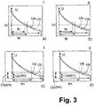
- FIGS. 3a to 3d each show measuring voltages Ua and Ub, respectively, at the coil terminals 16a, 16b during of a measuring process.
- a first measuring circuit is closed, which is connected to the measuring voltage 18 with a measuring voltage U, z. B. also Uv, via the closed first measuring switch means 17a, the first measuring resistor 15a and the first (left) armature coil 16 to ground 8 flows.
- a first RL element is formed as a series circuit of the measuring resistor 15a and the first armature coil 6a, which has a specific, dependent on the ohmic resistance and the inductance timing; With a fixed measuring resistor 15a, 15b, the time constant ta, tb thus depends on the respective inductance La, Lb.
- the inductances depend on the armature position; in the in Fig. 1 shown right armature position II, the first (left) armature coil 6 has a low inductance La than in the first armature position I.
- a meaningful comparison can not be made by measurements in the various armature positions, but in the present case also without actuation of the armature by comparing the armature currents, which with open power switches 9a and 9b through the measuring paths 14a and 14b flow.
- the measuring resistors 15a and 15b serve to tap a measuring voltage Ua and Ub, d. H. in particular the decoupling of the measuring voltage source 18.
- FIG. 1 shown right anchor position II is shown in the measurements of Figure 3b and 3d, respectively Fig. 3a, c the first (left) anchor position I:
- the closed measuring switch devices 17a and 17b are opened successively or simultaneously.
- a simultaneous opening of the measuring switch means 17a and 17b makes sense.
- a temporally non-constant current flow through both measuring paths 14a, 14b and the armature coils 6a and 6b sets in, with measuring currents I -14a through the first measuring path 14a and I -14b through the second measuring path 14b , wherein the measuring currents I -14a, I-14b lead to a voltage drop at the coil terminals 16a and 16b and thus the measuring voltages Ua and Ub are formed.
- the inductance L of the second (right) armature coil 6b is greater than the first inductance La of the first (left) armature coil 6a, so that tb ⁇ ta. This is reflected in the measurements Figure 3b and 3d , According to FIG.
- the measuring circuit after FIG. 1 corresponds, the measured voltages Ua and Ub are directly compared with each other, so that the comparator 20 is a state signal Uv or 0 volts or a logic 1 or 0 or indicates depending on which measurement voltage Ua or Ub is greater.
- the comparator 20 takes a measurement after a relevant measurement time tm at which a sufficiently significant difference is expected.
- FIG. 2 The embodiment of the FIG. 2 is opposite FIG. 1 modified to the effect that the two measuring switch devices 17a and 17b is replaced by a common measuring switch device 17. With the detection device 12 of the FIG. 2 Thus, in each case measurements can be made in which the measuring paths 14a and 14b are opened and closed simultaneously and thus the measurements take place simultaneously, as with FIG. 3 already described.
- measurements can also be carried out successively, which is possible according to Figure 1 with separate measuring switch devices 17a and 17b; In this case, then the measurement voltages Ua and Ub successively z. B. read out via the measuring port a microcontroller and subsequently compared with each other. Measurements should be taken immediately after each other so that changing conditions such as temperature etc. will not change the measurements.
- the measuring method according to FIG. 3 show measurements when switching off the measuring currents, ie when opening the measuring switch devices 17a, 17b and 17 respectively.
- Fig. 4 shows corresponding measurements when switching on the current, ie when closing the measuring switch devices 17a, 17b and 17 after Fig. 1 or Fig. 2 ,
- the measurement path shows the closed anchor side according to FIG. 1 and 2 , thus the second or right measurement path 14b, a larger time constant and thus a slower or slower rise behavior.
- both measurements after Fig. 3 and 4 be carried out one behind the other, so that first according to FIG. 1 or FIG. 2 the measuring switch means 17a and 17b and the common measuring switch means 17 is closed, and the rise of the measuring current or the voltages Ua and Ub is measured, and subsequently measurements when switching off or opening the switch means according to FIG. 3 respectively.
- Fig. 5 shows one of the Fig. 1 corresponding training, with extending in the axial direction Polan instrumentsn 2 a and 2 b for conditioning the armature. 3
- Fig. 6 shows one of the Fig. 2 corresponding embodiment with explicitly marked Polan arrangementsn 2 a, 2 b.
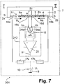
- Fig. 7 shows a further embodiment of a solenoid valve device 201, in which the detection device 212 is integrated into the power circuit:
- Shunt resistors 34a, 34b are connected between the two ground terminals 16c of the first armature coil 6a and 16d of the second armature coil 6b.
- the shunt resistors 34a and 34b are sufficiently small that the power loss in the power circuit is not relevant.
- the power currents of the two armature coils 6a and 6b also serve as measuring currents I_14a and I_14b.
- the measuring voltages Ua and Ub are thus removed in front of the shunt resistors 34a, 34b, ie between the shunt resistors 34a, 34b and the respective ground terminal 16c, 16d of the armature coils 6a and 6b and evaluated via the comparator 20 serving as comparator, corresponding to FIG above-described embodiments.
- Fig. 8 shows a further embodiment of a solenoid valve device 301, wherein the detection device 312 compared to the embodiment of Fig. 1 and Fig. 5 modified to use the supply voltage source 10;
- a common voltage source namely the supply voltage source 10
- first and second measuring resistors 15a, 15b, z. B. in the range of a few k ⁇ , provided to initiate no switching process by the measuring currents I-14a and I-14b and continue to keep the energy consumption and the loss performance occurring during measurements low.
- Fig. 1 . 2 . 5 . 6 can also be used as a measuring voltage source 18, in particular also already in the control device 22 indicated here, which serves as a control and evaluation device for evaluating and detecting the armature position I or II, advantageously also for controlling the power switches 9a and 9b for the switching operations (circuit breaker), already existing voltage sources of z. B. 5 volts over 3.3 volts are used. Thus, no additional overhead, or the formation of an additional voltage source is required to form the measuring voltage source 18.
Landscapes
- Physics & Mathematics (AREA)
- Electromagnetism (AREA)
- Engineering & Computer Science (AREA)
- Power Engineering (AREA)
- General Engineering & Computer Science (AREA)
- Manufacturing & Machinery (AREA)
- Mechanical Engineering (AREA)
- General Physics & Mathematics (AREA)
- Magnetically Actuated Valves (AREA)
Claims (18)
- Dispositif d'électrovanne (1, 101, 201, 301) bistable pour un système de fluide (30),
le dispositif d'électrovanne (1) possédant une électrovanne bistable (7) comprenant :une culasse à aimant permanent (2) ayant un premier talon polaire (2a) et un deuxième talon polaire (2b) destinés à former un premier circuit ferromagnétique et un deuxième circuit ferromagnétique,un induit (3) en matériau magnétiquement conducteur, qui peut être positionné entre une première position d'induit (I) en vue de reposer contre le premier noyau (2a) en formant un entrefer (11) par rapport au deuxième noyau (2b) et une deuxième position d'induit (II) en vue de reposer contre le deuxième noyau (2b) en formant un entrefer (11) par rapport au premier noyau (2a),une première bobine d'induit (6a) destinée à être alimentée électriquement pour un positionnement dans la première position d'induit (I) ainsi qu'une deuxième bobine d'induit (6b) destinée à être alimentée électriquement pour un positionnement dans la deuxième position d'induit (II),un étage final (9a, 9b, 10) destiné à alimenter électriquement respectivement l'une des bobines d'induit (6a, 6b) pour un positionnement de l'induit (3),caractérisé en ce quele dispositif d'électrovanne (1) possède en outre un dispositif de détection (12, 112, 212, 312) destiné à évaluer ou à mesurer une première inductance (La, Lb) de la première bobine d'induit (6a) et à évaluer ou à mesurer une deuxième inductance (La, Lb) de la deuxième bobine d'induit (6b) sans positionnement de l'induit (3) et à comparer les inductances (La, Lb) de la première bobine d'induit (6a) et de la deuxième bobine d'induit (6b) et à délivrer un signal d'état (S1) qui indique la position d'induit (I, II). - Dispositif d'électrovanne (1, 101, 201, 301) selon la revendication 1, caractérisé en ce que le dispositif de détection (12, 112, 212, 312) possède :un premier trajet de mesure (14a) raccordé à une source de tension de mesure (18) servant à alimenter électriquement la première bobine d'induit (6a) en vue d'évaluer ou de mesurer la première inductance (La),un deuxième trajet de mesure (14b) raccordé à la source de tension de mesure (18) servant à alimenter électriquement la deuxième bobine d'induit (6b) en vue d'évaluer ou de mesurer la deuxième inductance (Lb),un dispositif comparateur (20) raccordé aux trajets de mesure (14a, 14b).
- Dispositif d'électrovanne (1, 101) selon la revendication 2, caractérisé en ce que l'induit (3) peut être positionné par l'alimentation électrique des bobines d'induit (6a, 6b) par le biais d'une source de tension d'alimentation (10) et la source de tension de mesure (18) est différente de la source de tension d'alimentation (10), de préférence avec une tension de mesure plus petite que la tension d'alimentation de la source de tension d'alimentation (10).
- Dispositif d'électrovanne (1, 101) selon la revendication 3, caractérisé en ce qu'il possède un dispositif de commande (22) destiné à recevoir le signal d'état (S1) et/ou à commander un dispositif de commutation de puissance (9a, 9b) et/ou à commander un dispositif de commutation de mesure (17a, 17b, 17), et la source de tension de mesure (18) est également conçue pour l'alimentation électrique du dispositif de commande (22).
- Dispositif d'électrovanne (1, 101) selon l'une des revendications 2 à 4, caractérisé en ce que le premier trajet de mesure (14a) possède une première résistance de mesure (15a) destinée à former un circuit série de la première bobine d'induit (6a) avec la première résistance de mesure (15a) à la source de tension de mesure (18) en tant que premier circuit diviseur de tension, et
le deuxième trajet de mesure (14b) possède une deuxième résistance de mesure (15b) destinée à former un circuit série de la deuxième bobine d'induit (6b) avec la deuxième résistance de mesure (15b) à la source de tension de mesure (18) en tant que deuxième circuit diviseur de tension,
la première et la deuxième résistance de mesure (15a, 15b) étant de la même valeur,
le dispositif comparateur (20) comparant une amplitude et/ou un comportement dans le temps d'une première tension de mesure (Ua) entre la première résistance de mesure (15a) et la première bobine d'induit (6a) et d'une deuxième tension de mesure (Ub) entre la deuxième résistance de mesure (15b) et la deuxième bobine d'induit (6b). - Dispositif d'électrovanne (1, 101) selon l'une des revendications 2 à 5, caractérisé en ce qu'au moins un dispositif de commutation de mesure (17a, 17b, 17) est présent, servant à fermer les circuits de courant de mesure par le biais des trajets de mesure (14a, 14b) et des bobines d'induit (6a, 6b), le dispositif de commutation de mesure (17a, 17b, 17) étant différent d'un dispositif de commutation de puissance (9a, 9b) destiné à alimenter électriquement les bobines d'induit (6a, 6b) pour le positionnement de l'induit (3).
- Dispositif d'électrovanne (1) selon la revendication 6, caractérisé en ce que des dispositifs de commutation de mesure (17a, 17b) séparés destinés à alimenter électriquement simultanément ou successivement les trajets de mesure (14a, 14b) se trouvent dans le premier trajet de mesure (14a) et le deuxième trajet de mesure (14b).
- Dispositif d'électrovanne (101) selon la revendication 6, caractérisé en ce qu'un dispositif de commutation de mesure (17) commun est présent pour les deux trajets de mesure (14a, 14b).
- Dispositif d'électrovanne (301) selon l'une des revendications 2 ou 5 à 7, caractérisé en ce que l'induit (3) peut être positionné par l'alimentation électrique des bobines d'induit (6a, 6b) par le biais d'une source de tension d'alimentation (10) et de commutateurs de puissance (17a, 17b),
les trajets de mesure (14a, 14b) étant raccordés à la source de tension d'alimentation (10) respectivement par un commutateur de mesure (17a, 17b) et une résistance de mesure (15a, 15b) en parallèle avec les commutateurs de puissance (9a, 9b), et
le dispositif comparateur (20) relevant et comparant entre elles les tensions de mesure (Ua, Ub) qui chutent aux bornes des résistances de mesure (15a, 15b). - Dispositif d'électrovanne (201) selon l'une des revendications 1 à 9, caractérisé en ce que l'induit (3) peut être positionné par l'alimentation électrique des bobines d'induit (6a, 6b) par le biais d'une source de tension d'alimentation (10) et de commutateurs de puissance (17a, 17b),
le dispositif de détection (212) possède une première et une deuxième résistance shunt (34a, 34b) et un dispositif comparateur (20),
une résistance shunt (34a, 34b) étant respectivement branchée en série avec une bobine d'induit (6a, 6b) et un commutateur de puissance (17a, 17b) à la source de tension d'alimentation (10), et
le dispositif comparateur (20) relevant et comparant entre elles les tensions de mesure (Ua, Ub) qui chutent aux bornes des résistances shunt (34a, 34b), notamment par rapport à la masse (8). - Dispositif d'électrovanne (1, 101, 201, 301) selon l'une des revendications 4 à 10, caractérisé en ce que le dispositif comparateur (20) compare l'amplitude des deux tensions de mesure (Ua, Ub) respectivement après un temps de mesure (tm) prédéfini lors d'une opération de mise en circuit et/ou de mise hors circuit et délivre le signal d'état (S1) en fonction d'une différence entre les deux tensions de mesure (Ua, Ub), par exemple en tant qu'amplificateur opérationnel (20) ou microcontrôleur.
- Dispositif d'électrovanne (1, 101, 201, 301) selon l'une des revendications 4 à 11, caractérisé en ce que le dispositif comparateur (20) compare une durée (ta, Tb) des deux tensions de mesure (Ua, Ub) jusqu'à atteindre une tension de référence (Ur) lors d'une opération de mise en circuit et/ou de mise hors circuit.
- Dispositif d'électrovanne (1, 101, 201, 301) selon l'une des revendications 4 à 12, caractérisé en ce que le dispositif comparateur (20) est configuré pour relever simultanément les deux tensions de mesure (Ua, Ub), par exemple en tant qu'amplificateur opérationnel, ou pour relever successivement les deux tensions de mesure (Ua, Ub), par exemple en tant que microcontrôleur.
- Dispositif d'électrovanne (1, 101, 201, 301) selon l'une des revendications précédentes, caractérisé en ce qu'il est configuré de manière symétrique dans les propriétés magnétiques et électriques du dispositif à aimant permanent (2), de l'induit (3) avec ses bobines d'induit (6a, 6b) et des trajets de mesure (14a, 14b).
- Frein de stationnement électropneumatique, qui possède un dispositif d'électrovanne (1, 101) selon l'une des revendications précédentes, une position d'induit (I, II) correspondant à un frein de stationnement desserré et l'autre position d'induit (II, I) à un frein de stationnement serré.
- Procédé pour déterminer une position d'induit (I, II) d'une électrovanne bistable (7) présente dans un système de fluide (30), laquelle possède un dispositif à aimant permanent (2) ayant un premier noyau (2a) et un deuxième noyau (2b), un induit (3) qui peut être positionné entre une première position d'induit (I) en vue de reposer contre le premier noyau (2a), une deuxième position d'induit (II) en vue de reposer contre le deuxième noyau (2b) et deux bobines d'induit (6a, 6b) destinées au positionnement de l'induit (3) entre les positions d'induit (I, II),
dans une opération de mesure sans positionnement de l'induit (3), un premier courant de mesure (I-14a) étant conduit d'une source de tension de mesure (18) par le biais d'un premier trajet de mesure (14a) et d'une première bobine d'induit (6a),
moyennant quoi une première tension de mesure (Ua) dépendant de la première inductance (La) de la première bobine d'induit (6a) est formée, et un deuxième courant de mesure (I-14b) étant conduit de la source de tension de mesure (18) par le biais d'un deuxième trajet de mesure (14b) et d'une deuxième bobine d'induit (6a), moyennant quoi une deuxième tension de mesure (Ub) dépendant de la deuxième inductance (Lb) de la deuxième bobine d'induit (6b) est formée, et
une amplitude et/ou un comportement dans le temps de la première tension de mesure (Ua) et de la deuxième tension de mesure (Ub) étant comparés entre eux et un signal d'état (S1) étant délivré en fonction de la comparaison. - Procédé selon la revendication 16, caractérisé en ce que les tensions de mesure (Ua, Ub) sont générées simultanément et sont comparées entre elles par un dispositif comparateur (20) après une durée prédéfinie, notamment lors d'une opération de mise en circuit et/ou de mise hors circuit, par exemple par calcul de la différence.
- Procédé selon la revendication 17, caractérisé en ce que les durées des tensions de mesure (Ua, Ub) jusqu'à atteindre une valeur de tension prédéfinie sont comparées entre elles.
Applications Claiming Priority (2)
| Application Number | Priority Date | Filing Date | Title |
|---|---|---|---|
| DE102016002677.4A DE102016002677A1 (de) | 2016-03-05 | 2016-03-05 | Bistabile Magnetventil-Einrichtung und Verfahren zum Ermitteln einer Ankerstellung eines bistabilen Magnetventils |
| PCT/EP2017/000135 WO2017153030A1 (fr) | 2016-03-05 | 2017-02-02 | Moyen formant vanne magnétique bistable et procédé de détermination de la position de l'induit d'une vanne magnétique bistable |
Publications (2)
| Publication Number | Publication Date |
|---|---|
| EP3424058A1 EP3424058A1 (fr) | 2019-01-09 |
| EP3424058B1 true EP3424058B1 (fr) | 2019-10-23 |
Family
ID=57965886
Family Applications (1)
| Application Number | Title | Priority Date | Filing Date |
|---|---|---|---|
| EP17703319.8A Active EP3424058B1 (fr) | 2016-03-05 | 2017-02-02 | Moyen formant vanne magnétique bistable et procédé de détermination de la position de l'induit d'une vanne magnétique bistable |
Country Status (5)
| Country | Link |
|---|---|
| US (1) | US10699835B2 (fr) |
| EP (1) | EP3424058B1 (fr) |
| CN (1) | CN108475572B (fr) |
| DE (1) | DE102016002677A1 (fr) |
| WO (1) | WO2017153030A1 (fr) |
Families Citing this family (3)
| Publication number | Priority date | Publication date | Assignee | Title |
|---|---|---|---|---|
| DE202018101968U1 (de) * | 2018-04-11 | 2019-07-12 | Woco Industrietechnik Gmbh | Elektromagnetisches Ventil und Schubumluftventil |
| EP4386176A1 (fr) * | 2019-02-19 | 2024-06-19 | Probe Technology Services, Inc. | Nouveau capteur de position de noyau |
| WO2022084374A1 (fr) * | 2020-10-22 | 2022-04-28 | Behr-Hella Thermocontrol Gmbh | Procédé et dispositif de commande d'un solénoïde de type à traction |
Family Cites Families (5)
| Publication number | Priority date | Publication date | Assignee | Title |
|---|---|---|---|---|
| DE3730381C2 (de) | 1987-09-10 | 1997-06-12 | Kuhnke Gmbh Kg H | Bistabiles Magnetventil mit dauermagnetischer Haltekraft |
| DE102005018012A1 (de) * | 2005-04-18 | 2006-10-19 | Zf Friedrichshafen Ag | Sensorlose Positionserkennung in einem elektromagnetischen Aktuator |
| DE102005041873A1 (de) * | 2005-08-23 | 2007-03-08 | Linde Ag | Verfahren zur Bestimmung der Position eines Ankers eines Elektromagneten |
| DE102007016787A1 (de) * | 2007-04-05 | 2008-10-09 | Schultz, Wolfgang E., Dipl.-Ing. | Verfahren zur Bestimmung der Ankerlage in einem Elektromagneten |
| DE102011081921A1 (de) * | 2011-08-31 | 2013-02-28 | Siemens Aktiengesellschaft | Magnetaktor und Verfahren zu dessen Einsatz an elektrischen Schaltanlagen |
-
2016
- 2016-03-05 DE DE102016002677.4A patent/DE102016002677A1/de not_active Withdrawn
-
2017
- 2017-02-02 WO PCT/EP2017/000135 patent/WO2017153030A1/fr unknown
- 2017-02-02 CN CN201780007325.4A patent/CN108475572B/zh active Active
- 2017-02-02 US US16/081,438 patent/US10699835B2/en active Active
- 2017-02-02 EP EP17703319.8A patent/EP3424058B1/fr active Active
Non-Patent Citations (1)
| Title |
|---|
| None * |
Also Published As
| Publication number | Publication date |
|---|---|
| US10699835B2 (en) | 2020-06-30 |
| US20190348206A1 (en) | 2019-11-14 |
| EP3424058A1 (fr) | 2019-01-09 |
| CN108475572A (zh) | 2018-08-31 |
| WO2017153030A1 (fr) | 2017-09-14 |
| DE102016002677A1 (de) | 2017-09-07 |
| CN108475572B (zh) | 2020-11-27 |
| WO2017153030A8 (fr) | 2018-04-19 |
Similar Documents
| Publication | Publication Date | Title |
|---|---|---|
| DE19806821C2 (de) | Störungsfeststellungseinrichtung zur Feststellung einer Störung in einem Magnetventil | |
| EP3424058B1 (fr) | Moyen formant vanne magnétique bistable et procédé de détermination de la position de l'induit d'une vanne magnétique bistable | |
| WO1989002648A1 (fr) | Procede et dispositif de detection des temps de commutation d'electro-vannes | |
| DE102011075935A1 (de) | Ermittlung von Funktionszuständen eines elektromagnetischen Aktors | |
| EP3053176B1 (fr) | Procédé et dispositif de surveillance d'au moins un contact de commande pour un véhicule | |
| DE102015209195A1 (de) | Einrastventilanordnung mit Positionserkennung | |
| EP1762852B1 (fr) | Dispositif et procédé pour mesurer un courant passant dans un conducteur électrique | |
| EP3642473B1 (fr) | Dispositif de détection de l'état d'un injecteur | |
| DE2338859C3 (de) | Prüfschaltung für ein Antiblockier-Regelsystem | |
| EP3580769B1 (fr) | Dispositif à électrovanne bistable et procédé de surveillance de celui-ci | |
| EP3257060B1 (fr) | Électrovanne, dispositif de vanne avec une électrovanne de ce genre, véhicule avec ledit dispositif et procédé de fonctionnement d'une électrovanne de ce genre | |
| DE102016221695B4 (de) | Steuereinrichtung für ein Kraftfahrzeug, Kraftfahrzeug und Gespann | |
| DE19611522B4 (de) | Verfahren und Vorrichtung zur Fehlererkennung bei einer Endstufenschaltungsanordnung | |
| DE102011077363A1 (de) | Elektrische Vorrichtung und Verfahren zur Diagnose eines Schützes | |
| DE10118191C1 (de) | Verfahren zum Erkennen eines Schaltzustands eines Schalters | |
| WO1997000525A1 (fr) | Circuit pour le fonctionnement d'un electroaimant | |
| EP1981747A1 (fr) | Procédé pour commander une électrovanne | |
| DE10037495B4 (de) | Verfahren und Vorrichtung zum Erkennen einer Fehlfunktion eines Sensors oder eines Leitungsbruchs | |
| DE102013222405A1 (de) | Vorrichtung zum Überwachen eines Betriebs eines induktiven Elements | |
| DE102019132769A1 (de) | Verfahren und Schaltungsanordnung zur Diagnose eines Schützes einer elektrischen Vorrichtung | |
| DE102012204321A1 (de) | Elektromagnetische Stellvorrichtung mit Eignung zur Ankerpositionserfassung | |
| WO2020114822A1 (fr) | Dispositif électromagnétique pour système de freinage de véhicule, procédé et unité de commande pour faire fonctionner un dispositif électromagnétique pour système de freinage de véhicule et système de freinage de véhicule | |
| DE102015015461B4 (de) | Vorrichtung und Verfahren zum Schalten eines Stromes in einer elektrischen Versorgungsleitung sowie Kraftfahrzeug | |
| DE10260723B4 (de) | Verfahren und Vorrichtung zur Testansteuerung | |
| DE10246107B4 (de) | Verfahren sowie Schaltungsanordnung zur Fehlerüberwachung wenigstens eines elektrischen Verbrauchers |
Legal Events
| Date | Code | Title | Description |
|---|---|---|---|
| STAA | Information on the status of an ep patent application or granted ep patent |
Free format text: STATUS: UNKNOWN |
|
| STAA | Information on the status of an ep patent application or granted ep patent |
Free format text: STATUS: THE INTERNATIONAL PUBLICATION HAS BEEN MADE |
|
| PUAI | Public reference made under article 153(3) epc to a published international application that has entered the european phase |
Free format text: ORIGINAL CODE: 0009012 |
|
| STAA | Information on the status of an ep patent application or granted ep patent |
Free format text: STATUS: REQUEST FOR EXAMINATION WAS MADE |
|
| 17P | Request for examination filed |
Effective date: 20181005 |
|
| AK | Designated contracting states |
Kind code of ref document: A1 Designated state(s): AL AT BE BG CH CY CZ DE DK EE ES FI FR GB GR HR HU IE IS IT LI LT LU LV MC MK MT NL NO PL PT RO RS SE SI SK SM TR |
|
| AX | Request for extension of the european patent |
Extension state: BA ME |
|
| DAV | Request for validation of the european patent (deleted) | ||
| DAX | Request for extension of the european patent (deleted) | ||
| GRAP | Despatch of communication of intention to grant a patent |
Free format text: ORIGINAL CODE: EPIDOSNIGR1 |
|
| STAA | Information on the status of an ep patent application or granted ep patent |
Free format text: STATUS: GRANT OF PATENT IS INTENDED |
|
| GRAS | Grant fee paid |
Free format text: ORIGINAL CODE: EPIDOSNIGR3 |
|
| INTG | Intention to grant announced |
Effective date: 20190820 |
|
| GRAA | (expected) grant |
Free format text: ORIGINAL CODE: 0009210 |
|
| STAA | Information on the status of an ep patent application or granted ep patent |
Free format text: STATUS: THE PATENT HAS BEEN GRANTED |
|
| AK | Designated contracting states |
Kind code of ref document: B1 Designated state(s): AL AT BE BG CH CY CZ DE DK EE ES FI FR GB GR HR HU IE IS IT LI LT LU LV MC MK MT NL NO PL PT RO RS SE SI SK SM TR |
|
| REG | Reference to a national code |
Ref country code: GB Ref legal event code: FG4D Free format text: NOT ENGLISH |
|
| REG | Reference to a national code |
Ref country code: CH Ref legal event code: EP |
|
| REG | Reference to a national code |
Ref country code: IE Ref legal event code: FG4D Free format text: LANGUAGE OF EP DOCUMENT: GERMAN |
|
| REG | Reference to a national code |
Ref country code: DE Ref legal event code: R096 Ref document number: 502017002655 Country of ref document: DE |
|
| REG | Reference to a national code |
Ref country code: AT Ref legal event code: REF Ref document number: 1194605 Country of ref document: AT Kind code of ref document: T Effective date: 20191115 |
|
| REG | Reference to a national code |
Ref country code: NL Ref legal event code: MP Effective date: 20191023 |
|
| REG | Reference to a national code |
Ref country code: LT Ref legal event code: MG4D |
|
| PG25 | Lapsed in a contracting state [announced via postgrant information from national office to epo] |
Ref country code: PT Free format text: LAPSE BECAUSE OF FAILURE TO SUBMIT A TRANSLATION OF THE DESCRIPTION OR TO PAY THE FEE WITHIN THE PRESCRIBED TIME-LIMIT Effective date: 20200224 Ref country code: FI Free format text: LAPSE BECAUSE OF FAILURE TO SUBMIT A TRANSLATION OF THE DESCRIPTION OR TO PAY THE FEE WITHIN THE PRESCRIBED TIME-LIMIT Effective date: 20191023 Ref country code: BG Free format text: LAPSE BECAUSE OF FAILURE TO SUBMIT A TRANSLATION OF THE DESCRIPTION OR TO PAY THE FEE WITHIN THE PRESCRIBED TIME-LIMIT Effective date: 20200123 Ref country code: LT Free format text: LAPSE BECAUSE OF FAILURE TO SUBMIT A TRANSLATION OF THE DESCRIPTION OR TO PAY THE FEE WITHIN THE PRESCRIBED TIME-LIMIT Effective date: 20191023 Ref country code: NL Free format text: LAPSE BECAUSE OF FAILURE TO SUBMIT A TRANSLATION OF THE DESCRIPTION OR TO PAY THE FEE WITHIN THE PRESCRIBED TIME-LIMIT Effective date: 20191023 Ref country code: GR Free format text: LAPSE BECAUSE OF FAILURE TO SUBMIT A TRANSLATION OF THE DESCRIPTION OR TO PAY THE FEE WITHIN THE PRESCRIBED TIME-LIMIT Effective date: 20200124 Ref country code: NO Free format text: LAPSE BECAUSE OF FAILURE TO SUBMIT A TRANSLATION OF THE DESCRIPTION OR TO PAY THE FEE WITHIN THE PRESCRIBED TIME-LIMIT Effective date: 20200123 Ref country code: PL Free format text: LAPSE BECAUSE OF FAILURE TO SUBMIT A TRANSLATION OF THE DESCRIPTION OR TO PAY THE FEE WITHIN THE PRESCRIBED TIME-LIMIT Effective date: 20191023 Ref country code: SE Free format text: LAPSE BECAUSE OF FAILURE TO SUBMIT A TRANSLATION OF THE DESCRIPTION OR TO PAY THE FEE WITHIN THE PRESCRIBED TIME-LIMIT Effective date: 20191023 Ref country code: LV Free format text: LAPSE BECAUSE OF FAILURE TO SUBMIT A TRANSLATION OF THE DESCRIPTION OR TO PAY THE FEE WITHIN THE PRESCRIBED TIME-LIMIT Effective date: 20191023 |
|
| PG25 | Lapsed in a contracting state [announced via postgrant information from national office to epo] |
Ref country code: RS Free format text: LAPSE BECAUSE OF FAILURE TO SUBMIT A TRANSLATION OF THE DESCRIPTION OR TO PAY THE FEE WITHIN THE PRESCRIBED TIME-LIMIT Effective date: 20191023 Ref country code: IS Free format text: LAPSE BECAUSE OF FAILURE TO SUBMIT A TRANSLATION OF THE DESCRIPTION OR TO PAY THE FEE WITHIN THE PRESCRIBED TIME-LIMIT Effective date: 20200224 Ref country code: HR Free format text: LAPSE BECAUSE OF FAILURE TO SUBMIT A TRANSLATION OF THE DESCRIPTION OR TO PAY THE FEE WITHIN THE PRESCRIBED TIME-LIMIT Effective date: 20191023 |
|
| PG25 | Lapsed in a contracting state [announced via postgrant information from national office to epo] |
Ref country code: AL Free format text: LAPSE BECAUSE OF FAILURE TO SUBMIT A TRANSLATION OF THE DESCRIPTION OR TO PAY THE FEE WITHIN THE PRESCRIBED TIME-LIMIT Effective date: 20191023 |
|
| REG | Reference to a national code |
Ref country code: DE Ref legal event code: R097 Ref document number: 502017002655 Country of ref document: DE |
|
| PG2D | Information on lapse in contracting state deleted |
Ref country code: IS |
|
| PG25 | Lapsed in a contracting state [announced via postgrant information from national office to epo] |
Ref country code: DK Free format text: LAPSE BECAUSE OF FAILURE TO SUBMIT A TRANSLATION OF THE DESCRIPTION OR TO PAY THE FEE WITHIN THE PRESCRIBED TIME-LIMIT Effective date: 20191023 Ref country code: ES Free format text: LAPSE BECAUSE OF FAILURE TO SUBMIT A TRANSLATION OF THE DESCRIPTION OR TO PAY THE FEE WITHIN THE PRESCRIBED TIME-LIMIT Effective date: 20191023 Ref country code: RO Free format text: LAPSE BECAUSE OF FAILURE TO SUBMIT A TRANSLATION OF THE DESCRIPTION OR TO PAY THE FEE WITHIN THE PRESCRIBED TIME-LIMIT Effective date: 20191023 Ref country code: CZ Free format text: LAPSE BECAUSE OF FAILURE TO SUBMIT A TRANSLATION OF THE DESCRIPTION OR TO PAY THE FEE WITHIN THE PRESCRIBED TIME-LIMIT Effective date: 20191023 Ref country code: EE Free format text: LAPSE BECAUSE OF FAILURE TO SUBMIT A TRANSLATION OF THE DESCRIPTION OR TO PAY THE FEE WITHIN THE PRESCRIBED TIME-LIMIT Effective date: 20191023 Ref country code: IS Free format text: LAPSE BECAUSE OF FAILURE TO SUBMIT A TRANSLATION OF THE DESCRIPTION OR TO PAY THE FEE WITHIN THE PRESCRIBED TIME-LIMIT Effective date: 20200223 |
|
| PLBE | No opposition filed within time limit |
Free format text: ORIGINAL CODE: 0009261 |
|
| STAA | Information on the status of an ep patent application or granted ep patent |
Free format text: STATUS: NO OPPOSITION FILED WITHIN TIME LIMIT |
|
| PG25 | Lapsed in a contracting state [announced via postgrant information from national office to epo] |
Ref country code: SK Free format text: LAPSE BECAUSE OF FAILURE TO SUBMIT A TRANSLATION OF THE DESCRIPTION OR TO PAY THE FEE WITHIN THE PRESCRIBED TIME-LIMIT Effective date: 20191023 Ref country code: IT Free format text: LAPSE BECAUSE OF FAILURE TO SUBMIT A TRANSLATION OF THE DESCRIPTION OR TO PAY THE FEE WITHIN THE PRESCRIBED TIME-LIMIT Effective date: 20191023 Ref country code: SM Free format text: LAPSE BECAUSE OF FAILURE TO SUBMIT A TRANSLATION OF THE DESCRIPTION OR TO PAY THE FEE WITHIN THE PRESCRIBED TIME-LIMIT Effective date: 20191023 |
|
| 26N | No opposition filed |
Effective date: 20200724 |
|
| REG | Reference to a national code |
Ref country code: CH Ref legal event code: PL |
|
| REG | Reference to a national code |
Ref country code: BE Ref legal event code: MM Effective date: 20200229 |
|
| PG25 | Lapsed in a contracting state [announced via postgrant information from national office to epo] |
Ref country code: LU Free format text: LAPSE BECAUSE OF NON-PAYMENT OF DUE FEES Effective date: 20200202 Ref country code: MC Free format text: LAPSE BECAUSE OF FAILURE TO SUBMIT A TRANSLATION OF THE DESCRIPTION OR TO PAY THE FEE WITHIN THE PRESCRIBED TIME-LIMIT Effective date: 20191023 |
|
| PG25 | Lapsed in a contracting state [announced via postgrant information from national office to epo] |
Ref country code: SI Free format text: LAPSE BECAUSE OF FAILURE TO SUBMIT A TRANSLATION OF THE DESCRIPTION OR TO PAY THE FEE WITHIN THE PRESCRIBED TIME-LIMIT Effective date: 20191023 Ref country code: LI Free format text: LAPSE BECAUSE OF NON-PAYMENT OF DUE FEES Effective date: 20200229 Ref country code: CH Free format text: LAPSE BECAUSE OF NON-PAYMENT OF DUE FEES Effective date: 20200229 |
|
| PG25 | Lapsed in a contracting state [announced via postgrant information from national office to epo] |
Ref country code: IE Free format text: LAPSE BECAUSE OF NON-PAYMENT OF DUE FEES Effective date: 20200202 |
|
| PG25 | Lapsed in a contracting state [announced via postgrant information from national office to epo] |
Ref country code: BE Free format text: LAPSE BECAUSE OF NON-PAYMENT OF DUE FEES Effective date: 20200229 |
|
| REG | Reference to a national code |
Ref country code: DE Ref legal event code: R081 Ref document number: 502017002655 Country of ref document: DE Owner name: ZF CV SYSTEMS EUROPE BV, BE Free format text: FORMER OWNER: WABCO EUROPE BVBA, BRUESSEL, BE |
|
| PG25 | Lapsed in a contracting state [announced via postgrant information from national office to epo] |
Ref country code: TR Free format text: LAPSE BECAUSE OF FAILURE TO SUBMIT A TRANSLATION OF THE DESCRIPTION OR TO PAY THE FEE WITHIN THE PRESCRIBED TIME-LIMIT Effective date: 20191023 Ref country code: MT Free format text: LAPSE BECAUSE OF FAILURE TO SUBMIT A TRANSLATION OF THE DESCRIPTION OR TO PAY THE FEE WITHIN THE PRESCRIBED TIME-LIMIT Effective date: 20191023 Ref country code: CY Free format text: LAPSE BECAUSE OF FAILURE TO SUBMIT A TRANSLATION OF THE DESCRIPTION OR TO PAY THE FEE WITHIN THE PRESCRIBED TIME-LIMIT Effective date: 20191023 |
|
| PG25 | Lapsed in a contracting state [announced via postgrant information from national office to epo] |
Ref country code: MK Free format text: LAPSE BECAUSE OF FAILURE TO SUBMIT A TRANSLATION OF THE DESCRIPTION OR TO PAY THE FEE WITHIN THE PRESCRIBED TIME-LIMIT Effective date: 20191023 |
|
| REG | Reference to a national code |
Ref country code: AT Ref legal event code: MM01 Ref document number: 1194605 Country of ref document: AT Kind code of ref document: T Effective date: 20220202 |
|
| PG25 | Lapsed in a contracting state [announced via postgrant information from national office to epo] |
Ref country code: AT Free format text: LAPSE BECAUSE OF NON-PAYMENT OF DUE FEES Effective date: 20220202 |
|
| P01 | Opt-out of the competence of the unified patent court (upc) registered |
Effective date: 20230528 |
|
| PGFP | Annual fee paid to national office [announced via postgrant information from national office to epo] |
Ref country code: GB Payment date: 20231214 Year of fee payment: 8 |
|
| PGFP | Annual fee paid to national office [announced via postgrant information from national office to epo] |
Ref country code: FR Payment date: 20231212 Year of fee payment: 8 |
|
| PGFP | Annual fee paid to national office [announced via postgrant information from national office to epo] |
Ref country code: DE Payment date: 20231205 Year of fee payment: 8 |