EP3423717B1 - Elektromagnetisch betätigbares einlassventil und hochdruckpumpe mit einlassventil - Google Patents
Elektromagnetisch betätigbares einlassventil und hochdruckpumpe mit einlassventil Download PDFInfo
- Publication number
- EP3423717B1 EP3423717B1 EP17700485.0A EP17700485A EP3423717B1 EP 3423717 B1 EP3423717 B1 EP 3423717B1 EP 17700485 A EP17700485 A EP 17700485A EP 3423717 B1 EP3423717 B1 EP 3423717B1
- Authority
- EP
- European Patent Office
- Prior art keywords
- magnet
- inlet valve
- magnet armature
- intermediate element
- pump
- Prior art date
- Legal status (The legal status is an assumption and is not a legal conclusion. Google has not performed a legal analysis and makes no representation as to the accuracy of the status listed.)
- Active
Links
Images


Classifications
-
- F—MECHANICAL ENGINEERING; LIGHTING; HEATING; WEAPONS; BLASTING
- F02—COMBUSTION ENGINES; HOT-GAS OR COMBUSTION-PRODUCT ENGINE PLANTS
- F02M—SUPPLYING COMBUSTION ENGINES IN GENERAL WITH COMBUSTIBLE MIXTURES OR CONSTITUENTS THEREOF
- F02M59/00—Pumps specially adapted for fuel-injection and not provided for in groups F02M39/00 -F02M57/00, e.g. rotary cylinder-block type of pumps
- F02M59/20—Varying fuel delivery in quantity or timing
- F02M59/36—Varying fuel delivery in quantity or timing by variably-timed valves controlling fuel passages to pumping elements or overflow passages
- F02M59/366—Valves being actuated electrically
-
- F—MECHANICAL ENGINEERING; LIGHTING; HEATING; WEAPONS; BLASTING
- F02—COMBUSTION ENGINES; HOT-GAS OR COMBUSTION-PRODUCT ENGINE PLANTS
- F02M—SUPPLYING COMBUSTION ENGINES IN GENERAL WITH COMBUSTIBLE MIXTURES OR CONSTITUENTS THEREOF
- F02M59/00—Pumps specially adapted for fuel-injection and not provided for in groups F02M39/00 -F02M57/00, e.g. rotary cylinder-block type of pumps
- F02M59/44—Details, components parts, or accessories not provided for in, or of interest apart from, the apparatus of groups F02M59/02 - F02M59/42; Pumps having transducers, e.g. to measure displacement of pump rack or piston
- F02M59/46—Valves
- F02M59/466—Electrically operated valves, e.g. using electromagnetic or piezoelectric operating means
-
- F—MECHANICAL ENGINEERING; LIGHTING; HEATING; WEAPONS; BLASTING
- F02—COMBUSTION ENGINES; HOT-GAS OR COMBUSTION-PRODUCT ENGINE PLANTS
- F02M—SUPPLYING COMBUSTION ENGINES IN GENERAL WITH COMBUSTIBLE MIXTURES OR CONSTITUENTS THEREOF
- F02M63/00—Other fuel-injection apparatus having pertinent characteristics not provided for in groups F02M39/00 - F02M57/00 or F02M67/00; Details, component parts, or accessories of fuel-injection apparatus, not provided for in, or of interest apart from, the apparatus of groups F02M39/00 - F02M61/00 or F02M67/00; Combination of fuel pump with other devices, e.g. lubricating oil pump
- F02M63/0012—Valves
- F02M63/007—Details not provided for in, or of interest apart from, the apparatus of the groups F02M63/0014 - F02M63/0059
- F02M63/0075—Stop members in valves, e.g. plates or disks limiting the movement of armature, valve or spring
-
- F—MECHANICAL ENGINEERING; LIGHTING; HEATING; WEAPONS; BLASTING
- F04—POSITIVE - DISPLACEMENT MACHINES FOR LIQUIDS; PUMPS FOR LIQUIDS OR ELASTIC FLUIDS
- F04B—POSITIVE-DISPLACEMENT MACHINES FOR LIQUIDS; PUMPS
- F04B49/00—Control, e.g. of pump delivery, or pump pressure of, or safety measures for, machines, pumps, or pumping installations, not otherwise provided for, or of interest apart from, groups F04B1/00 - F04B47/00
- F04B49/22—Control, e.g. of pump delivery, or pump pressure of, or safety measures for, machines, pumps, or pumping installations, not otherwise provided for, or of interest apart from, groups F04B1/00 - F04B47/00 by means of valves
- F04B49/24—Bypassing
- F04B49/243—Bypassing by keeping open the inlet valve
-
- F—MECHANICAL ENGINEERING; LIGHTING; HEATING; WEAPONS; BLASTING
- F04—POSITIVE - DISPLACEMENT MACHINES FOR LIQUIDS; PUMPS FOR LIQUIDS OR ELASTIC FLUIDS
- F04B—POSITIVE-DISPLACEMENT MACHINES FOR LIQUIDS; PUMPS
- F04B7/00—Piston machines or pumps characterised by having positively-driven valving
- F04B7/0076—Piston machines or pumps characterised by having positively-driven valving the members being actuated by electro-magnetic means
-
- F—MECHANICAL ENGINEERING; LIGHTING; HEATING; WEAPONS; BLASTING
- F02—COMBUSTION ENGINES; HOT-GAS OR COMBUSTION-PRODUCT ENGINE PLANTS
- F02M—SUPPLYING COMBUSTION ENGINES IN GENERAL WITH COMBUSTIBLE MIXTURES OR CONSTITUENTS THEREOF
- F02M2200/00—Details of fuel-injection apparatus, not otherwise provided for
- F02M2200/02—Fuel-injection apparatus having means for reducing wear
-
- F—MECHANICAL ENGINEERING; LIGHTING; HEATING; WEAPONS; BLASTING
- F02—COMBUSTION ENGINES; HOT-GAS OR COMBUSTION-PRODUCT ENGINE PLANTS
- F02M—SUPPLYING COMBUSTION ENGINES IN GENERAL WITH COMBUSTIBLE MIXTURES OR CONSTITUENTS THEREOF
- F02M2200/00—Details of fuel-injection apparatus, not otherwise provided for
- F02M2200/80—Fuel injection apparatus manufacture, repair or assembly
- F02M2200/8084—Fuel injection apparatus manufacture, repair or assembly involving welding or soldering
-
- F—MECHANICAL ENGINEERING; LIGHTING; HEATING; WEAPONS; BLASTING
- F02—COMBUSTION ENGINES; HOT-GAS OR COMBUSTION-PRODUCT ENGINE PLANTS
- F02M—SUPPLYING COMBUSTION ENGINES IN GENERAL WITH COMBUSTIBLE MIXTURES OR CONSTITUENTS THEREOF
- F02M2200/00—Details of fuel-injection apparatus, not otherwise provided for
- F02M2200/90—Selection of particular materials
- F02M2200/9053—Metals
- F02M2200/9069—Non-magnetic metals
-
- H—ELECTRICITY
- H01—ELECTRIC ELEMENTS
- H01F—MAGNETS; INDUCTANCES; TRANSFORMERS; SELECTION OF MATERIALS FOR THEIR MAGNETIC PROPERTIES
- H01F7/00—Magnets
- H01F7/06—Electromagnets; Actuators including electromagnets
- H01F7/08—Electromagnets; Actuators including electromagnets with armatures
- H01F7/16—Rectilinearly-movable armatures
- H01F2007/1661—Electromagnets or actuators with anti-stick disc
Definitions
- the invention relates to an electromagnetically actuated inlet valve for a high-pressure pump, in particular a fuel injection system, according to the preamble of claim 1. Furthermore, the invention relates to a high-pressure pump with such an inlet valve.
- An electromagnetically actuated inlet valve for a high-pressure pump of a fuel injection system is by JP 2004 014700 A known.
- the high-pressure pump has at least one pump element with a pump piston which is driven in a lifting movement and delimits a pump working space.
- the pump work space can be connected to an inlet for the fuel via the inlet valve.
- the inlet valve comprises a valve member which interacts with a valve seat for control and which is movable between an open position and a closed position. In its closed position, the valve member comes to rest on the valve seat.
- the inlet valve comprises an electromagnetic actuator, through which the valve member can be moved.
- the electromagnetic actuator has a magnet armature which acts at least indirectly on the valve member, a magnet coil surrounding the magnet armature and a magnet core.
- the magnet armature is guided displaceably in a carrier element, the carrier element and the magnetic core being connected to one another via a sleeve-shaped component.
- the solenoid When the solenoid is energized, the magnet armature can be moved against the force of a return spring and comes into contact with the magnet core via a disc-shaped intermediate element.
- the intermediate element also serves to seal a space in which the magnetic coil is arranged. The intermediate element prevents so-called magnetic sticking, which would make it difficult to move the armature away from the magnetic core.
- the assembly of the intermediate element is complex because it is designed as a separate component and can be welded to the magnetic core.
- the inlet valve according to the invention with the features of claim 1 has the advantage that the assembly of the intermediate element is simplified in that it is welded to the sleeve-shaped component or is formed in one piece or forms the sleeve-shaped component via a collar arranged on its radially outer edge region.
- the intermediate element therefore does not have to be installed as a separate component.
- Figure 1 2 shows a schematic longitudinal section through a high pressure pump
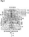
- Figure 2 in an enlarged view Figure 1 II marked section with an inlet valve of the high pressure pump
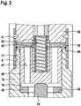
- Figure 3 one in Figure 2 with III designated section in a further enlarged representation according to a first embodiment
- Figure 4 the section III according to a second embodiment.
- a high-pressure pump is shown in sections, which is provided for fuel delivery in a fuel injection system of an internal combustion engine.
- the high pressure pump has at least one pump element 10, which in turn has a pump piston 12, which is driven by a drive in a lifting movement, is guided in a cylinder bore 14 of a housing part 16 of the high-pressure pump and delimits a pump working chamber 18 in the cylinder bore 14.
- a drive shaft 20 with a cam 22 or eccentric can be provided as the drive for the pump piston 12, on which the pump piston 12 is supported directly or via a tappet, for example a roller tappet.
- the pump work chamber 18 can be connected to a fuel inlet 26 via an inlet valve 24 and to a reservoir 30 via an outlet valve 28.
- the pump work chamber 18 can be filled with fuel with the inlet valve 24 open.
- fuel is displaced from the pump work chamber 18 by this and delivered into the accumulator 30.
- valve member 34 protrudes from the through bore 32 on the side of the housing part 16 facing away from the pump working space 18 and a support element 48 is fastened thereon.
- a valve spring 50 is supported on the support element 48, which on the other hand is supported on a region of the housing part 16 surrounding the stem 36 of the valve member 34. Through the valve spring 50, the valve member 34 is acted upon in an adjusting direction A in its closing direction, the valve member 34 with its sealing surface 42 abutting the valve seat 40 in its closed position.
- the valve spring 50 is designed, for example, as a helical compression spring.
- the inlet valve 24 can be actuated by an electromagnetic actuator 60, which is particularly shown in FIG Figure 2 is shown.
- the actuator 60 is controlled by an electronic control device 62 depending on the operating parameters of the internal combustion engine to be supplied.
- the electromagnetic actuator 60 has a magnet coil 64, a magnet core 66 and a magnet armature 68.
- the electromagnetic actuator 60 is arranged on the side of the inlet valve 24 facing away from the pump working space 18.
- the magnetic core 66 and the magnetic coil 64 are arranged in a housing 70 which can be constructed in several parts and which can be fastened to the housing part 16 of the high-pressure pump.
- the housing 70 can, for example, be fastened to the housing part 16 by means of a fastening element which overlaps this and which is screwed onto a cylindrical section 74 of the housing part 16 provided with an external thread.
- the magnet armature 68 is at least essentially cylindrical and is displaceably guided via its outer jacket in a bore 76 in a carrier element 78 arranged in the housing 70.
- the bore 76 in the carrier element 78 extends at least approximately coaxially to the through bore 32 in the housing part 16 and thus to the valve member 34.
- the carrier element 78 has a cylindrical outer shape in its end region 77 facing away from the housing part 16.
- the magnetic core 66 is arranged in the housing 70 on the side of the carrier element 78 facing away from the housing part 16 and has a cylindrical outer shape.
- the disc-shaped intermediate element 92 is arranged within the sleeve-shaped component 90.
- the intermediate element 92 has a central opening 93 through which the return spring 82 passes.
- the component 90 and the intermediate element 92 can be made of steel and the intermediate element 92 is formed in one piece with the component 90 or is welded to the component 90 at its radially outer edge region.
- the intermediate element 92 and also the component 90 are preferably made of non-magnetic steel.
- the intermediate element 92 can be made from a material with high wear resistance.
- the actuator 60 determines whether the valve member 34 of the inlet valve 24 is in its open position or closed position.
- the solenoid 64 is deenergized, the magnet armature 68 is pressed by the return spring 82 in the actuating direction according to arrow B in FIG. 2, the valve member 34 being pressed by the magnet armature 68 against the valve spring 50 in the actuating direction B into its open position.
- the force of the return spring 82 acting on the armature 68 is greater than the force of the valve spring 50 acting on the valve member 34.
- the magnet armature 68 acts on the valve member 34 and the magnet armature 68 and the valve member 34 together in the setting direction B. emotional.
- the delivery rate of the high-pressure pump into the accumulator 30 can be set variably. If a small amount of fuel is required, the inlet valve 34 is kept open by the actuator 60 during a large part of the delivery stroke of the pump piston 12 and if a large amount of fuel delivery is required, the inlet valve 34 is only during a small part or not at all during the delivery stroke of the pump piston 12 kept open.
Landscapes
- Engineering & Computer Science (AREA)
- Mechanical Engineering (AREA)
- General Engineering & Computer Science (AREA)
- Chemical & Material Sciences (AREA)
- Combustion & Propulsion (AREA)
- Physics & Mathematics (AREA)
- Electromagnetism (AREA)
- Fuel-Injection Apparatus (AREA)
Description
- Die Erfindung betrifft ein elektromagnetisch betätigbares Einlassventil für eine Hochdruckpumpe, insbesondere eines Kraftstoffeinspritzsystems, gemäß dem Oberbegriff des Anspruchs 1. Ferner betrifft die Erfindung eine Hochdruckpumpe mit einem solchen Einlassventil.
- Ein elektromagnetisch betätigbares Einlassventil für eine Hochdruckpumpe eines Kraftstoffeinspritzsystems, ist durch die
JP 2004 014700 A - Das erfindungsgemäße Einlassventil mit den Merkmalen des Anspruchs 1 hat demgegenüber den Vorteil, dass die Montage des Zwischenelements vereinfacht ist, indem dieses mit dem hülsenförmigen Bauteil verschweißt oder einstückig ausgebildet ist oder über einen an dessen radial äußerem Randbereich angeordnetem Kragen das hülsenförmige Bauteil bildet. Das Zwischenelement muss somit nicht als separates Bauteil montiert werden.
- In den abhängigen Ansprüchen sind vorteilhafte Ausgestaltungen und Weiterbildungen des erfindungsgemäßen Einlassventils angegeben. Durch die Ausbildung gemäß Anspruch 2 ist eine magnetische Trennung erreicht, so dass ein Kleben des Magnetankers am Magnetkern vermieden und die Funktion des Einlassventils verbessert ist.
- Mehrere Ausführungsbeispiele der Erfindung werden nachfolgend anhand der beigefügten Zeichnung näher beschrieben. Es zeigen
Figur 1 einen schematischen Längsschnitt durch eine Hochdruckpumpe,Figur 2 in vergrößerter Darstellung einen inFigur 1 mit II bezeichneten Ausschnitt mit einem Einlassventil der Hochdruckpumpe,Figur 3 einen inFigur 2 mit III bezeichneten Ausschnitt in weiter vergrößerter Darstellung gemäß einem ersten Ausführungsbeispiel undFigur 4 den Ausschnitt III gemäß einem zweiten Ausführungsbeispiel. - In
Figur 1 ist ausschnittsweise eine Hochdruckpumpe dargestellt, die zur Kraftstoffförderung in einem Kraftstoffeinspritzsystem einer Brennkraftmaschine vorgesehen ist. Die Hochdruckpumpe weist wenigstens ein Pumpenelement 10 auf, das wiederum einen Pumpenkolben 12 aufweist, der durch einen Antrieb in einer Hubbewegung angetrieben wird, in einer Zylinderbohrung 14 eines Gehäuseteils 16 der Hochdruckpumpe geführt ist und in der Zylinderbohrung 14 einen Pumpenarbeitsraum 18 begrenzt. Als Antrieb für den Pumpenkolben 12 kann eine Antriebswelle 20 mit einem Nocken 22 oder Exzenter vorgesehen sein, an dem sich der Pumpenkolben 12 direkt oder über einen Stößel, beispielsweise einen Rollenstößel, abstützt. Der Pumpenarbeitsraum 18 ist über ein Einlassventil 24 mit einem Kraftstoffzulauf 26 verbindbar und über ein Auslassventil 28 mit einem Speicher 30. Beim Saughub des Pumpenkolbens 12 kann der Pumpenarbeitsraum 18 bei geöffnetem Einlassventil 24 mit Kraftstoff befüllt werden. Beim Förderhub des Pumpenkolbens 12 wird durch diesen Kraftstoff aus dem Pumpenarbeitsraum 18 verdrängt und in den Speicher 30 gefördert. - Im Gehäuseteil 16 der Hochdruckpumpe schließt sich wie in
Figur 2 dargestellt an die Zylinderbohrung 14 auf deren dem Pumpenkolben 12 abgewandter Seite eine Durchgangsbohrung 32 mit kleinerem Durchmesser als die Zylinderbohrung 14 an, die auf der Außenseite der Gehäuseteils 16 mündet. Das Einlassventil 24 weist ein kolbenförmiges Ventilglied 34 auf, das einen in der Durchgangsbohrung 32 verschiebbar geführten Schaft 36 und einen im Durchmesser gegenüber dem Schaft 36 größeren Kopf 38 aufweist, der im Pumpenarbeitsraum 18 angeordnet ist. Am Übergang von der Zylinderbohrung 14 zur Durchgangsbohrung 32 ist am Gehäuseteil 16 ein Ventilsitz 40 gebildet, mit dem das Ventilglied 34 mit einer an seinem Kopf 38 ausgebildeten Dichtfläche 42 zusammenwirkt. - In einem an den Ventilsitz 40 anschließenden Abschnitt weist die Durchgangsbohrung 32 einen größeren Durchmesser auf als in deren den Schaft 36 des Ventilglieds 34 führendem Abschnitt, so dass ein den Schaft 36 des Ventilglieds 34 umgebender Ringraum 44 gebildet ist. In den Ringraum 44 münden eine oder mehrere Zulaufbohrungen 46, die andererseits auf der Außenseite des Gehäuseteils 16 münden.
- Der Schaft 36 des Ventilglieds 34 ragt auf der dem Pumpenarbeitsraum 18 abgewandten Seite des Gehäuseteils 16 aus der Durchgangsbohrung 32 heraus und auf diesem ist ein Stützelement 48 befestigt. Am Stützelement 48 stützt sich eine Ventilfeder 50 ab, die sich andererseits an einem den Schaft 36 des Ventilglieds 34 umgebenden Bereich des Gehäuseteils 16 abstützt. Durch die Ventilfeder 50 wird das Ventilglied 34 in einer Stellrichtung A in dessen Schließrichtung beaufschlagt, wobei das Ventilglied 34 in seiner Schließstellung mit seiner Dichtfläche 42 am Ventilsitz 40 anliegt. Die Ventilfeder 50 ist beispielsweise als Schraubendruckfeder ausgebildet.
- Das Einlassventil 24 ist durch einen elektromagnetischen Aktor 60 betätigbar, der insbesondere in
Figur 2 dargestellt ist. Der Aktor 60 wird durch eine elektronische Steuereinrichtung 62 in Abhängigkeit von Betriebsparametern der zu versorgenden Brennkraftmaschine angesteuert. Der elektromagnetische Aktor 60 weist eine Magnetspule 64, einen Magnetkern 66 und einen Magnetanker 68 auf. Der elektromagnetische Aktor 60 ist auf der dem Pumpenarbeitsraum 18 abgewandten Seite des Einlassventils 24 angeordnet. Der Magnetkern 66 und die Magnetspule 64 sind in einem Gehäuse 70 angeordnet, das mehrteilig ausgebildet sein kann und das am Gehäuseteil 16 der Hochdruckpumpe befestigbar ist. Das Gehäuse 70 ist beispielsweise mittels eines dieses übergreifenden Befestigungselements in Form eines Schraubrings 72 am Gehäuseteil 16 befestigbar, der auf einem mit einem Außengewinde versehenen zylindrischen Abschnitt 74 des Gehäuseteils 16 aufgeschraubt ist. - Der Magnetanker 68 ist zumindest im wesentlichen zylinderförmig ausgebildet und über seinen Außenmantel in einer Bohrung 76 in einem im Gehäuse 70 angeordneten Trägerelement 78 verschiebbar geführt. Die Bohrung 76 im Trägerelement 78 verläuft zumindest annähernd koaxial zur Durchgangsbohrung 32 im Gehäuseteil 16 und somit zum Ventilglied 34. Das Trägerelement 78 weist in seinem dem Gehäuseteil 16 abgewandten Endbereich 77 eine zylindrische Außenform auf. Der Magnetkern 66 ist im Gehäuse 70 auf der dem Gehäuseteil 16 abgewandten Seite des Trägerelements 78 angeordnet und weist eine zylindrische Außenform auf.
- Der Magnetanker 68 weist eine zumindest annähernd koaxial zur Längsachse 69 des Magnetankers 68 angeordnete zentrale Bohrung 80 auf, in die eine auf der dem Ventilglied 34 abgewandten Seite des Magnetankers 68 angeordnete Rückstellfeder 82 hineinragt, die sich am Magnetanker 68 abstützt. Die Rückstellfeder 82 ist an ihrem anderen Ende zumindest mittelbar am Magnetkern 66 abgestützt, der eine zentrale Bohrung 84 aufweist, in die die Rückstellfeder 82 hineinragt. In der Bohrung 84 des Magnetankers 66 kann ein Abstützelement 85 für die Rückstellfeder 82 eingefügt, beispielsweise eingepresst sein. In die zentrale Bohrung 80 des Magnetankers 68 ist ein Zwischenelement 86 eingesetzt, das als Ankerbolzen ausgebildet sein kann. Der Ankerbolzen 86 ist vorzugsweise in die Bohrung 80 des Magnetankers 68 eingepresst. Die Rückstellfeder 80 kann sich in der Bohrung 80 auch am Ankerbolzen 86 abstützen. Der Magnetanker 68 kann eine oder mehrere Durchgangsöffnungen 67 aufweisen.
- In der Bohrung 76 ist durch eine Durchmesserverringerung zwischen dem Magnetanker 68 und dem Einlassventil 24 eine Ringschulter 88 gebildet, durch die die Bewegung des Magnetankers 68 zum Einlassventil 24 hin begrenzt ist. Wenn das Gehäuse 70 noch nicht am Gehäuseteil 16 der Hochdruckpumpe befestigt ist, so ist der Magnetanker 68 durch die Ringschulter 88 gegen Herausfallen aus der Bohrung 76 gesichert. Zwischen der Ringschulter 88 und dem Magnetanker 68 kann eine Scheibe 89 angeordnet sein.
- Das Trägerelement 78 und der Magnetkern 66 sind mittels eines hülsenförmigen Bauteils 90 miteinander verbunden. Das Bauteil 90 ist dabei mit seinem einen axialen Endbereich auf dem zylindrischen Abschnitt 77 des Trägerelements 78 angeordnet und mit diesem verbunden und mit seinem anderen axialen Endbereich auf dem zylindrischen Magnetkern 66 angeordnet und mit diesem verbunden. Das hülsenförmige Bauteil 90 ist beispielsweise mit dem Trägerelement 78 und dem Magnetkern 66 stoffschlüssig verbunden, insbesondere verschweißt. Die Schweißverbindungen sind in
Figur 3 durch mit A bezeichnete Dreiecke markiert. Bei Bestromung der Magnetspule 64 wird der Magnetanker 68 gegen die Kraft der Rückstellfeder 82 zum Magnetkern 66 hin gezogen und kommt über ein scheibenförmiges Zwischenelement 92 am Magnetkern 66 zur Anlage, das nachfolgend anhand derFiguren 3 und4 näher erläutert wird. - Bei einem in
Figur 3 dargestellten ersten Ausführungsbeispiel ist das scheibenförmige Zwischenelement 92 innerhalb des hülsenförmigen Bauteils 90 angeordnet. Das Zwischenelement 92 weist eine zentrale Öffnung 93 auf, durch die die Rückstellfeder 82 hindurchtritt. Das Bauteil 90 und das Zwischenelement 92 können aus Stahl hergestellt sein und das Zwischenelement 92 ist einstückig mit dem Bauteil 90 ausgebildet oder ist an seinem radial äußeren Randbereich mit dem Bauteil 90 verschweißt. Vorzugsweise sind das Zwischenelement 92 und auch das Bauteil 90 aus nichtmagnetischem Stahl hergestellt. Das Zwischenelement 92 kann aus einem Werkstoff mit hoher Verschleißfestigkeit hergestellt sein. Bei der Montage des hülsenförmigen Bauteils 90, das mit dem in diesem angeordneten scheibenförmigen Zwischenelement 92 eine Baueinheit bildet, wird das Zwischenelement 92 so positioniert, dass dieses sich in Anlage an der dem Magnetanker 68 zugewandten Stirnseite des Magnetkerns 66 befindet. In dieser Anordnung wird das hülsenförmige Bauteil 90 mit dem Magnetkern 66 und dem Trägerelement 78 verschweißt. Bei Bestromung der Magnetspule 64 wird der Magnetanker 68 zum Magnetkern 66 hin bewegt und kommt über das Zwischenelement 92 am Magnetkern 66 zur Anlage. Der Anschlag des Magnetankers 68 erfolgt am Zwischenelement 92, das mit dem hülsenförmigen Bauteil 90 verbunden ist, wodurch die Belastung des Magnetkerns 66 gering gehalten wird. In Figur 3 ist der Magnetanker 68 in seiner Position bei bestromter Magnetspule 64 dargestellt und dieser befindet sich in Anlage am Zwischenelement 92. - In
Figur 4 ist ein zweites Ausführungsbeispiel dargestellt, bei dem wiederum das scheibenförmige Zwischenelement 92 vorgesehen ist, das zwischen Magnetanker 68 und Magnetkern 66 angeordnet ist. Das Zwischenelement 92 weist beim zweiten Ausführungsbeispiel an seinem radial äußeren Randbereich einen sich in Richtung der Längsachse 69 des Magnetankers 68 erstreckenden Kragen 94 auf, der zwischen dem Trägerelement 78 und dem Magnetkern 66 angeordnet ist. Der Kragen 94 bildet dabei ein hülsenförmiges Bauteil, über das das Trägerelement 78 und der Magnetkern 66 miteinander verbunden sind. Das Zwischenelement 92 mit dem Kragen 94 ist einstückig ausgebildet oder der Kragen 94 ist mit dem Zwischenelement 92 verschweißt. Der Kragen 94 erstreckt sich zwischen den einander zugewandten Stirnseiten des Trägerelements 78 und des Magnetkerns 66 und ist mit diesen jeweils verbunden, vorzugsweise verschweißt. Die Schweißverbindungen des Kragens 94 sind inFigur 4 durch mit A bezeichnete Dreiecke markiert. Vorzugsweise ist der Kragen 94 dicht mit dem Trägerelement 78 und dem Magnetkern 66 verbunden, so dass der innenliegende Raum, in dem der Magnetanker 68 angeordnet ist, gegenüber dem den Kragen 94 umgebenden außenliegenden Raum abgedichtet ist. InFigur 4 ist der Magnetanker 68 in seiner Position bei bestromter Magnetspule 64 dargestellt und dieser befindet sich in Anlage am Zwischenelement 92. - Die Ausbildung des Zwischenelements 92 mit dem Kragen 94 gemäß dem zweiten Ausführungsbeispiel kann auch bei Verwendung eines separaten hülsenförmigen Bauteils 90 wie beim ersten Ausführungsbeispiel vorgesehen sein, wobei dann das Zwischenelement 92 über dessen Kragen 94 mit dem Bauteil 90 verbunden ist, beispielsweise verschweißt ist.
- Nachfolgend wird die Funktion des elektromagnetisch betätigten Einlassventils 24 erläutert. Während des Saughubs des Pumpenkolbens 12 ist das Einlassventil 24 geöffnet, indem sich dessen Ventilglied 34 in seiner Öffnungsstellung befindet, in der dieses mit seiner Dichtfläche 42 vom Ventilsitz 40 entfernt angeordnet ist. Die Bewegung des Ventilglieds 34 in seine Öffnungsstellung wird durch die zwischen dem Kraftstoffzulauf 26 und dem Pumpenarbeitsraum 18 herrschende Druckdifferenz gegen die Kraft der Ventilfeder 50 bewirkt. Die Magnetspule 64 des Aktors 60 kann dabei bestromt oder unbestromt sein. Wenn die Magnetspule 64 bestromt ist so wird der Magnetanker 68 durch das entstehende Magnetfeld gegen die Kraft der Rückstellfeder 80 zum Magnetkern 66 hin gezogen. Wenn die Magnetspule 64 nicht bestromt ist so wird der Magnetanker 68 durch die Kraft der Rückstellfeder 82 zum Einlassventil 24 hin gedrückt. Der Magnetanker 68 liegt über den Ankerbolzen 86 an der Stirnseite des Schafts 36 des Ventilglieds 34 an.
- Während des Förderhubs des Pumpenkolbens 12 wird durch den Aktor 60 bestimmt ob sich das Ventilglied 34 des Einlassventils 24 in seiner Öffnungsstellung oder Schließstellung befindet. Bei unbestromter Magnetspule 64 wird der Magnetanker 68 durch die Rückstellfeder 82 in der Stellrichtung gemäß Pfeil B in Figur 2 gedrückt, wobei das Ventilglied 34 durch den Magnetanker 68 gegen die Ventilfeder 50 in der Stellrichtung B in seine Öffnungsstellung gedrückt wird. Die Kraft der auf den Magnetanker 68 wirkenden Rückstellfeder 82 ist größer als die Kraft der auf das Ventilglied 34 wirkenden Ventilfeder 50. In die Stellrichtung B wirkt der Magnetanker 68 auf das Ventilglied 34 und der Magnetanker 68 und das Ventilglied 34 werden gemeinsam in die Stellrichtung B bewegt. Solange die Magnetspule 64 nicht bestromt ist kann somit durch den Pumpenkolben 12 kein Kraftstoff in den Speicher 30 gefördert werden sondern vom Pumpenkolben 12 verdrängter Kraftstoff wird in den Kraftstoffzulauf 26 zurückgefördert. Wenn während des Förderhubs des Pumpenkolbens 12 Kraftstoff in den Speicher 30 gefördert werden soll so wird die Magnetspule 64 bestromt, so dass der Magnetanker 68 zum Magnetkern 66 hin in einer zur Stellrichtung B entgegengesetzten Stellrichtung gemäß Pfeil A in
Figur 2 gezogen wird. Durch den Magnetanker 68 wird somit keine Kraft mehr auf das Ventilglied 34 ausgeübt, wobei der Magnetanker 68 durch das Magnetfeld in die Stellrichtung A bewegt wird und das Ventilglied 34 unabhängig vom Magnetanker 68 bedingt durch die Ventilfeder 50 und die zwischen dem Pumpenarbeitsraum 18 und dem Kraftstoffzulauf 26 herrschende Druckdifferenz in der Stellrichtung A in seine Schließstellung bewegt wird. - Durch das Öffnen des Einlassventils 34 beim Förderhub des Pumpenkolbens 12 mittels des elektromagnetischen Aktors 60 kann die Fördermenge der Hochdruckpumpe in den Speicher 30 variabel eingestellt werden. Wenn eine geringe Kraftstofffördermenge erforderlich ist so wird das Einlassventil 34 durch den Aktor 60 während eines großen Teils des Förderhubs des Pumpenkolbens 12 offen gehalten und wenn eine große Kraftstofffördermenge erforderlich ist, so wird das Einlassventil 34 nur während eines kleinen Teils oder gar nicht während des Förderhubs des Pumpenkolbens 12 offen gehalten.
Claims (4)
- Elektromagnetisch betätigbares Einlassventil (24) für eine Hochdruckpumpe, insbesondere eines Kraftstoffeinspritzsystems, mit einem Ventilglied (34), das zwischen einer Öffnungsstellung und einer Schließstellung bewegbar ist, mit einem elektromagnetischen Aktor (60), durch den das Ventilglied (34) bewegbar ist, wobei der elektromagnetische Aktor (60) einen zumindest mittelbar auf das Ventilglied (34) wirkenden Magnetanker (68), eine den Magnetanker (68) umgebende Magnetspule (64) und einen Magnetkern (66) aufweist, an dem der Magnetanker (68) bei Bestromung der Magnetspule (64) zumindest mittelbar zur Anlage kommt, wobei der Magnetanker (68) in einem Trägerelement (78) verschiebbar geführt ist, wobei das Trägerelement (78) und der Magnetkern (66) über ein hülsenförmiges Bauteil (90; 94) miteinander verbunden sind, wobei zwischen dem Magnetanker (68) und dem diesem zugewandten Ende des Magnetkerns (66) ein scheibenförmiges Zwischenelement (92) angeordnet ist, das mit dem hülsenförmigen Bauteil (90; 94) verbunden ist,
dadurch gekennzeichnet, dass das Zwischenelement (92) mit dem Innenmantel des hülsenförmigen Bauteils (90; 94) verschweißt ist oder einstückig mit dem hülsenförmigen Bauteil (90; 94) ausgebildet ist oder dass das Zwischenelement (92) an seinem radial äußeren Randbereich einen sich in Richtung der Längsachse (69) des Magnetankers (68) erstreckenden Kragen (94) aufweist, der das hülsenförmige Bauteil bildet. - Einlassventil nach Anspruch 1,
dadurch gekennzeichnet, dass das Zwischenelement (92) aus nichtmagnetischem Material besteht, so dass durch dieses eine magnetische Trennung zwischen dem Magnetanker (68) und dem Magnetkern (66) bewirkt wird. - Einlassventil nach Anspruch 1 oder 2,
dadurch gekennzeichnet, dass das Zwischenelement (92) und der Kragen (94) einstückig ausgebildet sind. - Hochdruckpumpe, insbesondere Kraftstoffhochdruckpumpe, mit wenigstens einem Pumpenelement (10), das einen einen Pumpenarbeitsraum (18) begrenzenden Pumpenkolben (12) aufweist, wobei der Pumpenarbeitsraum (18) über ein Einlassventil (24) mit einem Zulauf (26) verbindbar ist,
dadurch gekennzeichnet, dass das Einlassventil (24) gemäß einem der vorstehenden Ansprüche ausgebildet ist.
Applications Claiming Priority (2)
| Application Number | Priority Date | Filing Date | Title |
|---|---|---|---|
| DE102016203516.9A DE102016203516A1 (de) | 2016-03-03 | 2016-03-03 | Elektromagnetisch betätigbares Einlassventil und Hochdruckpumpe mit Einlassventil |
| PCT/EP2017/050072 WO2017148600A1 (de) | 2016-03-03 | 2017-01-03 | Elektromagnetisch betätigbares einlassventil und hochdruckpumpe mit einlassventil |
Publications (2)
| Publication Number | Publication Date |
|---|---|
| EP3423717A1 EP3423717A1 (de) | 2019-01-09 |
| EP3423717B1 true EP3423717B1 (de) | 2020-07-15 |
Family
ID=57821948
Family Applications (1)
| Application Number | Title | Priority Date | Filing Date |
|---|---|---|---|
| EP17700485.0A Active EP3423717B1 (de) | 2016-03-03 | 2017-01-03 | Elektromagnetisch betätigbares einlassventil und hochdruckpumpe mit einlassventil |
Country Status (3)
| Country | Link |
|---|---|
| EP (1) | EP3423717B1 (de) |
| DE (1) | DE102016203516A1 (de) |
| WO (1) | WO2017148600A1 (de) |
Family Cites Families (7)
| Publication number | Priority date | Publication date | Assignee | Title |
|---|---|---|---|---|
| DE19639117A1 (de) * | 1996-09-24 | 1998-03-26 | Bosch Gmbh Robert | Brennstoffeinspritzventil |
| US6655611B2 (en) * | 2001-02-12 | 2003-12-02 | Delphi Technologies, Inc. | Electromagnetic fuel injector comprising flexible element for positioning armature |
| JP3874698B2 (ja) * | 2002-06-05 | 2007-01-31 | 株式会社デンソー | 電磁弁用ソレノイド |
| DE102009003213A1 (de) * | 2009-05-19 | 2010-11-25 | Robert Bosch Gmbh | Restluftspaltscheibe |
| DE102014200339A1 (de) | 2014-01-10 | 2015-07-16 | Robert Bosch Gmbh | Elektromagnetisch ansteuerbares Saugventil |
| DE102014215589A1 (de) * | 2014-02-10 | 2015-08-13 | Robert Bosch Gmbh | Restluftspaltscheibe für eine Magnetbaugruppe eines Magnetventils und Verfahren zum Herstellen einer Restluftspaltscheibe |
| DE102014214231A1 (de) * | 2014-07-22 | 2016-01-28 | Robert Bosch Gmbh | Elektromagnetische Stelleinheit für ein Saugventil sowie Saugventil |
-
2016
- 2016-03-03 DE DE102016203516.9A patent/DE102016203516A1/de not_active Withdrawn
-
2017
- 2017-01-03 EP EP17700485.0A patent/EP3423717B1/de active Active
- 2017-01-03 WO PCT/EP2017/050072 patent/WO2017148600A1/de not_active Ceased
Non-Patent Citations (1)
| Title |
|---|
| None * |
Also Published As
| Publication number | Publication date |
|---|---|
| DE102016203516A1 (de) | 2017-09-07 |
| WO2017148600A1 (de) | 2017-09-08 |
| EP3423717A1 (de) | 2019-01-09 |
Similar Documents
| Publication | Publication Date | Title |
|---|---|---|
| WO2017144185A1 (de) | Elektromagnetisch betätigbares einlassventil und hochdruckpumpe mit einlassventil | |
| DE102016220326A1 (de) | Ventil zum Zumessen eines gasförmigen oder flüssigen Kraftstoffs | |
| WO2016058805A1 (de) | Elektromagnetisch betätigbares einlassventil und hochdruckpumpe mit einlassventil | |
| EP3387247B1 (de) | Elektromagnetisch betätigbares einlassventil und hochdruckpumpe mit einlassventil | |
| WO2014000961A1 (de) | Kraftstoffinjektor mit magnetaktor | |
| WO2018001626A1 (de) | Elektromagnetisch betätigbares einlassventil und hochdruckpumpe mit einlassventil | |
| DE10062896B4 (de) | Kraftstoffeinspritzeinrichtung für eine Brennkraftmaschine | |
| EP3380715B1 (de) | Kraftstoff-injektor | |
| WO2019233662A1 (de) | Elektromagnetisch betätigbares saugventil und kraftstoff-hochdruckpumpe | |
| DE19936943A1 (de) | Brennstoffeinspritzventil | |
| WO2019063209A1 (de) | Elektromagnetisch betätigbares einlassventil und hochdruckpumpe mit einlassventil | |
| DE102016219722A1 (de) | Steuerbares Saugventil für eine Hochdruckpumpe, Hochdruckpumpe | |
| WO2018028865A1 (de) | Elektromagnetisch betätigbares saugventil und kraftstoff-hochdruckpumpe | |
| EP3365551B1 (de) | Elektromagnetisch betätigbares einlassventil und hochdruckpumpe mit einlassventil | |
| DE102016224722A1 (de) | Elektromagnetisch betätigbares Einlassventil und Hochdruckpumpe mit Einlassventil | |
| WO2017108343A1 (de) | Elektromagnetisch betätigbares einlassventil und hochdruckpumpe mit einlassventil | |
| WO2019115056A1 (de) | Elektromagnetisch betätigbares einlassventil und kraftstoff-hochdruckpumpe | |
| EP2647825A1 (de) | Hochdruckpumpe für ein Kraftstoffeinspritzsystem | |
| EP3423717A1 (de) | Elektromagnetisch betätigbares einlassventil und hochdruckpumpe mit einlassventil | |
| WO2017050463A1 (de) | Elektromagnetisch betätigbares einlassventil und hochdruckpumpe mit einlassventil | |
| WO2020083550A1 (de) | Elektromagnetisch betätigbares einlassventil und hochdruckpumpe mit einlassventil | |
| WO2019197067A1 (de) | Elektromagnetisch betätigbares einlassventil und hochdruckpumpe mit einlassventil | |
| DE102020209574A1 (de) | Elektromagnetisch betätigbares Einlassventil und Hochdruckpumpe mit Einlassventil | |
| DE102018208086A1 (de) | Elektromagnetisch betätigbares Einlassventil und Hochdruckpumpe mit Einlassventil | |
| WO2019115057A1 (de) | Elektromagnetisch betätigbares einlassventil und kraftstoff-hochdruckpumpe |
Legal Events
| Date | Code | Title | Description |
|---|---|---|---|
| STAA | Information on the status of an ep patent application or granted ep patent |
Free format text: STATUS: UNKNOWN |
|
| STAA | Information on the status of an ep patent application or granted ep patent |
Free format text: STATUS: THE INTERNATIONAL PUBLICATION HAS BEEN MADE |
|
| PUAI | Public reference made under article 153(3) epc to a published international application that has entered the european phase |
Free format text: ORIGINAL CODE: 0009012 |
|
| STAA | Information on the status of an ep patent application or granted ep patent |
Free format text: STATUS: REQUEST FOR EXAMINATION WAS MADE |
|
| 17P | Request for examination filed |
Effective date: 20181004 |
|
| AK | Designated contracting states |
Kind code of ref document: A1 Designated state(s): AL AT BE BG CH CY CZ DE DK EE ES FI FR GB GR HR HU IE IS IT LI LT LU LV MC MK MT NL NO PL PT RO RS SE SI SK SM TR |
|
| AX | Request for extension of the european patent |
Extension state: BA ME |
|
| DAV | Request for validation of the european patent (deleted) | ||
| DAX | Request for extension of the european patent (deleted) | ||
| GRAP | Despatch of communication of intention to grant a patent |
Free format text: ORIGINAL CODE: EPIDOSNIGR1 |
|
| STAA | Information on the status of an ep patent application or granted ep patent |
Free format text: STATUS: GRANT OF PATENT IS INTENDED |
|
| INTG | Intention to grant announced |
Effective date: 20200226 |
|
| RAP1 | Party data changed (applicant data changed or rights of an application transferred) |
Owner name: ROBERT BOSCH GMBH |
|
| GRAS | Grant fee paid |
Free format text: ORIGINAL CODE: EPIDOSNIGR3 |
|
| GRAA | (expected) grant |
Free format text: ORIGINAL CODE: 0009210 |
|
| STAA | Information on the status of an ep patent application or granted ep patent |
Free format text: STATUS: THE PATENT HAS BEEN GRANTED |
|
| AK | Designated contracting states |
Kind code of ref document: B1 Designated state(s): AL AT BE BG CH CY CZ DE DK EE ES FI FR GB GR HR HU IE IS IT LI LT LU LV MC MK MT NL NO PL PT RO RS SE SI SK SM TR |
|
| REG | Reference to a national code |
Ref country code: GB Ref legal event code: FG4D Free format text: NOT ENGLISH Ref country code: CH Ref legal event code: EP |
|
| REG | Reference to a national code |
Ref country code: DE Ref legal event code: R096 Ref document number: 502017006195 Country of ref document: DE |
|
| REG | Reference to a national code |
Ref country code: IE Ref legal event code: FG4D Free format text: LANGUAGE OF EP DOCUMENT: GERMAN |
|
| REG | Reference to a national code |
Ref country code: AT Ref legal event code: REF Ref document number: 1291320 Country of ref document: AT Kind code of ref document: T Effective date: 20200815 |
|
| REG | Reference to a national code |
Ref country code: LT Ref legal event code: MG4D |
|
| REG | Reference to a national code |
Ref country code: NL Ref legal event code: MP Effective date: 20200715 |
|
| PG25 | Lapsed in a contracting state [announced via postgrant information from national office to epo] |
Ref country code: HR Free format text: LAPSE BECAUSE OF FAILURE TO SUBMIT A TRANSLATION OF THE DESCRIPTION OR TO PAY THE FEE WITHIN THE PRESCRIBED TIME-LIMIT Effective date: 20200715 Ref country code: LT Free format text: LAPSE BECAUSE OF FAILURE TO SUBMIT A TRANSLATION OF THE DESCRIPTION OR TO PAY THE FEE WITHIN THE PRESCRIBED TIME-LIMIT Effective date: 20200715 Ref country code: FI Free format text: LAPSE BECAUSE OF FAILURE TO SUBMIT A TRANSLATION OF THE DESCRIPTION OR TO PAY THE FEE WITHIN THE PRESCRIBED TIME-LIMIT Effective date: 20200715 Ref country code: ES Free format text: LAPSE BECAUSE OF FAILURE TO SUBMIT A TRANSLATION OF THE DESCRIPTION OR TO PAY THE FEE WITHIN THE PRESCRIBED TIME-LIMIT Effective date: 20200715 Ref country code: PT Free format text: LAPSE BECAUSE OF FAILURE TO SUBMIT A TRANSLATION OF THE DESCRIPTION OR TO PAY THE FEE WITHIN THE PRESCRIBED TIME-LIMIT Effective date: 20201116 Ref country code: SE Free format text: LAPSE BECAUSE OF FAILURE TO SUBMIT A TRANSLATION OF THE DESCRIPTION OR TO PAY THE FEE WITHIN THE PRESCRIBED TIME-LIMIT Effective date: 20200715 Ref country code: GR Free format text: LAPSE BECAUSE OF FAILURE TO SUBMIT A TRANSLATION OF THE DESCRIPTION OR TO PAY THE FEE WITHIN THE PRESCRIBED TIME-LIMIT Effective date: 20201016 Ref country code: BG Free format text: LAPSE BECAUSE OF FAILURE TO SUBMIT A TRANSLATION OF THE DESCRIPTION OR TO PAY THE FEE WITHIN THE PRESCRIBED TIME-LIMIT Effective date: 20201015 Ref country code: NO Free format text: LAPSE BECAUSE OF FAILURE TO SUBMIT A TRANSLATION OF THE DESCRIPTION OR TO PAY THE FEE WITHIN THE PRESCRIBED TIME-LIMIT Effective date: 20201015 |
|
| PG25 | Lapsed in a contracting state [announced via postgrant information from national office to epo] |
Ref country code: IS Free format text: LAPSE BECAUSE OF FAILURE TO SUBMIT A TRANSLATION OF THE DESCRIPTION OR TO PAY THE FEE WITHIN THE PRESCRIBED TIME-LIMIT Effective date: 20201115 Ref country code: LV Free format text: LAPSE BECAUSE OF FAILURE TO SUBMIT A TRANSLATION OF THE DESCRIPTION OR TO PAY THE FEE WITHIN THE PRESCRIBED TIME-LIMIT Effective date: 20200715 Ref country code: PL Free format text: LAPSE BECAUSE OF FAILURE TO SUBMIT A TRANSLATION OF THE DESCRIPTION OR TO PAY THE FEE WITHIN THE PRESCRIBED TIME-LIMIT Effective date: 20200715 Ref country code: RS Free format text: LAPSE BECAUSE OF FAILURE TO SUBMIT A TRANSLATION OF THE DESCRIPTION OR TO PAY THE FEE WITHIN THE PRESCRIBED TIME-LIMIT Effective date: 20200715 |
|
| PG25 | Lapsed in a contracting state [announced via postgrant information from national office to epo] |
Ref country code: NL Free format text: LAPSE BECAUSE OF FAILURE TO SUBMIT A TRANSLATION OF THE DESCRIPTION OR TO PAY THE FEE WITHIN THE PRESCRIBED TIME-LIMIT Effective date: 20200715 |
|
| REG | Reference to a national code |
Ref country code: DE Ref legal event code: R097 Ref document number: 502017006195 Country of ref document: DE |
|
| PG25 | Lapsed in a contracting state [announced via postgrant information from national office to epo] |
Ref country code: DK Free format text: LAPSE BECAUSE OF FAILURE TO SUBMIT A TRANSLATION OF THE DESCRIPTION OR TO PAY THE FEE WITHIN THE PRESCRIBED TIME-LIMIT Effective date: 20200715 Ref country code: CZ Free format text: LAPSE BECAUSE OF FAILURE TO SUBMIT A TRANSLATION OF THE DESCRIPTION OR TO PAY THE FEE WITHIN THE PRESCRIBED TIME-LIMIT Effective date: 20200715 Ref country code: RO Free format text: LAPSE BECAUSE OF FAILURE TO SUBMIT A TRANSLATION OF THE DESCRIPTION OR TO PAY THE FEE WITHIN THE PRESCRIBED TIME-LIMIT Effective date: 20200715 Ref country code: IT Free format text: LAPSE BECAUSE OF FAILURE TO SUBMIT A TRANSLATION OF THE DESCRIPTION OR TO PAY THE FEE WITHIN THE PRESCRIBED TIME-LIMIT Effective date: 20200715 Ref country code: EE Free format text: LAPSE BECAUSE OF FAILURE TO SUBMIT A TRANSLATION OF THE DESCRIPTION OR TO PAY THE FEE WITHIN THE PRESCRIBED TIME-LIMIT Effective date: 20200715 Ref country code: SM Free format text: LAPSE BECAUSE OF FAILURE TO SUBMIT A TRANSLATION OF THE DESCRIPTION OR TO PAY THE FEE WITHIN THE PRESCRIBED TIME-LIMIT Effective date: 20200715 |
|
| PLBE | No opposition filed within time limit |
Free format text: ORIGINAL CODE: 0009261 |
|
| STAA | Information on the status of an ep patent application or granted ep patent |
Free format text: STATUS: NO OPPOSITION FILED WITHIN TIME LIMIT |
|
| PG25 | Lapsed in a contracting state [announced via postgrant information from national office to epo] |
Ref country code: AL Free format text: LAPSE BECAUSE OF FAILURE TO SUBMIT A TRANSLATION OF THE DESCRIPTION OR TO PAY THE FEE WITHIN THE PRESCRIBED TIME-LIMIT Effective date: 20200715 |
|
| 26N | No opposition filed |
Effective date: 20210416 |
|
| PG25 | Lapsed in a contracting state [announced via postgrant information from national office to epo] |
Ref country code: SK Free format text: LAPSE BECAUSE OF FAILURE TO SUBMIT A TRANSLATION OF THE DESCRIPTION OR TO PAY THE FEE WITHIN THE PRESCRIBED TIME-LIMIT Effective date: 20200715 |
|
| PG25 | Lapsed in a contracting state [announced via postgrant information from national office to epo] |
Ref country code: SI Free format text: LAPSE BECAUSE OF FAILURE TO SUBMIT A TRANSLATION OF THE DESCRIPTION OR TO PAY THE FEE WITHIN THE PRESCRIBED TIME-LIMIT Effective date: 20200715 Ref country code: MC Free format text: LAPSE BECAUSE OF FAILURE TO SUBMIT A TRANSLATION OF THE DESCRIPTION OR TO PAY THE FEE WITHIN THE PRESCRIBED TIME-LIMIT Effective date: 20200715 |
|
| REG | Reference to a national code |
Ref country code: CH Ref legal event code: PL |
|
| GBPC | Gb: european patent ceased through non-payment of renewal fee |
Effective date: 20210103 |
|
| PG25 | Lapsed in a contracting state [announced via postgrant information from national office to epo] |
Ref country code: LU Free format text: LAPSE BECAUSE OF NON-PAYMENT OF DUE FEES Effective date: 20210103 |
|
| REG | Reference to a national code |
Ref country code: BE Ref legal event code: MM Effective date: 20210131 |
|
| PG25 | Lapsed in a contracting state [announced via postgrant information from national office to epo] |
Ref country code: FR Free format text: LAPSE BECAUSE OF NON-PAYMENT OF DUE FEES Effective date: 20210131 |
|
| PG25 | Lapsed in a contracting state [announced via postgrant information from national office to epo] |
Ref country code: LI Free format text: LAPSE BECAUSE OF NON-PAYMENT OF DUE FEES Effective date: 20210131 Ref country code: GB Free format text: LAPSE BECAUSE OF NON-PAYMENT OF DUE FEES Effective date: 20210103 Ref country code: CH Free format text: LAPSE BECAUSE OF NON-PAYMENT OF DUE FEES Effective date: 20210131 |
|
| PG25 | Lapsed in a contracting state [announced via postgrant information from national office to epo] |
Ref country code: IE Free format text: LAPSE BECAUSE OF NON-PAYMENT OF DUE FEES Effective date: 20210103 |
|
| PG25 | Lapsed in a contracting state [announced via postgrant information from national office to epo] |
Ref country code: IS Free format text: LAPSE BECAUSE OF FAILURE TO SUBMIT A TRANSLATION OF THE DESCRIPTION OR TO PAY THE FEE WITHIN THE PRESCRIBED TIME-LIMIT Effective date: 20201115 |
|
| PG25 | Lapsed in a contracting state [announced via postgrant information from national office to epo] |
Ref country code: BE Free format text: LAPSE BECAUSE OF NON-PAYMENT OF DUE FEES Effective date: 20210131 |
|
| REG | Reference to a national code |
Ref country code: AT Ref legal event code: MM01 Ref document number: 1291320 Country of ref document: AT Kind code of ref document: T Effective date: 20220103 |
|
| PG25 | Lapsed in a contracting state [announced via postgrant information from national office to epo] |
Ref country code: AT Free format text: LAPSE BECAUSE OF NON-PAYMENT OF DUE FEES Effective date: 20220103 |
|
| PG25 | Lapsed in a contracting state [announced via postgrant information from national office to epo] |
Ref country code: CY Free format text: LAPSE BECAUSE OF FAILURE TO SUBMIT A TRANSLATION OF THE DESCRIPTION OR TO PAY THE FEE WITHIN THE PRESCRIBED TIME-LIMIT Effective date: 20200715 |
|
| PG25 | Lapsed in a contracting state [announced via postgrant information from national office to epo] |
Ref country code: HU Free format text: LAPSE BECAUSE OF FAILURE TO SUBMIT A TRANSLATION OF THE DESCRIPTION OR TO PAY THE FEE WITHIN THE PRESCRIBED TIME-LIMIT; INVALID AB INITIO Effective date: 20170103 |
|
| PG25 | Lapsed in a contracting state [announced via postgrant information from national office to epo] |
Ref country code: MK Free format text: LAPSE BECAUSE OF FAILURE TO SUBMIT A TRANSLATION OF THE DESCRIPTION OR TO PAY THE FEE WITHIN THE PRESCRIBED TIME-LIMIT Effective date: 20200715 |
|
| PG25 | Lapsed in a contracting state [announced via postgrant information from national office to epo] |
Ref country code: TR Free format text: LAPSE BECAUSE OF FAILURE TO SUBMIT A TRANSLATION OF THE DESCRIPTION OR TO PAY THE FEE WITHIN THE PRESCRIBED TIME-LIMIT Effective date: 20200715 |
|
| PG25 | Lapsed in a contracting state [announced via postgrant information from national office to epo] |
Ref country code: MT Free format text: LAPSE BECAUSE OF FAILURE TO SUBMIT A TRANSLATION OF THE DESCRIPTION OR TO PAY THE FEE WITHIN THE PRESCRIBED TIME-LIMIT Effective date: 20200715 |
|
| PGFP | Annual fee paid to national office [announced via postgrant information from national office to epo] |
Ref country code: DE Payment date: 20260319 Year of fee payment: 10 |