EP3423174B1 - Permeationsmembran und verfahren zur herstellung einer permeationsmembran - Google Patents
Permeationsmembran und verfahren zur herstellung einer permeationsmembran Download PDFInfo
- Publication number
- EP3423174B1 EP3423174B1 EP17719151.7A EP17719151A EP3423174B1 EP 3423174 B1 EP3423174 B1 EP 3423174B1 EP 17719151 A EP17719151 A EP 17719151A EP 3423174 B1 EP3423174 B1 EP 3423174B1
- Authority
- EP
- European Patent Office
- Prior art keywords
- zeolite
- pores
- membrane
- defects
- under inert
- Prior art date
- Legal status (The legal status is an assumption and is not a legal conclusion. Google has not performed a legal analysis and makes no representation as to the accuracy of the status listed.)
- Active
Links
Images




Classifications
-
- B—PERFORMING OPERATIONS; TRANSPORTING
- B01—PHYSICAL OR CHEMICAL PROCESSES OR APPARATUS IN GENERAL
- B01D—SEPARATION
- B01D71/00—Semi-permeable membranes for separation processes or apparatus characterised by the material; Manufacturing processes specially adapted therefor
- B01D71/02—Inorganic material
-
- B—PERFORMING OPERATIONS; TRANSPORTING
- B01—PHYSICAL OR CHEMICAL PROCESSES OR APPARATUS IN GENERAL
- B01D—SEPARATION
- B01D65/00—Accessories or auxiliary operations, in general, for separation processes or apparatus using semi-permeable membranes
- B01D65/10—Testing of membranes or membrane apparatus; Detecting or repairing leaks
- B01D65/106—Repairing membrane apparatus or modules
- B01D65/108—Repairing membranes
-
- B—PERFORMING OPERATIONS; TRANSPORTING
- B01—PHYSICAL OR CHEMICAL PROCESSES OR APPARATUS IN GENERAL
- B01D—SEPARATION
- B01D67/00—Processes specially adapted for manufacturing semi-permeable membranes for separation processes or apparatus
- B01D67/0081—After-treatment of organic or inorganic membranes
- B01D67/0088—Physical treatment with compounds, e.g. swelling, coating or impregnation
-
- B—PERFORMING OPERATIONS; TRANSPORTING
- B01—PHYSICAL OR CHEMICAL PROCESSES OR APPARATUS IN GENERAL
- B01J—CHEMICAL OR PHYSICAL PROCESSES, e.g. CATALYSIS OR COLLOID CHEMISTRY; THEIR RELEVANT APPARATUS
- B01J20/00—Solid sorbent compositions or filter aid compositions; Sorbents for chromatography; Processes for preparing, regenerating or reactivating thereof
- B01J20/02—Solid sorbent compositions or filter aid compositions; Sorbents for chromatography; Processes for preparing, regenerating or reactivating thereof comprising inorganic material
- B01J20/10—Solid sorbent compositions or filter aid compositions; Sorbents for chromatography; Processes for preparing, regenerating or reactivating thereof comprising inorganic material comprising silica or silicate
- B01J20/16—Alumino-silicates
- B01J20/18—Synthetic zeolitic molecular sieves
- B01J20/183—Physical conditioning without chemical treatment, e.g. drying, granulating, coating, irradiation
-
- B—PERFORMING OPERATIONS; TRANSPORTING
- B01—PHYSICAL OR CHEMICAL PROCESSES OR APPARATUS IN GENERAL
- B01J—CHEMICAL OR PHYSICAL PROCESSES, e.g. CATALYSIS OR COLLOID CHEMISTRY; THEIR RELEVANT APPARATUS
- B01J20/00—Solid sorbent compositions or filter aid compositions; Sorbents for chromatography; Processes for preparing, regenerating or reactivating thereof
- B01J20/28—Solid sorbent compositions or filter aid compositions; Sorbents for chromatography; Processes for preparing, regenerating or reactivating thereof characterised by their form or physical properties
- B01J20/28054—Solid sorbent compositions or filter aid compositions; Sorbents for chromatography; Processes for preparing, regenerating or reactivating thereof characterised by their form or physical properties characterised by their surface properties or porosity
- B01J20/28095—Shape or type of pores, voids, channels, ducts
- B01J20/28097—Shape or type of pores, voids, channels, ducts being coated, filled or plugged with specific compounds
-
- B—PERFORMING OPERATIONS; TRANSPORTING
- B01—PHYSICAL OR CHEMICAL PROCESSES OR APPARATUS IN GENERAL
- B01J—CHEMICAL OR PHYSICAL PROCESSES, e.g. CATALYSIS OR COLLOID CHEMISTRY; THEIR RELEVANT APPARATUS
- B01J20/00—Solid sorbent compositions or filter aid compositions; Sorbents for chromatography; Processes for preparing, regenerating or reactivating thereof
- B01J20/30—Processes for preparing, regenerating, or reactivating
- B01J20/32—Impregnating or coating ; Solid sorbent compositions obtained from processes involving impregnating or coating
- B01J20/3231—Impregnating or coating ; Solid sorbent compositions obtained from processes involving impregnating or coating characterised by the coating or impregnating layer
- B01J20/3234—Inorganic material layers
- B01J20/324—Inorganic material layers containing free carbon, e.g. activated carbon
Definitions
- the invention relates to a method for producing a permeation membrane.
- the permeation membrane can be used in the field of membrane-based material separations, but in particular for the separation of water from gas streams.
- Ideal zeolite membranes made of microporous, crystalline aluminosilicates, with an open, three-dimensional lattice structure of pores and cavities in molecular dimensions and without intercrystalline pores, can be of great interest in the petrochemical industry and for the production of fine chemicals.
- zeolite membranes As various reviews of zeolite membranes now show, such membranes have enormous potential for practical applications in industrial gas separation processes [e.g. EE McLeary, JC Jansen, F.
- An ideal zeolite membrane requires a nearly perfectly dense zeolite layer on a support that provides mechanical stability to the system without affecting separation or mass transport.
- the thickness and uniformity of the polycrystalline zeolite layer directly influences the membrane performance in terms of flux and selectivity.
- the thickness and uniformity of the zeolite layer are controlled by the crystal size and the orientation of the crystals relative to the membrane layer.
- an ultra-thin membrane layer with negligible intercrystalline defects is required [ E. Sjöberg, L. Sandström, OGW ⁇ hrman, J. Hedlund, Separation of CO2 from black liquor derived syngas using an MFI membrane, J. Membr. Sci., 443 (2013) 131 -137 ].
- intercrystalline pores are probably formed by the high surface charge of the individual crystals and also by the thermal expansion of individual crystals during the thermal treatment. These intercrystalline pores are referred to as defects and lead to non-selective transport through the membrane structure in the membrane separation process. Since the zeolite membrane consists of intergrown, polycrystalline structures, there are problems with inherent defects, which are caused by expansion or shrinkage of the crystals during the thermal treatment cycles (heating-cooling) of the calcination or activation process of the membrane material [ M. Noack, M. Schneider, A. Dittmar, G. Georgi, J.
- ZSM-5 zeolite membranes which are treated by post-synthetic calcination with air participation were used in Yan et al., Preparation of highly selective zeolite ZSM-5 membranes by a post-synthetic coking treatment, Journal of Membrane Science, 123 (1997), 95-103 described.
- the invention is based on the object of producing or specifying a permeation membrane that only allows substances to pass through for which an ideal permeation membrane, ie without inherent defects, is designed. In particular, this should also apply to the permeation of the very small water and hydrogen molecules and their separation in favor of the water molecule.
- the crystalline substance can advantageously be selected from the group of aluminosilicates, aluminophosphates, silicon aluminophosphates or metal-organic frameworks.
- Crystalline substances with zeolite structure include, for example, representatives of the structures SOD, LTA, ERI, CHA, MFI and FAU.
- the X-ray amorphous carbon has no measurable porosity or at least its pores are smaller than the zeolite pores.
- the object is further achieved with a method according to claim 3 in that first a zeolite membrane is produced which has zeolite pores, intergrain pores and defects, and then an X-ray amorphous carbon is introduced only into the existing intergrain pores and defects of the zeolite membrane.
- the main advantage of the invention is that a permeation membrane such as the zeolite membrane, which cannot be manufactured without defects, can subsequently have these defects sealed in such a way that substances that would only pass through these defects are now blocked. This does not eliminate the defects in a permeation membrane, but their effects during use are reduced.
- a membrane from embodiment 1b) was subjected to a deposition process from the gas phase (Chemical Vapor Deposition, CVD) as follows: The membrane was placed in the constant heating zone of a vertical furnace. Before the deposition process started, an inert atmosphere was created by flushing with nitrogen. After sufficient flushing, the furnace with the membrane and inert atmosphere contained therein was heated to a deposition temperature of 650 °C. After this temperature was reached, the gas composition was changed from 100% nitrogen to 96.4% nitrogen (99.8%, Linde) and 3.6% acetylene (99.6%, Air Liquide). This treatment lasted 30 minutes. Following carbon deposition, the atmosphere was changed to 100% nitrogen and the furnace cooled to room temperature before the sample was taken. Analytical detection was carried out using permporosimetry with He as the permeable and n-hexane as the condensing phase ( Fig.1 ).
- the initial membrane had a pore diameter of ⁇ 3 nm.
- the He dry gas permeance was approximately 180 m 3 /(m 2 h bar). After blocking all pores ⁇ 3 nm, the He permeance fell to approximately 0.42 m 3 /(m 2 h bar), which corresponded to approximately 0.2% of the initial permeance. The remaining permeation corresponded to the gas flow through defects > 3 nm. After carbon deposition, the He dry gas permeation fell by a factor of 30 to approximately 6 m 3 /(m 2 h bar).
- a porous ceramic tube with a final covering layer of ⁇ -Al 2 O 3 with an average pore diameter of 100 nm was coated on the inside of the tube by slip casting with a mixture of silicalite particles, a colloidal silica sol and water in a mass ratio of 1:4:15. The layer was fired at 450 °C in air.
- a hydrothermal treatment was carried out for 24 h at 180 °C in a closed, Teflon-lined autoclave vessel in a solution consisting of colloidal silica sol, aluminum (Merck), tetrapropylammonium hydroxide (TPAOH 25%, Acros Organics), tetrapropylammonium bromide (>98% TPABr, Alfa Aesar), sodium hydroxide pellets (>99%, VWR) and water (deionized) in the stoichiometric ratio 90 SiO 2 / 0.225 Al 2 O 3 / 1 Na 2 O / 4.15 TPAOH / 1.85 TPABr / 1990 H 2 O.
- the resulting MFI membrane was detemplatized in air at 450 °C.
- the MFI membrane was subjected to a CVD treatment with a 2.4% acetylene-nitrogen mixture according to Example 2 with a deposition time of 45 minutes and a deposition temperature of 750 °C. Both the manufactured and the treated membranes were examined by means of single gas permeation measurements with selected gases.
- Example 2 An MFI membrane according to Example 2 was treated with n-hexane (>99%, Merck) as a vapor phase. For this purpose, a nitrogen stream was loaded with n-hexane and passed over the membrane for 45 min, whereby a temperature of 550 - 800 °C should lead to an immediate pyrolysis of the condensing n-hexane. For all pyrolysis temperatures, a clear increase in the ideal H2/SF 6 and He/SF 6 permselectivities could be determined, which can be attributed to a blocking of the intergranular pores ( Fig.3 ).
- a membrane according to 1c) was infiltrated with a mixture of phenolic resin powder (0235DP, Momentive) dissolved in methanol (Merck) and 1-methyl-2-pyrolidone (Merck) in a mass ratio of 3.25:22.5:20 by filling the mixture into the ceramic membrane tube. This was followed by thermal treatment at 150 °C to crosslink the phenolic resin, followed by pyrolysis under Ar at 740 °C.
- the starting membrane and the carbon-infiltrated membrane were examined by permporometry using He as the gas phase and n-hexane as the condensing phase. It was found that, as expected, the starting membrane had a pore diameter of ⁇ 2 nm.
- a tubular ceramic membrane with a final layer of ⁇ -Al 2 O 3 with an average pore diameter between 2 nm and 5 nm according to 1b) was prepared with a layer of zeolite nanocrystals by hydrothermal synthesis at 60 °C for 14 days in a mixture of TPAOH, TPABr and TEOS (>99%, ABCR) in a molar ratio of 25 SiO 2 : 9 TPAOH : 360 H 2 O : 100 ethanol according to Person et al., Zeolites, 1994, Vol 14, Sept/Oct, 557-567 , coated.
- the coating was carried out by attaching the 50 nm to 60 nm large MFI crystals to the porous ceramic substrate using dimethylammonium chloride (65% in water, Fluka) according to Hedlund et al.; J. Membr. Sc. 159 (1999) 263
- the resulting zeolite nanolayer was calcined at 450 °C in air .
- the sample was then infiltrated on one side with phenolic resin powder (0235DP, Momentive) dissolved in methanol (Merck) and 1-methyl-2-pyrolidone (Merck) in a mass ratio of 3.25:22.5:20, followed by polymerization at 150 °C and pyrolysis under Ar at 740 °C.
- the resulting carbon-infiltrated zeolite membrane was investigated by single gas permeation at 150 °C. It showed a He permeance of 3 m 3 /(m 2 ⁇ h ⁇ bar), an H 2 permeance of 6 m 3 /(m 2 ⁇ h ⁇ bar) and an SF 6 permeance of approx. 0.002 m 3 /(m 2 ⁇ h ⁇ bar). With an ideal He/SF 6 permselectivity of approximately 1,650 and an ideal H 2 /SF 6 permselectivity of approximately 3,600, a carbon-infiltrated zeolite membrane with mole-sieving separation properties is available. ( Fig.5 )
- a membrane produced in this way is then exposed to gas mixtures consisting of 50% each of H 2 O and N 2 , H 2 O and CH 4 , H 2 O and CO 2 and H 2 O and H 2 at 11 bar absolute at 200 °C. Atmospheric pressure (1 bar absolute) or a slight overpressure (4 bar absolute) was applied to the back of the membrane. The pressure created by the
- the gas flow passing through the membrane was passed through a cold trap (-10 °C) in which any water was condensed out.
- the remaining gas flow was measured with a multiscale bubble counter. It was found that after switching from one gas mixture to the next after a short experimental time, the permeation of the gas CO 2 decreased by a factor of 10, the permeation of the gases N 2 , CH 4 and H 2 decreased to below the measuring limit, whereas the water permeation always remained in the considerably higher permeation range or even increased. Accordingly, infinitely high H 2 O/N 2 -, H 2 O/CH 4 -, H 2 O/H 2 -permselectivities as well as an H 2 O/CO 2 -permselectivity of 400 were measured.
- the Membrane is therefore permeable to water in any case, but considerably less permeable to other gases, or even completely impermeable ( Fig.6 ).
- a zeolite membrane consisting of the active component SAPO-34 and a porous support structure
- ⁇ -aluminum oxide in-situ crystallization is carried out using hydrothermal synthesis.
- a synthesis solution is first prepared as follows: The structure-directing agent (SDA), tetraethylammonium hydroxide (TEA-OH, 35 wt%, Sigma Aldrich) is introduced and mixed with the silicon source, tetraethylorthosilicate (TEOS, 99%, Alfa Aesar) and the additionally required distilled water. This resulting solution A is stirred for 10 minutes at 600 rpm.
- SDA structure-directing agent
- TEA-OH tetraethylammonium hydroxide
- TEOS tetraethylorthosilicate
- the aluminum source aluminum isopropoxide (Al isopropoxide for synthesis, 98%, Merck)
- Al isopropoxide for synthesis 98%, Merck
- the phosphorus source, ortho-phosphoric acid 85 wt%, VWR
- the resulting solution C with a resulting molar composition of 1.0 Al 2 O 3 : 4.0 P 2 O 5 : 0.6 SiO 2 : 2.0 TEA-OH : 139 H 2 O is aged for 30 min with stirring at 600 rpm.
- the SAPO-34 membrane is heated to 400 °C in air at a heating rate of 0.2 K min -1 , exposed to this temperature for 16 hours and then slowly cooled.
- the manufactured SAPO-34 membrane is stored in an oven heated to 100 °C.
- a solution of the monomer furfuryl alcohol (> 98.0%, Merck) and nitric acid (HNOs, 65 wt%, Fluka) is first prepared.
- the furfuryl alcohol is placed in a vessel and the required amount of nitric acid is added dropwise while stirring. This solution is prepolymerized for 40 minutes while stirring continues.
- the manufactured SAPO-34 membrane is then immersed in this solution for 5 minutes.
- the infiltrated SAPO-34 membranes are first dried for 16 hours at 75 °C to crosslink the polymers and then carbonized. Carbonization takes place in a nitrogen atmosphere at 500 °C for 16 hours. The heating rate is also 0.2 K min -1 .
- a carbon-integrated ⁇ -Al 2 O 3 carrier (CiAl 2 O 3 ) is produced starting from an ⁇ -Al 2 O 3 carrier with a pore size of 200 nm according to 1a).
- the ⁇ -Al 2 O 3 carrier is dipped in a prepolymerized solution of furfuryl alcohol and nitric acid, dried and then carbonized.
- the manufactured SAPO-34 membrane (SAPO-34/M, embodiment 6), the carbon-integrated SAPO-34 membranes (SAPO-34/CiZM, embodiment 7) and the carbon-integrated ⁇ -Al 2 O 3 carrier (CiAl 2 O 3 , embodiment 8) are characterized by means of permeance measurements of single gases and mixed gases at different 25 °C) ( Fig.7 ) and from this selectivities for the separation of CO 2 and N 2 were determined.
- the pure SAPO-34 membrane showed very high permeances in the order of 2 ⁇ 10 -5 mol/(m 2 s Pa) (single gas permeation) or 7 ⁇ 10 -7 mol/(m 2 s Pa) (mixed gas permeation). With permselectivities of around 1, almost no selective substance separation occurred.
- the permeances dropped to values of 0.5 ⁇ 10 -8 mol/(m 2 s Pa) (N 2 ) to 5 ⁇ 10 -8 mol/(m 2 s Pa) (CO 2 ) and the permselectivities increased to 9 (ideal permselectivity of the single gas measurement) to 14 and 15 (mixed gas measurements), which corresponds to a highly selective membrane.
- a carbon-integrated ⁇ -Al 2 O 3 membrane with a pore diameter of 200 nm on the other hand, only showed selectivities between 1 and 2. Consequently, the separation properties of the carbon-integrated zeolite membrane are the separation properties of the zeolite crystals whose intergranular pores were blocked by carbon.
- the carbon species produced were further investigated using Raman spectroscopy.
- the Raman spectra of both samples (in infiltrated ⁇ -Al 2 O 3 carrier with 200 nm pores and in intergranular pores of the infiltrated zeolite membrane) show the bands typical for carbon at approx. 1350 cm -1 and at approx. 1590 cm -1 .
- the band at 1590 cm -1 represents the stretching vibration of sp 2 hybridized carbon bonds in the plane.
- another band can be seen at 1350 cm -1 , which has a different symmetry.
- the Raman spectra indicate an amorphous structure of carbon ( Fig.8 ).
- SAPO-34/M A pure zeolite membrane on ⁇ -Al 2 O 3 support with 200 nm pores
- SAPO-34(CiZM) a subsequently carbon-treated zeolite membrane
Landscapes
- Chemical & Material Sciences (AREA)
- Chemical Kinetics & Catalysis (AREA)
- Inorganic Chemistry (AREA)
- Engineering & Computer Science (AREA)
- Analytical Chemistry (AREA)
- Organic Chemistry (AREA)
- Manufacturing & Machinery (AREA)
- Materials Engineering (AREA)
- Separation Using Semi-Permeable Membranes (AREA)
- Silicates, Zeolites, And Molecular Sieves (AREA)
Description
- Die Erfindung betrifft ein Verfahren zur Herstellung einer Permeationsmembran. Die Permeationsmembran ist im Bereich von membranbasierten Stofftrennungen einsetzbar, insbesondere aber für die Abtrennung von Wasser aus Gasströmen. Ideale Zeolithmembranen aus mikroporösen, kristallinen Aluminosilkaten, mit einer offen, dreidimensionalen Gitterstruktur aus Poren und Kavitäten in molekularen Dimensionen und ohne zwischenkristalline Poren können in der petrochemischen Industrie und für die Produktion von Feinchemikalien von großem Interesse sein. Wie verschiedene Reviews über Zeolithmembranen nun zeigen, haben solche Membranen ein enormes Potential für praktische Anwendungen in industriellen Gastrennverfahren [z. B. E.E. McLeary, J.C. Jansen, F. Kapteijn, Zeolite based films, membranes and membrane reactors: Progress and prospects, Microporous Mesoporous Mater., 90 (2006) 198-220]. In jüngster Zeit wurden viele Berichte über die Entwicklung von Zeolithmembranen mit einem MFI-Gerüst veröffentlicht, da diese Zeolithmembranen im Vergleich zu anderen relativ einfach herzustellen sind [M. Noack, M. Schneider, A. Dittmar, G. Georgi, J. Caro, The change of the unit cell dimension of different zeolite types by heating and its influence on supported membrane layers, Microporous Mesoporous Mater., 1 17 (2009) 10-21]. Auch andere Zeolithmembranen aus LTA, BEA, FAU, MOR, FER und CHA Gerüsten wurden aufgrund ihres großen Anwendungspotentials intensiv untersucht. Trotz der beeindruckenden Arbeiten auf dem Gebiet der Zeolithmembranen gibt es noch keine großtechnische Anwendung von Zeolithmembranen in industriellen Gastrennverfahren, jedoch gibt es Erfolge bei der großtechnischen Nutzung von Zeolithmembranen im Bereich von membranbasierten Pervaporationsverfahren [J. Caro, M. Noack, Zeolite membranes - Recent developments and progress, Microporous Mesoporous Mater.2008, pp. 215-233].
- Eine ideale Zeolithmembran benötigt eine nahezu perfekt dichte Zeolithschicht auf einem Träger, welcher dem System mechanische Stabilität verleiht, ohne jedoch die Trennung oder den Stofftransport zu beeinflussen. Die Dicke und Einheitlichkeit der polykristallinen Zeolithschicht beeinflusst direkt die Membranperformance in Bezug auf Fluss und Selektivität. Im Allgemeinen werden die Dicke und Einheitlichkeit der Zeolithschicht über die Kristallgröße und die Orientierung der Kristalle relativ zur Membranschicht gesteuert. Um eine Membran mit einer hohen Produktivität und Selektivität zu erhalten, wird eine ultradünne Membranschicht mit vernachlässigbaren zwischenkristallinen Defekten benötigt [E. Sjöberg, L. Sandström, O.G.W. Öhrman, J. Hedlund, Separation of CO2 from black liquor derived syngas using an MFI membrane, J. Membr. Sei., 443 (2013) 131 -137].
- Die interkristallinen Poren (Risse und Fehlstellen) werden vermutlich durch die hohe Oberflächenladung der einzelnen Kristalle und auch durch die thermische Expansion von Einzelkristallen während der thermischen Behandlung gebildet. Diese interkristallinen Poren werden als Defekte bezeichnet und führen im Membrantrennverfahren zu einem nicht-selektiven Transport durch den Membranaufbau. Da die Zeolithmembran aus verwachsenen, polykristallinen Strukturen besteht, gibt es Probleme mit inhärenten Fehlstellen, welche durch Expansion bzw. Schrumpfung der Kristalle während der thermischen Behandlungszyklen (Heizen-Kühlen) des Kalzinierungs- oder Aktivierungsprozesses des Membranmaterials [M. Noack, M. Schneider, A. Dittmar, G. Georgi, J. Caro, The change of the unit cell dimension of different zeolite types by heating and its influence on supported membrane layers, Microporous Mesoporous Mater., 117 (2009) 10-21], sowie durch die gleichnamige Oberflächenladung der Kristalle von Al-reichen Zeolithen wodurch ein Zusammenwachsen der einzelnen Kristalle verhindert wird (Fehlstellen) [M. Noack, P. Kölsch, A. Dittmar, M. Stöhr, G. Georgi, M. Schneider, U. Dingerdissen, A. Feldhoff, J. Caro, Proof of the ISS-concept for LTA and FAU membranes and their characterization by extended gas permeation studies, Microporous Mesoporous Mater., 102 (2007) 1-20], hervorgerufen werden. Um eine ideale Zeolithmembran herzustellen, bei welcher der Transport nur über die regulären intrakristallinen Mikroporen stattfindet, müssten die interkristallinen Fehlstellen vermieden werden. Es gibt viele Versuche um dieses Problem zu überwinden, wie z.B. durch Modifikation der Syntheseroute, wiederholte Synthese oder durch verschiedene Nachbehandlungen. Durch Mikrowellen unterstütze Synthese wurden hochwertige Membranen erhalten [X. Xu, Y. Bao, C. Song, W. Yang, J. Liu, L. Lin, Microwave-assisted hydrothermal synthesis of hydroxy-sodalite zeolite membrane, Microporous Mesoporous Mater., 75 (2004) 173-181].
- Große Defekte werden im Allgemeinen bei Membranen aus großen Kristallen beobachtet. Durch Verwendung von sehr kleinen Keimpartikeln und Synthesekondition mit geringem Kristallwachstum erhält man dünne Membranen mit kleiner Kristallgröße, welche nur eine geringe Defektgröße aufweisen [J. Hedlund, J. Sterte, M. Anthonis, A.- J. Bons, B. Carstensen, N. Corcoran, D. Cox, H. Deckman, W.D. Gijnst, P.-P. de Moor, F. Lai, J. McHenry, W. Mortier, J. Reinoso, J. Peters, High-flux MFI membranes, Microporous and Mesoporous Membranes2002, pp. 179-189].
- Hochwertige Membranen mit vernachlässigbaren interkristallinen Poren wurden für einige Zeolithtypen beobachtet, welche durch die multiple in-situ Kristallisation hergestellt wurden [A. Avahle, D. Kaya, G.T.P. Mabande, T. Selvam, W. Schwieger, T. Stief, R. Dittmeyer, Defect-free zeolite membranes of the type BEA for organic vapour Separation and membrane reactor applications., Stud. Surf. Sei. Catal., 174 A (2008) 699-672].
- Mit extrem kleiner Heizrate während der thermischen Behandlung wurde die Qualität der Membranen etwas verbessert, indem intrakristalline Makroporen in den Größenbereich von Mesoporen reduziert wurden [M. Noack, M. Schneider, A. Dittmar, G. Georgi, J. Caro, The change of the unit cell dimension of different zeolite types by heating and its influence on supported membrane layers, Microporous Mesoporous Mater., 117 (2009) 10-21].
- Durch Auftragen einer nachträgliche Beschichtung mit einer Polyimidharzvorstufe durch Spincoating konnte die Selektivität von Zeolithmembranen für die Isomerentrennung von Xylol gesteigert werden [
Deckmann, H (US); Corcoran, E (US); McHenry, J (US); Lai, W (US); Czarnetzki, L (NL); Wales, W (US); A zeolite containing composition with a selectivity enhancing coating, WO1996/001686 ,US1995/008513, 10. Juli 1995 ]. - Ebenso konnte durch nachträgliche Beschichtung von hydrophoben Zeolithschichten (Silikalith) mit (hydrophoben) Silikon eine Reduzierung der Permeation für Wasser gefunden werden, sodass bei der Trennung von Wasserstoff/Wasser-Gemischen eine bevorzugte Wasserstoffpermeation gefunden wurde [
EP 1 118 378 A1 ]. Dieses Prinzip wird in genannter Patentschrift theoretisch auch auf andere Membranen verschiedenster Zeolithe und auch auf Kohlenstoff als Beschichtungsmaterial ausgeweitet, wobei immer eine höhere Permeation von Wasserstoff als für Wasser postuliert wird. ZSM-5 Zeolithmembranen welche durch eine post-synthetische Kalzinierung unter Luftbeteiligung behandelt werden wurden in Yan et al., Preparation of highly selective zeolite ZSM-5 membranes by a post-synthetic coking treatment, Journal of Membrane Science, 123 (1997), 95-103 beschrieben. - Der Erfindung liegt die Aufgabe zugrunde, eine Permeationsmembran herzustellen bzw. anzugeben, die nur Stoffe durchlässt für die eine ideale Permeationsmembran, d. h. ohne inhärent auftretende Fehlstellen, konzipiert ist. Insbesondere soll dies auch auf die Permeation der sehr kleinen Wasser- und Wasserstoffmoleküle und deren Trennung zu Gunsten des Wassermoleküles zutreffen.
- Erfindungsgemäß wird die Aufgabe durch eine Permeationsmembran gemäß Anspruch 1 gelöst, die aus einem Träger und einer kristallinen Substanz mit Zeolithstruktur, die Zeolithporen, Zwischenkornporen und Defekte aufweist, besteht, dadurch gekennzeichnet, dass in die kristalline Substanz mit Zeolithstruktur röntgenamorpher Kohlenstoff derart stellenweise eingelagert ist, dass die vorhandenen Zwischenkornporen und Defekte in der kristallinen Substanz durch den röntgenamorphen Kohlenstoff mindestens teilweise ausgefüllt sind, wobei ein Einbringen des röntgenamorphen Kohlenstoffs in die Zwischenkornporen und Defekte der der kristallinen Substanz mit Zeolithstruktur durch
- Infiltration eines organischen Precursors und anschließende Pyrolyse unter inerten Bedingungen, oder
- Kondensation eines dampfförmigen, organischen Prekursors und anschließende Pyrolyse unter inerten Bedingungen, oder
- reaktives Abscheiden einer verdampften organischen Spezies aus der Gasphase (Chemical Vapor Deposition), oder
- Pyrolyse überschüssigen Templates,
- Die kristalline Substanz kann vorteilhaft aus der Gruppe der Alumosilikate, Alumophosphate, Siliziumalumophosphate oder Metall-Organic-Frameworks ausgewählt werden.
- Bei den kristallinen Substanzen mit Zeolithstruktur handelt es sich beispielsweise um Vertreter der Strukturen SOD, LTA, ERI, CHA, MFI und FAU.
- Erfindungsgemäß weist der röntgenamorphe Kohlenstoff keine messbare Porosität auf oder zumindest sind dessen Poren kleiner als dieZeolithporen.
- Die Aufgabe wird ferner mit einem Verfahren gemäß Anspruch 3 dadurch gelöst, dass zunächst eine Zeolithmembran hergestellt wird, die Zeolithporen, Zwischenkornporen und Defekte aufweist, und anschließend ein röntgenamorpher Kohlenstoff nur in die vorhandenen Zwischenkornporen und Defekte der Zeolithmembran eingebracht wird.
- Das Einbringen des röntgenamorphen Kohlenstoffs in die Zwischenkornporen und Defekte der Zeolithmembran erfolgt erfindungsgemäß durch
- Infiltration eines organischen Precursors und anschließende Pyrolyse unter inerten Bedingungen, oder
- Kondensation eines dampfförmigen, organischen Prekursors und anschließende Pyrolyse unter inerten Bedingungen, oder
- reaktives Abscheiden einer verdampften organischen Spezies aus der Gasphase (Chemical Vapor Deposition), oder
- Pyrolyse überschüssigen Templates,
- Dabei kann der Kohlenstoff auf verschiedenen Wegen in den Zwischenkornporen und Defekten einer Zeolithmembran abgeschieden werden.
- Durch Synthese einer Zeolithschicht auf einem porösen Träger mit einem hohen Anteil eines organischen Templats, also einer strukturdirigierenden Substanz zur Synthese der gewünschten Zeolithstruktur, und anschließende Pyrolyse der Zeolith/Templatschicht unter inerten Bedingungen bei erhöhter Temperatur (400 °C - 1.000 °C)
- Durch Infiltration einer dünnen Zeolithschicht mit einem flüssigen, organischen Prekursor ggf. gefolgt von einer Quervernetzung und anschließende Pyrolyse der Zeolith/Polymer-Schicht unter inerten Bedingungen bei erhöhter Temperatur (400 °C - 1.000 °C)
- Durch Kondensation verdampfbarer, organischer Substanzen in den Zwischenkornporen und Defekten einer Zeolithschicht und anschließende Pyrolyse der Zeolith/Polymer-Schicht unter inerten Bedingungen bei erhöhter Temperatur (400 °C - 1.000 °C)
- Durch direkte Umwandlung einer dampfförmigen, organischen Substanz in Kohlenstoff in den Zwischenkornporen und Defekten einer Zeolithschicht unter inerten Bedingungen bei erhöhter Temperatur (500 °C - 1.000 °C, Chemical Vapor Deposition (CVD-Verfahren)).
- Dabei gelingt es, den Kohlenstoff so in den Zwischenkornporen und Defekten der Zeolithschicht abzuscheiden, dass die Zugänglichkeit der Zeolithporen nicht behindert wird. Dadurch entstehen Membranen erhöhter Selektivität (Trennschärfe) und reduzierter Permeanz (Fluss) im Vergleich zu reinen Zeolithmembranen mit ihren Fehlstellen. Überraschenderweise wurde dabei festgestellt, dass in einem Gemisch aus Wasser und Wasserstoff Wasser erheblich schneller die Membran passiert, wohingegen Wasserstoff nur in einem sehr geringen Maße, zum Teil unterhalb der detektierbaren Messgrenze durch die Membran permeiert.
- Der wesentliche Vorteil der Erfindung besteht darin, dass eine Permeationsmembran wie die Zeolithmembran, die sich nicht ohne Fehlstellen herstellen lässt, im Nachgang diese Fehlstellen derart verschlossen werden, dass Stoffe die nur an diesen Fehlstellen hindurchtreten würden, nunmehr blockiert werden. Somit werden die Fehlstellen einer Permeationsmembran zwar nicht beseitigt aber deren Auswirkungen im Einsatz.
- Die Erfindung soll nachstehend anhand von Ausführungsbeispielen näher erläutert werden. Die Zeichnungen zeigen:
- Fig. 1
- Permporosimetrieuntersuchungen (He/ n-Hexan) der γ-Al2O3 Membranen im Ausgangszustand und im Vergleich nach der Behandlung mit Acetylen,
- Fig. 2
- Einzelgaspermeanzen ausgewählter Gase an MFI Membranen nach der Herstellung (as-prepared) und nach der Behandlung mit Acetylen bei 750 °C mit einer Abscheidedauer von 45 min (post-treated). Die Messtemperatur betrug 150 °C.
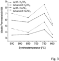
- Fig. 3
- aus den Einzelgaspermeanzmessungen errechnete idealen Permselektivitäten von H2/SF6 und He/SF6 für MFI-Membranen
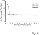
- Fig. 4
- Permporosimetriemessung an einer keramischen Membran mit 0,9 nm Porendurchmesser vor und nach der Kohlenstoffinfiltration über Infiltration und Pyrolyse eines flüssigen Prekursors
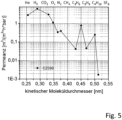
- Fig. 5
- Einzelgaspermeationsmessung an einer kohlenstoffinfiltrierten Zeolithmembran hergestellt durch Infiltration und Pyrolyse eines flüssigen Prekursors in eine Nanozeolithschicht
- Fig. 6
- Permeanzen in binären 50:50 Gemischen aus H2O und N2, H2O und CH4, H2O und CO2 sowie H2O und H2 sowie dazugehörige H2O/N2-, H2O/CH4-, H2O/CO2- und H2O/H2-Permselektivitäten gemessen bei 200 °C, einem Feeddruck von 11 bar absolut und einem Permeatdruck von 1 bar bis 4 bar absolut an einer kohlenstoffinfiltrierten Zeolithmembran hergestellt durch Infiltration und Pyrolyse eines flüssigen Prekursors in eine Nanozeolithschicht (MFI)
- Fig. 7
- Permeanzen der Einzelgase (He, CO2 und N2) und Mischgase (CO2:N2 1:1 und 1:5) und der daraus resultierenden idealen und realen Selektivität für die Trennung der Gase CO2 und N2 bei 25 °C einer SAPO-34 Membran (SAPO-34/M), einer kohlenstoff-integrierten SAPO-34 Zeolithmembran (SAPO-34/CiZM, Infiltration durch Eintauchen) und eines kohlenstoff-integrierten α-Al2O3Trägers (CiAl2O3) und
- Fig. 8
- Ramanspektrum eines kohlenstoff-integrierten α-Al2O3Trägers (CiAl2O3) und einer kohlenstoff-integrierten SAPO-34 Zeolithmembran (SAPO-34/CiZM).
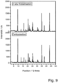
- Fig. 9
- XRD-Diffraktogramm einer SAPO-34 Zeolithmembran sowie einer kohlenstoff-integrierten SAPO-34 Zeolithmembran (SAPO-34/CiZM)
- Wie bereits in der Beschreibungseinleitung beschrieben, benötigt eine Zeolithmembran einen Träger, welcher dem System mechanische Stabilität verleiht, ohne jedoch die Trennung oder den Stofftransport zu beeinflussen. Deshalb wird die Herstellung unterschiedlicher Träger vorangestellt, auf in den nachfolgenden Ausführungsbeispielen Bezug genommen wird:
- 1a) Eine über keramisches Folienziehen hergestellte poröse, keramische Tablette aus α-Al2O3 mit einem mittleren Porendurchmesser von 3 µm einem Durchmesser der Tablette von 18 mm und einer Dicke von 2 mm wurde schrittweise mit keramischen Schlickern aus α-Al2O3-Pulvern abnehmender Partikelgröße über Schleuderbeschichtung und anschließendes Sintern einseitig beschichtet, bis eine finale Deckschicht mit einem mittleren Porendurchmesser von 200 nm aufgebracht war.
- 1b) Ein über extrudieren hergestelltes poröses, keramisches Rohr aus α-Al2O3 mit einem mittleren Porendurchmesser von 3 µm einem Außendurchmesser von 10 mm, einem Innendurchmesser von 7 mm und einer Länge von 100 mm wurde schrittweise mit keramischen Schlickern aus α-Al2O3-Pulvern abnehmender Partikelgröße durch Schlickergießen und anschließendes Sintern auf der Innenseite beschichtet, bis eine finale Deckschicht mit einem mittleren Porendurchmesser von 100 nm aufgebracht war. Auf diese Deckschicht wurde ein kolloidales über einseitiges Tauchbeschichten aus einem kolloidalen Böhmitsol eine Gelschicht abgeschieden, die nach der Sinterung eine finale γ-Al2O3-Schicht mit einem mittleren Porendurchmesser zwischen 2 nm und 5 nm ergab.
- 1c) Ein Rohr gemäß Ausführungsbeispiel 1b) wurde nach der Beschichtung mit der 100 nm α-Al2O3-Schicht schrittweise mit einem kolloidalen TiO2-, einem kolloidalen ZrO2 und einem polymeren TiO2-Sol beschichtet und jeweils zwischendurch thermisch behandelt. Die finale Deckschicht war aus amorphen TiO2 und hatte einen mittleren Porendurchmesser von 0,9 nm.
- Eine Membran aus Ausführungsbeispiel 1b) wurde einem Abscheideprozess aus der Gasphase (Chemical Vapor Deposition, CVD) wie folgt unterzogen: Die Membran wurde in der heizkonstanten Zone eines Vertikalofens platziert. Bevor der Abscheideprozess startete, wurde eine Inertatmosphäre durch Spülen mittels Stickstoff geschaffen. Nach ausreichendem Spülen wurde der Ofen mit darin enthaltener Membran und inerter Atmosphäre auf Abscheidetemperatur von 650 °C geheizt. Nach Erreichen dieser, wurde die Gaszusammensetzung von 100 % Stickstoff auf 96,4 % Stickstoff (99,8 %, Linde) und 3,6 % Acetylen (99,6 %, Air Liquide) geändert. Die Dauer dieser Behandlung dauerte 30 min. Im Anschluss an die Kohlenstoffabscheidung wurde die Atmosphäre auf 100 % Stickstoff geändert und der Ofen kühlte auf Raumtemperatur ab, bevor die Probe entnommen wurde. Der analytische Nachweis erfolgte mittels Permporosimetrie mit He als permeable und n-Hexan als kondensierende Phase (
Fig. 1 ). - Es zeigte sich, dass erwartungsgemäß die Ausgangsmembran einen Porendurchmesser von < 3 nm aufwies. Die He-Trockengaspermeanz lag bei ca. 180 m3/(m2·h·bar). Nach der Blockierung aller Poren < 3 nm fiel die He Permeanz auf ca. 0,42 m3/(m2·h·bar) was ca. 0,2% der Ausgangspermeanz entsprach. Die verbliebene Permeation entsprach dem Gasfluss durch Defekte >3 nm. Nach der Kohlenstoffabscheidung sank die He-Trockengaspermeation um den Faktor 30 auf ca. 6 m3/(m2·h·bar). Bereits mit den ersten 4 n-Hexan-Befeuchtungsschritten fiel die He-Permeanz auf ca. 0,4 m3/(m2·h·bar) um dann bei weiterer Befeuchtung weitestgehend konstant zu bleiben. Folglich war es durch die Kohlenstoffinfiltration mittels CVD-Verfahren bereits gelungen, Poren mit einem Durchmesser <3 nm auf einen Durchmesser <1 nm zu reduzieren. Größere Poren hingegen wurden nicht blockiert. Die angewendete Methode zur CVD-Abscheidung von Kohlenstoff eignet sich folglich zum Reduzieren des Durchmessers von Poren, die sich im Größenordnungsbereich von Defekten und Zwischenkornporen von Zeolithmembranen befinden.
- Ein poröses keramisches Rohr mit einer finalen Deckschicht aus α-Al2O3 mit einem mittleren Porendurchmesser von 100 nm wurde über Schlickergießen mit einem Gemisch aus Silikalith-Partikeln, einem kolloidalen Kieselsol und Wasser im Masseverhältnis 1 :4:15 auf der Rohrinnenseite beschichtet. Die Schicht wurde bei 450 °C unter Luft eingebrannt. Anschließend erfolgte über 24 h bei 180 °C eine hydrothermale Behandlung im geschlossenen, teflonausgekleideten Autoklavbehälter in einer Lösung bestehend aus kolloidalem Kieselsol, Aluminium (Merck), Tetrapropylammoniumhydroxid (TPAOH 25%, Acros Organics), Tetrapropylammoniumbromid (>98 % TPABr, Alfa Aesar), Natriumhydroxidplätzchen (>99 %, VWR) und Wasser (deionisiert) im stöchiometrischen Verhältnis 90 SiO2 / 0,225 Al2O3 / 1 Na2O / 4,15 TPAOH / 1,85 TPABr / 1990 H2O. Die entstehende MFI-Membran wurde bei 450 °C an Luft detemplatisiert.
- Die MFI-Membran wurde entsprechend Ausführungsbeispiel 2 einer CVD-Behandlung mit einem 2,4 %igen Acetylen-Stickstoffgemisch unterzogen bei einer Abscheidedauer von 45 min und der Abscheidetemperatur von 750 °C. Sowohl die hergestellten als auch die behandelten Membranen wurden mittels Einzelgaspermeationsmessung mit ausgewählten Gasen untersucht.
- Bei Einzelgaspermeanzen in
Fig. 2 wird deutlich, dass durch die CVD-Behandlung die Permeanzen aller Gase abnehmen und die ideale He/SF6 Permselektivität von 4,5 auf 6,0 steigt. Diese Verbesserung erklärt sich durch ein kontrolliertes Verblocken von Defektporen bzw. Fehlstellen. - Eine MFI-Membran gemäß Ausführungsbeispiel 2 wurde mit n-Hexan (>99 %, Merck) als Dampfphase behandelt. Dazu wurde ein Stickstoffstrom mit n-Hexan beladen und für 45 min über die Membran geleitet wobei eine anliegende Temperatur von 550 - 800 °C für eine sofortige Pyrolyse des auskondensierenden n-Hexan führen sollte. Für alle Pyrolysetemperaturen konnte eine eindeutige Erhöhung der idealen H2/SF6- und He/SF6-Permselektivitäten ermittelt werden, was auf ein Verblocken der Zwischenkornporen zurückzuführen ist (
Fig. 3 ). - Eine Membran gemäß 1c) wurde mit einer Mischung aus Phenolharzpulver (0235DP, Momentive) gelöst in Methanol (Merck) und 1-Methyl-2-pyrolidon (Merck) im Masseverhältnis 3,25:22,5:20 durch Einfüllen der Mischung in das keramische Membranrohr infiltriert. Anschließend erfolgte eine thermische Behandlung bei 150 °C zur Vernetzung des Phenolharzes gefolgt von einer Pyrolyse unter Ar bei 740 °C. Die Ausgangsmembran sowie die mit Kohlenstoff infiltrierte Membran wurde mittels Permporometrie unter Verwendung von He als Gasphase und n-Hexan als kondensierende Phase untersucht. Es zeigte sich, dass erwartungsgemäß die Ausgangsmembran einen Porendurchmesser von <2 nm aufwies. Die He-Trockengaspermeanz lag bei ca. 350 m3/(m2·h·bar). Nach der Blockierung aller Poren <2 nm fiel die He Permeanz auf ca. 12 m3/(m2·h·bar) was ca. 3% der Ausgangspermeanz entsprach. Die verbliebene Permeation entsprach dem Gasfluss durch Defekte > 2 nm. Die Permeanz durch Defekte > 4 nm betrug ca. 10 m3/(m2·h·bar) und somit 2 % der He-Trockengaspermeanz. Nach der Kohlenstoffabscheidung sank die He-Trockengaspermeation um den Faktor 30 auf ca. 12 m3/(m2·h·bar). Mit zunehmender n-Hexan-Befeuchtung war nur eine leichte Abnahme der He-Permeanz zu beobachten. Für Poren >4 nm lag die He-Permeanz identisch zur Membran ohne Kohlenstoffinfiltration bei 10 m3/(m2·h·bar). Folglich war es durch die Kohlenstoffinfiltration gelungen, Poren mit einem Durchmesser <4 nm weitestgehend zu blockieren. Größere Poren hingegen wurden nicht blockiert. Die angewendete Methode der Infiltration einer Membran mit einem flüssigen Prekursor und anschließende Pyrolyse eignet sich folglich zum Blockieren kleiner Poren, die sich im Größenordnungsbereich von Defekten und Zwischenkornporen von Zeolithmembranen befinden.
- Eine rohrförmige, keramische Membran mit einer finalen Schicht aus γ-Al2O3 mit einem mittleren Porendurchmesser zwischen 2 nm und 5 nm gemäß 1b) wurden mit einer Schicht aus Zeolith-Nanokristallen hergestellt durch hydrothermale Synthese bei 60 °C über 14 Tagen in einer Mischung aus TPAOH, TPABr und TEOS (>99 %, ABCR) in einem molaren Verhältnis von 25 SiO2 : 9 TPAOH : 360 H2O : 100 Ethanol nach Person et al., Zeolites, 1994, Vol 14, Sept/Oct, 557-567 , beschichtet. Die Beschichtung erfolgte durch Anheften der 50 nm bis 60 nm großen MFI-Kristalle an den porösen keramischen Untergrund unter Zuhilfenahme von Dimethylammoniumchlorid (65% in Wasser, Fluka) gemäß Hedlund et al.; J. Membr. Sc. 159 (1999) 263 . Die so erhaltene Zeolithnanoschicht wurde bei 450 °C unter Luft kalziniert. Die Probe wurde anschließend mit Phenolharzpulver (0235DP, Momentive) gelöst in Methanol (Merck) und 1-Methyl-2-pyrolidon (Merck) im Masseverhältnis 3,25:22,5:20 einseitig infiltriert, gefolgt von einer Polymerisation bei 150 °C und einer Pyrolyse unter Ar bei 740 °C. Die erhaltene Kohlenstoffinfiltrierte Zeolithmembran wurde mittels Einzelgaspermeation bei 150 °C untersucht. Es zeigte sich eine He-Permeanz von 3 m3/(m2·h·bar), eine H2-Permeanz von 6 m3/(m2·h·bar) und eine SF6-Permeanz von ca. 0,002 m3/(m2·h·bar). Mit einer idealen He/SF6-Permselektivität von ca. 1.650 und einer idealen H2/SF6-Permselektivität von ca. 3.600 liegt eine kohlenstoffinfiltrierte Zeolithmembran mit molsiebenden Trenneigenschaften vor. (
Fig. 5 ) - Eine derart hergestellte Membran wird anschließend bei 200 °C mit Gasgemischen, bestehend zu je 50 % aus H2O und N2, H2O und CH4, H2O und CO2 sowie H2O und H2 bei 11 bar absolut beaufschlagt. Auf der Rückseite der Membran lag atmosphärischer Druck (1 bar absolut) oder ein leichter Überdruck (4 bar absolut) an. Der durch die
- Membran hindurchtretende Gasstrom wurde durch eine Kühlfalle (-10 °C) geleitet, in der auftretendes Wasser auskondensiert wurde. Der verbliebene Gasstrom wurde mit einem multiscalen Blasenzählrohr gemessen. Es zeigte sich, dass nach dem Umschalten von einem Gasgemisch auf das nächste Gasgemisch nach kurzer Experimentierzeit, die Permeation des Gases CO2 um den Faktor 10, die Permeation der Gase N2, CH4 und H2 bis unterhalb der Messgrenze sank wohingegen die Wasserpemeation immer im erheblich höheren Permeationsbereich verblieb oder sogar stieg. Entsprechend wurden unendlich hohe H2O/N2-, H2O/CH4-, H2O/H2-Permselektivitäten sowie eine H2O/CO2-Permselektivität von 400 gemessen. Die Membran ist also in jedem Fall permeabel für Wasser, für andere Gase jedoch erheblich geringer permeabel bis vollkommen impermeabel (
Fig. 6 ). - Zur Herstellung einer Zeolithmembran, die aus der aktiven Komponente SAPO-34 und einer porösen Trägerstruktur, α-Aluminiumoxid besteht, wird eine in-situ Kristallisation mittels hydrothermaler Synthese durchgeführt. Hierzu wird zunächst eine Syntheselösung wie folgt hergestellt: Das strukturdirigierende Agens (SDA), Tetraethylammoniumhydroxid (TEA-OH, 35 wt%, Sigma Aldrich) wird vorgelegt und mit der Siliziumquelle, Tetraethylorthosilikat (TEOS, 99 %, Alfa Aesar) und dem zusätzlich benötigten destilliertem Wasser versetzt. Diese erhaltene Lösung A wird für 10 min bei 600 rpm gerührt. Unter weiterem Rühren bei 600 rpm erfolgt die langsame Zugabe der Aluminiumquelle, Aluminiumisopropoxid (Al-isopropoxid zur Synthese, 98 %, Merck) und die entstehende Lösung B wird für weitere zwei Stunden gerührt. Zu dieser Lösung B wird die Phosphorquelle, ortho-Phosphorsäure (85 wt%, VWR) zugetropft. Die erhaltene Lösung C mit einer resultierenden molaren Zusammensetzung von 1,0 Al2O3 : 4,0 P2O5: 0,6 SiO2 : 2,0 TEA-OH : 139 H2O wird unter Rühren bei 600 rpm für 30 min gealtert. Anschließend werden 30 ml dieser gealterten Lösung C in einen Edelstahlautoklaven (45 ml, 4744, Parr Instruments) mit Tefloneinsatz überführt, in dem sich bereits der zu bekeimende α-Aluminiumoxid Träger gemäß 1 a) befindet. Die nachfolgende hydrothermale Synthese - in-situ Kristallisation - erfolgt statisch bei 180 °C für 48 h. Nach der benötigten Synthesezeit wird die erhaltenen SAPO-34 Membran (Träger, der innerhalb der in-situ Kristallisation mit SAPO-34 belegt wurde) von dem entstehenden SAPO-34 Überschusspulver mittels Zentrifugation abgetrennt. Die so synthetisierte SAPO-34 Membran wird zunächst bei 75 °C getrocknet und anschließend zur Templatentfernung kalziniert. Innerhalb des Kalzinierungsvorganges wird die SAPO-34 Membran unter Luft mit einer Heizrate von 0,2 K min-1 auf 400 °C erhitzt, dieser Temperatur für 16 h ausgesetzt und anschließend langsam abgekühlt. Die Lagerung der hergestellten SAPO-34 Membran erfolgt in einem auf 100 °C geheizten Ofen.
- Ausgehend von einer Zeolithmembran erfolgt die Herstellung einer kohlenstoffintegrierten Zeolithmembran durch zwei Verfahrensschritte:
- 1. Flüssiginfiltration der Zeolithmembran
- 2. Karbonisierung der infiltrierten Zeolithmembran
- Zur Infiltrierung der hergestellten SAPO-34 Membran wird zunächst eine Lösung aus dem Monomer Furfurylalkohol (> 98,0 %, Merck) und Salpetersäure (HNOs, 65 wt%, Fluka) hergestellt. Hierzu wird der Furfurylalkohl vorgelegt und unter Rühren die benötigte Menge Salpetersäure hinzugetropft. Unter weiterem Rühren erfolgt eine Vorpolymerisierung dieser Lösung von 40 min. Nachfolgend wird die hergestellte SAPO-34 Membran für 5 min in diese Lösung eingetaucht. Die infiltrierten SAPO-34 Membranen werden zunächst zur Vernetzung der Polymere für 16 h bei 75 °C getrocknet und anschließend karbonisiert. Die Karbonisierung findet in Stickstoffatmosphäre bei 500 °C für 16 h statt. Die Heizrate beträgt hierbei ebenfalls 0,2 K min-1.
- Als Vergleichssystem zu den hergestellten kohlenstoff-integrierten Zeolithmembranen wird ausgehend von einem α-Al2O3 Träger mit einer Porengröße von 200 nm nach 1a) ein kohlenstoff-integrierter α-Al2O3 Träger (CiAl2O3) hergestellt. Wie unter Ausführungsbeispiel 7 wird der α-Al2O3 Träger in eine vorpolymerisierte Lösung aus Furfurylalkohl und Salpetersäure getaucht, getrocknet und anschließend karbonisiert. Die hergestellte SAPO-34 Membran (SAPO-34/M, Ausführungsbeispiel 6), die kohlenstoff-integrierten SAPO-34 Membranen (SAPO-34/CiZM, Ausführungsbeispiel 7) sowie der kohlenstoff-integrierte α-Al2O3 Träger (CiAl2O3, Ausführungsbeispiel 8) werden mittels Permeanzmessungen von Einzelgasen und Mischgasen bei unterschiedlichen 25 °C) charakterisiert (
Fig. 7 ) und daraus Selektivitäten für die Trennung von CO2 und N2 bestimmt. - Die reine SAPO-34-Membran wies sehr hohe Permeanzen im Größenordnungsbereich um 2 × 10⁻⁵ mol/(m2·s·Pa) (Einzelgaspermeation) bzw. um 7 × 10⁻⁷ mol/(m2·s·Pa) (Mischgaspermeation). Mit Permselektivitäten um 1 trat nahezu keine selektive Stofftrennung auf. Durch die Integration von Kohlenstoff sanken die Permeanzen auf Werte von 0,5 × 10⁻⁸ mol/(m2·s·Pa) (N2) bis 5 × 10⁻⁸ mol/(m2·s·Pa) (CO2) und die Permselektivitäten stiegen auf 9 (ideale Permselektivität der Einzelgasmessung) bis 14 bzw. 15 (Mischgasmessungen) was einer überaus selektiv trennenden Membran entspricht. Eine mit Kohlenstoff integrierte α-Al2O3-Membran mit einem Porendurchmesser von 200 nm wies hingegen nur Selektivitäten zwischen 1 und 2 auf. Folglich handelt es sich bei den Trenneigenschaften der kohlenstoffintegrierten Zeolithmembran um die Trenneigenschaften der Zeolithkristalle, deren Zwischenkornporen durch Kohlenstoff blockiert waren.
- Die hergestellten Kohlenstoffspezies wurden weiterführend mittels Ramanspektroskopie untersucht. Die Ramanspektren beider Proben (in infiltrierter α-Al2O3-Träger mit 200 nm Poren und in Zwischenkornporen der infiltrierten Zeolithmembran) zeigen die für Kohlenstoff typischen Banden bei ca. 1350 cm-1 und bei ca. 1590 cm-1. Die Bande bei 1590 cm-1 repräsentiert die Streckschwingung sp2 hybridisierter Kohlenstoffbindungen in der Ebene. In amorphen Strukturen lässt sich neben dieser Bande eine weitere bei 1350 cm-1 erkennen, die eine andere Symmetrie aufweist. Die Ramanspektren deuten auf eine amorphe Struktur von Kohlenstoff hin (
Fig. 8 ). - Eine reine Zeolithmembran auf α-Al2O3-Träger mit 200 nm Poren (SAPO-34/M) und eine nachträglich mit Kohlenstoff behandelte Zeolithmembran (SAPO-34(CiZM) wurden mittels Röntgendiffraktometrie untersucht (
Fig. 9 ). In beiden Diffraktogramme konnten nur die charakteristischen Röntgenreflexe des Zeolithen und der α-Al2O3-Trägerkeramik gefunden werden. Der Kohlenstoff war nicht als kristalline Spezies auffindbar. Folglich handelte es sich beim infiltrierten Kohlenstoff um röntgenamorphen Kohlenstoff.
wobei der röntgenamorphe Kohlenstoff keine messbare Porosität aufweist oder dessen Poren kleiner sind als die Zeolithporen.
Claims (4)
- Permeationsmembran bestehend aus einem Träger und einer kristallinen Substanz mit Zeolithstruktur, die Zeolithporen, Zwischenkornporen und Defekte aufweist,dadurch gekennzeichnet, dass in die kristalline Substanz mit Zeolithstruktur ein röntgenamorpher Kohlenstoff derart stellenweise eingelagert ist, dass die vorhandenen Zwischenkornporen und Defekte in der kristallinen Substanz durch den röntgenamorphen Kohlenstoff mindestens teilweise ausgefüllt sind,wobei ein Einbringen des röntgenamorphen Kohlenstoffs in die Zwischenkornporen und Defekte der kristallinen Substanz mit Zeolithstruktur durch- Infiltration eines organischen Precursors und anschließende Pyrolyse unter inerten Bedingungen, oder- Kondensation eines dampfförmigen, organischen Precursors und anschließender Pyrolyse unter inerten Bedingungen, oder- reaktives Abscheiden einer verdampften organischen Spezies aus der Gasphase durch chemische Gasphasenabscheidung (CVD) unter inerten Bedingungen bei 500-1000°C, oder- Pyrolyse unter inerten Bedingungen überschüssigen Templates aus der Synthese der Zeolithstruktur erfolgt ist,wobei der röntgenamorphe Kohlenstoff keine messbare Porosität aufweist oder dessen Poren kleiner sind als die Zeolithporen.
- Permeationsmembran nach Anspruch 1, dadurch gekennzeichnet, dass es sich bei den kristallinen Substanzen mit Zeolithstruktur um Vertreter der Strukturen SOD, LTA, ERI, CHA, MFI und FAU handelt.
- Verfahren zur Herstellung einer Permeationsmembran nach den Ansprüchen 1 oder 2, mit den Schritten:a) Herstellen einer Zeolithmembran, die Zeolithporen, Zwischenkornporen und Defekte aufweist,b) Einbringen eines röntgenamorphen Kohlenstoffs nur in die Zwischenkornporen und Defekte der Zeolithmembran;wobei das Einbringen des röntgenamorphen Kohlenstoffs in die Zwischenkornporen und Defekte der Zeolithmembran durch- Infiltration eines organischen Precursors und anschließende Pyrolyse unter inerten Bedingungen, oder- Kondensation eines dampfförmigen, organischen Precursors und anschließender Pyrolyse unter inerten Bedingungen, oder- reaktives Abscheiden einer verdampften organischen Spezies aus der Gasphase durch chemische Gasphasenabscheidung (CVD) unter inerten Bedingungen bei 500-1000°C oder- Pyrolyse unter inerten Bedingungen, überschüssigen Templates aus der Synthese der Zeolithstruktur, erfolgt,wobei der röntgenamorphe Kohlenstoff keine messbare Porosität aufweist oder dessen Poren kleiner sind als die Zeolithporen.
- Verwendung einer nach Anspruch 3 hergestellten Permeationsmembran zur Abtrennung von Wasser durch Permeation durch die Permeationsmembran aus Gemischen von Wasser mit Wasserstoff und/ oder Stickstoff und/ oder Methan und/oder Kohlendioxid.
Applications Claiming Priority (2)
| Application Number | Priority Date | Filing Date | Title |
|---|---|---|---|
| DE102016103645 | 2016-03-01 | ||
| PCT/DE2017/100156 WO2017148473A1 (de) | 2016-03-01 | 2017-02-28 | Permeationsmembran und verfahren zur herstellung einer permeationsmembran |
Publications (2)
| Publication Number | Publication Date |
|---|---|
| EP3423174A1 EP3423174A1 (de) | 2019-01-09 |
| EP3423174B1 true EP3423174B1 (de) | 2024-08-21 |
Family
ID=58632106
Family Applications (1)
| Application Number | Title | Priority Date | Filing Date |
|---|---|---|---|
| EP17719151.7A Active EP3423174B1 (de) | 2016-03-01 | 2017-02-28 | Permeationsmembran und verfahren zur herstellung einer permeationsmembran |
Country Status (4)
| Country | Link |
|---|---|
| US (1) | US20190070568A1 (de) |
| EP (1) | EP3423174B1 (de) |
| JP (1) | JP2019508241A (de) |
| WO (1) | WO2017148473A1 (de) |
Families Citing this family (4)
| Publication number | Priority date | Publication date | Assignee | Title |
|---|---|---|---|---|
| JP2018167150A (ja) * | 2017-03-29 | 2018-11-01 | 旭化成株式会社 | ガス分離膜 |
| JP7220087B2 (ja) * | 2018-03-30 | 2023-02-09 | 日本碍子株式会社 | ゼオライト膜複合体、ゼオライト膜複合体の製造方法、および、分離方法 |
| JP7275852B2 (ja) * | 2018-05-22 | 2023-05-18 | 三菱ケミカル株式会社 | 多孔質支持体-ゼオライト膜複合体 |
| WO2022029888A1 (ja) * | 2020-08-04 | 2022-02-10 | 積水化学工業株式会社 | ガス製造装置、ガス製造システムおよびガス製造方法 |
Family Cites Families (9)
| Publication number | Priority date | Publication date | Assignee | Title |
|---|---|---|---|---|
| DE69533510T2 (de) | 1994-07-08 | 2005-09-15 | Exxon Research And Engineering Co. | Zeolith enthaltende zusammensetzung mit einer selektivität erhhöhenden beschichtung |
| US5672388A (en) * | 1994-07-08 | 1997-09-30 | Exxon Research & Engineering Company | Membrane reparation and poer size reduction using interfacial ozone assisted chemical vapor deposition |
| JP2001031416A (ja) * | 1998-08-28 | 2001-02-06 | Toray Ind Inc | ゼオライト膜の製造方法、mfi型ゼオライト膜および分子を分離する方法 |
| EP1118378A1 (de) | 1998-08-28 | 2001-07-25 | Toray Industries, Inc. | Übertragbarer film, elektrolytischer katalysator, verfahren zur herstellung von zeolith-filmen, mfi-zeolithfilm und veffahren zur trennung |
| JP2001029760A (ja) * | 1998-08-28 | 2001-02-06 | Toray Ind Inc | 透過膜、電解コンデンサ、透過膜の処理方法、及び分離方法 |
| US6494326B1 (en) * | 2000-06-15 | 2002-12-17 | Sandia Corporation | Composite zeolite membranes |
| US7041616B1 (en) * | 2002-04-12 | 2006-05-09 | Sandia Corporation | Enhanced selectivity of zeolites by controlled carbon deposition |
| ATE471922T1 (de) * | 2003-10-17 | 2010-07-15 | Univ Delft Tech | Verfahren zur abtrennung von wasser aus einem reaktionsgemisch unter verwendung einer hydroxy- sodalit-membran |
| JP2010115610A (ja) * | 2008-11-14 | 2010-05-27 | Sumitomo Electric Ind Ltd | ゼオライト複合分離膜及びその製造方法 |
-
2017
- 2017-02-28 JP JP2018545885A patent/JP2019508241A/ja active Pending
- 2017-02-28 WO PCT/DE2017/100156 patent/WO2017148473A1/de not_active Ceased
- 2017-02-28 US US16/081,070 patent/US20190070568A1/en not_active Abandoned
- 2017-02-28 EP EP17719151.7A patent/EP3423174B1/de active Active
Also Published As
| Publication number | Publication date |
|---|---|
| US20190070568A1 (en) | 2019-03-07 |
| JP2019508241A (ja) | 2019-03-28 |
| EP3423174A1 (de) | 2019-01-09 |
| WO2017148473A1 (de) | 2017-09-08 |
Similar Documents
| Publication | Publication Date | Title |
|---|---|---|
| Hedlund et al. | High-flux MFI membranes | |
| Mirfendereski et al. | High-performance MFI zeolite hollow fiber membranes synthesized by double-layer seeding with variable temperature secondary growth | |
| Wang et al. | Ultrafast synthesis of thin all-silica DDR zeolite membranes by microwave heating | |
| EP3225297B1 (de) | Verwendung eines komplex aus porösem träger und cha zeolithmembran zur trennung eines gasgemisches | |
| Xia et al. | Microstructure manipulation of MFI-type zeolite membranes on hollow fibers for ethanol–water separation | |
| EP1706197B1 (de) | Komposit-membran | |
| Banihashemi et al. | B-oriented MFI zeolite membranes for xylene isomer separation-Effect of xylene activity on separation performance | |
| EP2032239A1 (de) | Verfahren zur herstellung einer komposit-membran | |
| Hedlund et al. | A masking technique for high quality MFI membranes | |
| US20130064747A1 (en) | Zeolite ddr membranes | |
| EP2621616B1 (de) | Kohlenstoffmembranen | |
| DE69533510T2 (de) | Zeolith enthaltende zusammensetzung mit einer selektivität erhhöhenden beschichtung | |
| JPWO2016121888A1 (ja) | 分離膜構造体 | |
| EP3423174A1 (de) | Permeationsmembran und verfahren zur herstellung einer permeationsmembran | |
| WO2006105771A1 (de) | Membran für gasphasenseparation sowie dafür geeignetes herstellungsverfahren | |
| DE112020001419T5 (de) | Zeolithmembrankomplex, Verfahren zur Herstellung eines Zeolithmembrankomplexes, Verfahren zur Behandlung eines Zeolithmembrankomplexes und Trennverfahren | |
| EP2621610B1 (de) | Verfahren zur herstellung von kohlenstoffmembranen | |
| Wang et al. | Exfoliation of lamellar SAPO-34 zeolite to nanosheets and synthesis of thin SAPO-34 membranes by a nanosheet-seeded secondary growth approach | |
| Chai et al. | Ethanol perm‐selective B‐ZSM‐5 zeolite membranes from dilute solutions | |
| Ma et al. | Improved silicalite-1 membranes on 61-channel monolithic supports for n-butane/i-butane separation | |
| O’Brien-Abraham et al. | A comparative study on permeation and mechanical properties of random and oriented MFI-type zeolite membranes | |
| US20180369746A1 (en) | Method for separating carbon dioxide and apparatus for separating carbon dioxide | |
| Vaezi et al. | Separation of CO2 and N2 from CH4 using modified DD3R zeolite membrane: A comparative study of synthesis procedures | |
| EP3037157B1 (de) | Kohlenstoffmembran, verfahren zur herstellung von kohlenstoffmembranen und deren verwendung | |
| WO2020058154A1 (de) | Cms-membran, verfahren zu ihrer herstellung und ihre verwendung |
Legal Events
| Date | Code | Title | Description |
|---|---|---|---|
| STAA | Information on the status of an ep patent application or granted ep patent |
Free format text: STATUS: UNKNOWN |
|
| STAA | Information on the status of an ep patent application or granted ep patent |
Free format text: STATUS: THE INTERNATIONAL PUBLICATION HAS BEEN MADE |
|
| PUAI | Public reference made under article 153(3) epc to a published international application that has entered the european phase |
Free format text: ORIGINAL CODE: 0009012 |
|
| STAA | Information on the status of an ep patent application or granted ep patent |
Free format text: STATUS: REQUEST FOR EXAMINATION WAS MADE |
|
| 17P | Request for examination filed |
Effective date: 20180921 |
|
| AK | Designated contracting states |
Kind code of ref document: A1 Designated state(s): AL AT BE BG CH CY CZ DE DK EE ES FI FR GB GR HR HU IE IS IT LI LT LU LV MC MK MT NL NO PL PT RO RS SE SI SK SM TR |
|
| AX | Request for extension of the european patent |
Extension state: BA ME |
|
| RIN1 | Information on inventor provided before grant (corrected) |
Inventor name: REIF, BENJAMIN Inventor name: LUEDKE, DIRK Inventor name: SCHUELEIN, MARION Inventor name: JUETTKE, YVONNE Inventor name: SCHWIEGER, WILHELM Inventor name: SIMON, ADRIAN Inventor name: RICHTER, HANNES |
|
| RIN1 | Information on inventor provided before grant (corrected) |
Inventor name: LUEDKE, DIRK Inventor name: SIMON, ADRIAN Inventor name: JUETTKE, YVONNE Inventor name: SCHUELEIN, MARION Inventor name: REIF, BENJAMIN Inventor name: SCHWIEGER, WILHELM Inventor name: RICHTER, HANNES |
|
| DAV | Request for validation of the european patent (deleted) | ||
| DAX | Request for extension of the european patent (deleted) | ||
| STAA | Information on the status of an ep patent application or granted ep patent |
Free format text: STATUS: EXAMINATION IS IN PROGRESS |
|
| RAP3 | Party data changed (applicant data changed or rights of an application transferred) |
Owner name: FRIEDRICH-ALEXANDER-UNIVERSITAET ERLANGEN-NUERNBERG Owner name: FRAUNHOFER-GESELLSCHAFT ZUR FOERDERUNG DER ANGEWANDTEN FORSCHUNG E.V. |
|
| 17Q | First examination report despatched |
Effective date: 20220404 |
|
| GRAP | Despatch of communication of intention to grant a patent |
Free format text: ORIGINAL CODE: EPIDOSNIGR1 |
|
| STAA | Information on the status of an ep patent application or granted ep patent |
Free format text: STATUS: GRANT OF PATENT IS INTENDED |
|
| INTG | Intention to grant announced |
Effective date: 20240320 |
|
| GRAS | Grant fee paid |
Free format text: ORIGINAL CODE: EPIDOSNIGR3 |
|
| GRAA | (expected) grant |
Free format text: ORIGINAL CODE: 0009210 |
|
| STAA | Information on the status of an ep patent application or granted ep patent |
Free format text: STATUS: THE PATENT HAS BEEN GRANTED |
|
| AK | Designated contracting states |
Kind code of ref document: B1 Designated state(s): AL AT BE BG CH CY CZ DE DK EE ES FI FR GB GR HR HU IE IS IT LI LT LU LV MC MK MT NL NO PL PT RO RS SE SI SK SM TR |
|
| REG | Reference to a national code |
Ref country code: GB Ref legal event code: FG4D Free format text: NOT ENGLISH |
|
| REG | Reference to a national code |
Ref country code: CH Ref legal event code: EP |
|
| REG | Reference to a national code |
Ref country code: DE Ref legal event code: R096 Ref document number: 502017016362 Country of ref document: DE |
|
| REG | Reference to a national code |
Ref country code: IE Ref legal event code: FG4D Free format text: LANGUAGE OF EP DOCUMENT: GERMAN |
|
| REG | Reference to a national code |
Ref country code: DE Ref legal event code: R081 Ref document number: 502017016362 Country of ref document: DE Owner name: FRIEDRICH-ALEXANDER-UNIVERSITAET ERLANGEN-NUER, DE Free format text: FORMER OWNER: ANMELDERANGABEN UNKLAR / UNVOLLSTAENDIG, 80297 MUENCHEN, DE Ref country code: DE Ref legal event code: R081 Ref document number: 502017016362 Country of ref document: DE Owner name: FRAUNHOFER-GESELLSCHAFT ZUR FOERDERUNG DER ANG, DE Free format text: FORMER OWNER: ANMELDERANGABEN UNKLAR / UNVOLLSTAENDIG, 80297 MUENCHEN, DE |
|
| REG | Reference to a national code |
Ref country code: SE Ref legal event code: TRGR |
|
| REG | Reference to a national code |
Ref country code: LT Ref legal event code: MG9D |
|
| REG | Reference to a national code |
Ref country code: NL Ref legal event code: MP Effective date: 20240821 |
|
| PG25 | Lapsed in a contracting state [announced via postgrant information from national office to epo] |
Ref country code: NO Free format text: LAPSE BECAUSE OF FAILURE TO SUBMIT A TRANSLATION OF THE DESCRIPTION OR TO PAY THE FEE WITHIN THE PRESCRIBED TIME-LIMIT Effective date: 20241121 |
|
| PG25 | Lapsed in a contracting state [announced via postgrant information from national office to epo] |
Ref country code: NL Free format text: LAPSE BECAUSE OF FAILURE TO SUBMIT A TRANSLATION OF THE DESCRIPTION OR TO PAY THE FEE WITHIN THE PRESCRIBED TIME-LIMIT Effective date: 20240821 Ref country code: FI Free format text: LAPSE BECAUSE OF FAILURE TO SUBMIT A TRANSLATION OF THE DESCRIPTION OR TO PAY THE FEE WITHIN THE PRESCRIBED TIME-LIMIT Effective date: 20240821 Ref country code: PL Free format text: LAPSE BECAUSE OF FAILURE TO SUBMIT A TRANSLATION OF THE DESCRIPTION OR TO PAY THE FEE WITHIN THE PRESCRIBED TIME-LIMIT Effective date: 20240821 Ref country code: PT Free format text: LAPSE BECAUSE OF FAILURE TO SUBMIT A TRANSLATION OF THE DESCRIPTION OR TO PAY THE FEE WITHIN THE PRESCRIBED TIME-LIMIT Effective date: 20241223 Ref country code: GR Free format text: LAPSE BECAUSE OF FAILURE TO SUBMIT A TRANSLATION OF THE DESCRIPTION OR TO PAY THE FEE WITHIN THE PRESCRIBED TIME-LIMIT Effective date: 20241122 |
|
| PG25 | Lapsed in a contracting state [announced via postgrant information from national office to epo] |
Ref country code: BG Free format text: LAPSE BECAUSE OF FAILURE TO SUBMIT A TRANSLATION OF THE DESCRIPTION OR TO PAY THE FEE WITHIN THE PRESCRIBED TIME-LIMIT Effective date: 20240821 |
|
| PG25 | Lapsed in a contracting state [announced via postgrant information from national office to epo] |
Ref country code: LV Free format text: LAPSE BECAUSE OF FAILURE TO SUBMIT A TRANSLATION OF THE DESCRIPTION OR TO PAY THE FEE WITHIN THE PRESCRIBED TIME-LIMIT Effective date: 20240821 |
|
| PG25 | Lapsed in a contracting state [announced via postgrant information from national office to epo] |
Ref country code: IS Free format text: LAPSE BECAUSE OF FAILURE TO SUBMIT A TRANSLATION OF THE DESCRIPTION OR TO PAY THE FEE WITHIN THE PRESCRIBED TIME-LIMIT Effective date: 20241221 |
|
| PG25 | Lapsed in a contracting state [announced via postgrant information from national office to epo] |
Ref country code: HR Free format text: LAPSE BECAUSE OF FAILURE TO SUBMIT A TRANSLATION OF THE DESCRIPTION OR TO PAY THE FEE WITHIN THE PRESCRIBED TIME-LIMIT Effective date: 20240821 |
|
| PG25 | Lapsed in a contracting state [announced via postgrant information from national office to epo] |
Ref country code: RS Free format text: LAPSE BECAUSE OF FAILURE TO SUBMIT A TRANSLATION OF THE DESCRIPTION OR TO PAY THE FEE WITHIN THE PRESCRIBED TIME-LIMIT Effective date: 20241121 Ref country code: ES Free format text: LAPSE BECAUSE OF FAILURE TO SUBMIT A TRANSLATION OF THE DESCRIPTION OR TO PAY THE FEE WITHIN THE PRESCRIBED TIME-LIMIT Effective date: 20240821 |
|
| PG25 | Lapsed in a contracting state [announced via postgrant information from national office to epo] |
Ref country code: RS Free format text: LAPSE BECAUSE OF FAILURE TO SUBMIT A TRANSLATION OF THE DESCRIPTION OR TO PAY THE FEE WITHIN THE PRESCRIBED TIME-LIMIT Effective date: 20241121 Ref country code: PT Free format text: LAPSE BECAUSE OF FAILURE TO SUBMIT A TRANSLATION OF THE DESCRIPTION OR TO PAY THE FEE WITHIN THE PRESCRIBED TIME-LIMIT Effective date: 20241223 Ref country code: PL Free format text: LAPSE BECAUSE OF FAILURE TO SUBMIT A TRANSLATION OF THE DESCRIPTION OR TO PAY THE FEE WITHIN THE PRESCRIBED TIME-LIMIT Effective date: 20240821 Ref country code: NO Free format text: LAPSE BECAUSE OF FAILURE TO SUBMIT A TRANSLATION OF THE DESCRIPTION OR TO PAY THE FEE WITHIN THE PRESCRIBED TIME-LIMIT Effective date: 20241121 Ref country code: NL Free format text: LAPSE BECAUSE OF FAILURE TO SUBMIT A TRANSLATION OF THE DESCRIPTION OR TO PAY THE FEE WITHIN THE PRESCRIBED TIME-LIMIT Effective date: 20240821 Ref country code: LV Free format text: LAPSE BECAUSE OF FAILURE TO SUBMIT A TRANSLATION OF THE DESCRIPTION OR TO PAY THE FEE WITHIN THE PRESCRIBED TIME-LIMIT Effective date: 20240821 Ref country code: IS Free format text: LAPSE BECAUSE OF FAILURE TO SUBMIT A TRANSLATION OF THE DESCRIPTION OR TO PAY THE FEE WITHIN THE PRESCRIBED TIME-LIMIT Effective date: 20241221 Ref country code: HR Free format text: LAPSE BECAUSE OF FAILURE TO SUBMIT A TRANSLATION OF THE DESCRIPTION OR TO PAY THE FEE WITHIN THE PRESCRIBED TIME-LIMIT Effective date: 20240821 Ref country code: GR Free format text: LAPSE BECAUSE OF FAILURE TO SUBMIT A TRANSLATION OF THE DESCRIPTION OR TO PAY THE FEE WITHIN THE PRESCRIBED TIME-LIMIT Effective date: 20241122 Ref country code: FI Free format text: LAPSE BECAUSE OF FAILURE TO SUBMIT A TRANSLATION OF THE DESCRIPTION OR TO PAY THE FEE WITHIN THE PRESCRIBED TIME-LIMIT Effective date: 20240821 Ref country code: ES Free format text: LAPSE BECAUSE OF FAILURE TO SUBMIT A TRANSLATION OF THE DESCRIPTION OR TO PAY THE FEE WITHIN THE PRESCRIBED TIME-LIMIT Effective date: 20240821 Ref country code: BG Free format text: LAPSE BECAUSE OF FAILURE TO SUBMIT A TRANSLATION OF THE DESCRIPTION OR TO PAY THE FEE WITHIN THE PRESCRIBED TIME-LIMIT Effective date: 20240821 |
|
| PG25 | Lapsed in a contracting state [announced via postgrant information from national office to epo] |
Ref country code: RO Free format text: LAPSE BECAUSE OF FAILURE TO SUBMIT A TRANSLATION OF THE DESCRIPTION OR TO PAY THE FEE WITHIN THE PRESCRIBED TIME-LIMIT Effective date: 20240821 Ref country code: SM Free format text: LAPSE BECAUSE OF FAILURE TO SUBMIT A TRANSLATION OF THE DESCRIPTION OR TO PAY THE FEE WITHIN THE PRESCRIBED TIME-LIMIT Effective date: 20240821 Ref country code: DK Free format text: LAPSE BECAUSE OF FAILURE TO SUBMIT A TRANSLATION OF THE DESCRIPTION OR TO PAY THE FEE WITHIN THE PRESCRIBED TIME-LIMIT Effective date: 20240821 |
|
| PG25 | Lapsed in a contracting state [announced via postgrant information from national office to epo] |
Ref country code: EE Free format text: LAPSE BECAUSE OF FAILURE TO SUBMIT A TRANSLATION OF THE DESCRIPTION OR TO PAY THE FEE WITHIN THE PRESCRIBED TIME-LIMIT Effective date: 20240821 |
|
| PG25 | Lapsed in a contracting state [announced via postgrant information from national office to epo] |
Ref country code: CZ Free format text: LAPSE BECAUSE OF FAILURE TO SUBMIT A TRANSLATION OF THE DESCRIPTION OR TO PAY THE FEE WITHIN THE PRESCRIBED TIME-LIMIT Effective date: 20240821 |
|
| PG25 | Lapsed in a contracting state [announced via postgrant information from national office to epo] |
Ref country code: SK Free format text: LAPSE BECAUSE OF FAILURE TO SUBMIT A TRANSLATION OF THE DESCRIPTION OR TO PAY THE FEE WITHIN THE PRESCRIBED TIME-LIMIT Effective date: 20240821 Ref country code: IT Free format text: LAPSE BECAUSE OF FAILURE TO SUBMIT A TRANSLATION OF THE DESCRIPTION OR TO PAY THE FEE WITHIN THE PRESCRIBED TIME-LIMIT Effective date: 20240821 |
|
| REG | Reference to a national code |
Ref country code: DE Ref legal event code: R097 Ref document number: 502017016362 Country of ref document: DE |
|
| PLBE | No opposition filed within time limit |
Free format text: ORIGINAL CODE: 0009261 |
|
| STAA | Information on the status of an ep patent application or granted ep patent |
Free format text: STATUS: NO OPPOSITION FILED WITHIN TIME LIMIT |
|
| 26N | No opposition filed |
Effective date: 20250522 |
|
| PG25 | Lapsed in a contracting state [announced via postgrant information from national office to epo] |
Ref country code: MC Free format text: LAPSE BECAUSE OF FAILURE TO SUBMIT A TRANSLATION OF THE DESCRIPTION OR TO PAY THE FEE WITHIN THE PRESCRIBED TIME-LIMIT Effective date: 20240821 |
|
| REG | Reference to a national code |
Ref country code: CH Ref legal event code: PL |
|
| PG25 | Lapsed in a contracting state [announced via postgrant information from national office to epo] |
Ref country code: LU Free format text: LAPSE BECAUSE OF NON-PAYMENT OF DUE FEES Effective date: 20250228 |
|
| PG25 | Lapsed in a contracting state [announced via postgrant information from national office to epo] |
Ref country code: CH Free format text: LAPSE BECAUSE OF NON-PAYMENT OF DUE FEES Effective date: 20250228 |
|
| GBPC | Gb: european patent ceased through non-payment of renewal fee |
Effective date: 20250228 |
|
| REG | Reference to a national code |
Ref country code: BE Ref legal event code: MM Effective date: 20250228 |
|
| PG25 | Lapsed in a contracting state [announced via postgrant information from national office to epo] |
Ref country code: GB Free format text: LAPSE BECAUSE OF NON-PAYMENT OF DUE FEES Effective date: 20250228 |
|
| PG25 | Lapsed in a contracting state [announced via postgrant information from national office to epo] |
Ref country code: FR Free format text: LAPSE BECAUSE OF NON-PAYMENT OF DUE FEES Effective date: 20250228 |
|
| PG25 | Lapsed in a contracting state [announced via postgrant information from national office to epo] |
Ref country code: BE Free format text: LAPSE BECAUSE OF NON-PAYMENT OF DUE FEES Effective date: 20250228 |
|
| PG25 | Lapsed in a contracting state [announced via postgrant information from national office to epo] |
Ref country code: IE Free format text: LAPSE BECAUSE OF NON-PAYMENT OF DUE FEES Effective date: 20250228 |
|
| PGFP | Annual fee paid to national office [announced via postgrant information from national office to epo] |
Ref country code: SE Payment date: 20260218 Year of fee payment: 10 |
|
| PGFP | Annual fee paid to national office [announced via postgrant information from national office to epo] |
Ref country code: DE Payment date: 20251223 Year of fee payment: 10 |
|
| PG25 | Lapsed in a contracting state [announced via postgrant information from national office to epo] |
Ref country code: AT Free format text: LAPSE BECAUSE OF NON-PAYMENT OF DUE FEES Effective date: 20250228 |
|
| REG | Reference to a national code |
Ref country code: AT Ref legal event code: MM01 Ref document number: 1715007 Country of ref document: AT Kind code of ref document: T Effective date: 20250228 |