EP3421186A1 - Drill holder for automatic drilling of mounting holes in concrete ceilings - Google Patents
Drill holder for automatic drilling of mounting holes in concrete ceilings Download PDFInfo
- Publication number
- EP3421186A1 EP3421186A1 EP17405011.2A EP17405011A EP3421186A1 EP 3421186 A1 EP3421186 A1 EP 3421186A1 EP 17405011 A EP17405011 A EP 17405011A EP 3421186 A1 EP3421186 A1 EP 3421186A1
- Authority
- EP
- European Patent Office
- Prior art keywords
- holder
- tube
- weight
- particular according
- stand
- Prior art date
- Legal status (The legal status is an assumption and is not a legal conclusion. Google has not performed a legal analysis and makes no representation as to the accuracy of the status listed.)
- Withdrawn
Links
Images


Classifications
-
- B—PERFORMING OPERATIONS; TRANSPORTING
- B25—HAND TOOLS; PORTABLE POWER-DRIVEN TOOLS; MANIPULATORS
- B25H—WORKSHOP EQUIPMENT, e.g. FOR MARKING-OUT WORK; STORAGE MEANS FOR WORKSHOPS
- B25H1/00—Work benches; Portable stands or supports for positioning portable tools or work to be operated on thereby
- B25H1/0021—Stands, supports or guiding devices for positioning portable tools or for securing them to the work
- B25H1/0035—Extensible supports, e.g. telescopic
Definitions
- the present invention relates to a device for arranging and propelling a tool when working overhead, for example on a ceiling, a height-adjustable holder for a drill when working overhead and a method for producing boreholes in a concrete pavement.
- the DE 42 16 710 Finally shows a stand with ejectable rod, at which terminal a drill is held. The ejection of the rod is done manually by means of a crank gear.
- the object is achieved by means of a device according to the wording of claim 1.
- a holder for the tool is provided on an end region which can be changed in its longitudinal extent, tubular or stator-like element, which holder is displaceably connected in the longitudinal direction to the tube or the stator.
- This mount on the tubular member is coupled to a slidable weight such that upon movement of the weight due to gravity, the mount is expelled from the pipe or stud center, i. the holder is driven by the gravitational movement of the weight against the upper end of the tube or of the stand or beyond this end, for example against a ceiling.
- the device described in the invention is particularly suitable for arranging and working with a drill when working overhead, for example, when mounting holes in a concrete pavement.
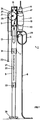
- Fig. 1 shows schematically in longitudinal view of an inventive device 1, comprising a tubular stator 5, at the upper end of a drill 3 is arranged for overhead work and for the production of boreholes in a concrete floor.
- the tubular stand 5 consists of a series of telescopically plug-in tube parts 7, which can be fixed for example by means of plug-in or latchable locking elements 31 and 33 in a certain length.
- the in Fig. 1 shown middle pipe segment with holes or notches 35 or provided on the opposite pipe side 37, in which holes fasteners 31 and 33 can be inserted.
- the arranged on the opposite side of the tube holes 37 are each offset in relation to the front side arranged perforations 35 arranged to allow the finest possible length adjustment of the tube or stator 5.
- a pipe top part or pipe head part 9 which telescopes over the uppermost pipe segment 7 is arranged, on which the drilling machine 3 is arranged.
- the bracket 41 of the drill 3 on this head part 9 will be described with reference to FIG Fig. 3 explained in more detail.
- This head part 9 is arranged by means of rollers 11 and 13 longitudinally displaceable on the uppermost tube segment 7 and connected thereto.
- this head part 9 terminal a stop 15, which is intended to limit, for example, the propulsion of a drill by abutting the head portion of a ceiling.
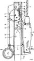
- the propulsion of the drill 3 and the head part 9 is now primarily under the action of a weight 17 which is disposed within the tube 5.
- the weight 17 is suspended on a belt 19, which is guided over a guide roller 21, which Deflection pulley on the top tube segment 7, with this firmly connected, is arranged.
- This deflection roller 21 extends through a slot-like opening in the uppermost tube segment 7 to the outside, and is protected in the outer region by a cover 24.
- the band 19 extends down the pulley 21 through the cover casing 24, and at the end opposite the weight 17 there is disposed on the belt 19 a handle or take-up reel 23, to which reference is made Fig. 3 to come back.
- the head part 9 relative to the uppermost tube segment 7 of the tube 5 is displaceable, this has laterally in the region of the guide roller 21 has a longitudinal slot which extends largely along the entire length of the head part 9.
- At least one gear 25 is provided in the axis of rotation of the deflection roller, laterally to the deflection roller 21, which engages in a toothed rack 27 which extends in the longitudinal direction of the slot in the interior of the head part 9.
- the device 1 If holes are to be made in a concrete pavement, the device 1 is placed at the desired location, and the drill is aligned with respect to the ceiling so that a hole can be made at the desired location.
- the electric drill 3 is powered by a first connection cable 4, a switch 29 and another connection cable 6 with power.
- the switch 29 the drill can be put into operation, whereupon by means of a handle 23, the lowering of the weight 17 can be triggered. On this release of the weight will be later, with reference to Fig. 3 . returned.
- the weight 17 moves downwards within the uppermost tube segment 7 and the deflection roller 21 is set in motion simultaneously via the belt 19.
- the gear 25 is set in motion at the same time, which engages in the rack 27.
- the head part 9 is driven upward and thus the drill 3, which is connected via a bracket 41 with the head part 9.
- This propulsion of the drill can either be stopped manually by the handle 23 is held, or by appropriate adjustment of the head-side stop 15 on the head part 9, which stop abuts, for example, on the ceiling.
- the weight 17 can be pulled up again within the uppermost tube segment 7 on the handle 23 until it, for example, in a stop, such as a rubber buffer 14, is present and can be locked. As a result, the drill 3 is simultaneously lowered again.
- a stop such as a rubber buffer 14
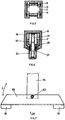
- FIG. 3 With reference to Fig. 3 is discussed some details, which can be preferably arranged in the inventive device. So are in Fig. 3 On the outer wall of the cover 24 notches 26 can be seen, in which notches a headband 41 of the holder 44 can be set latching. This makes it possible to arrange the holder 44 in different positions along the head part 9, for example, so as to set the drilling depth of a drill bit 2 of the drill 3. Further, it is possible to design the seat 45 of the holder 44 such that different makes of drills can be arranged in the holder. This seat 45 may also be designed such that, for example, a lateral displacement of the back of the drill from or to the top tube segment is possible to allow an accurate, vertical alignment of the drill with respect to the ceiling. The rear retaining element 43 finally the holder 44 may be formed such that this holder can be snap-engaged in the holding element 43 in order to quickly change the holder at any time, for example, again to arrange different types of drills on the head part 9.
- Another preferred embodiment feature is a locking device in the region of the guide roller 21, by means of which the weight 17 can be set in the starting position.
- This device comprises a tab 48, which extends on both sides of the deflection roller 21, in particular better in Fig. 4 recognizable.
- a cam 50 protruding on both sides is provided, which can be locked in a depression in a passage 49 in the front region of the lug 48. This locked position is in Figure 3 shown pulled out.
- handle 23 in FIG Fig. 3 refers, in which handle it may be, for example, a self-winding drum, by means of which the drawstring 19 automatically rolled up or when released again is rolled off.
- This drawstring 19 may be, for example, a chain-like element, a perforated belt, a perforated belt or an unperforated belt, on one side having knobs or notches, which engage in corresponding recesses in the periphery of the guide roller 21.
- the tension band 19 is firmly connected to the peripheral surface during the overrunning of the deflection roller 21, so that upon movement of the weight 17 downwards a rotational movement of the guide roller 21 is triggered to simultaneously drive the preferably each arranged on both sides gear 25.
- the head part 9 is driven upward by this gear 25 via the rack 27.
- the head part 9 is placed on the top segment 7 in such a way that during the drilling process resulting dust can not penetrate into the interior of the tube or the stator 5. This is achieved on the one hand in that the head part 9 is closed terminally by the stop 15, and on the other hand, by the walls of the lower, open end of the head part 9, the uppermost tube segment 7 outside surrounds downwardly open.
- Fig. 4 shows the head part 9 and the terminal tube element 7 in the direction of arrow A, according to Fig. 2 seen.
- the locking device for locking the guide roller 21 clearly visible, as well as protruding studs 51 in the peripheral periphery of the guide roller 21, for example, provided to intervene in perforations of the drawstring 19.
- Fig. 5 again shows the section along the line II Fig. 2 , representing the guide rollers 11, by means of which the head part 9 is guided on the head-side tube element 7.
- Fig. 6 shows the section along the line II-II Fig. 2 , in which section the guide roller 21 and the deflection roller to the outside overlapping housing 24 can be seen.
- nubs 51 which can engage in perforations of the tension band 19 in order to effect a rotational movement of the deflection roller 21 when the band 19 is moved.
- Fig. 6 also recognizable are the two laterally arranged each toothed wheels 25 which engage in corresponding toothed racks 27 of the tubular member 9 in order to move it in the longitudinal direction along the pipe segment 7.
- Fig. 6 shows Fig. 6 in that, in the region of the deflection roller 21, both the tubular element 7 and the head part 9 have a longitudinal section in the corresponding side wall.
- Fig. 7 shows a bottom part 39 of the tube 5, wherein the lowermost tube segment 7a is connected via a hinge 63 with a bottom plate 65.
- the tube 5 can be tilted in the direction of arrow B relative to the bottom plate 65, for example, if the ground is not horizontal, or if inclined bores are to be mounted in a concrete floor.
- FIG. 8 Finally shows a further embodiment of the bottom part 39 and an additional pipe part 67, which can be plugged over the bottom pipe part 7a and connected by means of locking pins 73 with this.
- This additional pipe part 67 is connected via a hinge 63 to a bottom plate 65, wherein in addition to the hinge 63, a support body 69 is provided, comprising several Auflageabstufonne 71. These different Auflageabstufonne 71, it is possible lower pipe parts, such as the pipe part 7a or to arrange the additional pipe part 67, with different diameters firmly on this support body 69.
- underside support body 61 which may be formed rounded, for example, to tilt the bottom plate 65 in the direction of arrow C can. If only a tilt in the direction of arrow B is desired, it is advantageous to provide these support body 61 in the four corners of the bottom plate 65.
- telescopically intermeshable tubular elements are made of a metal, as advantageously made of aluminum, or of a fiber-reinforced plastic material.
- material selection the same statements apply to the weight, the holding elements, etc., which are all made of metal or a correspondingly suitable plastic can be made.
- design features, such as lifting and re-attaching the head part 9, for example, to replace the weight should not be discussed further at this point, since this is a technical feature that is not directly essential to the invention in itself.
- a holder for arranging a tool is provided at the upper end of a tubular or stand-like element, for overhead working, which holder is operatively connected to a weight arranged on or in the tube such that upon movement of this weight due to Gravity down at the same time the bracket is driven away from the center of the pipe or against or over the upper end of the pipe to perform an operation with the tool can.
Landscapes
- Engineering & Computer Science (AREA)
- Mechanical Engineering (AREA)
- Processing Of Stones Or Stones Resemblance Materials (AREA)
Abstract
Bohrmaschinenhalter zum Automatischen bohren
von Montagelöcher in Betondecken.Drill machine holder for automatic drilling
of mounting holes in concrete ceilings.
Das Gerät besteht aus teleskopartig ineinander schiebbaren Rohren (5),
wovon über das oberste Rohrsegment (7) teleskopartig
ein Rohrkopfteil (9) auf Lagern (11) und (13) geführt übergestülpt ist.The device consists of telescopically telescoping tubes (5),
of which above the uppermost tube segment (7) telescopically
a pipe head part (9) on bearings (11) and (13) guided over.
Dieses Rohrkopfteil (9) wird mit einem Gewicht (17) das mittels einer Kette (19), über eine Umlenkrolle (21) nach oben bewegt.This pipe head part (9) is moved with a weight (17) by means of a chain (19), via a deflection roller (21) upwards.
Am Rohrkopfteil (9) wird eine Bohrmaschine (3) angebracht,
durch welche dann Montagelöcher in eine
Betondecke gebohrt werden können.

through which then mounting holes in one
Concrete pavement can be drilled.
Description
Die vorliegende Erfindung betrifft eine Vorrichtung zum Anordnen und den Vortrieb eines Werkzeuges bei Arbeiten über Kopf, beispielsweise an einer bzw. in eine Decke, ein höhenverstellbarer Halter für eine Bohrmaschine bei Arbeiten über Kopf sowie ein Verfahren zum Erzeugen von Bohrlöchern in einer Betondecke.The present invention relates to a device for arranging and propelling a tool when working overhead, for example on a ceiling, a height-adjustable holder for a drill when working overhead and a method for producing boreholes in a concrete pavement.
Für das Anordnen von Werkzeugen, Maschinen und dgl., wie insbesondere von Bohrmaschinen für Arbeiten über Kopf, beispielsweise im Bereich einer Decke sind eine Reihe von Vorrichtungen bekannt.For the arrangement of tools, machines and the like, in particular of drills for working overhead, for example in the area of a ceiling, a number of devices are known.
So beschreibt beispielsweise die
In der
Die
Alle vorgeschlagenen Lösungen haben den Nachteil, dass während dem Bohrvorgang durch eine Bedienungsperson bzw. durch einen Arbeiter gleichzeitig ein Mechanismus betätigt werden muss, um die Bohrmaschine voranzutreiben. Speziell bei Arbeiten über Kopf ist volle Konzentration erforderlich, welche dadurch aber gestört ist, womit die Arbeitsausführung ungenau wird. Zudem sind die beschriebenen Arbeitsweisen relativ kraftaufwendig, so dass rasch mit der Ermüdung des bedienenden Arbeiters zu rechnen ist.All proposed solutions have the disadvantage that during the drilling process by an operator or by a worker at the same time a mechanism must be operated to to push the drill. Especially when working overhead, full concentration is required, which is thereby disturbed, which makes the work inaccurate. In addition, the procedures described are relatively power consuming, so that can be expected quickly from the fatigue of the serving worker.
Es ist daher eine Aufgabe der vorliegenden Erfindung, eine Vorrichtung zu schaffen, welche ein einfaches Arbeiten über Kopf ermöglicht ohne die eingangs erwähnten, unerwünschten, manuellen Arbeitsschritte.It is therefore an object of the present invention to provide a device which allows easy overhead work without the aforementioned undesirable manual operations.
Erfindungsgemäss wird die gestellte Aufgabe mittels einer Vorrichtung gemäss dem Wortlaut nach Anspruch 1 gelöst.According to the invention the object is achieved by means of a device according to the wording of claim 1.
Vorgeschlagen wird, dass an einem in seiner Längsausdehnung veränderbaren, rohrförmig bzw. ständerartigen Element an einem Endbereich eine Halterung für das Werkzeug vorgesehen ist, welche Halterung in Längsrichtung verschieblich mit dem Rohr bzw. dem Ständer verbunden ist. Diese Halterung am rohrförmigen bzw. ständerartigen Element ist mit einem verschiebbaren Gewicht derart gekoppelt, dass bei Bewegung des Gewichtes infolge Gravitation die Halterung vom Rohr bzw. Ständer-Mittelpunkt weggetrieben wird, d.h. die Halterung wird durch die gravitationsbedingte Bewegung des Gewichtes gegen das obere Ende des Rohres bzw. des Ständers oder über dieses Ende hinaus, beispielsweise gegen eine Decke, getrieben.It is proposed that a holder for the tool is provided on an end region which can be changed in its longitudinal extent, tubular or stator-like element, which holder is displaceably connected in the longitudinal direction to the tube or the stator. This mount on the tubular member is coupled to a slidable weight such that upon movement of the weight due to gravity, the mount is expelled from the pipe or stud center, i. the holder is driven by the gravitational movement of the weight against the upper end of the tube or of the stand or beyond this end, for example against a ceiling.
Bevorzugte Ausführungsvarianten der erfindungsgemäss definierten Vorrichtung sind in den abhängigen Ansprüchen 2 - 13 charakterisiert.Preferred embodiments of the device defined according to the invention are characterized in the dependent claims 2-13.
Die erfindungsgemäss beschriebene Vorrichtung eignet sich insbesondere für das Anordnen und das Arbeiten mit einer Bohrmaschine bei Arbeiten über Kopf, beispielsweise beim Anbringen von Löchern in einer Betondecke.The device described in the invention is particularly suitable for arranging and working with a drill when working overhead, for example, when mounting holes in a concrete pavement.
Die Erfindung wird nun beispielsweise und unter Bezug auf die beigefügten Figuren näher erläutert.The invention will now be explained in more detail by way of example and with reference to the accompanying drawings.
Dabei zeigen:
- Fig. 1
- schematisch im Längsschnitt eine erfindungsgemässe Vorrichtung für das Arbeiten mit einer Bohrmaschine über Kopf zum Anbringen von Löchern in einer Betondecke,
- Fig. 2
- das obere Ende der Vorrichtung von
Fig. 1 in vergrösserter Darstellung, zeigend schematisch den Antrieb für das Bewegen der Bohrmaschine (nicht dargestellt) in die Decke, - Fig. 3
- wiederum das obere Ende der erfindungsgemässen Vorrichtung, zeigend die Befestigung der Halterung für die Bohrmaschine,
- Fig. 4
- darstellend das obere Ende der Vorrichtung, gesehen in Pfeilrichtung A in
Fig. 2 , - Fig. 5
- den Schnitt entlang der Linie I-I aus
Fig. 2 , - Fig. 6
- den Schnitt entlang der Linie II-II aus
Fig. 2 , - Fig. 7
- das Bodenteil der Vorrichtung gemäss
Fig. 1 , und - Fig. 8
- eine weitere Ausführungsvariante des Bodenteils der Vorrichtung aus
Fig. 1 .
- Fig. 1
- 1 is a schematic longitudinal sectional view of an apparatus according to the invention for working with a drill head over the head for mounting holes in a concrete floor;
- Fig. 2
- the upper end of the device of
Fig. 1 in an enlarged view, schematically shows the drive for moving the drill (not shown) in the ceiling, - Fig. 3
- again the upper end of the device according to the invention, showing the fastening of the holder for the drilling machine,
- Fig. 4
- representing the upper end of the device, seen in the direction of arrow A in FIG
Fig. 2 . - Fig. 5
- the section along the line II
Fig. 2 . - Fig. 6
- the section along the line II-II
Fig. 2 . - Fig. 7
- the bottom part of the device according to
Fig. 1 , and - Fig. 8
- a further embodiment of the bottom part of the device
Fig. 1 ,
Am oberen Rohr ende ist ein das oberste Rohrsegment 7 teleskopartig überhüllendes Rohrendteil oder Rohrkopfteil 9 angeordnet, an welchem die Bohrmaschine 3 angeordnet ist. Die Halterung 41 der Bohrmaschine 3 an diesem Kopfteil 9 wird unter Bezug auf
Der Vortrieb der Bohrmaschine 3 bzw. des Kopfteiles 9 erfolgt nun primär unter Einwirkung eines Gewichtes 17, welches innerhalb des Rohres 5 angeordnet ist Das Gewicht 17 hängt an einem Band 19, welches über eine Umlenkrolle 21 geführt ist, welche Umlenkrolle am obersten Rohrsegment 7, mit diesem festverbunden, angeordnet ist. Diese Umlenkrolle 21 erstreckt sich durch eine schlitzartige Öffnung im obersten Rohrsegment 7 nach aussen, und ist im äusseren Bereich durch eine Abdeckung 24 geschützt. Das Band 19 erstreckt sich über die Umlenkrolle 21 durch das Abdeckgehäuse 24 nach unten, und an dem, dem Gewicht 17 entgegengesetzten Ende ist am Band 19 ein Haltegriff oder eine Aufwickelspule 23 angeordnet, auf welche unter Bezug auf
Damit das Kopfteil 9 gegenüber dem obersten Rohrsegment 7 des Rohres 5 verschiebbar ist, weist dieses seitlich im Bereich der Umlenkrolle 21 einen Längsschlitz auf, welcher sich weitgehendst entlang der ganzen Länge des Kopfteiles 9 erstreckt.Thus, the
Schlussendlich ist in der Drehachse der Umlenkrolle, seitlich zur Umlenkrolle 21 mindestens ein Zahnrad 25 vorgesehen, welches in eine Zahnstange 27 eingreift, welche sich längsseitlich des Schlitzes im Innern des Kopfteils 9 erstreckt.Finally, at least one
Unter Bezug der
Dass dieser Bohrvorgang möglichst gleichmässig und ruhig vor sich geht wird dadurch sichergestellt, dass einerseits das Gewicht 17 mittels seitlichen Rollen oder Pufferelementen 18 innerhalb des obersten Rohrsegmentes 7 einwandfrei geführt ist und andererseits, dass das Band 19 durch Rollen 16 sowie Führungselementen 20 weitgehendst schwingungsfrei zur Umlenkrolle 21 geführt wird. Es ist auch möglich in der Umlenkrolle 21 einen Bremsmechanismus vorzusehen, derart, dass das Gewicht 19 nur mit einer sehr reduzierten Geschwindigkeit nach unten bewegt wird, was den grossen Vorteil mit sich bringt, dass der Bohrvortrieb der Bohrmaschine 3 gleichmässig und immer mit gleicher Vortriebskraft erfolgt.That this drilling process is as even and quiet as possible is ensured by the fact that on the one hand the
Sobald der Bohrvorgang beendet ist kann am Handgriff 23 das Gewicht 17 innerhalb des obersten Rohrsegmentes 7 wieder nach oben gezogen werden, bis es beispielsweise in einem Anschlag, wie einem Gummipuffer 14, ansteht und arretiert werden kann. Dadurch wird die Bohrmaschine 3 gleichzeitig wieder abgesenkt.Once the drilling process is completed, the
Es ist nun möglich den Schalter 29 derart auszubilden, dass einerseits der Strom erst von Kabel 6 zu Kabel 4 fliesst, wenn der Vortrieb des Kopfteiles 9 ausgelöst worden ist und andererseits der Strom wieder unterbrochen wird, wenn das Kopfteil nach erfolgtem Bohrvorgang wieder zurückgezogen wird. Selbstverständlich ist es auch möglich, durch das Anbringen eines weiteren Schalters am Anschlag 15 die Stromzufuhr bereits zu unterbrechen, wenn der Anschlag 15 an der Decke ansteht.It is now possible to form the
Unter Bezug auf
Ein weiteres bevorzugtes Ausführungsmerkmal bildet eine Arretiereinrichtung im Bereich der Umlenkrolle 21, mittels welcher das Gewicht 17 in Ausgangslage festgelegt werden kann. Diese Einrichtung umfasst eine Lasche 48, welche sich je beidseits der Umlenkrolle 21 erstreckt, wie insbesondere besser in
Weiter sei auf die besondere Ausgestaltung des Griffes 23 in
Schlussendlich sei darauf hingewiesen, dass das Kopfteil 9 auf das oberste Segment 7 aufgesetzt ist und zwar derart, dass beim Bohrvorgang entstehender Staub nicht in das Innere des Rohres bzw. des Ständers 5 eindringen kann. Dies wird einerseits dadurch erreicht, dass das Kopfteil 9 endständig durch den Anschlag 15 verschlossen ist, und andererseits, indem die Wandungen des unteren, offenen Endes des Kopfteiles 9 das oberste Rohrsegment 7 aussen nach unten offen umgreift. selbstverständlich ist es möglich, im Bereich der unteren Öffnung des Kopfteiles 9 weitere Massnahmen vorzusehen, damit kein Staub zwischen die Wandungen des Kopfteils 9 und des obersten Rohrsegmentes 7 eindringen kann.Finally, it should be noted that the
Wiederum erkennbar sind an der Unterseite Auflagekörper 61, welche beispielsweise abgerundet ausgebildet sein können, um die Bodenplatte 65 in Pfeilrichtung C kippen zu können. Falls nur ein Kippen in Pfeilrichtung B erwünscht ist, ist es vorteilhaft diese Auflagekörper 61 in den vier Ecken der Bodenplatte 65 vorzusehen.Again visible on the
Bei den in den
Erfindungswesentlich ist, dass am oberen Ende eines rohrförmigen oder ständerartigen Elementes, für das Arbeiten über Kopf, eine Halterung für das Anordnen eines Werkzeuges vorgesehen ist, welche Halterung mit einem am oder im Rohr angeordneten Gewicht derart wirkverbunden ist, dass bei Bewegen dieses Gewichtes infolge von Gravitation nach unten gleichzeitig die Halterung vom Rohrmittelpunkt weg bzw. gegen oder über das obere Rohrende hinausgetrieben wird, um mit dem Werkzeug eine Operation ausführen zu können.It is essential to the invention that a holder for arranging a tool is provided at the upper end of a tubular or stand-like element, for overhead working, which holder is operatively connected to a weight arranged on or in the tube such that upon movement of this weight due to Gravity down at the same time the bracket is driven away from the center of the pipe or against or over the upper end of the pipe to perform an operation with the tool can.
Claims (15)
Rohr bzw. Ständer verbunden ist, und welche Halterung mit einem verschiebbaren Gewicht derart gekoppelt ist, dass bei Bewegung des Gewichtes infolge Gravitation die Halterung vom Rohr- oder Ständermittelpunkt weggetrieben wird.Device for arranging and for the propulsion of a tool when working overhead, for example on or in a concrete floor, characterized in that on a variable in its longitudinal extent, tubular or stand-like element at one end portion a holder for the tool is provided which displaceable in the longitudinal direction with the
Tube or stand is connected, and which holder is coupled to a sliding weight such that upon movement of the weight due to gravity, the holder is driven away from the tube or stator center.
drehbare Umlenkrolle durch ein Band derart miteinander wirkverbunden sind, dass bei Bewegen des Gewichtes infolge Gravitation
die Halterung vom Rohr- oder Ständermittelpunkt weggetrieben wird.Device, in particular according to claim 1, characterized in that the weight and the holder over a free
rotatable deflection roller are operatively connected to each other by a band such that when moving the weight due to gravity
the bracket is driven away from the pipe or stator center.
das Band mit den Lochungen bzw. Einkerbungen im Umfang der Umlenkrolle eingreifend über die Rolle geführt ist und diese bei Verschieben des Gewichtes in Rotation versetzt, welche Rotationsbewegung die Verschiebung der Halterung auslöst.Device, in particular according to one of claims 1 or 2, characterized in that the weight is slidably guided within the tube and is operatively connected via a fixedly connected to the tube pulley by means of a perforations or notches having band with the holder
the band with the perforations or indentations in the circumference of the deflection roller is guided over the roller engaging and this set upon displacement of the weight in rotation, which rotational movement triggers the displacement of the holder.
ist, derart, dass bei Bewegen des Gewichtes infolge Schwerkraft
die Halterung um eine wesentlich kleinere Wegstrecke vom RohrMittelpunkt wegbewegt wird, als die vom Gewicht zurückgelegte Strecke.Device, in particular according to claim 3, characterized in that provided on the deflection roller a translation
is such that when moving the weight due to gravity
the bracket is moved away from the center of the tube by a much smaller distance than the distance traveled by the weight.
an seiner inneren Wandung eine längsausgedehnte Gewinde- oder Zahnstange aufweist, in welche das Zahnrad eingreift.Device, in particular according to one of claims 2 to 4, characterized in that concentrically arranged on the guide roller at least one gear, with a substantially smaller diameter than the guide roller and that the holder laterally on a mounted on the pipe end and this cross-over, one-sided closed , Telescopically displaceable Rohrendteil or headboard is arranged, which
has on its inner wall a longitudinally extended threaded or rack into which engages the gear.
der Halterung und/oder im Bereich der Führung des Gewichtes ein Endanschlag vorgesehen ist, um den Vortrieb des Werkzeuges nach einer vorbestimmten Weglänge zu begrenzen.Device, in particular according to claim 5, characterized in that the displaceable Rohrendteil or head part, to
the holder and / or in the region of the guide of the weight an end stop is provided to limit the propulsion of the tool after a predetermined path length.
dadurch gekennzeichnet, dass das Gewicht in seiner angehobenen Ausgangslage festlegbar bzw. arretierbar ist.Device, in particular according to one of claims 1 to 7,
characterized in that the weight in its raised starting position can be fixed or locked.
dadurch gekennzeichnet, dass an der Umlenkrolle einrastbare Mittel vorgesehen sind zum Festlegen bzw. Arretieren des Gewichtes in der Ausgangslage, welche Einrastmittel entriegelbar
sind, beispielsweise mittels Anlegen eines Zuges auf das Band in die das Gewicht nach oben ziehende Richtung.Device, in particular according to one of claims 2 to 8,
characterized in that provided on the deflection roller latching means are provided for fixing or locking the weight in the starting position, which Einrastmittel unlocked
are, for example, by applying a train on the tape in the direction of the weight pulling upwards.
der einzelnen Elemente Verriegelungs- bzw. Festlegemittel vorgesehen sind, um die Elemente in einer vorbestimmten Länge des Rohres bzw. des Ständers fest miteinander zu verbinden.Device, in particular according to one of claims 1 to 9, characterized in that the tube or the stator consists of several elements, telescopically formed one inside the other and in the region of the respective compounds
the individual elements locking or fixing means are provided to connect the elements in a predetermined length of the tube or the stator firmly together.
in eine Richtung kippbar bzw. schwenkbar über eine Achse verbunden ist, und dass optional an der Unterseite des Bodenteils abgerundete Auflageflächen vorgesehen sind, derart,
dass das Bodenteil und damit verbunden das Rohr bzw. der Ständer in mindestens eine weitere Richtung kippbar ist.Device, in particular according to one of claims 1 to 10, characterized in that the tube or the stator has a bottom part, with which the tube or the stand at least
in a direction tiltable or pivotally connected via an axis, and that optionally provided on the underside of the bottom part of rounded bearing surfaces, in such a way
the bottom part and, connected thereto, the tube or the stand can be tilted in at least one further direction.
mit dem Rohrendteil bzw. Kopfteil verbunden ist, und in
verschiedenen, vorzugsweise einem vorgegebenen Raster entsprechenden Positionen fest mit dem Rohrendteil verbindbar ist.Device, in particular according to one of claims 5 to 11, characterized in that the holder is longitudinally displaceable
is connected to the Rohrendteil or headboard, and in
different, preferably a predetermined grid corresponding positions fixed to the pipe end part is connectable.
vorgesehen ist, welches zwischen Rohr bzw. Ständer und
dem Bodenteil angeordnet werden kann, derart, dass es auf dem
unteren Ende des Rohres aufschiebbar und mit diesem fest verbindbar
ist, um das Rohr bzw. den Ständer weiter zu verlängern.Device, in particular according to one of claims 11 or 12, characterized in that at least one further tubular element
is provided, which between pipe or stand and
the bottom part can be arranged so that it on the
pushed on the lower end of the tube and firmly connected with this
is to further extend the tube or the stand.
Bohrmaschine für Arbeiten über Kopf, insbesondere für das Erstellen
von Bohrlöchern in einer Betondecke, dadurch gekennzeichnet,
dass es sich um eine Vorrichtung nach einem der Ansprüche
1 bis 13 handelt.Height adjustable tool holder for placing a
Drilling machine for working overhead, in particular for creating
of boreholes in a concrete pavement, characterized
that it is a device according to one of the claims
1 to 13 acts.
gekennzeichnet, dass die für das Erstellen notwendige
Bohrmaschine endständig in einer Halterung an einem rohrförmigen
bzw. ständerartigen Element angeordnet wird, welche Halterung längsverschieblich mit dem Rohr bzw. dem Ständer verbunden
ist, und dass am bzw. im Rohr ein Gewicht infolge Gravitation
nach unten bewegt wird, welches Gewicht über eine Umlenkrolle
mit der Halterung wirkverbunden ist, wobei durch die nach unten
erfolgte Bewegung des Gewichtes die Halterung zusammen mit der
Bohrmaschine nach oben bzw. gegen die Decke getrieben wird, um
so ein Bohrloch in der Betondecke zu erzeugen.Method for producing boreholes in a concrete pavement by means of a device according to one of claims 1 to 13, characterized
marked that necessary for the creation
Drill terminal in a holder on a tubular
or stand-like element is arranged, which holder is longitudinally displaceable connected to the tube or the stator
is, and that on or in the tube a weight due to gravity
is moved down, which weight over a pulley
is operatively connected to the bracket, passing through the down
movement of the weight took place the holder together with the
Drill is driven upwards or against the ceiling to
to create such a borehole in the concrete pavement.
Priority Applications (1)
| Application Number | Priority Date | Filing Date | Title |
|---|---|---|---|
| EP17405011.2A EP3421186A1 (en) | 2017-06-26 | 2017-06-26 | Drill holder for automatic drilling of mounting holes in concrete ceilings |
Applications Claiming Priority (1)
| Application Number | Priority Date | Filing Date | Title |
|---|---|---|---|
| EP17405011.2A EP3421186A1 (en) | 2017-06-26 | 2017-06-26 | Drill holder for automatic drilling of mounting holes in concrete ceilings |
Publications (1)
| Publication Number | Publication Date |
|---|---|
| EP3421186A1 true EP3421186A1 (en) | 2019-01-02 |
Family
ID=59296803
Family Applications (1)
| Application Number | Title | Priority Date | Filing Date |
|---|---|---|---|
| EP17405011.2A Withdrawn EP3421186A1 (en) | 2017-06-26 | 2017-06-26 | Drill holder for automatic drilling of mounting holes in concrete ceilings |
Country Status (1)
| Country | Link |
|---|---|
| EP (1) | EP3421186A1 (en) |
Citations (10)
| Publication number | Priority date | Publication date | Assignee | Title |
|---|---|---|---|---|
| US2571862A (en) * | 1948-04-15 | 1951-10-16 | Joy L Glenn | Adjustable support for hammer drills |
| GB823442A (en) * | 1957-02-27 | 1959-11-11 | Internat Staple And Machine Co | Standard for automatic stapling machine |
| JPS5937006A (en) * | 1982-08-17 | 1984-02-29 | Toshiba Corp | Turning type drilling machine |
| LU86169A1 (en) * | 1985-11-20 | 1986-03-24 | Armand Lang | DRILL STAND WITH FEEDING DEVICE FOR HAND DRILLING MACHINE |
| DE4017532A1 (en) * | 1990-05-31 | 1991-12-05 | Robert Stadler | Frame supporting heavy hand-held tool - has uprights which form guide for slide holding tool |
| DE4216710A1 (en) | 1991-05-20 | 1992-11-26 | T Mi Mikko Aho | Height adjustable work-head holding assembly - has sliding part with integral linear gear part which may be in form of chain |
| US5295620A (en) | 1992-10-13 | 1994-03-22 | Cousineau B Robert | Extendable arm for power and impact tools |
| US5322397A (en) | 1993-10-04 | 1994-06-21 | Spear James C | Apparatus for supporting a drill in an elevated position |
| DE19501663A1 (en) | 1995-01-20 | 1996-07-25 | Werner Johann Krammel | Height adjustable tool holder esp. for electric tools used in overhead work |
| WO2013154480A1 (en) * | 2012-04-13 | 2013-10-17 | Atlas Copco Industrial Technique Ab | Failure safety device in a tool holding arm |
-
2017
- 2017-06-26 EP EP17405011.2A patent/EP3421186A1/en not_active Withdrawn
Patent Citations (10)
| Publication number | Priority date | Publication date | Assignee | Title |
|---|---|---|---|---|
| US2571862A (en) * | 1948-04-15 | 1951-10-16 | Joy L Glenn | Adjustable support for hammer drills |
| GB823442A (en) * | 1957-02-27 | 1959-11-11 | Internat Staple And Machine Co | Standard for automatic stapling machine |
| JPS5937006A (en) * | 1982-08-17 | 1984-02-29 | Toshiba Corp | Turning type drilling machine |
| LU86169A1 (en) * | 1985-11-20 | 1986-03-24 | Armand Lang | DRILL STAND WITH FEEDING DEVICE FOR HAND DRILLING MACHINE |
| DE4017532A1 (en) * | 1990-05-31 | 1991-12-05 | Robert Stadler | Frame supporting heavy hand-held tool - has uprights which form guide for slide holding tool |
| DE4216710A1 (en) | 1991-05-20 | 1992-11-26 | T Mi Mikko Aho | Height adjustable work-head holding assembly - has sliding part with integral linear gear part which may be in form of chain |
| US5295620A (en) | 1992-10-13 | 1994-03-22 | Cousineau B Robert | Extendable arm for power and impact tools |
| US5322397A (en) | 1993-10-04 | 1994-06-21 | Spear James C | Apparatus for supporting a drill in an elevated position |
| DE19501663A1 (en) | 1995-01-20 | 1996-07-25 | Werner Johann Krammel | Height adjustable tool holder esp. for electric tools used in overhead work |
| WO2013154480A1 (en) * | 2012-04-13 | 2013-10-17 | Atlas Copco Industrial Technique Ab | Failure safety device in a tool holding arm |
Similar Documents
| Publication | Publication Date | Title |
|---|---|---|
| DE60111852T2 (en) | SELF-LIFTING PLATFORM DEVICE | |
| EP2057328B1 (en) | Arrangement for conveying concrete with a height-adjustable concrete-distributing mast | |
| DE1228040B (en) | Crane whose column is built up from a plurality of mast elements | |
| EP1198024A1 (en) | Antenna mast | |
| DE19512070C2 (en) | Drill | |
| EP2534310A2 (en) | Method for producing material columns and vibrating device having a reciprocating unit | |
| DE3446900C2 (en) | Method and device for cleaning the helix of an auger | |
| DE2815149C3 (en) | Method and device for breaking up a shaft by drilling upwards from a solid | |
| DE102008044352B4 (en) | Mobile drilling device for creating multiple holes in a component | |
| EP3421186A1 (en) | Drill holder for automatic drilling of mounting holes in concrete ceilings | |
| DE19501663A1 (en) | Height adjustable tool holder esp. for electric tools used in overhead work | |
| DE202007004424U1 (en) | Mechanical components e.g. bearing, pulling tool, has adjusting unit mounted at assembly for vertical adjustment of angle of inclination of housing so that large-piece mechanical components are taken apart | |
| DE3729561C2 (en) | ||
| DE102011100691A1 (en) | Drilling apparatus and method for operating a drilling rig | |
| DE19512109A1 (en) | Drilling rig mounted on tractor unit with compact drive head arrangement | |
| EP2025859A1 (en) | Deep drilling device and method for mounting a deep drilling device | |
| WO2002033784A1 (en) | Antenna mast | |
| EP3081699B1 (en) | Civil engineering device and method for creating a foundation element in the ground | |
| EP4051472B1 (en) | Formwork device | |
| EP3708764B1 (en) | Drilling device | |
| DE202008000325U1 (en) | Amusement device for fairs, amusement parks or the like | |
| DE102016118132B4 (en) | Device and method for installing a pipe in the subsoil of a body of water | |
| DE451727C (en) | Deep drilling device working according to the rotary drilling system and secured in the borehole against rotation by clamping jaws | |
| DE10215870B4 (en) | Self-climbing platform device for fireplaces | |
| DE10163390B4 (en) | Schlitzwandfräsvorrichtung and suspension slides for this purpose |
Legal Events
| Date | Code | Title | Description |
|---|---|---|---|
| STAA | Information on the status of an ep patent application or granted ep patent |
Free format text: STATUS: EXAMINATION IS IN PROGRESS |
|
| PUAI | Public reference made under article 153(3) epc to a published international application that has entered the european phase |
Free format text: ORIGINAL CODE: 0009012 |
|
| STAA | Information on the status of an ep patent application or granted ep patent |
Free format text: STATUS: EXAMINATION IS IN PROGRESS |
|
| 17P | Request for examination filed |
Effective date: 20171121 |
|
| AK | Designated contracting states |
Kind code of ref document: A1 Designated state(s): AL AT BE BG CH CY CZ DE DK EE ES FI FR GB GR HR HU IE IS IT LI LT LU LV MC MK MT NL NO PL PT RO RS SE SI SK SM TR |
|
| AX | Request for extension of the european patent |
Extension state: BA ME |
|
| 19U | Interruption of proceedings before grant |
Effective date: 20190215 |
|
| 19W | Proceedings resumed before grant after interruption of proceedings |
Effective date: 20211001 |
|
| RAP3 | Party data changed (applicant data changed or rights of an application transferred) |
Owner name: EUGSTER, SAMUEL HANS Owner name: EUGSTER, IDA REGINA |
|
| RIN1 | Information on inventor provided before grant (corrected) |
Inventor name: EUGSTER, SAMUEL |
|
| STAA | Information on the status of an ep patent application or granted ep patent |
Free format text: STATUS: THE APPLICATION HAS BEEN WITHDRAWN |
|
| 18W | Application withdrawn |
Effective date: 20211104 |