EP3421146B1 - Combined powder cleaning gun for an automatic powder cleaning system for mixed-line hub bolt holes - Google Patents
Combined powder cleaning gun for an automatic powder cleaning system for mixed-line hub bolt holes Download PDFInfo
- Publication number
- EP3421146B1 EP3421146B1 EP18179552.7A EP18179552A EP3421146B1 EP 3421146 B1 EP3421146 B1 EP 3421146B1 EP 18179552 A EP18179552 A EP 18179552A EP 3421146 B1 EP3421146 B1 EP 3421146B1
- Authority
- EP
- European Patent Office
- Prior art keywords
- powder
- combined unit
- section
- combined
- powder cleaning
- Prior art date
- Legal status (The legal status is an assumption and is not a legal conclusion. Google has not performed a legal analysis and makes no representation as to the accuracy of the status listed.)
- Active
Links
Images
Classifications
-
- B—PERFORMING OPERATIONS; TRANSPORTING
- B08—CLEANING
- B08B—CLEANING IN GENERAL; PREVENTION OF FOULING IN GENERAL
- B08B7/00—Cleaning by methods not provided for in a single other subclass or a single group in this subclass
- B08B7/0028—Cleaning by methods not provided for in a single other subclass or a single group in this subclass by adhesive surfaces
-
- B—PERFORMING OPERATIONS; TRANSPORTING
- B08—CLEANING
- B08B—CLEANING IN GENERAL; PREVENTION OF FOULING IN GENERAL
- B08B5/00—Cleaning by methods involving the use of air flow or gas flow
- B08B5/02—Cleaning by the force of jets, e.g. blowing-out cavities
-
- B—PERFORMING OPERATIONS; TRANSPORTING
- B08—CLEANING
- B08B—CLEANING IN GENERAL; PREVENTION OF FOULING IN GENERAL
- B08B15/00—Preventing escape of dirt or fumes from the area where they are produced; Collecting or removing dirt or fumes from that area
- B08B15/04—Preventing escape of dirt or fumes from the area where they are produced; Collecting or removing dirt or fumes from that area from a small area, e.g. a tool
-
- B—PERFORMING OPERATIONS; TRANSPORTING
- B08—CLEANING
- B08B—CLEANING IN GENERAL; PREVENTION OF FOULING IN GENERAL
- B08B5/00—Cleaning by methods involving the use of air flow or gas flow
- B08B5/04—Cleaning by suction, with or without auxiliary action
-
- B—PERFORMING OPERATIONS; TRANSPORTING
- B08—CLEANING
- B08B—CLEANING IN GENERAL; PREVENTION OF FOULING IN GENERAL
- B08B9/00—Cleaning hollow articles by methods or apparatus specially adapted thereto
-
- Y—GENERAL TAGGING OF NEW TECHNOLOGICAL DEVELOPMENTS; GENERAL TAGGING OF CROSS-SECTIONAL TECHNOLOGIES SPANNING OVER SEVERAL SECTIONS OF THE IPC; TECHNICAL SUBJECTS COVERED BY FORMER USPC CROSS-REFERENCE ART COLLECTIONS [XRACs] AND DIGESTS
- Y02—TECHNOLOGIES OR APPLICATIONS FOR MITIGATION OR ADAPTATION AGAINST CLIMATE CHANGE
- Y02P—CLIMATE CHANGE MITIGATION TECHNOLOGIES IN THE PRODUCTION OR PROCESSING OF GOODS
- Y02P70/00—Climate change mitigation technologies in the production process for final industrial or consumer products
- Y02P70/10—Greenhouse gas [GHG] capture, material saving, heat recovery or other energy efficient measures, e.g. motor control, characterised by manufacturing processes, e.g. for rolling metal or metal working
Definitions
- the present invention relates to a combined powder cleaning gun, and an automatic powder cleaning system for mixed-line hub bolt holes, and relates to the technical field of hub coating.
- An automobile wheel bolt hole, a ball socket and a platform pertain to the mating feature of a fastening bolt and a hub, and involve the safety, so paint films are not allowed.
- small plug or ball protectors are generally adopted, and the sizes of the protectors corresponding to different wheels are different, so a large number of different protectors are needed; and paint drop treatment must be performed after the protectors are used for a period of time, and many hazardous wastes may be produced, resulting in noncompliance with the requirements of enterprises for green, lean and automatic development.
- EP 1 413 367 A2 discloses a suction device.
- the suction device has a conveying system moving the automobile wheel past an electronic camera, for detecting the axial and angular position of the wheel, for controlling a movement device for a suction head with a number of suction jets, used for removal of powder-coated paint from precise areas of the wheel.
- the present invention provides a combined powder cleaning gun in accordance with claim 1, and, in accordance with claim 3, an automatic powder cleaning system comprising the combined powder cleaning gun, which are used for replacing small plug protection with automatic powder absorption in the hub powder spraying production process, thereby avoiding customization and storage of a large number of protective small plugs as well as massive pollution caused by paint drop treatment.
- the present invention adopts the following technical solution: an automatic powder cleaning system for mixed-line hub bolt holes, characterized in that the powder cleaning system includes a control system, a recognition system, a powder cleaning robot, a gun storage and accessory device, wherein the recognition system and the powder cleaning robot are connected with the control system by adopting electroweak system, a plurality of combined powder spraying guns according to the present invention are arranged in the gun storage, a quick disassembly fixture is arranged at the end of the powder cleaning robot.
- the process flow of the powder cleaning system includes: storing a powder cleaning program, recognizing a wheel type, entering a powder room and spraying powder, entering a powder cleaning station, calling the powder cleaning program, replacing a gun by the robot, cleaning powder, and completing powder cleaning.
- the recognition system is a visual recognition system, and is used for recognizing and inputting all wheel type image information before production and editing wheel type code information, wherein the wheel type code information corresponds one-to-one to images.
- the recognition system refers to a bar code or two-dimensional code set at a specific position of a hub and a code reading device arranged at a wheel type recognition station, wherein the code reading device is connected with the control system by adopting electroweak system.
- the combined powder cleaning gun includes a combined gun body and a gun barrel, the combined gun body including front and rear combined units, the lateral surface of each combined unit includes a front splicing section and a rear powder absorbing section, the diameter of the powder absorbing section is greater than that of the splicing section, a powder absorbing through hole is formed in the center of each combined unit, and the powder absorbing section of each combined unit is provided with a powder absorbing hole; the diameters of the splicing section and the powder absorbing section of the rear combined unit are respectively greater than those of the splicing section and the powder absorbing section of the front combined unit, and a connecting device is arranged at each of the front and rear ends of each combined unit; the gun barrel includes a central gun barrel and a ball socket and platform gun barrel, the tail of the central gun barrel is connected with the splicing section of the front combined unit, the tail of the ball socket and platform
- the powder absorbing hole of the powder absorbing section is perpendicular to the axis of the combined unit, and is intersected with the powder absorbing through hole.
- the automatic powder cleaning system for mixed-line hub bolt holes and the combined powder cleaning gun are used for an automatic mixed-line powder spraying process of a hub via robot programming and hub recognition technologies.
- the robot automatically and quickly selects different types of combined powder cleaning guns; after powder spraying under the condition that the hub is not provided with protectors, the head of the central gun barrel absorbs powder at the bolt hole, and the ball socket and platform gun barrel absorbs powder at the ball socket and platform of the bolt hole; protective small plugs for bolt holes are replaced by the powder cleaning gun, so that a large number of small plugs are avoided, the production cost is reduced, and the environmental pollution caused by paint drop of the small plugs is prevented; and the absorbed powder can be reused, so that the automatic powder cleaning system and the combined powder cleaning gun conform to the green, lean and automatic development process of modern enterprises.
- An automatic powder cleaning system for mixed-line hub bolt holes includes a control system, a recognition system, a powder cleaning robot, a gun storage and accessory device, wherein the recognition system and the powder cleaning robot are connected with the control system by adopting electroweak system, a plurality of combined powder spraying guns are arranged in the gun storage, a quick disassembly fixture is arranged at the end of the powder cleaning robot, and the process flow of the powder cleaning system includes: storing a powder cleaning program, recognizing a wheel type, entering a powder room and spraying powder, entering a powder cleaning station, calling the powder cleaning program, replacing a gun for the robot, cleaning powder, and completing powder cleaning.
- a combined powder cleaning gun for the automatic powder cleaning system for mixed-line hub bolt holes includes, as shown in Figs. 1-6 , includes a combined gun body and a gun barrel.
- the combined gun body includes a front combined unit 3 and a rear combined unit 5.
- the lateral surface of the front combined unit 3 includes a front first splicing section 302 and a rear first powder absorbing section 305.
- the rear combined unit 5 includes a front second splicing section 502 and a rear second powder absorbing section 505.
- the diameters of the first powder absorbing section 305 and the second powder absorbing section 505 are respectively greater than those of the first splicing section 302 and the second splicing section 502.
- a first powder absorbing through hole 307 and a second powder absorbing through hole 507 are respectively formed in the centers of the front combined unit 3 and the rear combined unit 5.
- the first powder absorbing section 305 and the second powder absorbing section 505 are respectively provided with a first powder absorbing hole 304 and a second powder absorbing hole 504.
- the first powder absorbing hole 304 and the second powder absorbing hole 504 are respectively perpendicular to the axes of the front combined unit 3 and the rear combined unit 5 and are respectively intersected with the first powder absorbing through hole 307 and the second powder absorbing through hole 507.
- the diameters of the second splicing section 502 and the second powder absorbing section 505 of the rear combined unit 5 are respectively greater than those of the first splicing section 302 and the first powder absorbing section 305 of the front combined unit.
- An first internal threaded hole 301 and an second internal threaded hole 501 are formed in the front ends of the first powder absorbing through hole 307 and the second powder absorbing through hole 507 of the front combined unit 3 and the rear combined unit 5.
- An first external threaded section 306 and an second external threaded section 506 are formed at the tail ends of the front combined unit 3 and the rear combined unit 5.
- the first internal threaded hole 301 can be matched with the first external threaded section 306.
- the second internal threaded hole 501 can be matched with the second external threaded section 506.
- the first internal threaded hole 301 and the second internal threaded hole 501 are completely same in size, and the first external threaded section 306 and the second external threaded section 506 are completely same in size.
- the gun barrel includes a central gun barrel 2 and a ball socket and platform gun barrel 1.
- the tail of the central gun barrel 2 is connected with the first splicing section 302 of the front combined unit 3.
- the tail of the ball socket and platform gun barrel 1 is connected with the second splicing section 502 of the rear combined unit 5.
- the head of the central gun barrel 2 protrudes out of the head of the ball socket and platform gun barrel 1.
- Dense micro holes 201 are formed in the side wall of the head of the central gun barrel 2.
- the central gun barrel 2 and the ball socket and platform gun barrel 1 are made of a carbon fiber material.
- Two small plugs 6 are provided to plug the second powder absorbing hole 504 of the rear combined unit 5, and the small plugs 6 are made of a soft material.
- a first sealing section 303 and a second sealing section 503 are respectively formed adjacent to the first internal threaded hole 301 and the second internal threaded hole 501, and a sealing ring 4 is installed between the rear end face of the first external threaded section 303 of the front combined unit 3 and the second sealing section 503 of the rear combined unit 5.
Landscapes
- Engineering & Computer Science (AREA)
- Mechanical Engineering (AREA)
- Nozzles (AREA)
- Electrostatic Spraying Apparatus (AREA)
- Spray Control Apparatus (AREA)
- Coin-Freed Apparatuses For Hiring Articles (AREA)
Description
- The present invention relates to a combined powder cleaning gun, and an automatic powder cleaning system for mixed-line hub bolt holes, and relates to the technical field of hub coating.
- An automobile wheel bolt hole, a ball socket and a platform pertain to the mating feature of a fastening bolt and a hub, and involve the safety, so paint films are not allowed. In the present hub coating production, small plug or ball protectors are generally adopted, and the sizes of the protectors corresponding to different wheels are different, so a large number of different protectors are needed; and paint drop treatment must be performed after the protectors are used for a period of time, and many hazardous wastes may be produced, resulting in noncompliance with the requirements of enterprises for green, lean and automatic development.
-
EP 1 413 367 A2 -
DE 103 18 238 A1 discloses a combined powder cleaning gun in accordance with the preamble ofclaim 1. - Aiming at the above defects of the prior art, the present invention provides a combined powder cleaning gun in accordance with
claim 1, and, in accordance withclaim 3, an automatic powder cleaning system comprising the combined powder cleaning gun, which are used for replacing small plug protection with automatic powder absorption in the hub powder spraying production process, thereby avoiding customization and storage of a large number of protective small plugs as well as massive pollution caused by paint drop treatment. - The present invention adopts the following technical solution: an automatic powder cleaning system for mixed-line hub bolt holes, characterized in that the powder cleaning system includes a control system, a recognition system, a powder cleaning robot, a gun storage and accessory device, wherein the recognition system and the powder cleaning robot are connected with the control system by adopting electroweak system, a plurality of combined powder spraying guns according to the present invention are arranged in the gun storage, a quick disassembly fixture is arranged at the end of the powder cleaning robot.
- The process flow of the powder cleaning system includes: storing a powder cleaning program, recognizing a wheel type, entering a powder room and spraying powder, entering a powder cleaning station, calling the powder cleaning program, replacing a gun by the robot, cleaning powder, and completing powder cleaning.
- Further, the recognition system is a visual recognition system, and is used for recognizing and inputting all wheel type image information before production and editing wheel type code information, wherein the wheel type code information corresponds one-to-one to images.
- Further, the recognition system refers to a bar code or two-dimensional code set at a specific position of a hub and a code reading device arranged at a wheel type recognition station, wherein the code reading device is connected with the control system by adopting electroweak system.
- According to the present invention, there is provided a combined powder cleaning gun for the automatic powder cleaning system for mixed-line hub bolt holes. The combined powder cleaning gun includes a combined gun body and a gun barrel, the combined gun body including front and rear combined units, the lateral surface of each combined unit includes a front splicing section and a rear powder absorbing section, the diameter of the powder absorbing section is greater than that of the splicing section, a powder absorbing through hole is formed in the center of each combined unit, and the powder absorbing section of each combined unit is provided with a powder absorbing hole; the diameters of the splicing section and the powder absorbing section of the rear combined unit are respectively greater than those of the splicing section and the powder absorbing section of the front combined unit, and a connecting device is arranged at each of the front and rear ends of each combined unit; the gun barrel includes a central gun barrel and a ball socket and platform gun barrel, the tail of the central gun barrel is connected with the splicing section of the front combined unit, the tail of the ball socket and platform gun barrel is connected with the splicing section of the rear combined unit, the head of the central gun barrel protrudes out of the head of the ball socket and platform gun barrel, characterized in that dense micro holes are formed in the side wall of the head of the central gun barrel, and two small plugs are provided to plug the powder absorbing hole of the rear combined unit, and in that the connecting devices of each combined unit refer to an internal threaded hole formed in the front end of the powder absorbing through hole of each combined unit and an external threaded section formed at the tail end of each combined unit, the internal threaded hole and the external threaded section of each combined unit adopt mutually matched sizes, and the sizes of the internal threaded hole and the external threaded section of the each combined unit are completely same, and wherein a sealing section is formed adjacent to the internal threaded hole of the combined unit, and a sealing ring is installed between the rear end face of the external threaded section of the front combined unit and the sealing section of the rear combined unit.
- Further, the powder absorbing hole of the powder absorbing section is perpendicular to the axis of the combined unit, and is intersected with the powder absorbing through hole.
- The automatic powder cleaning system for mixed-line hub bolt holes and the combined powder cleaning gun are used for an automatic mixed-line powder spraying process of a hub via robot programming and hub recognition technologies. According to the sizes of different hub bolt holes, ball sockets and platforms as well as product standards, the robot automatically and quickly selects different types of combined powder cleaning guns; after powder spraying under the condition that the hub is not provided with protectors, the head of the central gun barrel absorbs powder at the bolt hole, and the ball socket and platform gun barrel absorbs powder at the ball socket and platform of the bolt hole; protective small plugs for bolt holes are replaced by the powder cleaning gun, so that a large number of small plugs are avoided, the production cost is reduced, and the environmental pollution caused by paint drop of the small plugs is prevented; and the absorbed powder can be reused, so that the automatic powder cleaning system and the combined powder cleaning gun conform to the green, lean and automatic development process of modern enterprises.
-
-
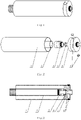
Fig. 1 is a three-dimensional schematic diagram of a combined powder cleaning gun. -
Fig. 2 is a schematic disassembly diagram of the combined powder cleaning gun. -
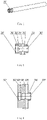
Fig. 3 is a section view of the combined powder cleaning gun. -
Fig. 4 is a three-dimensional schematic diagram of the central gun barrel. -
Fig. 5 is a section view of the front combined unit. -
Fig. 6 is a section view of the rear combined unit. - In which: 1 ball socket and platform gun barrel, 2 central gun barrel, 3 front combined unit, 4 sealing ring, 5 rear combined unit, 6 small plug; 201 dense micro hole; 301 first internal threaded hole, 302 first splicing section, 303 first sealing section, 304 first powder absorbing hole, 305 first powder absorbing section, 306 first external threaded section, 307 first powder absorbing through hole; 501 second internal threaded hole, 502 second splicing section, 503 second sealing section, 504 second powder absorbing hole, 505 second powder absorbing section, 506 second external threaded section, 507 second powder absorbing through hole.
- The present invention will be further described in detail below in combination with embodiments and the accompanying drawings.
- An automatic powder cleaning system for mixed-line hub bolt holes includes a control system, a recognition system, a powder cleaning robot, a gun storage and accessory device, wherein the recognition system and the powder cleaning robot are connected with the control system by adopting electroweak system, a plurality of combined powder spraying guns are arranged in the gun storage, a quick disassembly fixture is arranged at the end of the powder cleaning robot, and the process flow of the powder cleaning system includes: storing a powder cleaning program, recognizing a wheel type, entering a powder room and spraying powder, entering a powder cleaning station, calling the powder cleaning program, replacing a gun for the robot, cleaning powder, and completing powder cleaning.
- A combined powder cleaning gun for the automatic powder cleaning system for mixed-line hub bolt holes includes, as shown in
Figs. 1-6 , includes a combined gun body and a gun barrel. The combined gun body includes a front combinedunit 3 and a rear combinedunit 5. The lateral surface of the front combinedunit 3 includes a frontfirst splicing section 302 and a rear firstpowder absorbing section 305. The rear combinedunit 5 includes a frontsecond splicing section 502 and a rear secondpowder absorbing section 505. The diameters of the firstpowder absorbing section 305 and the secondpowder absorbing section 505 are respectively greater than those of thefirst splicing section 302 and thesecond splicing section 502. A first powder absorbing throughhole 307 and a second powder absorbing throughhole 507 are respectively formed in the centers of the front combinedunit 3 and the rear combinedunit 5. The firstpowder absorbing section 305 and the secondpowder absorbing section 505 are respectively provided with a firstpowder absorbing hole 304 and a second powder absorbing hole 504.The firstpowder absorbing hole 304 and the secondpowder absorbing hole 504 are respectively perpendicular to the axes of the front combinedunit 3 and the rear combinedunit 5 and are respectively intersected with the first powder absorbing throughhole 307 and the second powder absorbing throughhole 507. The diameters of thesecond splicing section 502 and the secondpowder absorbing section 505 of the rear combinedunit 5 are respectively greater than those of thefirst splicing section 302 and the firstpowder absorbing section 305 of the front combined unit. An first internal threadedhole 301 and an second internal threadedhole 501 are formed in the front ends of the first powder absorbing throughhole 307 and the second powder absorbing throughhole 507 of the front combinedunit 3 and the rear combinedunit 5. An first external threadedsection 306 and an second external threadedsection 506 are formed at the tail ends of the front combinedunit 3 and the rear combinedunit 5. The first internal threadedhole 301 can be matched with the first external threadedsection 306. The second internal threadedhole 501 can be matched with the second external threadedsection 506. The first internal threadedhole 301 and the second internal threadedhole 501 are completely same in size, and the first external threadedsection 306 and the second external threadedsection 506 are completely same in size. The gun barrel includes acentral gun barrel 2 and a ball socket andplatform gun barrel 1. The tail of thecentral gun barrel 2 is connected with thefirst splicing section 302 of the front combinedunit 3. The tail of the ball socket andplatform gun barrel 1 is connected with thesecond splicing section 502 of the rear combinedunit 5. The head of thecentral gun barrel 2 protrudes out of the head of the ball socket andplatform gun barrel 1. Densemicro holes 201 are formed in the side wall of the head of thecentral gun barrel 2. Thecentral gun barrel 2 and the ball socket andplatform gun barrel 1 are made of a carbon fiber material. Twosmall plugs 6 are provided to plug the secondpowder absorbing hole 504 of the rear combinedunit 5, and thesmall plugs 6 are made of a soft material. Afirst sealing section 303 and asecond sealing section 503 are respectively formed adjacent to the first internal threadedhole 301 and the second internal threadedhole 501, and asealing ring 4 is installed between the rear end face of the first external threadedsection 303 of the front combinedunit 3 and thesecond sealing section 503 of the rear combinedunit 5.
Claims (5)
- A combined powder cleaning gun for an automatic powder cleaning system for mixed-line hub bolt holes, comprising a combined gun body and a gun barrel, wherein the combined gun body includes front and rear combined units (3, 5), the lateral surface of each combined unit (3, 5) includes a front splicing section (302, 502) and a rear powder absorbing section (305, 505), the diameter of the powder absorbing section (305, 505) is greater than that of the splicing section (302, 502), a powder absorbing through hole (307, 507) is formed in the center of each combined unit (3, 5), and the powder absorbing section (305, 505) of each combined unit (3, 5) is provided with a powder absorbing hole (304, 504); the diameters of the splicing section (502) and the powder absorbing section (505) of the rear combined unit (5) are respectively greater than those of the splicing section (302) and the powder absorbing section (305) of the front combined unit (3), and a connecting device is arranged at each of the front and rear ends of each combined unit (3, 5); the gun barrel comprises a central gun barrel (2) and a ball socket and platform gun barrel, the tail of the central gun barrel (2) is connected with the splicing section (302) of the front combined unit (3), the tail of the ball socket and platform gun barrel is connected with the splicing section (502) of the rear combined unit (5), the head of the central gun barrel (2) protrudes out of the head of the ball socket and platform gun barrel,characterized in that dense micro holes (201) are formed in the side wall of the head of the central gun barrel (2), and two small plugs are provided to plug the powder absorbing hole (504) of the rear combined unit (5),and in that the connecting devices of each combined unit (3, 5) refer to an internal threaded hole (301, 501) formed in the front end of the powder absorbing through hole (307, 507) of each combined unit (3, 5) and an external threaded section (306, 506) formed at the tail end of each combined unit (3, 5), the internal threaded hole (301, 501) and the external threaded section (306, 506) of each combined unit (3, 5) adopt mutually matched sizes, and the sizes of the internal threaded hole (301, 501) and the external threaded section (306, 506) of the each combined unit (3, 5) are completely same, wherein a sealing section (303, 503) is formed adjacent to the internal threaded hole (301, 501) of the combined unit (3, 5), and a sealing ring (4) is installed between the rear end face of the external threaded section (306) of the front combined unit (3) and the sealing section (503) of the rear combined unit (5).
- The combined automatic powder cleaning gun for hub bolt holes as described in claim 1, characterized in that the powder absorbing hole (304, 504) of the powder absorbing section (305, 505) of the combined unit (5, 6) is perpendicular to the axis of the combined unit (5, 6), and is intersected with the powder absorbing through hole (307, 507) of the combined unit (5, 6).
- An automatic powder cleaning system for mixed-line hub bolt holes, comprising a control system, a recognition system, a powder cleaning robot, a gun storage and an accessory device, characterized in that the recognition system and the powder cleaning robot are connected with the control system by adopting electroweak system, a plurality of combined powder spraying guns as described in claim 1 or 2 are arranged in the gun storage, a quick disassembly fixture is arranged at the end of the powder cleaning robot, the automatic powder cleaning system comprising means for a process flow of the powder cleaning system to comprise: storing a powder cleaning program, recognizing a wheel type, entering a powder room and spraying powder, entering a powder cleaning station, calling the powder cleaning program, replacing a gun by the robot, cleaning powder, and completing powder cleaning.
- The automatic powder cleaning system for mixed-line hub bolt holes as described in claim 3, characterized in that: the recognition system is a visual recognition system, and is used for recognizing and inputting all wheel type image information before production and editing wheel type code information, and the wheel type code information corresponds one-to-one to images.
- The automatic powder cleaning system for mixed-line hub bolt holes as described in claim 3 or 4, characterized in that: the recognition system refers to a bar code or two-dimensional code set at a specific position of a hub and a code reading device arranged at a wheel type recognition station, and the code reading device is connected with the control system by adopting electroweak system.
Applications Claiming Priority (1)
| Application Number | Priority Date | Filing Date | Title |
|---|---|---|---|
| CN201710495266.1A CN107262320B (en) | 2017-06-26 | 2017-06-26 | Automatic powder cleaning system for mixed-wire type hub bolt hole and combined powder cleaning gun |
Publications (2)
| Publication Number | Publication Date |
|---|---|
| EP3421146A1 EP3421146A1 (en) | 2019-01-02 |
| EP3421146B1 true EP3421146B1 (en) | 2022-04-13 |
Family
ID=60068898
Family Applications (1)
| Application Number | Title | Priority Date | Filing Date |
|---|---|---|---|
| EP18179552.7A Active EP3421146B1 (en) | 2017-06-26 | 2018-06-25 | Combined powder cleaning gun for an automatic powder cleaning system for mixed-line hub bolt holes |
Country Status (4)
| Country | Link |
|---|---|
| US (1) | US10639681B2 (en) |
| EP (1) | EP3421146B1 (en) |
| CN (1) | CN107262320B (en) |
| MA (1) | MA44564B1 (en) |
Families Citing this family (3)
| Publication number | Priority date | Publication date | Assignee | Title |
|---|---|---|---|---|
| CN108816684B (en) * | 2018-06-21 | 2024-05-10 | 格力电器(芜湖)有限公司 | Device for removing powder on surface of bolt |
| CN112774366B (en) * | 2020-12-21 | 2021-10-29 | 上海征世科技股份有限公司 | Diamond cutting waste material dust recycling equipment |
| CN113160162B (en) * | 2021-04-14 | 2022-02-18 | 深圳远荣智能制造股份有限公司 | Hole recognition method and device applied to workpiece and hole processing equipment |
Family Cites Families (82)
| Publication number | Priority date | Publication date | Assignee | Title |
|---|---|---|---|---|
| US2995393A (en) * | 1957-10-30 | 1961-08-08 | Nalco Chemical Co | Method and apparatus for increasing the coefficient of friction between metal surfaces |
| US3617000A (en) * | 1969-06-16 | 1971-11-02 | Ransburg Electro Coating Corp | Spray gun for applying solid particles |
| DE2020055A1 (en) * | 1970-04-24 | 1971-12-02 | Mueller Ernst Kg | Method and device for covering objects with powdery substances |
| US3667675A (en) * | 1971-02-16 | 1972-06-06 | Graco Inc | Electrostatic powder coating apparatus |
| US3740612A (en) * | 1971-05-28 | 1973-06-19 | Champion Spark Plug Co | Apparatus for coating with electrostatically charged particulate materials |
| US3688990A (en) * | 1971-08-04 | 1972-09-05 | Atlas Copco Ab | Spray gun |
| GB1386247A (en) * | 1971-08-05 | 1975-03-05 | Vertue C R F | Device for delivering particulate material |
| US3873024A (en) * | 1971-08-13 | 1975-03-25 | Ransburg Corp | Apparatus for spraying a plurality of different powders |
| US3844477A (en) * | 1971-11-18 | 1974-10-29 | Ransburg Electro Coating Corp | Electrostatic powder spray gun |
| SE371942B (en) * | 1972-03-13 | 1974-12-09 | Atlas Copco Ab | |
| US3870232A (en) * | 1972-05-26 | 1975-03-11 | Air Ind | Nozzle for projecting powdered solid products |
| FR2283729A1 (en) * | 1974-09-06 | 1976-04-02 | Air Ind | ELECTROSTATIC PROJECTION NOZZLE FOR POWDERED PRODUCTS |
| US3940061A (en) * | 1974-09-16 | 1976-02-24 | Champion Spark Plug Company | Electrostatic spray gun for powder coating material |
| JPS5145143A (en) * | 1974-10-16 | 1976-04-17 | Ransburg Japan Ltd | Funshapataanno choseiga kanona funtaitosoyofunshanozuru |
| US4169560A (en) * | 1975-03-29 | 1979-10-02 | Elektrostatische Spritz-- und Beflockungsgesellschaft G.F. Vohringer GmbH | Electrostatic spray gun for powdered material |
| US3964683A (en) * | 1975-09-02 | 1976-06-22 | Champion Spark Plug Company | Electrostatic spray apparatus |
| ES468633A1 (en) * | 1978-04-07 | 1978-12-01 | Rosal Vila Juan | Devices for covering objects with electrostatic dust |
| SE438966B (en) * | 1978-12-04 | 1985-05-28 | Gema Ransburg Ag | SPRAY DEVICE FOR POWDER WITH SPRAY GAS SPECIFICALLY INTRODUCED IN THE NOZZLE OPENING |
| NL188933C (en) * | 1980-01-04 | 1992-11-16 | Icab Ind Coating Ab | Device for spraying solid particles in powder form. |
| DE3014133C2 (en) * | 1980-04-12 | 1984-04-19 | Ransburg-Gema AG, 9015 St.Gallen | Device for atomizing powder |
| US4380320A (en) * | 1981-02-25 | 1983-04-19 | Nordson Corporation | Electrostatic powder spray gun nozzle |
| DE3412694A1 (en) * | 1983-04-07 | 1984-10-11 | Kopperschmidt-Mueller GmbH & Co KG, 7057 Winnenden | METHOD AND DEVICE FOR ELECTROSTATICALLY SPRAYING ON POWDER PARTICLES ON A SURFACE TO BE COATED |
| DE3330665A1 (en) * | 1983-08-25 | 1985-03-14 | Weitmann & Konrad GmbH & Co KG, 7022 Leinfelden-Echterdingen | DEVICE FOR DUSTING MOVING OBJECTS, IN PARTICULAR AREA DOCUMENTS |
| US4630777A (en) * | 1984-02-27 | 1986-12-23 | Nordson Corporation | Powder spray gun |
| US4634058A (en) * | 1984-12-13 | 1987-01-06 | Nordson Corporation | Powder spray gun |
| DE3514523A1 (en) * | 1985-04-22 | 1986-10-23 | Ransburg-Gema AG, St. Gallen | METHOD AND DEVICE FOR THE ELECTROSTATIC COATING OF OBJECTS WITH POWDER-SHAPED COATING MATERIAL |
| US4638951A (en) * | 1985-05-09 | 1987-01-27 | Nordson Corporation | Adjustable powder spray nozzle |
| DE3601081A1 (en) * | 1986-01-16 | 1987-07-23 | Kopperschmidt Mueller & Co | ELECTROSTATIC SPRAY GUN, ESPECIALLY FOR POWDER |
| US4815666A (en) * | 1987-09-21 | 1989-03-28 | Nordson Corporation | Powder spray gun for quick color changes systems |
| JP2668696B2 (en) * | 1988-03-04 | 1997-10-27 | 大成建設株式会社 | Method to prevent peeling and scattering of asbestos-containing substances |
| DE3904438A1 (en) * | 1989-02-14 | 1990-08-16 | Gema Ransburg Ag | SPRAY COATING DEVICE FOR ELECTROSTATIC SPRAY COATING |
| DE4141663C2 (en) * | 1991-12-17 | 1996-09-19 | Wagner Int | Electrostatic powder coating gun |
| US5520735A (en) * | 1992-06-30 | 1996-05-28 | Nordson Corporation | Nozzle assembly and system for applying powder to a workpiece |
| US5344082A (en) * | 1992-10-05 | 1994-09-06 | Nordson Corporation | Tribo-electric powder spray gun |
| US5341989A (en) * | 1993-02-16 | 1994-08-30 | Nordson Corporation | Electrostatic powder spray gun with hose purge adaptor |
| DE4418288A1 (en) * | 1994-05-26 | 1995-11-30 | Gema Volstatic Ag | Electrostatic spray device |
| US5711489A (en) * | 1994-08-18 | 1998-01-27 | Nihon Parkerizing Co., Ltd. | Electrostatic powder coating method and apparatus |
| US5620138A (en) * | 1994-11-09 | 1997-04-15 | Nordson Corporation | Powder coating gun mounted diffuser and air cooled heat sink in combination with low flow powder pump improvements |
| DE69629330T2 (en) * | 1995-06-01 | 2004-06-17 | Nordson Corp., Westlake | Spray atomizer with counter electrode |
| US5904294A (en) * | 1996-09-13 | 1999-05-18 | Nordson Corporation | Particle spray apparatus and method |
| JPH10314624A (en) * | 1997-05-14 | 1998-12-02 | Nippon Parkerizing Co Ltd | Electrostatic powder coating gun |
| DE19748376A1 (en) * | 1997-11-03 | 1999-05-06 | Itw Gema Ag | Method and device for powder spray coating |
| JP2000033331A (en) * | 1998-07-22 | 2000-02-02 | Topy Ind Ltd | Method of removing powder coating from aluminum wheel hole surface and device therefor |
| US6478242B1 (en) * | 1999-09-16 | 2002-11-12 | Nordson Corporation | Powder spray gun |
| US20030080220A1 (en) * | 1999-09-16 | 2003-05-01 | Mather Brian D. | Powder spray gun with inline angle spray nozzle |
| WO2003031075A1 (en) * | 1999-09-16 | 2003-04-17 | Nordson Corporation | Powder spray gun with inline angle spray nozzle |
| US20020088397A1 (en) * | 2000-05-03 | 2002-07-11 | Perkins Jeffrey A. | Coating system with centralized control panel and gun mapping |
| US20030038192A1 (en) * | 2000-10-05 | 2003-02-27 | Shutic Jeffrey R. | Quick change powder coating spray system |
| US7325750B2 (en) * | 2000-10-05 | 2008-02-05 | Nordson Corporation | Powder coating system with improved overspray collection |
| WO2002092235A2 (en) * | 2000-10-05 | 2002-11-21 | Nordson Corporation | Controlling cyclone efficiency with vacuum interface |
| US6866717B2 (en) * | 2000-10-05 | 2005-03-15 | Nordson Corporation | Powder coating spray booth with air curtain |
| US6730167B2 (en) * | 2000-10-05 | 2004-05-04 | Nordson Corporation | Powder coating spray booth with a powder extraction system |
| WO2002060595A1 (en) * | 2001-01-31 | 2002-08-08 | Nordson Corporation | Powder spray gun mount and cleaning arrangements |
| US20050178851A1 (en) * | 2001-06-25 | 2005-08-18 | Nordson Corporation | Quick change powder coating spray system |
| WO2003080254A2 (en) * | 2002-03-21 | 2003-10-02 | Nordson Corporation | Spray gun cleaning arrangements |
| US6874712B2 (en) * | 2002-09-27 | 2005-04-05 | Abb Inc. | Swirl gun for powder particles |
| US20050098659A1 (en) * | 2002-09-27 | 2005-05-12 | Milojevic Dragoslav K. | Swirl gun for powder particles |
| DE10249999B3 (en) * | 2002-10-26 | 2004-04-15 | EISENMANN Maschinenbau KG (Komplementär: Eisenmann-Stiftung) | Suction device for removal of powder-coated paint from automobile wheel using electronic camera image for detecting wheel axial and angular position for controlling movement device for suction head |
| US6817553B2 (en) * | 2003-02-04 | 2004-11-16 | Efc Systems, Inc. | Powder paint spray coating apparatus having selectable, modular spray applicators |
| DE10318238B4 (en) * | 2003-04-23 | 2007-02-01 | Robert Bosch Gmbh | Method and device for cleaning internal surfaces of threaded holes |
| US20040245673A1 (en) * | 2003-06-09 | 2004-12-09 | Allsop Robert J. | Wear components in powder coating system |
| FR2857279B1 (en) * | 2003-07-07 | 2005-08-26 | Eisenmann France Sarl | POWDER DIFFUSION NOZZLE FOR ELECTROSTATIC JET ORIENTING POWDER DEVICE |
| US20050126476A1 (en) * | 2003-11-05 | 2005-06-16 | Nordson Corporation | Improved particulate material application system |
| US20060144963A1 (en) * | 2003-08-18 | 2006-07-06 | Fulkerson Terrence M | Spray applicator for particulate material |
| US20050115496A1 (en) * | 2003-11-05 | 2005-06-02 | Nordson Corporation | Supply for dry particulate material |
| US20070266939A1 (en) * | 2003-11-20 | 2007-11-22 | Mitsuyoshi Kumata | Powder Coating System |
| US7913938B2 (en) * | 2004-11-12 | 2011-03-29 | Mystic Tan, Inc. | Electrostatic spray nozzle with adjustable fluid tip and interchangeable components |
| DE102005017931A1 (en) * | 2005-04-18 | 2006-10-19 | Itw Gema Ag | Powder spray coating gun and gun body for this purpose |
| DE202005012863U1 (en) * | 2005-08-12 | 2005-10-27 | J. Wagner Ag | Electrode holder in a powder spray unit comprises a strip in the powder channel formed by a sleeve with an electric contact on its rear face |
| US8037844B2 (en) * | 2007-10-31 | 2011-10-18 | Nordson Corporation | Spray gun having display and control members on gun |
| US8726831B2 (en) * | 2007-10-31 | 2014-05-20 | Nordson Corporation | Apparatus and methods for purging material application device |
| FR2944980B1 (en) * | 2009-04-29 | 2012-12-14 | Arkema France | DEVICE AND METHOD FOR SPRAYING |
| JP5943290B2 (en) * | 2010-05-31 | 2016-07-05 | いすゞ自動車株式会社 | Electrostatic coating method and electrostatic coating gun |
| JP2012232273A (en) * | 2011-05-09 | 2012-11-29 | Asahi Sansho Kk | Cleaning brush for hole drilling |
| CN202224298U (en) * | 2011-09-22 | 2012-05-23 | 天津立中车轮有限公司 | Protective plugging device for vacuum tire rim bolt holes |
| CN104245147B (en) * | 2012-04-12 | 2018-11-06 | 诺信公司 | Powder spray gun including wear-resistant electrode support |
| EP2836307A1 (en) * | 2012-04-13 | 2015-02-18 | Nordson Corporation | Powder gun configurable for supply from venturi or dense phase pump |
| WO2014014502A1 (en) * | 2012-07-16 | 2014-01-23 | Nordson Corporation | Powder gun configurable for supply from venturi or dense phase pump |
| DE102013205362A1 (en) * | 2013-03-26 | 2014-10-02 | Gema Switzerland Gmbh | Spray coating gun for spray coating objects with coating powder |
| JP2015127047A (en) * | 2013-11-26 | 2015-07-09 | 曙ブレーキ工業株式会社 | Powder application system, powder application method, manufacturing method of caliper, and caliper |
| DE102015216272A1 (en) * | 2015-08-26 | 2017-03-02 | Airbus Operations Gmbh | Modular robot kit, swarm of modularized robots, and task accomplishment by a swarm of modularized robots |
| CN206810555U (en) * | 2017-06-26 | 2017-12-29 | 中信戴卡股份有限公司 | A kind of Combined hub bolt hole clear powder rifle automatically |
-
2017
- 2017-06-26 CN CN201710495266.1A patent/CN107262320B/en active Active
- 2017-08-10 US US15/673,931 patent/US10639681B2/en active Active
-
2018
- 2018-06-25 MA MA44564A patent/MA44564B1/en unknown
- 2018-06-25 EP EP18179552.7A patent/EP3421146B1/en active Active
Also Published As
| Publication number | Publication date |
|---|---|
| US10639681B2 (en) | 2020-05-05 |
| CN107262320B (en) | 2023-08-29 |
| CN107262320A (en) | 2017-10-20 |
| EP3421146A1 (en) | 2019-01-02 |
| MA44564B1 (en) | 2022-08-31 |
| US20180369878A1 (en) | 2018-12-27 |
Similar Documents
| Publication | Publication Date | Title |
|---|---|---|
| EP3421146A1 (en) | Automatic powder cleaning system for mixed-line hub bolt holes and combined powder cleaning gun | |
| CN104841592B (en) | A kind of automatic spray unit of intelligence based on number bus and its application method | |
| EP3390140B1 (en) | Method for providing energy between an energy supplier and a motor vehicle | |
| CN109833999A (en) | Workpiece rotating device and the coating process for using the Workpiece rotating device | |
| EP3310939B1 (en) | Thermal spraying process and thermal sprayer | |
| DE202011000150U1 (en) | change coupling | |
| EP3296679A1 (en) | Centering device for attaching barrel | |
| CN105415382A (en) | Intelligent automobile body paint-spraying manipulator for automobile maintenance | |
| CN204685361U (en) | Based on the intelligent automatic coating unit of number bus | |
| US10493480B2 (en) | Device for the automatic powder cleaning process for wheel bolt holes | |
| CN105964469B (en) | Shelter type automatic spraying system and method | |
| CN204685362U (en) | Intelligence automatic coating unit spray coating mechanical hand | |
| CN111102878B (en) | Thermal spraying and sealing equipment for grease of gun barrel | |
| CN105163867A (en) | Powder coating system | |
| CN223486290U (en) | Replaceable pin type coding mark point for laser projection positioning system | |
| JP6233161B2 (en) | Passenger conveyor inspection device | |
| CN203293194U (en) | Turning manipulator for engine cylinder body | |
| CN203437244U (en) | Locking device and spraying gun with locking device | |
| CN104923453A (en) | Coating protection device | |
| CN106111415A (en) | Paint airless spraying color separation anti-splashing guard shield baffle plate | |
| CN206810555U (en) | A kind of Combined hub bolt hole clear powder rifle automatically | |
| CN105290658B (en) | Workpiece welding missing preventing device for motor vehicle | |
| CN114932024A (en) | Electrostatic spraying device for hub and electrostatic spraying process thereof | |
| CN216473482U (en) | Annular coaxial powder feeding device for laser cladding | |
| KR102874446B1 (en) | Powder coating system |
Legal Events
| Date | Code | Title | Description |
|---|---|---|---|
| PUAI | Public reference made under article 153(3) epc to a published international application that has entered the european phase |
Free format text: ORIGINAL CODE: 0009012 |
|
| STAA | Information on the status of an ep patent application or granted ep patent |
Free format text: STATUS: REQUEST FOR EXAMINATION WAS MADE |
|
| 17P | Request for examination filed |
Effective date: 20180625 |
|
| AK | Designated contracting states |
Kind code of ref document: A1 Designated state(s): AL AT BE BG CH CY CZ DE DK EE ES FI FR GB GR HR HU IE IS IT LI LT LU LV MC MK MT NL NO PL PT RO RS SE SI SK SM TR |
|
| AX | Request for extension of the european patent |
Extension state: BA ME |
|
| GRAP | Despatch of communication of intention to grant a patent |
Free format text: ORIGINAL CODE: EPIDOSNIGR1 |
|
| STAA | Information on the status of an ep patent application or granted ep patent |
Free format text: STATUS: GRANT OF PATENT IS INTENDED |
|
| GRAS | Grant fee paid |
Free format text: ORIGINAL CODE: EPIDOSNIGR3 |
|
| INTG | Intention to grant announced |
Effective date: 20211104 |
|
| GRAA | (expected) grant |
Free format text: ORIGINAL CODE: 0009210 |
|
| STAA | Information on the status of an ep patent application or granted ep patent |
Free format text: STATUS: THE PATENT HAS BEEN GRANTED |
|
| AK | Designated contracting states |
Kind code of ref document: B1 Designated state(s): AL AT BE BG CH CY CZ DE DK EE ES FI FR GB GR HR HU IE IS IT LI LT LU LV MC MK MT NL NO PL PT RO RS SE SI SK SM TR |
|
| REG | Reference to a national code |
Ref country code: GB Ref legal event code: FG4D |
|
| REG | Reference to a national code |
Ref country code: CH Ref legal event code: EP |
|
| REG | Reference to a national code |
Ref country code: DE Ref legal event code: R096 Ref document number: 602018033671 Country of ref document: DE |
|
| REG | Reference to a national code |
Ref country code: IE Ref legal event code: FG4D |
|
| REG | Reference to a national code |
Ref country code: AT Ref legal event code: REF Ref document number: 1482993 Country of ref document: AT Kind code of ref document: T Effective date: 20220515 |
|
| REG | Reference to a national code |
Ref country code: LT Ref legal event code: MG9D |
|
| REG | Reference to a national code |
Ref country code: NL Ref legal event code: MP Effective date: 20220413 |
|
| REG | Reference to a national code |
Ref country code: MA Ref legal event code: VAGR Ref document number: 44564 Country of ref document: MA Kind code of ref document: B1 |
|
| REG | Reference to a national code |
Ref country code: AT Ref legal event code: MK05 Ref document number: 1482993 Country of ref document: AT Kind code of ref document: T Effective date: 20220413 |
|
| PG25 | Lapsed in a contracting state [announced via postgrant information from national office to epo] |
Ref country code: NL Free format text: LAPSE BECAUSE OF FAILURE TO SUBMIT A TRANSLATION OF THE DESCRIPTION OR TO PAY THE FEE WITHIN THE PRESCRIBED TIME-LIMIT Effective date: 20220413 |
|
| PG25 | Lapsed in a contracting state [announced via postgrant information from national office to epo] |
Ref country code: SE Free format text: LAPSE BECAUSE OF FAILURE TO SUBMIT A TRANSLATION OF THE DESCRIPTION OR TO PAY THE FEE WITHIN THE PRESCRIBED TIME-LIMIT Effective date: 20220413 Ref country code: PT Free format text: LAPSE BECAUSE OF FAILURE TO SUBMIT A TRANSLATION OF THE DESCRIPTION OR TO PAY THE FEE WITHIN THE PRESCRIBED TIME-LIMIT Effective date: 20220816 Ref country code: NO Free format text: LAPSE BECAUSE OF FAILURE TO SUBMIT A TRANSLATION OF THE DESCRIPTION OR TO PAY THE FEE WITHIN THE PRESCRIBED TIME-LIMIT Effective date: 20220713 Ref country code: LT Free format text: LAPSE BECAUSE OF FAILURE TO SUBMIT A TRANSLATION OF THE DESCRIPTION OR TO PAY THE FEE WITHIN THE PRESCRIBED TIME-LIMIT Effective date: 20220413 Ref country code: HR Free format text: LAPSE BECAUSE OF FAILURE TO SUBMIT A TRANSLATION OF THE DESCRIPTION OR TO PAY THE FEE WITHIN THE PRESCRIBED TIME-LIMIT Effective date: 20220413 Ref country code: GR Free format text: LAPSE BECAUSE OF FAILURE TO SUBMIT A TRANSLATION OF THE DESCRIPTION OR TO PAY THE FEE WITHIN THE PRESCRIBED TIME-LIMIT Effective date: 20220714 Ref country code: FI Free format text: LAPSE BECAUSE OF FAILURE TO SUBMIT A TRANSLATION OF THE DESCRIPTION OR TO PAY THE FEE WITHIN THE PRESCRIBED TIME-LIMIT Effective date: 20220413 Ref country code: ES Free format text: LAPSE BECAUSE OF FAILURE TO SUBMIT A TRANSLATION OF THE DESCRIPTION OR TO PAY THE FEE WITHIN THE PRESCRIBED TIME-LIMIT Effective date: 20220413 Ref country code: BG Free format text: LAPSE BECAUSE OF FAILURE TO SUBMIT A TRANSLATION OF THE DESCRIPTION OR TO PAY THE FEE WITHIN THE PRESCRIBED TIME-LIMIT Effective date: 20220713 Ref country code: AT Free format text: LAPSE BECAUSE OF FAILURE TO SUBMIT A TRANSLATION OF THE DESCRIPTION OR TO PAY THE FEE WITHIN THE PRESCRIBED TIME-LIMIT Effective date: 20220413 |
|
| PG25 | Lapsed in a contracting state [announced via postgrant information from national office to epo] |
Ref country code: RS Free format text: LAPSE BECAUSE OF FAILURE TO SUBMIT A TRANSLATION OF THE DESCRIPTION OR TO PAY THE FEE WITHIN THE PRESCRIBED TIME-LIMIT Effective date: 20220413 Ref country code: PL Free format text: LAPSE BECAUSE OF FAILURE TO SUBMIT A TRANSLATION OF THE DESCRIPTION OR TO PAY THE FEE WITHIN THE PRESCRIBED TIME-LIMIT Effective date: 20220413 Ref country code: LV Free format text: LAPSE BECAUSE OF FAILURE TO SUBMIT A TRANSLATION OF THE DESCRIPTION OR TO PAY THE FEE WITHIN THE PRESCRIBED TIME-LIMIT Effective date: 20220413 Ref country code: IS Free format text: LAPSE BECAUSE OF FAILURE TO SUBMIT A TRANSLATION OF THE DESCRIPTION OR TO PAY THE FEE WITHIN THE PRESCRIBED TIME-LIMIT Effective date: 20220813 |
|
| REG | Reference to a national code |
Ref country code: DE Ref legal event code: R097 Ref document number: 602018033671 Country of ref document: DE |
|
| PG25 | Lapsed in a contracting state [announced via postgrant information from national office to epo] |
Ref country code: SM Free format text: LAPSE BECAUSE OF FAILURE TO SUBMIT A TRANSLATION OF THE DESCRIPTION OR TO PAY THE FEE WITHIN THE PRESCRIBED TIME-LIMIT Effective date: 20220413 Ref country code: SK Free format text: LAPSE BECAUSE OF FAILURE TO SUBMIT A TRANSLATION OF THE DESCRIPTION OR TO PAY THE FEE WITHIN THE PRESCRIBED TIME-LIMIT Effective date: 20220413 Ref country code: RO Free format text: LAPSE BECAUSE OF FAILURE TO SUBMIT A TRANSLATION OF THE DESCRIPTION OR TO PAY THE FEE WITHIN THE PRESCRIBED TIME-LIMIT Effective date: 20220413 Ref country code: MC Free format text: LAPSE BECAUSE OF FAILURE TO SUBMIT A TRANSLATION OF THE DESCRIPTION OR TO PAY THE FEE WITHIN THE PRESCRIBED TIME-LIMIT Effective date: 20220413 Ref country code: EE Free format text: LAPSE BECAUSE OF FAILURE TO SUBMIT A TRANSLATION OF THE DESCRIPTION OR TO PAY THE FEE WITHIN THE PRESCRIBED TIME-LIMIT Effective date: 20220413 Ref country code: DK Free format text: LAPSE BECAUSE OF FAILURE TO SUBMIT A TRANSLATION OF THE DESCRIPTION OR TO PAY THE FEE WITHIN THE PRESCRIBED TIME-LIMIT Effective date: 20220413 Ref country code: CZ Free format text: LAPSE BECAUSE OF FAILURE TO SUBMIT A TRANSLATION OF THE DESCRIPTION OR TO PAY THE FEE WITHIN THE PRESCRIBED TIME-LIMIT Effective date: 20220413 |
|
| REG | Reference to a national code |
Ref country code: CH Ref legal event code: PL |
|
| PLBE | No opposition filed within time limit |
Free format text: ORIGINAL CODE: 0009261 |
|
| STAA | Information on the status of an ep patent application or granted ep patent |
Free format text: STATUS: NO OPPOSITION FILED WITHIN TIME LIMIT |
|
| REG | Reference to a national code |
Ref country code: BE Ref legal event code: MM Effective date: 20220630 |
|
| 26N | No opposition filed |
Effective date: 20230116 |
|
| GBPC | Gb: european patent ceased through non-payment of renewal fee |
Effective date: 20220713 |
|
| PG25 | Lapsed in a contracting state [announced via postgrant information from national office to epo] |
Ref country code: AL Free format text: LAPSE BECAUSE OF FAILURE TO SUBMIT A TRANSLATION OF THE DESCRIPTION OR TO PAY THE FEE WITHIN THE PRESCRIBED TIME-LIMIT Effective date: 20220413 |
|
| PG25 | Lapsed in a contracting state [announced via postgrant information from national office to epo] |
Ref country code: LU Free format text: LAPSE BECAUSE OF NON-PAYMENT OF DUE FEES Effective date: 20220625 Ref country code: LI Free format text: LAPSE BECAUSE OF NON-PAYMENT OF DUE FEES Effective date: 20220630 Ref country code: IE Free format text: LAPSE BECAUSE OF NON-PAYMENT OF DUE FEES Effective date: 20220625 Ref country code: CH Free format text: LAPSE BECAUSE OF NON-PAYMENT OF DUE FEES Effective date: 20220630 |
|
| PG25 | Lapsed in a contracting state [announced via postgrant information from national office to epo] |
Ref country code: SI Free format text: LAPSE BECAUSE OF FAILURE TO SUBMIT A TRANSLATION OF THE DESCRIPTION OR TO PAY THE FEE WITHIN THE PRESCRIBED TIME-LIMIT Effective date: 20220413 Ref country code: GB Free format text: LAPSE BECAUSE OF NON-PAYMENT OF DUE FEES Effective date: 20220713 Ref country code: BE Free format text: LAPSE BECAUSE OF NON-PAYMENT OF DUE FEES Effective date: 20220630 |
|
| PG25 | Lapsed in a contracting state [announced via postgrant information from national office to epo] |
Ref country code: IT Free format text: LAPSE BECAUSE OF FAILURE TO SUBMIT A TRANSLATION OF THE DESCRIPTION OR TO PAY THE FEE WITHIN THE PRESCRIBED TIME-LIMIT Effective date: 20220413 |
|
| PG25 | Lapsed in a contracting state [announced via postgrant information from national office to epo] |
Ref country code: HU Free format text: LAPSE BECAUSE OF FAILURE TO SUBMIT A TRANSLATION OF THE DESCRIPTION OR TO PAY THE FEE WITHIN THE PRESCRIBED TIME-LIMIT; INVALID AB INITIO Effective date: 20180625 |
|
| PG25 | Lapsed in a contracting state [announced via postgrant information from national office to epo] |
Ref country code: MK Free format text: LAPSE BECAUSE OF FAILURE TO SUBMIT A TRANSLATION OF THE DESCRIPTION OR TO PAY THE FEE WITHIN THE PRESCRIBED TIME-LIMIT Effective date: 20220413 Ref country code: CY Free format text: LAPSE BECAUSE OF FAILURE TO SUBMIT A TRANSLATION OF THE DESCRIPTION OR TO PAY THE FEE WITHIN THE PRESCRIBED TIME-LIMIT Effective date: 20220413 |
|
| PG25 | Lapsed in a contracting state [announced via postgrant information from national office to epo] |
Ref country code: MT Free format text: LAPSE BECAUSE OF FAILURE TO SUBMIT A TRANSLATION OF THE DESCRIPTION OR TO PAY THE FEE WITHIN THE PRESCRIBED TIME-LIMIT Effective date: 20220413 |
|
| PG25 | Lapsed in a contracting state [announced via postgrant information from national office to epo] |
Ref country code: BG Free format text: LAPSE BECAUSE OF FAILURE TO SUBMIT A TRANSLATION OF THE DESCRIPTION OR TO PAY THE FEE WITHIN THE PRESCRIBED TIME-LIMIT Effective date: 20220413 |
|
| PG25 | Lapsed in a contracting state [announced via postgrant information from national office to epo] |
Ref country code: BG Free format text: LAPSE BECAUSE OF FAILURE TO SUBMIT A TRANSLATION OF THE DESCRIPTION OR TO PAY THE FEE WITHIN THE PRESCRIBED TIME-LIMIT Effective date: 20220413 |
|
| PGFP | Annual fee paid to national office [announced via postgrant information from national office to epo] |
Ref country code: DE Payment date: 20250617 Year of fee payment: 8 |
|
| PGFP | Annual fee paid to national office [announced via postgrant information from national office to epo] |
Ref country code: FR Payment date: 20250630 Year of fee payment: 8 |
|
| VS25 | Lapsed in a validation state [announced via postgrant information from nat. office to epo] |
Ref country code: MA Free format text: LAPSE BECAUSE OF NON-PAYMENT OF DUE FEES Effective date: 20230626 |
|
| VSFP | Annual fee paid to validation state [announced via postgrant information from national office to epo] |
Ref country code: MA Payment date: 20220627 Year of fee payment: 5 |
|
| PG25 | Lapsed in a contracting state [announced via postgrant information from national office to epo] |
Ref country code: TR Free format text: LAPSE BECAUSE OF FAILURE TO SUBMIT A TRANSLATION OF THE DESCRIPTION OR TO PAY THE FEE WITHIN THE PRESCRIBED TIME-LIMIT Effective date: 20220413 |