EP3390140B1 - Method for providing energy between an energy supplier and a motor vehicle - Google Patents
Method for providing energy between an energy supplier and a motor vehicle Download PDFInfo
- Publication number
- EP3390140B1 EP3390140B1 EP16829073.2A EP16829073A EP3390140B1 EP 3390140 B1 EP3390140 B1 EP 3390140B1 EP 16829073 A EP16829073 A EP 16829073A EP 3390140 B1 EP3390140 B1 EP 3390140B1
- Authority
- EP
- European Patent Office
- Prior art keywords
- energy supply
- unit
- supply interface
- vehicle
- motor vehicle
- Prior art date
- Legal status (The legal status is an assumption and is not a legal conclusion. Google has not performed a legal analysis and makes no representation as to the accuracy of the status listed.)
- Active
Links
- 238000000034 method Methods 0.000 title claims description 56
- 238000004891 communication Methods 0.000 claims description 28
- 238000012545 processing Methods 0.000 claims description 11
- 230000008878 coupling Effects 0.000 claims description 6
- 238000010168 coupling process Methods 0.000 claims description 6
- 238000005859 coupling reaction Methods 0.000 claims description 6
- 230000011664 signaling Effects 0.000 claims 1
- 230000008569 process Effects 0.000 description 14
- 238000001514 detection method Methods 0.000 description 6
- 230000009466 transformation Effects 0.000 description 4
- 230000008901 benefit Effects 0.000 description 3
- 238000011161 development Methods 0.000 description 3
- 230000018109 developmental process Effects 0.000 description 3
- 239000000446 fuel Substances 0.000 description 3
- 230000003287 optical effect Effects 0.000 description 3
- 238000012549 training Methods 0.000 description 3
- 238000013459 approach Methods 0.000 description 2
- 230000009286 beneficial effect Effects 0.000 description 2
- 238000005516 engineering process Methods 0.000 description 2
- 230000001939 inductive effect Effects 0.000 description 2
- 239000003550 marker Substances 0.000 description 2
- 238000005259 measurement Methods 0.000 description 2
- UFHFLCQGNIYNRP-UHFFFAOYSA-N Hydrogen Chemical compound [H][H] UFHFLCQGNIYNRP-UHFFFAOYSA-N 0.000 description 1
- 235000004522 Pentaglottis sempervirens Nutrition 0.000 description 1
- 230000001133 acceleration Effects 0.000 description 1
- 238000012790 confirmation Methods 0.000 description 1
- 238000010276 construction Methods 0.000 description 1
- 238000012937 correction Methods 0.000 description 1
- 230000001419 dependent effect Effects 0.000 description 1
- 238000013461 design Methods 0.000 description 1
- 230000000694 effects Effects 0.000 description 1
- 230000005611 electricity Effects 0.000 description 1
- 239000007789 gas Substances 0.000 description 1
- 239000001257 hydrogen Substances 0.000 description 1
- 229910052739 hydrogen Inorganic materials 0.000 description 1
- 239000007788 liquid Substances 0.000 description 1
- 238000012986 modification Methods 0.000 description 1
- 230000004048 modification Effects 0.000 description 1
- 238000010079 rubber tapping Methods 0.000 description 1
- 239000000126 substance Substances 0.000 description 1
- 239000000725 suspension Substances 0.000 description 1
- 238000011426 transformation method Methods 0.000 description 1
- 230000000007 visual effect Effects 0.000 description 1
Images


Classifications
-
- B—PERFORMING OPERATIONS; TRANSPORTING
- B60—VEHICLES IN GENERAL
- B60L—PROPULSION OF ELECTRICALLY-PROPELLED VEHICLES; SUPPLYING ELECTRIC POWER FOR AUXILIARY EQUIPMENT OF ELECTRICALLY-PROPELLED VEHICLES; ELECTRODYNAMIC BRAKE SYSTEMS FOR VEHICLES IN GENERAL; MAGNETIC SUSPENSION OR LEVITATION FOR VEHICLES; MONITORING OPERATING VARIABLES OF ELECTRICALLY-PROPELLED VEHICLES; ELECTRIC SAFETY DEVICES FOR ELECTRICALLY-PROPELLED VEHICLES
- B60L53/00—Methods of charging batteries, specially adapted for electric vehicles; Charging stations or on-board charging equipment therefor; Exchange of energy storage elements in electric vehicles
- B60L53/10—Methods of charging batteries, specially adapted for electric vehicles; Charging stations or on-board charging equipment therefor; Exchange of energy storage elements in electric vehicles characterised by the energy transfer between the charging station and the vehicle
- B60L53/14—Conductive energy transfer
-
- B—PERFORMING OPERATIONS; TRANSPORTING
- B60—VEHICLES IN GENERAL
- B60L—PROPULSION OF ELECTRICALLY-PROPELLED VEHICLES; SUPPLYING ELECTRIC POWER FOR AUXILIARY EQUIPMENT OF ELECTRICALLY-PROPELLED VEHICLES; ELECTRODYNAMIC BRAKE SYSTEMS FOR VEHICLES IN GENERAL; MAGNETIC SUSPENSION OR LEVITATION FOR VEHICLES; MONITORING OPERATING VARIABLES OF ELECTRICALLY-PROPELLED VEHICLES; ELECTRIC SAFETY DEVICES FOR ELECTRICALLY-PROPELLED VEHICLES
- B60L53/00—Methods of charging batteries, specially adapted for electric vehicles; Charging stations or on-board charging equipment therefor; Exchange of energy storage elements in electric vehicles
- B60L53/30—Constructional details of charging stations
- B60L53/305—Communication interfaces
-
- B—PERFORMING OPERATIONS; TRANSPORTING
- B60—VEHICLES IN GENERAL
- B60L—PROPULSION OF ELECTRICALLY-PROPELLED VEHICLES; SUPPLYING ELECTRIC POWER FOR AUXILIARY EQUIPMENT OF ELECTRICALLY-PROPELLED VEHICLES; ELECTRODYNAMIC BRAKE SYSTEMS FOR VEHICLES IN GENERAL; MAGNETIC SUSPENSION OR LEVITATION FOR VEHICLES; MONITORING OPERATING VARIABLES OF ELECTRICALLY-PROPELLED VEHICLES; ELECTRIC SAFETY DEVICES FOR ELECTRICALLY-PROPELLED VEHICLES
- B60L53/00—Methods of charging batteries, specially adapted for electric vehicles; Charging stations or on-board charging equipment therefor; Exchange of energy storage elements in electric vehicles
- B60L53/30—Constructional details of charging stations
- B60L53/35—Means for automatic or assisted adjustment of the relative position of charging devices and vehicles
- B60L53/36—Means for automatic or assisted adjustment of the relative position of charging devices and vehicles by positioning the vehicle
-
- B—PERFORMING OPERATIONS; TRANSPORTING
- B60—VEHICLES IN GENERAL
- B60L—PROPULSION OF ELECTRICALLY-PROPELLED VEHICLES; SUPPLYING ELECTRIC POWER FOR AUXILIARY EQUIPMENT OF ELECTRICALLY-PROPELLED VEHICLES; ELECTRODYNAMIC BRAKE SYSTEMS FOR VEHICLES IN GENERAL; MAGNETIC SUSPENSION OR LEVITATION FOR VEHICLES; MONITORING OPERATING VARIABLES OF ELECTRICALLY-PROPELLED VEHICLES; ELECTRIC SAFETY DEVICES FOR ELECTRICALLY-PROPELLED VEHICLES
- B60L53/00—Methods of charging batteries, specially adapted for electric vehicles; Charging stations or on-board charging equipment therefor; Exchange of energy storage elements in electric vehicles
- B60L53/30—Constructional details of charging stations
- B60L53/35—Means for automatic or assisted adjustment of the relative position of charging devices and vehicles
- B60L53/37—Means for automatic or assisted adjustment of the relative position of charging devices and vehicles using optical position determination, e.g. using cameras
-
- B—PERFORMING OPERATIONS; TRANSPORTING
- B60—VEHICLES IN GENERAL
- B60Y—INDEXING SCHEME RELATING TO ASPECTS CROSS-CUTTING VEHICLE TECHNOLOGY
- B60Y2200/00—Type of vehicle
- B60Y2200/90—Vehicles comprising electric prime movers
- B60Y2200/91—Electric vehicles
-
- Y—GENERAL TAGGING OF NEW TECHNOLOGICAL DEVELOPMENTS; GENERAL TAGGING OF CROSS-SECTIONAL TECHNOLOGIES SPANNING OVER SEVERAL SECTIONS OF THE IPC; TECHNICAL SUBJECTS COVERED BY FORMER USPC CROSS-REFERENCE ART COLLECTIONS [XRACs] AND DIGESTS
- Y02—TECHNOLOGIES OR APPLICATIONS FOR MITIGATION OR ADAPTATION AGAINST CLIMATE CHANGE
- Y02T—CLIMATE CHANGE MITIGATION TECHNOLOGIES RELATED TO TRANSPORTATION
- Y02T10/00—Road transport of goods or passengers
- Y02T10/60—Other road transportation technologies with climate change mitigation effect
- Y02T10/70—Energy storage systems for electromobility, e.g. batteries
-
- Y—GENERAL TAGGING OF NEW TECHNOLOGICAL DEVELOPMENTS; GENERAL TAGGING OF CROSS-SECTIONAL TECHNOLOGIES SPANNING OVER SEVERAL SECTIONS OF THE IPC; TECHNICAL SUBJECTS COVERED BY FORMER USPC CROSS-REFERENCE ART COLLECTIONS [XRACs] AND DIGESTS
- Y02—TECHNOLOGIES OR APPLICATIONS FOR MITIGATION OR ADAPTATION AGAINST CLIMATE CHANGE
- Y02T—CLIMATE CHANGE MITIGATION TECHNOLOGIES RELATED TO TRANSPORTATION
- Y02T10/00—Road transport of goods or passengers
- Y02T10/60—Other road transportation technologies with climate change mitigation effect
- Y02T10/7072—Electromobility specific charging systems or methods for batteries, ultracapacitors, supercapacitors or double-layer capacitors
-
- Y—GENERAL TAGGING OF NEW TECHNOLOGICAL DEVELOPMENTS; GENERAL TAGGING OF CROSS-SECTIONAL TECHNOLOGIES SPANNING OVER SEVERAL SECTIONS OF THE IPC; TECHNICAL SUBJECTS COVERED BY FORMER USPC CROSS-REFERENCE ART COLLECTIONS [XRACs] AND DIGESTS
- Y02—TECHNOLOGIES OR APPLICATIONS FOR MITIGATION OR ADAPTATION AGAINST CLIMATE CHANGE
- Y02T—CLIMATE CHANGE MITIGATION TECHNOLOGIES RELATED TO TRANSPORTATION
- Y02T90/00—Enabling technologies or technologies with a potential or indirect contribution to GHG emissions mitigation
- Y02T90/10—Technologies relating to charging of electric vehicles
- Y02T90/12—Electric charging stations
-
- Y—GENERAL TAGGING OF NEW TECHNOLOGICAL DEVELOPMENTS; GENERAL TAGGING OF CROSS-SECTIONAL TECHNOLOGIES SPANNING OVER SEVERAL SECTIONS OF THE IPC; TECHNICAL SUBJECTS COVERED BY FORMER USPC CROSS-REFERENCE ART COLLECTIONS [XRACs] AND DIGESTS
- Y02—TECHNOLOGIES OR APPLICATIONS FOR MITIGATION OR ADAPTATION AGAINST CLIMATE CHANGE
- Y02T—CLIMATE CHANGE MITIGATION TECHNOLOGIES RELATED TO TRANSPORTATION
- Y02T90/00—Enabling technologies or technologies with a potential or indirect contribution to GHG emissions mitigation
- Y02T90/10—Technologies relating to charging of electric vehicles
- Y02T90/14—Plug-in electric vehicles
-
- Y—GENERAL TAGGING OF NEW TECHNOLOGICAL DEVELOPMENTS; GENERAL TAGGING OF CROSS-SECTIONAL TECHNOLOGIES SPANNING OVER SEVERAL SECTIONS OF THE IPC; TECHNICAL SUBJECTS COVERED BY FORMER USPC CROSS-REFERENCE ART COLLECTIONS [XRACs] AND DIGESTS
- Y02—TECHNOLOGIES OR APPLICATIONS FOR MITIGATION OR ADAPTATION AGAINST CLIMATE CHANGE
- Y02T—CLIMATE CHANGE MITIGATION TECHNOLOGIES RELATED TO TRANSPORTATION
- Y02T90/00—Enabling technologies or technologies with a potential or indirect contribution to GHG emissions mitigation
- Y02T90/10—Technologies relating to charging of electric vehicles
- Y02T90/16—Information or communication technologies improving the operation of electric vehicles
Definitions
- the invention relates to a method for carrying out at least one energy supply operation between an energy supply unit and at least one motor vehicle to be supplied with energy, with the features of the preamble of patent claim 1.
- the invention further relates to a motor vehicle and an energy supply unit for performing the method.
- a power supply unit (charging unit) which can be moved on a rail and which can drive to a large number of parking spaces in a parking space and can supply parked electric vehicles with electrical current.
- the movable charging unit is equipped with an image capture device in the form of a camera, which is used to identify a position of an energy supply interface (charging interface) of a motor vehicle to be charged.
- an energy supply interface (charging interface) of a motor vehicle to be charged.
- suitable visual features for example lamps, markings or reflectors.
- the charging unit can access a plurality of charging cables by means of a robot arm, which are arranged at the head end of the parking spaces from the parking space.
- the robot removes the charging cable by tapping an associated charging plug from a suspension and then plugging it into the charging interface of the motor vehicle to be charged.
- the robot In order to synchronize the charging process between an electric vehicle to be charged and the charging unit, at least confirmation of the charging process by the vehicle driver is required. Communication of the motor vehicle with the charging unit is therefore made possible via a communication device, for example via a WLAN port.
- an energy supply unit which is equipped with a multi-articulated robot arm which is used for positioning and connecting a charging plug to a charging socket of a motor vehicle to be charged.
- the energy supply unit has a detector unit for determining the position of the charging socket of the motor vehicle.
- the detector unit recognizes the position of the charging socket of the motor vehicle on the basis of optical or geometric features of the charging socket.
- a communication device is arranged on the energy supply unit, which is designed to receive information from the motor vehicle and a charge controller.
- a robot charging station for charging a battery of an electric vehicle.
- the robot is movably attached to a standpipe, which is coupled to a base plate.
- the robot contains a gripping element with an electrical plug, which is used for coupling to a vehicle-mounted charging socket.
- a sensor is present in the base plate, which uses optical, acoustic or also RFID-based detection means.
- the arm of the robot also contains a camera in the vicinity of the plug in order to detect the position of a vehicle-mounted charging socket and thus to be able to move the gripping member of the robot precisely to the vehicle-side charging socket. It is also proposed to use several cameras in order to be able to provide a stereoscopic view of the motor vehicle and / or its charging socket.
- the above prior art has in common that the position determination of a vehicle-side energy supply interface always takes place on the part of the energy supply unit.
- the DE 10 2013 207 906 A1 such as WO 2014/174361 A2 describe a vehicle-side camera and optically detectable features of the energy supply unit in order to facilitate parking of the vehicle.
- the invention is based on the object of providing a method for carrying out an energy supply process between an energy supply unit and a motor vehicle to be supplied with energy, which method can be carried out simply and efficiently.
- the invention is based on the object of providing a suitable motor vehicle and a suitable energy supply unit for carrying out the method.
- the invention is initially based on a method for carrying out an energy supply process between an energy supply unit and a motor vehicle to be supplied with energy.
- a position of a vehicle-side energy supply interface is determined and there is an automated coupling between the vehicle-side energy supply interface and an energy supply interface of the energy supply unit.
- the automated coupling is accomplished in that the energy supply interface of the energy supply unit is moved by a robot to the vehicle-side energy supply interface and is coupled to it.
- the position of the vehicle-side energy supply interface relative to the energy supply unit be determined by the motor vehicle itself before the energy supply process is carried out and transmitted from the motor vehicle to the energy supply unit.
- the energy supply unit Before carrying out an energy supply process, it is not necessary for the energy supply unit to carry out a position detection of the vehicle-side energy supply interface. This can lead to time advantages in particular if several motor vehicles are to be operated with one energy supply unit.
- a second motor vehicle to be supplied can then already determine the position of its energy supply interface relative to the energy supply unit and transmit it to the energy supply unit while a first motor vehicle is already being supplied with energy.
- a first motor vehicle is already being supplied with energy.
- the robot already knows the position data and can approach it directly.
- energy is not only electrical energy in the form of electricity, but also chemical energy in the form of liquid or gaseous fuel (e.g. gasoline, diesel, gas, hydrogen) can act.
- liquid or gaseous fuel e.g. gasoline, diesel, gas, hydrogen
- the term “energy supply unit” is also to be understood, which can be designed, for example, in the manner of a charging station for electrical current, a fuel dispenser for fuel or the like. A combination of such training is conceivable against the background of hybrid vehicles.
- the robot can be structurally integrated as a structural unit in the energy supply unit, but does not have to be.
- the robot can also be designed as a separately controllable movement device for the energy supply interface of the energy supply unit.
- robot in the sense of the invention is to be understood to mean any device which is suitable for moving an energy supply interface of the energy supply unit and for coupling it to an energy supply interface of a motor vehicle.
- a robot can therefore be understood as a simple actuator, but also a complex industrial robot with several degrees of freedom.
- the position of the vehicle-side energy supply interface is determined on the basis of optically detectable features of the energy supply unit.
- optically detectable features can be detected well and reliably with available image capture devices, such as cameras or scanners.
- Features that can be detected optically can be, for example, markings applied to the energy supply unit or special geometric shapes of the energy supply unit.
- a type of sensor bar in which a depth sensor, a webcam, a 3D microphone and an acceleration sensor are combined with one another.
- a depth sensor e.g., a depth sensor
- a webcam e.g., a 3D microphone
- an acceleration sensor e.g., a 3D microphone
- striking geometric points of the energy supply unit in the room can be measured very well.
- markings or geometric shapes of the energy supply unit can be detected precisely and inexpensively using the known triangulation method.
- Photonic mixer devices work according to the principle of the light pulse method, in which objects are illuminated by light pulses and the signal transit time is measured. The distance between the camera and the object can be calculated based on the runtime.
- the markings can be used as reflective stickers or reflective hemispheres (i.e. as passive markings) or self-luminous, e.g. B. as light emitting diodes (ie as active markings).
- known positions of the coordinate transformation can also be used to infer the position of the vehicle-side energy supply interface.
- the exact position of an image capturing device for example camera or scanner
- the position of the image capturing device is determined relative to the optically detectable features of the energy supply unit, the position of the vehicle-side energy supply interface relative to the optically detectable features of the energy supply unit can accordingly be inferred.
- the position of the vehicle-side energy supply interface is additionally determined by the robot on the basis of optically detectable features in the area of the vehicle-side energy supply interface. Such a redundancy in the measurement can increase the accuracy of the position determination.
- the position of the vehicle-side energy supply interface is carried out solely by at least one image capture device which is arranged on the robot.
- the motor vehicle to be supplied has an energy supply interface around which at least three optically detectable features are attached around the outside, which are unevenly arranged with respect to a reference point of the energy supply interface these are distributed and / or coded in each case.
- the invention also relates to a motor vehicle for carrying out the method according to the invention.
- This is characterized in that it has at least one image capturing device, an image processing unit for processing the captured image signals, a storage unit, a comparison unit, a computing unit and a communication unit.
- the image acquisition device, the processing unit, the storage unit, the comparison unit, the computing unit and the communication unit are connected to one another in terms of signal technology. They are designed in such a way that features of the energy supply unit that can be optically detected can be detected by the image capturing device and that a detected feature pattern can be compared with a reference pattern stored in the storage unit. In the event of a positive comparison with the reference pattern, a position of the vehicle-side energy supply interface relative to the energy supply unit can be calculated by the computing unit on the basis of the recorded feature pattern. This position can then be transmitted to the energy supply unit via the communication unit.
- the image capturing device can be designed, for example, as a commercially available webcam or as a laser scanner.
- a communication unit for example, training as a WLAN port or other wireless communication, such as Bluetooth, is conceivable.
- optically detectable features are preferably glued on as markings.
- Non-uniform in the sense of the invention means that the optically detectable features are arranged differently in their radial distance from such a reference point and / or that they are arranged at different angular distances from one another within a full angle of 360 degrees around this reference point.
- the accuracy of the position detection is beneficial if four optically detectable features are present.
- the reliability of the position detection can also be improved or accelerated if each of the markings is coded.
- Such coding can be implemented, for example, by a circular pattern which is interrupted at different points.
- the motor vehicle has an energy supply interface to which a frame-like component is fastened, which has a different color than the energy supply interface itself.
- energy supply interfaces designed as electrical sockets are usually black. This makes image recognition considerably more difficult. If a frame-like component which is, for example, in the color gray or white is applied to the energy supply interface, a good contrast can be created in a simple manner and the image recognition can be facilitated.
- the invention also relates to an energy supply unit for carrying out the method according to the invention.
- This has at least one robot for moving at least one energy supply interface of the energy supply unit to an energy supply interface of a motor vehicle.
- the energy supply unit is provided with at least one communication device, which can be designed, for example, as a WLAN port or as another wireless radio connection (for example Bluetooth).
- the energy supply unit is characterized in that it is provided with several optically detectable features and the at least one communication device is designed at least for communication with a vehicle-side communication device.
- the communication can be carried out in such a way that at least position data of the vehicle-side energy supply interface can be received relative to the energy supply unit.
- optically detectable features are preferably applied to the energy supply unit in the form of markings.
- the optically detectable features of the energy supply unit can also be arranged unevenly distributed around the energy supply interface with respect to a reference point of the energy supply interface.
- each of the optically detectable features can be encoded. The coding can equally be done via circular rings interrupted at different points.
- the energy supply unit 1 is designed as a parking space that can be approached by electric vehicles for electrically charging the electric vehicles.
- Two parking space markings 12 can be seen in front of the energy supply unit 1, within which motor vehicles to be charged can be parked.
- motor vehicles to be charged can be automatically parked within the parking space markings by means of an inductive control system LS and released for charging.
- the energy supply unit 1 has two identically constructed charging stations 10, between which a robot 11 for operating both charging stations 10 is arranged. A different number of charging stations as well as a different number of robots is conceivable.
- the robot 11 is designed as a multi-arm and multi-articulated industrial robot. It has a gripping device 109 with which it can grip and move an energy supply interface 100 of the charging station 10 in the form of a charging plug (see double arrows).
- the robot 11 can use the gripping device 109 to pull the charging plug 100 together with a charging cable 101 out of the charging station 10.
- the charging cable 101 is held in a storage space 102 of the charging station 10 so that it can be wound up.
- a motor vehicle (electric vehicle) K1 to be charged can also be carried on the basis of the control system LS a tolerance of about five centimeters can be parked within a parking space marker 12.
- the gripping device 109 of the robot 11 grips the charging plug 100, moves it to a vehicle-side energy supply interface 2 of the motor vehicle K1 to be charged in the form of a charging socket, and couples it to the latter.
- the robot 11 In order for such a coupling to be possible smoothly, the robot 11 must first know the exact position of the charging socket 2.
- the motor vehicle K1 is equipped in the area of the mirror base of its inside mirror (not shown) with an image capturing device 4 in the form of a stereoscopic camera. This recognizes its own position relative to the charging station 10 on the basis of optically detectable features of the charging station 10, which will be explained in more detail later.
- the motor vehicle K1 Via a vehicle's own coordinate system KO3, the motor vehicle K1 knows exactly where the camera 4 is located and, with the help of common coordinate transformation methods, also where the charging socket 2 is located relative to the camera 4. Such a coordinate transformation is carried out with the aid of a computing unit 8.
- the position data of the charging socket 2 can then be transmitted relative to the charging station 10 by means of a communication device 3, for example in the form of a WLAN port, to a communication device 103 of the charging station 10 which can likewise be configured as a WLAN port.
- a communication device 3 for example in the form of a WLAN port
- a communication device 103 of the charging station 10 which can likewise be configured as a WLAN port.
- an image processing unit 5, a comparison unit 6 and a storage unit 7 of the motor vehicle K1 are indicated by dashed lines.
- the image processing unit 5 is used to process the optical features of the charging station 10 recorded by the camera 4.
- the comparison unit 6 is used to compare a feature pattern recorded by the camera 4 with a reference pattern stored in the storage unit 7.
- the camera 4, the image processing unit 5, the comparison unit 6, the storage unit 7, the computing unit 8 and the communication device 3 are connected to one another in terms of signal technology.
- the charging stations 10 can also each be equipped with an image processing unit 104, a comparison unit 105, a storage unit 106 and a computing unit 107. This is particularly useful if the position of the charging socket 2 is to be determined alternatively or additionally by the robot 11.
- the gripping device 109 can be equipped with an image capturing device 110, which is preferably designed as a commercially available and therefore inexpensive webcam.
- a control unit 108 assigned to the robot 11 is used to control the robot 11 as a function of the position data of the charging socket 2 transmitted to it.
- KO1 is a coordinate system of the energy supply unit 1 and KO2 is a coordinate system of the robot 11.
- the computing unit 107 can also, based on known methods of coordinate transformation, relate to the relative position of the charging socket 2 relative to the coordinate system KO2 Close the robot and transmit this position data to the control unit 108.
- Each charging station 10 is thus provided with four optically detectable features M1-1, M1-2, M1-3 and M1-4 in the form of markings on a wall facing a motor vehicle to be charged.
- the markings mentioned are glued on as reflective, high-contrast markings.
- Each of the markings is coded, the markings being designed as circular figures and the coding being implemented in each case by the number of interruptions in the circle.
- the marking M1-1 has one interruption, the marking M1-2 two interruptions, the marking M1-3 three and the marking M1-4 four interruptions in a circle.
- the markings mentioned are arranged unevenly around a specific reference point 111 of the charging plug 100.
- the reference point 111 can be, for example, an earth contact of the charging plug 100.
- This figure shows the charging socket 2 of the motor vehicle K1, which is designed in such a way that its position can alternatively or additionally also be detected by the aforementioned image capturing device 110 of the robot 11.
- the markings M2-1 to M2-4 are also arranged unevenly around the charging socket 2. Specifically, the markings mentioned have different radial distances r1 to r4 or different radii to a reference point 20 of the charging socket 2.
- the reference point 20 can be, for example, a ground contact of the charging socket 2.
- the markings mentioned have different angular distances ⁇ 1 to ⁇ 4 from one another.
- the markings M2-1 to M2-4 are coded in the same way as the markings M1-1 to M1-4.
- the accuracy and speed of image recognition can be significantly improved by the non-uniform arrangement of the markings around the reference points and / or by their coding.
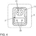
- FIG. 4 An alternative embodiment of a motor vehicle in the area of the charging socket 2 is also explained, the alternative embodiment also significantly facilitating recognition of the charging socket 2 by an image capturing device.
- the edge of the charging socket 2 is covered with a frame-like component 13 which is detachably (for example, latching) attached to the charging socket 2.
- the frame-like component 13 is preferably made of a light gray or white plastic. In this way, a very good contrast effect can be achieved, so that the image recognition is considerably simplified for the image capture device 110 of the robot 11.
- K2 is a second motor vehicle to be charged, which was parked within a second parking space marker 12.
- An advantage of the method according to the invention is that the motor vehicle K2, which is comparable in construction to the motor vehicle K1, locates the position of its charging socket relative to the charging station 10 regardless of the availability of the robot 11 and this position to the communication device 103 of the motor vehicle K2 Charging station 10 can transmit.
- the robot 11 As soon as the robot 11 has coupled the first charging plug 100 to the charging socket 2 of the motor vehicle K1, the latter (already knowing the coordinates of the charging socket of the motor vehicle K2) can grip the second charging plug 100 assigned to the motor vehicle K2. The charging plug 100 can then with the Charging socket of the motor vehicle K2 can be coupled without the robot 11 having to determine the position of this charging socket again.
- a method step V1 the Fig. 5 First, the motor vehicle K1 is automatically parked within the parking space marking 12 with a centimeter tolerance of preferably 5 cm.
- the marking pattern around the charging plug 100 of the charging station 10, which results from the markings M1-1 to M1-4, is then recognized by an image recognition of the on-board camera 4 (method step V2).
- a comparison of the recognized marking pattern with a stored reference pattern is carried out.
- a query A1 asks whether the recognized marking pattern matches the stored reference pattern. If not, a compensating movement on the part of the motor vehicle K1 to be charged must be carried out in a method step V1 '.
- the position of the on-board camera 4 is calculated relative to the energy supply unit, in particular relative to a reference point of the energy supply unit.
- a position of the vehicle's charging socket 2 relative to the energy supply unit 1 is calculated via coordinate transformation (method step V4).
- the position coordinates are then transmitted to the communication device 103 of the charging station 10 (method step V5). Thereafter, in a method step V6, the charging plug 100 of the charging station 10 is moved by the robot 11 to the vehicle-side charging socket 2 and coupled to it.
- a query A2 queries whether the motor vehicle is charged or not.
- the charging plug 100 is finally uncoupled from the charging socket 2 by the robot 11 in a method step V7 and moved back to the charging station 10.
- a process VR (indicated by dashed lines) can be initiated, which comprises the method steps VR1 to VR6 (cf. Figure 6 ).
- a method step VR1 the image capture device 110 on the robot 11 is moved up to the vehicle-side charging socket 2.
- a method step VR2 the marking pattern formed by the markings M2-1 to M2-4 is recognized. A comparison with a stored reference pattern takes place in method step VR3.
- the position coordinates of the vehicle's own charging socket 2 are calculated by the computing unit 107 of the charging station 10 and transferred to the control unit 108 of the energy supply unit 1 (VR4).
- the charging plug 100 of the charging station 10 is moved by means of the robot 11 to the vehicle-side charging socket 2 and coupled to it (method step VR5).
- a query AR2 is used to check whether the motor vehicle K1 to be charged is charged or not. After charging has taken place, the charging plug 100 is disconnected from the charging socket 2 again by the robot 11 in a method step VR6 and moved back to the charging station 1.
- the position of the vehicle-side charging socket 2 is carried out solely by the image capture device 110, which is attached to the robot 11 in the vicinity of the gripping device 109.
- the motor vehicle K1 has a charging socket 2, around which at least the three markings M2-1 to M2-4 are attached, which unevenly with respect to a reference point of the charging socket 2 these are distributed and / or coded in each case.
Landscapes
- Engineering & Computer Science (AREA)
- Power Engineering (AREA)
- Transportation (AREA)
- Mechanical Engineering (AREA)
- Charge And Discharge Circuits For Batteries Or The Like (AREA)
- Electric Propulsion And Braking For Vehicles (AREA)
- Manipulator (AREA)
- Image Analysis (AREA)
Description
Die Erfindung betrifft ein Verfahren zur Durchführung wenigstens eines Energieversorgungsvorgangs zwischen einer Energieversorgungseinheit und wenigstens einem mit Energie zu versorgenden Kraftfahrzeug mit den Merkmalen vom Oberbegriff des Patentanspruchs 1.The invention relates to a method for carrying out at least one energy supply operation between an energy supply unit and at least one motor vehicle to be supplied with energy, with the features of the preamble of
Die Erfindung betrifft ferner ein Kraftfahrzeug und eine Energieversorgungseinheit zur Durchführung des Verfahrens.The invention further relates to a motor vehicle and an energy supply unit for performing the method.
Aus den Dokumenten
Konkret wird bei der
Die verfahrbare Ladeeinheit ist mit einer Bilderfassungseinrichtung in Form einer Kamera ausgerüstet, welche zur Erkennung einer Position einer Energieversorgungs-Schnittstelle (Ladeschnittstelle) eines aufzuladenden Kraftfahrzeugs dient. Zur Vereinfachung der Bilderkennung wird vorgeschlagen, die Ladeschnittstelle mit geeigneten visuellen Merkmalen, beispielsweise Lampen, Markierungen oder Reflektoren zu versehen.
Es wird ferner vorgeschlagen, dass die Ladeeinheit mittels eines Roboterarms auf mehrere Ladekabel zugreifen kann, welche am Kopfende der Parkplätze vom Abstellplatz angeordnet sind. Der Roboter entnimmt jeweils nach dem Anfahren eines Parkplatzes das Ladekabel, indem er einen zugehörigen Ladestecker von einer Aufhängung abgreift und anschließend in die Ladeschnittstelle des aufzuladenden Kraftfahrzeugs steckt. Um den Ladevorgang zwischen einem aufzuladenden Elektrofahrzeug und der Ladeeinheit zu synchronisieren ist zumindest eine Bestätigung des Ladevorgangs durch den Fahrzeugführer erforderlich. Daher wird eine Kommunikation des Kraftfahrzeugs mit der Ladeeinheit über eine Kommunikationseinrichtung, beispielsweise über einen WLAN-Port ermöglicht.Specifically, at
The movable charging unit is equipped with an image capture device in the form of a camera, which is used to identify a position of an energy supply interface (charging interface) of a motor vehicle to be charged. To simplify image recognition, it is proposed to provide the charging interface with suitable visual features, for example lamps, markings or reflectors.
It is also proposed that the charging unit can access a plurality of charging cables by means of a robot arm, which are arranged at the head end of the parking spaces from the parking space. Each time the robot approaches a parking space, the robot removes the charging cable by tapping an associated charging plug from a suspension and then plugging it into the charging interface of the motor vehicle to be charged. In order to synchronize the charging process between an electric vehicle to be charged and the charging unit, at least confirmation of the charging process by the vehicle driver is required. Communication of the motor vehicle with the charging unit is therefore made possible via a communication device, for example via a WLAN port.
In der
Ferner ist an der Energieversorgungseinheit eine Kommunikationseinrichtung angeordnet, welche zum Empfangen von Informationen des Kraftfahrzeugs und eines Ladereglers ausgebildet ist. Der Laderegler dient zum Initiieren eines Beginns oder eines Abbruchs eines Ladevorgangs auf Basis des Ladezustands vom Kraftfahrzeug.
Es wird auch vorgeschlagen, die Detektoreinheit zur Ermittlung der Position der Ladebuchse auf Basis eines RFID-Chips auszubilden (RFID = Radio Frequency Identification).In the
Furthermore, a communication device is arranged on the energy supply unit, which is designed to receive information from the motor vehicle and a charge controller. The charge controller is used to initiate a start or an abort of a charging process based on the state of charge of the motor vehicle.
It is also proposed to design the detector unit to determine the position of the charging socket on the basis of an RFID chip (RFID = Radio Frequency Identification).
Schließlich wird in der
Der Roboter enthält ein Greiforgan mit einem elektrischen Stecker, welcher zur Kopplung mit einer fahrzeugseitigen Ladedose dient.
Zur Anwesenheitserfassung eines aufzuladenden Kraftfahrzeugs ist in der Basisplatte ein Sensor vorhanden, welcher optische, akustische oder auch RFID-basierte Erfassungsmittel verwendet.
Der Arm des Roboters enthält in der Nähe des Steckers ferner eine Kamera um die Position einer fahrzeugseitigen Ladedose zu erfassen und das Greiforgan des Roboters somit genau zur fahrzeugseitigen Ladedose bewegen zu können. Es wird auch vorgeschlagen, mehrere Kameras zu verwenden, um eine stereoskopische Ansicht des Kraftfahrzeugs und/oder dessen Ladedose bereitstellen zu können.Finally, in the
The robot contains a gripping element with an electrical plug, which is used for coupling to a vehicle-mounted charging socket.
For the presence detection of a motor vehicle to be charged, a sensor is present in the base plate, which uses optical, acoustic or also RFID-based detection means.
The arm of the robot also contains a camera in the vicinity of the plug in order to detect the position of a vehicle-mounted charging socket and thus to be able to move the gripping member of the robot precisely to the vehicle-side charging socket. It is also proposed to use several cameras in order to be able to provide a stereoscopic view of the motor vehicle and / or its charging socket.
Dem obigen Stand der Technik ist gemeinsam, dass die Positionsermittlung einer fahrzeugseitigen Energieversorgungs-Schnittstelle immer seitens der Energieversorgungseinheit erfolgt.The above prior art has in common that the position determination of a vehicle-side energy supply interface always takes place on the part of the energy supply unit.
Aus der
Die
Der Erfindung liegt die Aufgabe zu Grunde, ein Verfahren zur Durchführung eines Energieversorgungsvorgangs zwischen einer Energieversorgungseinheit und einem mit Energie zu versorgenden Kraftfahrzeug bereitzustellen, welches einfach und effizient durchführbar ist.The invention is based on the object of providing a method for carrying out an energy supply process between an energy supply unit and a motor vehicle to be supplied with energy, which method can be carried out simply and efficiently.
Des Weiteren liegt der Erfindung die Aufgabe zu Grunde, ein geeignetes Kraftfahrzeug und eine geeignete Energieversorgungseinheit zur Durchführung des Verfahrens bereitzustellen.Furthermore, the invention is based on the object of providing a suitable motor vehicle and a suitable energy supply unit for carrying out the method.
Vorliegende Aufgaben werden durch die Merkmale von Patentanspruch 1, 4 und 8 gelöst. Vorteilhafte Ausbildungen beziehungsweise Weiterbildungen der Erfindung sind den jeweiligen abhängigen Ansprüchen zu entnehmen.Present tasks are solved by the features of
Die Erfindung geht zunächst von einem Verfahren zur Durchführung eines Energieversorgungsvorgangs zwischen einer Energieversorgungseinheit und einem mit Energie zu versorgenden Kraftfahrzeug aus. Dabei wird eine Position einer fahrzeugseitigen Energieversorgungs-Schnittstelle ermittelt und es erfolgt eine automatisierte Kopplung zwischen der fahrzeugseitigen Energieversorgungs-Schnittstelle und einer Energieversorgungs-Schnittstelle der Energieversorgungseinheit. Die automatisierte Kopplung wird dadurch bewerkstelligt, dass die Energieversorgungs-Schnittstelle der Energieversorgungseinheit durch einen Roboter zur fahrzeugseitigen Energieversorgungs-Schnittstelle bewegt und mit dieser gekoppelt wird.The invention is initially based on a method for carrying out an energy supply process between an energy supply unit and a motor vehicle to be supplied with energy. In this case, a position of a vehicle-side energy supply interface is determined and there is an automated coupling between the vehicle-side energy supply interface and an energy supply interface of the energy supply unit. The automated coupling is accomplished in that the energy supply interface of the energy supply unit is moved by a robot to the vehicle-side energy supply interface and is coupled to it.
Erfindungsgemäß wird nun vorgeschlagen, dass die Position der fahrzeugseitigen Energieversorgungs-Schnittstelle relativ zur Energieversorgungseinheit vor Durchführung des Energieversorgungsvorgangs durch das Kraftfahrzeug selbst ermittelt und vom Kraftfahrzeug an die Energieversorgungseinheit übermittelt wird.According to the invention, it is now proposed that the position of the vehicle-side energy supply interface relative to the energy supply unit be determined by the motor vehicle itself before the energy supply process is carried out and transmitted from the motor vehicle to the energy supply unit.
Auf diese Weise kann das Verfahren sehr effizient gestaltet werden.In this way, the process can be designed very efficiently.
Somit ist es vor der Durchführung eines Energieversorgungsvorgangs nicht notwendig, dass seitens der Energieversorgungseinheit eine Positionserkennung der fahrzeugseitigen Energieversorgungs-Schnittstelle durchgeführt wird. Dies kann insbesondere dann zu Zeitvorteilen führen, wenn mit einer Energieversorgungseinheit mehrere Kraftfahrzeuge bedient werden sollen.Thus, before carrying out an energy supply process, it is not necessary for the energy supply unit to carry out a position detection of the vehicle-side energy supply interface. This can lead to time advantages in particular if several motor vehicles are to be operated with one energy supply unit.
So kann beispielsweise ein zweites zu versorgendes Kraftfahrzeug bereits dann die Position seiner Energieversorgungs-Schnittstelle relativ zur Energieversorgungseinheit ermitteln und an die Energieversorgungseinheit übermitteln, während ein erstes Kraftfahrzeug bereits mit Energie versorgt wird. Beim Beginn des Energieversorgungsvorgangs für das zweite Kraftfahrzeug ist eine vorherige Ermittlung der Position der fahrzeugseitigen Energieversorgungs-Schnittstelle dann nicht mehr notwendig, was einen entsprechenden Zeitvorteil mit sich bringt. Der Roboter kennt bereits die Positionsdaten und kann diese direkt anfahren.For example, a second motor vehicle to be supplied can then already determine the position of its energy supply interface relative to the energy supply unit and transmit it to the energy supply unit while a first motor vehicle is already being supplied with energy. At the beginning of the energy supply process for the second motor vehicle, it is then no longer necessary to determine the position of the vehicle-side energy supply interface beforehand, which is a corresponding step Saves time. The robot already knows the position data and can approach it directly.
Es ist ausdrücklich darauf hinzuweisen, dass es sich bei dem Begriff "Energie" nicht nur um elektrische Energie in Form von Strom, sondern auch um chemische Energie in Form von flüssigem oder gasförmigem Kraftstoff (z. B. Benzin, Diesel, Gas, Wasserstoff) handeln kann.It should be expressly pointed out that the term "energy" is not only electrical energy in the form of electricity, but also chemical energy in the form of liquid or gaseous fuel (e.g. gasoline, diesel, gas, hydrogen) can act.
Dementsprechend ist auch der Begriff "Energieversorgungseinheit" zu verstehen, welche beispielsweise in der Art einer Ladestation für elektrischen Strom, einer Zapfsäule für Kraftstoff oder dergleichen ausgebildet sein kann. Eine Kombination solcher Ausbildungen ist vor dem Hintergrund hybrider Fahrzeuge durchaus denkbar.Accordingly, the term “energy supply unit” is also to be understood, which can be designed, for example, in the manner of a charging station for electrical current, a fuel dispenser for fuel or the like. A combination of such training is conceivable against the background of hybrid vehicles.
Des Weiteren kann der Roboter als Baueinheit in die Energieversorgungseinheit baulich integriert sein, muss es aber nicht. Der Roboter kann auch als separat ansteuerbare Bewegungseinrichtung für die Energieversorgungs-Schnittstelle der Energieversorgungseinheit ausgebildet sein. Im Übrigen ist unter "Roboter" im Sinne der Erfindung jede Einrichtung zu verstehen, die geeignet ist, eine Energieversorgungs-Schnittstelle der Energieversorgungseinheit zu bewegen und mit einer Energieversorgungs-Schnittstelle eines Kraftfahrzeugs zu koppeln. In konkreter Ausprägung kann als Roboter daher bereits ein einfacher Aktuator, aber auch ein komplexer Industrieroboter mit mehreren Freiheitsgraden verstanden werden.Furthermore, the robot can be structurally integrated as a structural unit in the energy supply unit, but does not have to be. The robot can also be designed as a separately controllable movement device for the energy supply interface of the energy supply unit. Incidentally, "robot" in the sense of the invention is to be understood to mean any device which is suitable for moving an energy supply interface of the energy supply unit and for coupling it to an energy supply interface of a motor vehicle. In concrete terms, a robot can therefore be understood as a simple actuator, but also a complex industrial robot with several degrees of freedom.
Gemäß einer ersten Weiterbildung der Erfindung wird die Position der fahrzeugseitigen Energieversorgungs-Schnittstelle anhand von optisch erfassbaren Merkmalen der Energieversorgungseinheit ermittelt.According to a first development of the invention, the position of the vehicle-side energy supply interface is determined on the basis of optically detectable features of the energy supply unit.
Dies trägt zur Vereinfachung des Verfahrens bei, da optisch erfassbare Merkmale gut und zuverlässig mit verfügbaren Bilderfassungsgeräten, wie beispielsweise Kameras oder Scannern erfassbar sind.This contributes to simplifying the method, since optically detectable features can be detected well and reliably with available image capture devices, such as cameras or scanners.
Optisch erfassbare Merkmale können beispielsweise auf die Energieversorgungseinheit aufgebrachte Markierungen oder besondere geometrische Formen der Energieversorgungseinheit sein.Features that can be detected optically can be, for example, markings applied to the energy supply unit or special geometric shapes of the energy supply unit.
In diesem Zusammenhang ist darauf hinzuweisen, dass zur Durchführung des erfindungsgemäßen Verfahrens bzw. zur Positionsermittlung einer fahrzeugseitigen Energieversorgungs-Schnittstelle der Einsatz unterschiedlichster Messsysteme denkbar ist.In this context, it should be pointed out that the use of a wide variety of measuring systems is conceivable for carrying out the method according to the invention or for determining the position of a vehicle-side energy supply interface.
So ist beispielsweise der Einsatz einer Art Sensorleiste denkbar, bei dem ein Tiefensensor, eine Webcam, ein 3D-Mikrofon und ein Beschleunigungssensor miteinander kombiniert werden. Hierdurch können markante geometrische Punkte der Energieversorgungseinheit im Raum sehr gut gemessen werden.
Unter Einsatz von Laserscannern können Markierungen oder geometrische Formen der Energieversorgungseinheit mittels des bekannten Triangulationsverfahrens genau und kostengünstig erfasst werden.For example, the use of a type of sensor bar is conceivable, in which a depth sensor, a webcam, a 3D microphone and an acceleration sensor are combined with one another. In this way, striking geometric points of the energy supply unit in the room can be measured very well.
Using laser scanners, markings or geometric shapes of the energy supply unit can be detected precisely and inexpensively using the known triangulation method.
Photomischdetektoren (PMD-Kameras) arbeiten nach dem Prinzip des Lichtimpulsverfahrens, bei dem Messobjekte von Lichtimpulsen angeleuchtet und die Signallaufzeit gemessen wird. Aufgrund der Laufzeit kann die Entfernung zwischen Kamera und Objekt errechnet werden.Photonic mixer devices (PMD cameras) work according to the principle of the light pulse method, in which objects are illuminated by light pulses and the signal transit time is measured. The distance between the camera and the object can be calculated based on the runtime.
Zur räumlichen Messung (Photogrammmetrie) von geometrischen Formen der Energieversorgungseinheit ist der Einsatz mehrerer, wenigstens zweier, nah beieinander angeordneter Kameras denkbar.For the spatial measurement (photogrammetry) of geometric shapes of the energy supply unit, the use of several, at least two, cameras arranged close to one another is conceivable.
Je nach favorisiertem Messsystem können die Markierungen als reflektierende Aufkleber oder reflektierende Halbkugeln (also als passive Markierungen) oder selbstleuchtend, z. B. als Leuchtdioden (also als aktive Markierungen) ausgebildet sein.Depending on the preferred measuring system, the markings can be used as reflective stickers or reflective hemispheres (i.e. as passive markings) or self-luminous, e.g. B. as light emitting diodes (ie as active markings).
Sobald die optisch erfassbaren Merkmale der Energieversorgungseinheit bzw. deren Position durch eine geeignete Bilderfassungseinrichtung des Kraftfahrzeugs ermittelt wurden, kann mit bekannten Verfahren der Koordinaten-Transformation auch auf die Position der fahrzeugseitigen Energieversorgungs-Schnittstelle geschlossen werden.As soon as the optically detectable features of the energy supply unit or their position have been determined by a suitable image capturing device of the motor vehicle, known positions of the coordinate transformation can also be used to infer the position of the vehicle-side energy supply interface.
Die genaue Position einer Bilderfassungseinrichtung (beispielsweise Kamera oder Scanner) im Kraftfahrzeug relativ zur fahrzeugseitigen Energieversorgungs-Schnittstelle ist bekannt. Wird die Position der Bilderfassungseinrichtung relativ zu den optisch erfassbaren Merkmalen der Energieversorgungseinheit ermittelt, kann demzufolge auch auf die Lage der fahrzeugseitigen Energieversorgungs-Schnittstelle relativ zu den optisch erfassbaren Merkmalen der Energieversorgungseinheit geschlossen werden.The exact position of an image capturing device (for example camera or scanner) in the motor vehicle relative to the vehicle-side energy supply interface is known. If the position of the image capturing device is determined relative to the optically detectable features of the energy supply unit, the position of the vehicle-side energy supply interface relative to the optically detectable features of the energy supply unit can accordingly be inferred.
Dennoch kann es durchaus hilfreich sein, wenn in einer anderen Ausbildung des Erfindungsgedankens die Ermittlung der Position der fahrzeugseitigen Energieversorgungs-Schnittstelle zusätzlich durch den Roboter anhand von optisch erfassbaren Merkmalen im Bereich der fahrzeugseitigen Energieversorgungs-Schnittstelle erfolgt. Durch eine derartige Redundanz in der Messung kann die Genauigkeit der Positionsermittlung erhöht werden.Nevertheless, it can be helpful if in another embodiment of the inventive concept the position of the vehicle-side energy supply interface is additionally determined by the robot on the basis of optically detectable features in the area of the vehicle-side energy supply interface. Such a redundancy in the measurement can increase the accuracy of the position determination.
Unabhängig vom beanspruchten, erfindungsgemäßen Verfahren ist es jedoch denkbar, dass die Position der fahrzeugseitigen Energieversorgungs-Schnittstelle allein durch wenigstens eine Bilderfassungseinrichtung erfolgt, die auf dem Roboter angeordnet ist.
In diesem Fall ist es zur Erleichterung der Bilderkennung dann besonders sinnvoll und zweckmäßig, wenn das zu versorgende Kraftfahrzeug eine Energieversorgungs-Schnittstelle aufweist, um die außen herum wenigstens drei optisch erfassbaren Merkmale angebracht sind, welche in Bezug auf einen Bezugspunkt der Energieversorgungs-Schnittstelle ungleichmäßig um diese verteilt und/oder jeweils kodiert sind.Irrespective of the claimed method according to the invention, however, it is conceivable that the position of the vehicle-side energy supply interface is carried out solely by at least one image capture device which is arranged on the robot.
In this case, in order to facilitate image recognition, it is particularly expedient and expedient if the motor vehicle to be supplied has an energy supply interface around which at least three optically detectable features are attached around the outside, which are unevenly arranged with respect to a reference point of the energy supply interface these are distributed and / or coded in each case.
Wie bereits erwähnt, betrifft die Erfindung auch ein Kraftfahrzeug zur Durchführung des erfindungsgemäßen Verfahrens. Dieses ist dadurch gekennzeichnet, dass es wenigstens eine Bilderfassungseinrichtung, eine Bildverarbeitungseinheit zur Verarbeitung der erfassten Bildsignale, eine Speichereinheit, eine Vergleichseinheit, eine Recheneinheit und eine Kommunikationseinheit aufweist. Die Bilderfassungseinrichtung, die Verarbeitungseinheit, die Speichereinheit, die Vergleichseinheit, die Recheneinheit und die Kommunikationseinheit sind signaltechnisch miteinander verbunden. Sie sind derart ausgebildet, dass durch die Bilderfassungseinrichtung optisch erfassbare Merkmale der Energieversorgungseinheit erfassbar sind und ein erfasstes Merkmalsmuster mit einem in der Speichereinheit abgelegten Referenzmuster abgleichbar ist. Bei einem positiven Abgleich mit dem Referenzmuster kann durch die Recheneinheit auf Grund des erfassten Merkmalsmusters eine Position der fahrzeugseitigen Energieversorgungs-Schnittstelle relativ zur Energieversorgungseinheit berechnet werden. Diese Position ist dann über die Kommunikationseinheit an die Energieversorgungseinheit übermittelbar.As already mentioned, the invention also relates to a motor vehicle for carrying out the method according to the invention. This is characterized in that it has at least one image capturing device, an image processing unit for processing the captured image signals, a storage unit, a comparison unit, a computing unit and a communication unit. The image acquisition device, the processing unit, the storage unit, the comparison unit, the computing unit and the communication unit are connected to one another in terms of signal technology. They are designed in such a way that features of the energy supply unit that can be optically detected can be detected by the image capturing device and that a detected feature pattern can be compared with a reference pattern stored in the storage unit. In the event of a positive comparison with the reference pattern, a position of the vehicle-side energy supply interface relative to the energy supply unit can be calculated by the computing unit on the basis of the recorded feature pattern. This position can then be transmitted to the energy supply unit via the communication unit.
Die Bilderfassungseinrichtung kann beispielsweise als handelsübliche Webcam oder auch als Laserscanner ausgebildet sein. Als Kommunikationseinheit ist beispielsweise die Ausbildung als WLAN-Port oder eine sonstige drahtlose Kommunikation, wie beispielsweise Bluetooth denkbar.The image capturing device can be designed, for example, as a commercially available webcam or as a laser scanner. As a communication unit, for example, training as a WLAN port or other wireless communication, such as Bluetooth, is conceivable.
Es hat sich gezeigt, dass es der Genauigkeit und Störunanfälligkeit der Positionsermittlung im Fall einer Positionsermittlung der fahrzeugseitigen Energieversorgungs-Schnittstelle durch eine Bilderfassungseinrichtung äußerst zuträglich ist, wenn das Kraftfahrzeug eine Energieversorgungs-Schnittstelle aufweist, um die außen herum wenigstens drei optisch erfassbare Merkmale angeordnet sind, welche in Bezug auf einen Bezugspunkt der Energieversorgungs-Schnittstelle ungleichmäßig um diese verteilt angeordnet sind. Als Bezugspunkt kann beispielsweise bei Ausbildung der Energieversorgungs-Schnittstelle als elektrische Buchse ein bestimmter Steckkontakt gewählt werden.It has been shown that it is the accuracy and insensitivity of the position determination in the case of a position determination of the vehicle-side power supply interface is extremely beneficial when the motor vehicle has an energy supply interface, around which at least three optically detectable features are arranged around the outside, which are arranged unevenly with respect to a reference point of the energy supply interface. A specific plug contact can be selected as a reference point, for example when the power supply interface is designed as an electrical socket.
Die optisch erfassbaren Merkmale sind vorzugsweise als Markierungen aufgeklebt.The optically detectable features are preferably glued on as markings.
"Ungleichmäßig" im Sinne der Erfindung bedeutet dabei, dass die optisch erfassbaren Merkmale in ihrem radialen Abstand zu einem solchen Bezugspunkt unterschiedlich angeordnet sind und/oder dass sie innerhalb eines Vollwinkels von 360 Grad um diesen Bezugspunkt in unterschiedlichen Winkelabständen zueinander angeordnet sind."Non-uniform" in the sense of the invention means that the optically detectable features are arranged differently in their radial distance from such a reference point and / or that they are arranged at different angular distances from one another within a full angle of 360 degrees around this reference point.
Der Begriff "außen um die Energieversorgungs-Schnittstelle herum" bedeutet also, dass die optisch erfassbaren Merkmale nicht Bestandteile der Energieversorgungs-Schnittstelle selbst sind.The term "around the outside of the energy supply interface" therefore means that the optically detectable features are not components of the energy supply interface itself.
Es ist dabei der Genauigkeit der Positionserkennung zuträglich, wenn vier optisch erfassbare Merkmale vorhanden sind.The accuracy of the position detection is beneficial if four optically detectable features are present.
Weiterhin kann die Zuverlässigkeit der Positionserkennung auch dadurch verbessert beziehungsweise beschleunigt werden, wenn jede der Markierungen kodiert ist. Eine solche Kodierung kann beispielsweise durch ein Kreismuster realisiert sein, welche an unterschiedlichen Stellen unterbrochen ist.
Alternativ ist auch denkbar, dass das Kraftfahrzeug eine Energieversorgungs-Schnittstelle aufweist, an der ein rahmenartiges Bauteil befestigt ist, welches eine andere Farbe als die Energieversorgungs-Schnittstelle selbst aufweist.Furthermore, the reliability of the position detection can also be improved or accelerated if each of the markings is coded. Such coding can be implemented, for example, by a circular pattern which is interrupted at different points.
Alternatively, it is also conceivable that the motor vehicle has an energy supply interface to which a frame-like component is fastened, which has a different color than the energy supply interface itself.
So sind beispielsweise als elektrische Buchsen ausgebildete Energieversorgungs-Schnittstellen zumeist schwarz ausgebildet. Dies erschwert eine Bilderkennung beträchtlich. Wird auf die Energieversorgungs-Schnittstelle ein rahmenartiges Bauteil aufgebracht, welches beispielsweise in der Farbe Grau oder Weiß gehalten ist, so kann auf einfache Weise ein guter Kontrast erschaffen und die Bilderkennung erleichtert werden.For example, energy supply interfaces designed as electrical sockets are usually black. This makes image recognition considerably more difficult. If a frame-like component which is, for example, in the color gray or white is applied to the energy supply interface, a good contrast can be created in a simple manner and the image recognition can be facilitated.
Schließlich betrifft die Erfindung auch eine Energieversorgungseinheit zur Durchführung des erfindungsgemäßen Verfahrens. Diese weist wenigstens ein Roboter zum Bewegen wenigstens einer Energieversorgungs-Schnittstelle der Energieversorgungseinheit zu einer Energieversorgungs-Schnittstelle eines Kraftfahrzeugs auf. Ferner ist die Energieversorgungseinheit mit wenigstens einer Kommunikationseinrichtung versehen, welche beispielsweise als WLAN-Port oder als sonstige drahtlose Funkverbindung (z. B. Bluetooth) ausgebildet sein kann.Finally, the invention also relates to an energy supply unit for carrying out the method according to the invention. This has at least one robot for moving at least one energy supply interface of the energy supply unit to an energy supply interface of a motor vehicle. Furthermore, the energy supply unit is provided with at least one communication device, which can be designed, for example, as a WLAN port or as another wireless radio connection (for example Bluetooth).
Die Energieversorgungseinheit ist dadurch gekennzeichnet, dass diese mit mehreren optisch erfassbaren Merkmalen versehen und die wenigstens eine Kommunikationseinrichtung zumindest zur Kommunikation mit einer fahrzeugseitigen Kommunikationseinrichtung ausgebildet ist. Die Kommunikation ist derart durchführbar, dass zumindest Positionsdaten der fahrzeugseitigen Energieversorgungs-Schnittstelle relativ zur Energieversorgungseinheit empfangbar sind.The energy supply unit is characterized in that it is provided with several optically detectable features and the at least one communication device is designed at least for communication with a vehicle-side communication device. The communication can be carried out in such a way that at least position data of the vehicle-side energy supply interface can be received relative to the energy supply unit.
Die optisch erfassbaren Merkmale sind vorzugsweise in Form von Markierungen auf die Energieversorgungseinheit aufgebracht.The optically detectable features are preferably applied to the energy supply unit in the form of markings.
Um die Positionserkennung einer fahrzeugseitigen Bilderfassungseinrichtung relativ zur Energieversorgungseinheit zu erleichtern, können auch hier die optisch erfassbaren Merkmale der Energieversorgungseinheit in Bezug auf einen Bezugspunkt der Energieversorgungs-Schnittstelle ungleichmäßig um die Energieversorgungs-Schnittstelle verteilt angeordnet sein. Alternativ oder zusätzlich kann jedes der optisch erfassbaren Merkmale kodiert sein. Die Kodierung kann gleichermaßen über an unterschiedlichen Stellen unterbrochene Kreisringe erfolgen.In order to facilitate the position detection of an on-board image capturing device relative to the energy supply unit, the optically detectable features of the energy supply unit can also be arranged unevenly distributed around the energy supply interface with respect to a reference point of the energy supply interface. Alternatively or additionally, each of the optically detectable features can be encoded. The coding can equally be done via circular rings interrupted at different points.
Bevorzugte Ausführungsbeispiele der Erfindung sind in den Figuren dargestellt und werden anhand der Figuren in der nachfolgenden Beschreibung näher erläutert. Dabei beziehen sich gleiche Bezugszeichen auf gleiche, vergleichbare oder funktional gleiche Bauteile, wobei entsprechende oder vergleichbare Eigenschaften und Vorteile erreicht werden, auch wenn eine wiederholte Beschreibung weggelassen ist.Preferred exemplary embodiments of the invention are shown in the figures and are explained in more detail with reference to the figures in the following description. The same reference numerals refer to the same, comparable or functionally identical components, with corresponding or comparable properties and advantages being achieved even if a repeated description is omitted.
Es zeigen, jeweils schematisch
- Fig. 1
- eine Energieversorgungseinheit von oben in der Vogelperspektive,
- Fig. 2
- die Ansicht der Energieversorgungseinheit gemäß Ansicht II aus
Fig. 1 , - Fig. 3
- die Einzeldarstellung einer fahrzeugseitigen Energieversorgungs-Schnittstelle aus Ansicht III in
Fig. 1 , - Fig. 4
- eine alternative Ausführungsform einer fahrzeugseitigen Energieversorgungs-Schnittstelle vergleichbar mit der Ansicht aus
Fig. 3 , - Fig. 5
- ein Ablaufplan zur Verdeutlichung einer ersten Ausbildung des Verfahrens und
- Fig. 6
- ein Ablaufplan zur Verdeutlichung einer Variante des Verfahrens.
- Fig. 1
- a power supply unit from above in a bird's eye view,
- Fig. 2
- the view of the power supply unit according to view II
Fig. 1 . - Fig. 3
- the individual representation of a vehicle-side power supply interface from view III in
Fig. 1 . - Fig. 4
- an alternative embodiment of a vehicle-side power supply interface comparable to the view from
Fig. 3 . - Fig. 5
- a flow chart to illustrate a first training of the method and
- Fig. 6
- a flow chart to illustrate a variant of the process.
In der
Vorder Energieversorgungseinheit 1 sind zwei Parkplatz-Markierungen 12 ersichtlich, innerhalb derer aufzuladende Kraftfahrzeuge geparkt werden können.Two
Im vorliegenden Ausführungsbeispiel können aufzuladende Kraftfahrzeuge mittels eines induktiven Leitsystems LS automatisch innerhalb der Parkplatz-Markierungen geparkt und zur Aufladung freigegeben werden.In the present exemplary embodiment, motor vehicles to be charged can be automatically parked within the parking space markings by means of an inductive control system LS and released for charging.
Die Energieversorgungseinheit 1 weist zwei identisch aufgebaute Ladestationen 10 auf, zwischen denen ein Roboter 11 zur Bedienung beider Ladestationen 10 angeordnet ist. Eine davon abweichende Anzahl von Ladestationen, ebenso eine davon abweichende Anzahl von Robotern ist denkbar.The
Der Roboter 11 ist als mehrarmiger und mehrgelenkiger Industrieroboter ausgebildet. Er weist eine Greifeinrichtung 109 auf, mit der er eine Energieversorgungs-Schnittstelle 100 der Ladestation 10 in Form eines Ladesteckers ergreifen und bewegen kann (vergleiche Doppelpfeile).The
Konkret kann der Roboter 11 mittels der Greifeinrichtung 109 den Ladestecker 100 mitsamt einem Ladekabel 101 aus der Ladestation 10 herausziehen. Das Ladekabel 101 ist aufwickelbar in einem Aufbewahrungsraum 102 der Ladestation 10 gehalten. Ein aufzuladendes Kraftfahrzeug (Elektrofahrzeug) K1 kann auf Grund des Leitsystems LS mit einer Toleranz von etwa fünf Zentimetern innerhalb einer Parkplatz-Markierung 12 geparkt werden.Specifically, the
Zur Durchführung eines Aufladevorgangs wird von der Greifeinrichtung 109 des Roboters 11 der Ladestecker 100 ergriffen, zu einer fahrzeugseitigen Energieversorgungs-Schnittstelle 2 des aufzuladenden Kraftfahrzeugs K1 in Form einer Ladedose bewegt und mit dieser gekoppelt.To carry out a charging process, the
Damit eine solche Kopplung reibungslos möglich ist, muss jedoch zuvor der Roboter 11 die genaue Position der Ladedose 2 kennen.In order for such a coupling to be possible smoothly, the
Zu diesem Zweck ist das Kraftfahrzeug K1 im Bereich des Spiegelfußes seines Innenspiegels (nicht dargestellt) mit einer Bilderfassungseinrichtung 4 in Form einer stereoskopischen Kamera ausgestattet. Diese erkennt anhand von optisch erfassbaren Merkmalen der Ladestation 10 die eigene Position relativ zur Ladestation 10, was später noch näher erläutert werden soll.For this purpose, the motor vehicle K1 is equipped in the area of the mirror base of its inside mirror (not shown) with an
Über ein fahrzeugeigenes Koordinatensystem KO3 weiß das Kraftfahrzeug K1 genau, wo sich die Kamera 4 befindet und mit Hilfe gängiger Verfahren der Koordinatentransformation auch, wo sich die Ladedose 2 relativ zur Kamera 4 befindet. Eine solche Koordinatentransformation wird mit Hilfe einer Recheneinheit 8 vollzogen.Via a vehicle's own coordinate system KO3, the motor vehicle K1 knows exactly where the
Anschließend können die Positionsdaten der Ladedose 2 relativ zur Ladestation 10 mittels einer Kommunikationseinrichtung 3 bspw. in Form eines WLAN-Ports an eine gleichermaßen als WLAN-Port ausbildbare Kommunikationseinrichtung 103 der Ladestation 10 übermittelt werden.The position data of the charging
Ferner sind eine Bildverarbeitungseinheit 5, eine Vergleichseinheit 6 und eine Speichereinheit 7 des Kraftfahrzeugs K1 gestrichelt angedeutet. Dabei dient die Bildverarbeitungseinheit 5 zur Verarbeitung der von der Kamera 4 aufgenommenen optischen Merkmale der Ladestation 10. Die Vergleichseinheit 6 dient zum Vergleich eines durch die Kamera 4 aufgenommenen Merkmalmusters mit einem in der Speichereinheit 7 abgelegten Referenzmuster.Furthermore, an
Die Kamera 4, die Bildverarbeitungseinheit 5, die Vergleichseinheit 6, die Speichereinheit 7, die Recheneinheit 8 und die Kommunikationseinrichtung 3 sind signaltechnisch miteinander verbunden.The
Auch die Ladestationen 10 können jeweils mit einer Bildverarbeitungseinheit 104, einer Vergleichseinheit 105, einer Speichereinheit 106 und einer Recheneinheit 107 ausgestattet sein. Dies ist vor allem dann sinnvoll, wenn eine Positionsermittlung der Ladedose 2 alternativ oder zusätzlich durch den Roboter 11 erfolgen soll.The charging
Für diesen Fall kann die Greifeinrichtung 109 mit einer Bilderfassungseinrichtung 110 ausgestattet sein, welche vorzugsweise als handelsübliche und damit kostengünstige Webcam ausgebildet ist.In this case, the
Unabhängig davon, durch welche Einheit die Position der Ladedose 2 ermittelt wird, dient eine dem Roboter 11 zugeordnete Steuereinheit 108 zur Ansteuerung des Roboters 11 in Abhängigkeit der ihr übermittelten Positionsdaten der Ladedose 2.Regardless of which unit determines the position of the charging
Mit KO1 ist ein Koordinatensystem der Energieversorgungseinheit 1 und mit KO2 ein Koordinatensystem des Roboters 11 beziffert.KO1 is a coordinate system of the
Werden der Energieversorgungseinheit 1 über die Kommunikationseinrichtung 103 die Positionsdaten der Ladedose 2 relativ zur Energieversorgungseinheit 1, konkret in Relation zum Koordinatensystem KO1 übermittelt, so kann die Recheneinheit 107 auf Grund bekannter Verfahren der Koordinatentransformation auch auf die relative Lage der Ladedose 2 relativ zum Koordinatensystem KO2 des Roboters schließen und diese Positionsdaten an die Steuereinheit 108 übermitteln..If the position data of the charging
Anhand von
So ist jede Ladestation 10 an einer, einem aufzuladenden Kraftfahrzeug zugewandten Wandung mit vier optisch erfassbaren Merkmalen M1-1, M1-2, M1-3 und M1-4 in Form von Markierungen versehen. Die genannten Markierungen sind als reflektierende, kontrastreiche Markierungen aufgeklebt. Jede der Markierungen ist kodiert, wobei die Markierungen als kreisrunde Figuren ausgebildet sind und die Kodierung jeweils durch die Anzahl von Unterbrechungen im Kreis realisiert ist.Each charging
So weist die Markierung M1-1 eine Unterbrechung, die Markierung M1-2 zwei Unterbrechungen, die Markierung M1-3 drei und die Markierung M1-4 vier Unterbrechungen im Kreis auf.The marking M1-1 has one interruption, the marking M1-2 two interruptions, the marking M1-3 three and the marking M1-4 four interruptions in a circle.
Des Weiteren ist erkennbar, dass die genannten Markierungen ungleichmäßig um einen bestimmten Bezugspunkt 111 des Ladesteckers 100 angeordnet sind. Deren Position im Koordinatensystem KO1 ist jedoch bekannt. Der Bezugspunkt 111 kann beispielsweise ein Erdungskontakt des Ladesteckers 100 sein.It can also be seen that the markings mentioned are arranged unevenly around a
Als ungleichmäßig im Sinne der Erfindung wird verstanden, dass die genannten Markierungen in ihrem radialen Abstand zu einem solchen Bezugspunkt (hier 111) unterschiedlich angeordnet sind und/oder dass sie innerhalb eines Vollwinkels (360 Grad) um einen solchen Bezugspunkt in unterschiedlichen Winkelabständen zueinander angeordnet sind.Uneven in the sense of the invention is understood to mean that the markings mentioned are arranged differently in their radial distance from such a reference point (here 111) and / or that they are arranged at different angular distances from one another within a full angle (360 degrees) around such a reference point ,
Dies soll in analoger Weise anhand der
Diese Figur zeigt die Ladedose 2 des Kraftfahrzeugs K1, welche derart ausgebildet ist, dass ihre Position alternativ oder zusätzlich auch durch die genannte Bilderfassungseinrichtung 110 des Roboters 11 erfasst werden kann.This figure shows the charging
Es ist erkennbar, dass außerhalb der eigentlichen Ladedose 2, also um diese herum vier optisch erfassbare Merkmale M2-1, M2-2, M2-3 und M2-4 in Form von Markierungen angeordnet sind.It can be seen that outside the
In gleicher Weise wie die genannten Markierungen M1-1 bis M1-4 der Ladestationen 10 sind auch die Markierungen M2-1 bis M2-4 ungleichmäßig um die Ladedose 2 angeordnet. Konkret weisen die genannten Markierungen unterschiedliche radiale Abstände r1 bis r4 beziehungsweise unterschiedliche Radien zu einem Bezugspunkt 20 der Ladedose 2 auf. Der Bezugspunkt 20 kann beispielweise ein Erdungskontakt der Ladedose 2 sein.In the same way as the aforementioned markings M1-1 to M1-4 of the charging
Des Weiteren weisen die genannten Markierungen, in Bezug auf einen Vollwinkel ϕ von 360 Grad, zueinander unterschiedliche Winkelabstände ϕ1 bis ϕ4 auf.Furthermore, with respect to a full angle ϕ of 360 degrees, the markings mentioned have different angular distances ϕ1 to ϕ4 from one another.
Mit 21 sind elektrische Kontakte für Wechselstrom, mit 22 solche für Gleichstrom beziffert.Electrical contacts for alternating current are identified at 21 and those for direct current are identified at 22.
Die Markierungen M2-1 bis M2-4 sind in gleicher Weise kodiert wie die Markierungen M1-1 bis M1-4.The markings M2-1 to M2-4 are coded in the same way as the markings M1-1 to M1-4.
Durch die ungleichmäßige Anordnung der genannten Markierungen um die genannten Bezugspunkte und/oder durch deren Kodierung können die Genauigkeit und die Geschwindigkeit der Bilderkennung deutlich verbessert werden.The accuracy and speed of image recognition can be significantly improved by the non-uniform arrangement of the markings around the reference points and / or by their coding.
Mit 9 ist eine schwenkbare Abdeckung der Ladedose 2 beziffert, welche gestrichelt angedeutet ist.9 is a pivotable cover of the charging
Anhand der
So ist die Ladedose 2 randseitig mit einem rahmenartigen Bauteil 13 abgedeckt, welches lösbar (beispielsweise rastend) mit der Ladedose 2 befestigt ist.The edge of the charging
Das rahmenartige Bauteil 13 ist gegenüber der aus schwarzem Kunststoff gefertigten Ladedose 2 vorzugsweise aus einem hellgrauen oder weißen Kunststoff gefertigt. Auf diese Weise kann eine sehr gute Kontrastwirkung erzielt werden, so dass für die Bilderfassungseinrichtung 110 des Roboters 11 die Bilderkennung erheblich vereinfacht wird.Compared to the charging
Zurückkommend auf die
Ein Vorteil des erfindungsgemäßen Verfahrens ist nun, dass das Kraftfahrzeug K2, welches vergleichbar wie das Kraftfahrzeug K1 aufgebaut ist, unabhängig von der Verfügbarkeit des Roboters 11 die Position seiner Ladedose relativ zur Ladestation 10 verorten und diese Position an die Kommunikationseinrichtung 103 der dem Kraftfahrzeug K2 zugeordneten Ladestation 10 übertragen kann.An advantage of the method according to the invention is that the motor vehicle K2, which is comparable in construction to the motor vehicle K1, locates the position of its charging socket relative to the charging
Sobald der Roboter 11 die Kopplung des ersten Ladesteckers 100 mit der Ladedose 2 des Kraftfahrzeugs K1 vollzogen hat, kann dieser (die Koordinaten der Ladedose vom Kraftfahrzeug K2 bereits kennend) den dem Kraftfahrzeug K2 zugeordneten, zweiten Ladestecker 100 greifen. Der Ladestecker 100 kann dann in geschilderter Weise mit der Ladedose des Kraftfahrzeugs K2 gekoppelt werden, ohne dass eine erneute Positionsermittlung dieser Ladedose durch den Roboter 11 notwendig ist.As soon as the
Abschließend soll anhand der
So wird in einem Verfahrensschritt V1 der
In einem Verfahrensschritt V3 wird ein Vergleich des erkannten Markierungsmusters mit einem gespeicherten Referenzmuster durchgeführt. Eine Abfrage A1 fragt ab, ob das erkannte Markierungsmuster mit dem gespeicherten Referenzmuster übereinstimmt. Falls nein, muss in einem Verfahrensschritt V1' eine Ausgleichsbewegung seitens des aufzuladenden Kraftfahrzeugs K1 durchgeführt werden.In a method step V3, a comparison of the recognized marking pattern with a stored reference pattern is carried out. A query A1 asks whether the recognized marking pattern matches the stored reference pattern. If not, a compensating movement on the part of the motor vehicle K1 to be charged must be carried out in a method step V1 '.
Bei Übereinstimmung des erkannten Markierungsmusters mit dem Referenzmuster erfolgt eine Berechnung der Position der bordeigenen Kamera 4 relativ zur Energieversorgungseinheit, insbesondere relativ zu einem Bezugspunkt der Energieversorgungseinheit. Über Koordinatentransformation wird letztendlich eine Position der fahrzeugeigenen Ladedose 2 relativ zur Energieversorgungseinheit 1 berechnet (Verfahrensschritt V4).If the recognized marking pattern matches the reference pattern, the position of the on-
Die Positionskoordinaten werden anschließend zur Kommunikationseinrichtung 103 der Ladestation 10 übermittelt (Verfahrensschritt V5). Danach wird in einem Verfahrensschritt V6 der Ladestecker 100 der Ladestation 10 durch den Roboter 11 zur fahrzeugseitigen Ladedose 2 bewegt und mit dieser gekoppelt.The position coordinates are then transmitted to the
In einer Abfrage A2 wird abgefragt, ob das Kraftfahrzeug aufgeladen ist oder nicht.A query A2 queries whether the motor vehicle is charged or not.
Nach erfolgter Aufladung wird schließlich in einem Verfahrensschritt V7 durch den Roboter 11 der Ladestecker 100 von der Ladedose 2 wieder entkoppelt und zur Ladestation 10 zurückbewegt.After charging has taken place, the charging
In einer Abwandlung des Verfahrens kann bei einer Nichtübereinstimmung des erkannten Markierungsmusters mit dem abgespeicherten Referenzmuster ein Prozess VR (gestrichelt angedeutet) initiiert werden, welcher die Verfahrensschritte VR1 bis VR6 umfasst (vgl.
In diesem Prozess wird in einem Verfahrensschritt VR1 die Bilderfassungseinrichtung 110 am Roboter 11 zur fahrzeugseitigen Ladedose 2 herangefahren. In einem Verfahrensschritt VR2 erfolgt eine Bilderkennung des durch die Markierungen M2-1 bis M2-4 gebildeten Markierungsmusters. Ein Vergleich mit einem abgespeicherten Referenzmuster erfolgt im Verfahrensschritt VR3.In this process, in a method step VR1, the
Wird in einer Abfrage AR1 bestätigt, dass das erkannte Markierungsmuster nicht mit dem abgespeicherten Referenzmuster übereinstimmt, so erfolgt im Verfahrensschritt VR1' eine Korrekturbewegung des Roboters 11.If a query AR1 confirms that the recognized marking pattern does not match the stored reference pattern, then a correction movement of the
Bei Übereinstimmung des erkannten Markierungsmusters mit dem Referenzmuster werden die Positionskoordinaten der fahrzeugeigenen Ladedose 2 von der Recheneinheit 107 der Ladestation 10 berechnet und der Steuereinheit 108 der Energieversorgungseinheit 1 übergeben (VR4).If the recognized marking pattern matches the reference pattern, the position coordinates of the vehicle's
Schließlich wird der Ladestecker 100 der Ladestation 10 mittels des Roboters 11 zur fahrzeugseitigen Ladedose 2 bewegt und mit dieser gekoppelt (Verfahrensschritt VR5).Finally, the charging
In einer Abfrage AR2 erfolgt eine Überprüfung, ob das aufzuladende Kraftfahrzeug K1 aufgeladen ist oder nicht. Nach erfolgter Aufladung wird in einem Verfahrensschritt VR6 der Ladestecker 100 durch den Roboter 11 wieder von der Ladedose 2 getrennt und zur Ladestation 1 zurückbewegt.A query AR2 is used to check whether the motor vehicle K1 to be charged is charged or not. After charging has taken place, the charging
Unabhängig vom dargestellten Verfahren ist es jedoch durchaus denkbar, dass die Position der fahrzeugseitigen Ladedose 2 einzig und allein durch die Bilderfassungseinrichtung 110 erfolgt, die auf dem Roboter 11 in der Nähe der Greifeinrichtung 109 angebracht ist.Regardless of the method shown, however, it is entirely conceivable that the position of the vehicle-
Zur Erleichterung der Bilderkennung ist es dann besonders sinnvoll und zweckmäßig, wenn das Kraftfahrzeug K1 eine Ladedose 2 aufweist, um die außen herum wenigstens die drei Markierungen M2-1 bis M2-4 angebracht sind, welche in Bezug auf einen Bezugspunkt der Ladedose 2 ungleichmäßig um diese verteilt und/oder jeweils kodiert sind.In order to facilitate image recognition, it is particularly expedient and expedient if the motor vehicle K1 has a charging
Diese Merkmale stellen bereits in Alleinstellung eine mögliche Erfindung beziehungsweise eine denkbare, erfindungsgemäße Ausgestaltung eines Kraftfahrzeugs dar.These features alone represent a possible invention or a conceivable embodiment of a motor vehicle according to the invention.
- 11
- EnergieversorgungseinheitPower supply unit
- 22
- fahrzeugseitige Energieversorgungs-Schnittstelle; Ladedosevehicle-side power supply interface; charging socket
- 33
- Kommunikationseinrichtung; WLAN-PortCommunication means; WLAN port
- 44
- Bilderfassungeinrichtung; Kamera (stereoskopisch)Image capture device; Camera (stereoscopic)
- 55
- BildverarbeitungseinheitImage processing unit
- 66
- Vergleichseinheitcomparing unit
- 77
- Speichereinheitstorage unit
- 88th
- Recheneinheitcomputer unit
- 99
- Abdeckungcover
- 1010
- Ladestationcharging station
- 1111
- Roboterrobot
- 1212
- Parkplatz-MarkierungenParking markings
- 1313
- rahmenartiges Bauteilframe-like component
- 2020
- Bezugspunktreference point
- 21,2221.22
- elektrische Kontakteelectrical contacts
- 100100
- Energieversorgungs-Schnittstelle einer Ladestation; LadesteckerPower supply interface of a charging station; charging plug
- 101101
- Ladekabelcharge cable
- 102102
- AufbewahrungsraumStorage space
- 103103
- Kommunikationseinrichtung, WLAN-PortCommunication device, WLAN port
- 104104
- BildverarbeitungseinheitImage processing unit
- 105105
- Vergleichseinheitcomparing unit
- 106106
- Speichereinheitstorage unit
- 107107
- Recheneinheitcomputer unit
- 108108
- Steuereinheitcontrol unit
- 109109
- Greifeinrichtunggripper
- 110110
- BilderfassungseinrichtungImage capture device
- 111111
- Bezugspunktreference point
- A1, A2A1, A2
- AbfragenInterrogate
- AR1, AR2AR1, AR2
- AbfragenInterrogate
- K1K1
- Kraftfahrzeugmotor vehicle
- K2K2
- Kraftfahrzeugmotor vehicle
-
KO1
KO 1 - Koordinatensystem der EnergieversorgungseinheitCoordinate system of the power supply unit
- KO2KO2
- Koordinatensystem des RobotersCoordinate system of the robot
- KO3KO3
- Koordinatensystem des KraftfahrzeugsCoordinate system of the motor vehicle
- LSLS
- induktives Leitsysteminductive control system
- M1-1M1-1
- optisch erfassbares Merkmal der Energieversorgungseinheit (kodierte Markierung)optically detectable feature of the energy supply unit (coded marking)
- M1-2M1-2
- optisch erfassbares Merkmal der Energieversorgungseinheit (kodierte Markierung)optically detectable feature of the energy supply unit (coded marking)
- M1-3M1-3
- optisch erfassbares Merkmal der Energieversorgungseinheit (kodierte Markierung)optically detectable feature of the energy supply unit (coded marking)
- M1-4M1-4
- optisch erfassbares Merkmal der Energieversorgungseinheit (kodierte Markierung)optically detectable feature of the energy supply unit (coded marking)
- M2-1M2-1
- optisch erfassbares Merkmal des Kraftfahrzeugs (kodierte Markierung)optically detectable feature of the motor vehicle (coded marking)
- M2-2M2-2
- optisch erfassbares Merkmal des Kraftfahrzeugs (kodierte Markierung)optically detectable feature of the motor vehicle (coded marking)
- M2-3M2-3
- optisch erfassbares Merkmal des Kraftfahrzeugs (kodierte Markierung)optically detectable feature of the motor vehicle (coded marking)
- M2-4M2-4
- optisch erfassbares Merkmal des Kraftfahrzeugs (kodierte Markierung)optically detectable feature of the motor vehicle (coded marking)
- V1, V1'-V7V1, V1'-V7
- Verfahrensschrittesteps
- VR1, VR1'-VR5VR1, VR1'-VR5
- Verfahrensschrittesteps
- r1-r4r1-r4
- radiale Abstände der Markierungen zu einem Bezugspunktradial distances of the markings from a reference point
- ϕφ
- Vollwinkel (360°)Full angle (360 °)
- ϕ1-ϕ4φ1-φ4
- Winkelabstände der Markierungen bezogen auf einen VollwinkelAngular distances of the markings related to a full angle
Claims (9)
- A method for the implementation of an energy supply operation between an energy supply unit (1) and at least one motor vehicle (K1, K2), to be supplied with energy, wherein a position of a vehicle-side energy supply interface (2) is determined and an automated coupling between the vehicle-side energy supply interface (2) and an energy supply interface (100) of the energy supply unit (1) takes place, in that the energy supply interface (100) of the energy supply unit (1) is moved by a robot (11) to the vehicle-side energy supply interface (2) and is coupled thereto, characterized in that the position of the vehicle-side energy supply interface (2) relative to the energy supply unit (1) is determined prior to implementation of the energy supply operation by the motor vehicle (K1, K2) itself and is transmitted from the motor vehicle (K1, K2) to the energy supply unit (1).
- The method according to Claim 1, characterized in that the position of the vehicle-side energy supply interface (2) is determined by means of optically detectable features (M1-1 to M1-4) of the energy supply unit (1).
- The method according to Claim 2, characterized in that the determination of the position of the vehicle-side energy supply interface (2) takes place additionally by the robot (11) by means of optically detectable features (M2-1 to M2-4) in the region of the vehicle-side energy supply interface (2).
- The motor vehicle (K1, K2) for implementation of the method according to any one of the preceding claims, characterized in that said motor vehicle has at least one image capture device (4), an image processing unit (5), a memory unit (7), a comparison unit (6), a computer unit (8) and a communication unit (3), wherein the image capture device (4), the image processing unit (5), the memory unit (7), the comparison unit (6), the computer unit (8) and the communication unit (3) are connected with one another for signaling, and are designed in such a manner that optically detectable features (M1-1 to M1-4) of the energy supply unit (1) can be detected by the image capture device (4) and a detected feature pattern can be matched with a reference pattern stored in the memory unit (7), wherein on the basis of the detected feature pattern and a positive match with the reference pattern a positon of the vehicle-side energy supply interface (2) relative to the energy supply unit (1) can be calculated by the computer unit (8) and said position can be transmitted via the communication unit (3) to the energy supply unit (1).
- The motor vehicle (K1, K2) according to Claim 4, characterized in that said motor vehicle has an energy supply interface (2), around the outside of which at least three optically detectable features (M2-1 to M2-4) are arranged, which are arranged with respect to a reference point (20) of the energy supply interface (2) distributed non-uniformly around the energy supply interface (2) and/or are in each case encoded.
- The motor vehicle (K1, K2) according to Claim 4, characterized in that four optically detectable features (M2-1 to M2-4) are present.
- The motor vehicle (K1, K2) according to Claim 4, characterized in that to the energy supply interface (2) a frame-like component (13) is fastened, which has a different color than the energy supply interface (2) itself.
- The energy supply unit (1) for implementing the method according to any one of the preceding Claims 1 to 4, having at least one robot (11) for moving at least one energy supply interface (100) of the energy supply unit (1) to an energy supply interface (2) of a motor vehicle (K1, K2) and having at least one communication device (103), characterized in that the energy supply unit (1) is provided with a plurality of optically detectable features (M1-1 to M1-4) and the at least one communication device (103) is designed at least for communication with a vehicle-side communication device (3), in such a manner, that at least position data of the vehicle-side energy supply interface (2) relative to the energy supply unit (1) can be received.
- The energy supply unit (1) according to Claim 8, characterized in that the optically detectable features (M1-1 to M1-4) of the energy supply interface (100) of the energy supply unit (1) are arranged with respect to a reference point (111) of the energy supply interface (100) distributed non-uniformly around the energy supply interface (100) and/or are in each case encoded.
Applications Claiming Priority (2)
| Application Number | Priority Date | Filing Date | Title |
|---|---|---|---|
| DE102015225988.9A DE102015225988A1 (en) | 2015-12-18 | 2015-12-18 | Method for carrying out at least one energy supply operation between a power supply unit and at least one motor vehicle to be supplied with energy |
| PCT/EP2016/081674 WO2017103249A1 (en) | 2015-12-18 | 2016-12-19 | Method for implementing at least one power supply procedure from at least one power supply unit to at least one motor vehicle to be supplied with power |
Publications (2)
| Publication Number | Publication Date |
|---|---|
| EP3390140A1 EP3390140A1 (en) | 2018-10-24 |
| EP3390140B1 true EP3390140B1 (en) | 2020-02-05 |
Family
ID=57860785
Family Applications (1)
| Application Number | Title | Priority Date | Filing Date |
|---|---|---|---|
| EP16829073.2A Active EP3390140B1 (en) | 2015-12-18 | 2016-12-19 | Method for providing energy between an energy supplier and a motor vehicle |
Country Status (7)
| Country | Link |
|---|---|
| US (1) | US10710459B2 (en) |
| EP (1) | EP3390140B1 (en) |
| KR (1) | KR102621922B1 (en) |
| CN (1) | CN108367689B (en) |
| DE (1) | DE102015225988A1 (en) |
| ES (1) | ES2786748T3 (en) |
| WO (1) | WO2017103249A1 (en) |
Cited By (1)
| Publication number | Priority date | Publication date | Assignee | Title |
|---|---|---|---|---|
| DE102023116072B3 (en) | 2023-06-20 | 2024-04-25 | Bayerische Motoren Werke Aktiengesellschaft | Charging socket for an electrically driven motor vehicle, arrangement, charging system and method |
Families Citing this family (14)
| Publication number | Priority date | Publication date | Assignee | Title |
|---|---|---|---|---|
| US20180141450A1 (en) * | 2016-06-29 | 2018-05-24 | Faraday&Future Inc. | Vehicle based charging station robot arm control |
| DE102018104762B4 (en) * | 2018-03-02 | 2021-08-12 | Avateramedical Digital Solutions Gmbh | Device and method for automatically connecting / disconnecting a charging connection to a charging connection receptacle of a vehicle |
| DE102018104845A1 (en) * | 2018-03-02 | 2019-09-05 | Kuka Ag | End effector, electrical charging device and method |
| DE102018005528A1 (en) | 2018-07-12 | 2020-01-16 | Daimler Ag | Robot device for interacting with a motor vehicle and method for operating a robot device |
| DE102018006749A1 (en) | 2018-08-24 | 2019-03-07 | Daimler Ag | Plug connection system for charging an energy store of a motor vehicle |
| DE102018006746A1 (en) | 2018-08-24 | 2019-03-07 | Daimler Ag | System with a motor vehicle for charging a rechargeable energy storage |
| DE102018008241A1 (en) | 2018-10-18 | 2019-04-25 | Daimler Ag | Method for automatically initiating a wired charging process by a robot arm and charging device |
| DE102018009272A1 (en) | 2018-11-26 | 2019-05-23 | Daimler Ag | Plug connection system for charging an energy store of a motor vehicle and method for automatically producing a plug connection |
| DE202019102347U1 (en) | 2019-04-26 | 2019-05-06 | Igus Gmbh | Device for supplying a consumer |
| DE102019206366A1 (en) * | 2019-05-03 | 2020-11-05 | Audi Ag | Charging device, motor vehicle and method for transmitting charging information between a motor vehicle and a charging device |
| DE102019003568A1 (en) | 2019-05-22 | 2020-01-02 | Daimler Ag | Method for carrying out an automated conductive charging process of an at least partially electrically driven vehicle and device |
| DE102019007031A1 (en) | 2019-10-09 | 2020-07-16 | Daimler Ag | Method for supporting a positioning of a first connector unit of a vehicle with respect to a complementary second connector unit and device for supporting maneuvering of a vehicle for charging an energy store of the vehicle |
| DE102019218573A1 (en) * | 2019-11-29 | 2021-06-02 | Volkswagen Aktiengesellschaft | Charging socket, charging plug, charging robot and method for piloted charging of an electric or plug-in hybrid vehicle |
| US20240051416A1 (en) * | 2022-08-11 | 2024-02-15 | Abb Schweiz Ag | Systems and Methods for Electric Vehicle Charging Using a Fiducial Marker |
Family Cites Families (20)
| Publication number | Priority date | Publication date | Assignee | Title |
|---|---|---|---|---|
| DE102009006982A1 (en) | 2008-02-01 | 2009-08-06 | Continental Teves Ag & Co. Ohg | Charging system for charging e.g. battery of hybrid vehicle such as plug-in hybrid vehicle, in garage, has robot unit automatically attaching charging device to interface based on position detected by detector unit |
| US20100201309A1 (en) * | 2009-02-10 | 2010-08-12 | Meek Ivan C | Systems and methods for coupling a vehicle to an external grid and/or network |
| JP2010226945A (en) * | 2009-02-25 | 2010-10-07 | Maspro Denkoh Corp | Power supply system of mobile unit |
| WO2011038056A1 (en) * | 2009-09-28 | 2011-03-31 | Powerhydrant Llc | Method and system for charging electric vehicles |
| WO2011133527A1 (en) * | 2010-04-19 | 2011-10-27 | Interim Designs Inc. | Automated electric vehicle charging system and method |
| FR2969408B1 (en) * | 2010-12-16 | 2013-08-30 | Peugeot Citroen Automobiles Sa | SYSTEM FOR CHARGING BY INDUCTION OF A BATTERY BELONGING TO A TRACTION CHAIN OF AN ELECTRIC OR HYBRID VEHICLE |
| US9263917B2 (en) | 2011-06-20 | 2016-02-16 | Toyota Jidosha Kabushiki Kaisha | Non-contact power receiving apparatus, non-contact power transmitting apparatus, and non-contact power transmitting and receiving system |
| WO2013041133A1 (en) | 2011-09-21 | 2013-03-28 | Siemens Aktiengesellschaft | Method and device for charging an electric vehicle |
| DE102012216980B4 (en) | 2011-09-26 | 2024-04-11 | GM Global Technology Operations LLC (n. d. Ges. d. Staates Delaware) | Vehicle charging station operated by a robot |
| DE102011118397A1 (en) * | 2011-11-12 | 2012-05-16 | Daimler Ag | Device for wireless charging of electrical energy store of electrical propelled motor car, has primary coil moving from loading section into predetermined loading position relative to secondary coil |
| US8700258B2 (en) * | 2012-09-12 | 2014-04-15 | GM Global Technology Operations LLC | Park assist system |
| DE102013206587A1 (en) * | 2013-04-12 | 2014-10-16 | Siemens Aktiengesellschaft | System for controlling the charging process of an electric and / or hybrid vehicle |
| US9643505B2 (en) * | 2013-04-26 | 2017-05-09 | Toyota Jidosha Kabushiki Kaisha | Power receiving device, power transmitting device, power transfer system, and parking assisting device |
| JP5857999B2 (en) * | 2013-04-26 | 2016-02-10 | トヨタ自動車株式会社 | Power receiving device, parking assist device, and power transmission system |
| DE102013207906A1 (en) * | 2013-04-30 | 2014-10-30 | Bayerische Motoren Werke Aktiengesellschaft | Guided vehicle positioning for inductive charging with the help of a vehicle camera |
| CN103342101B (en) * | 2013-06-14 | 2015-11-18 | 北京航空航天大学 | Induction type non-contact charge location alignment device and localization method thereof |
| US9187006B2 (en) * | 2013-09-05 | 2015-11-17 | Volkswagen Ag | Vehicle positioning for wireless charging systems |
| DE102014220261A1 (en) * | 2014-10-07 | 2016-04-07 | Robert Bosch Gmbh | Control device for positioning a vehicle, vehicle, charging station and method |
| DE102014015668B4 (en) * | 2014-10-22 | 2018-05-24 | Audi Ag | Method for positioning a motor vehicle and associated motor vehicle |
| DE102015225986B4 (en) * | 2015-12-18 | 2019-07-04 | Kuka Deutschland Gmbh | A method for performing power supply operations between at least one power supply unit and a plurality of motor vehicles to be supplied with energy |
-
2015
- 2015-12-18 DE DE102015225988.9A patent/DE102015225988A1/en not_active Withdrawn
-
2016
- 2016-12-19 EP EP16829073.2A patent/EP3390140B1/en active Active
- 2016-12-19 US US16/063,616 patent/US10710459B2/en active Active
- 2016-12-19 KR KR1020187020403A patent/KR102621922B1/en active IP Right Grant
- 2016-12-19 WO PCT/EP2016/081674 patent/WO2017103249A1/en active Application Filing
- 2016-12-19 CN CN201680074069.6A patent/CN108367689B/en active Active
- 2016-12-19 ES ES16829073T patent/ES2786748T3/en active Active
Non-Patent Citations (1)
| Title |
|---|
| None * |
Cited By (1)
| Publication number | Priority date | Publication date | Assignee | Title |
|---|---|---|---|---|
| DE102023116072B3 (en) | 2023-06-20 | 2024-04-25 | Bayerische Motoren Werke Aktiengesellschaft | Charging socket for an electrically driven motor vehicle, arrangement, charging system and method |
Also Published As
| Publication number | Publication date |
|---|---|
| CN108367689B (en) | 2021-11-09 |
| CN108367689A (en) | 2018-08-03 |
| KR20180123471A (en) | 2018-11-16 |
| US20190001832A1 (en) | 2019-01-03 |
| US10710459B2 (en) | 2020-07-14 |
| WO2017103249A1 (en) | 2017-06-22 |
| EP3390140A1 (en) | 2018-10-24 |
| DE102015225988A1 (en) | 2017-07-06 |
| KR102621922B1 (en) | 2024-01-08 |
| ES2786748T3 (en) | 2020-10-13 |
Similar Documents
| Publication | Publication Date | Title |
|---|---|---|
| EP3390140B1 (en) | Method for providing energy between an energy supplier and a motor vehicle | |
| EP3390139B1 (en) | Method for implementing power supply procedures from at least one power supply unit to a plurality of motor vehicles to be supplied with power and power supply unit | |
| DE102013207906A1 (en) | Guided vehicle positioning for inductive charging with the help of a vehicle camera | |
| EP3094542B1 (en) | Method for autonomous parking of a vehicle, driver assistance device for carrying out the method, and vehicle comprising the driver assistance device | |
| DE102010027670B4 (en) | Device and method for connecting an electrical energy storage device to a charging station | |
| DE102016123188A1 (en) | Adjustable loading robot | |
| WO2016066455A1 (en) | Method and base unit for inductively charging electric and hybrid vehicles | |
| DE102015205032A1 (en) | Vehicle network and method for forming and operating a vehicle network | |
| DE102016014463A1 (en) | Supply of a motor vehicle by means of a robot system | |
| EP3882733B1 (en) | Method and system for autonomous driving of a vehicle | |
| DE102013207907B4 (en) | Vehicle positioning for inductive charging using a vehicle camera | |
| DE102018006749A1 (en) | Plug connection system for charging an energy store of a motor vehicle | |
| DE102018213562A1 (en) | Method for operating an output device of a motor vehicle, control device, motor vehicle | |
| EP3551496A1 (en) | Vehicle charging system and vehicle charging method | |
| DE102011007771A1 (en) | System and method for docking an electric vehicle to a charging device | |
| DE102017008569A1 (en) | A method of operating a driver assistance system for a motor vehicle using a vector-based and a grid-based environment map and driver assistance system | |
| DE102017210221B4 (en) | Method for longitudinal and lateral guidance of a motor vehicle | |
| DE102017006924A1 (en) | Method and system for remote control of a function of a vehicle | |
| WO2020074722A1 (en) | Method and robot system for inputting a work area | |
| DE102021112856A1 (en) | Method for locating a charging station set up for charging a plug-in electric vehicle | |
| DE102015223993A1 (en) | Monitoring device for monitoring a power transmission device | |
| DE102018008241A1 (en) | Method for automatically initiating a wired charging process by a robot arm and charging device | |
| DE102015225989B3 (en) | Method for carrying out at least one energy supply operation between a power supply unit and at least one motor vehicle to be supplied with energy | |
| DE102020115440A1 (en) | Automated charging device for conductive charging of battery electric vehicles | |
| DE102020005596A1 (en) | Procedure for monitoring the rear area by means of an unmanned aircraft |
Legal Events
| Date | Code | Title | Description |
|---|---|---|---|
| STAA | Information on the status of an ep patent application or granted ep patent |
Free format text: STATUS: UNKNOWN |
|
| STAA | Information on the status of an ep patent application or granted ep patent |
Free format text: STATUS: THE INTERNATIONAL PUBLICATION HAS BEEN MADE |
|
| PUAI | Public reference made under article 153(3) epc to a published international application that has entered the european phase |
Free format text: ORIGINAL CODE: 0009012 |
|
| STAA | Information on the status of an ep patent application or granted ep patent |
Free format text: STATUS: REQUEST FOR EXAMINATION WAS MADE |
|
| 17P | Request for examination filed |
Effective date: 20180614 |
|
| AK | Designated contracting states |
Kind code of ref document: A1 Designated state(s): AL AT BE BG CH CY CZ DE DK EE ES FI FR GB GR HR HU IE IS IT LI LT LU LV MC MK MT NL NO PL PT RO RS SE SI SK SM TR |
|
| AX | Request for extension of the european patent |
Extension state: BA ME |
|
| RIN1 | Information on inventor provided before grant (corrected) |
Inventor name: SCHUETZ, DANIEL Inventor name: STIEG, JUERGEN Inventor name: GRYSCZYK, SEBASTIAN Inventor name: GROTE, MICHAEL Inventor name: WEISER, ANDREAS Inventor name: HORSTMANN, SVEN Inventor name: JUNGE, LUTZ Inventor name: SETTELE, NORBERT Inventor name: BAGDONAT, THORSTEN |
|
| DAV | Request for validation of the european patent (deleted) | ||
| DAX | Request for extension of the european patent (deleted) | ||
| REG | Reference to a national code |
Ref country code: DE Ref legal event code: R079 Ref document number: 502016008669 Country of ref document: DE Free format text: PREVIOUS MAIN CLASS: B60L0011180000 Ipc: B60L0050500000 |
|
| GRAP | Despatch of communication of intention to grant a patent |
Free format text: ORIGINAL CODE: EPIDOSNIGR1 |
|
| STAA | Information on the status of an ep patent application or granted ep patent |
Free format text: STATUS: GRANT OF PATENT IS INTENDED |
|
| RIC1 | Information provided on ipc code assigned before grant |
Ipc: B60L 50/50 20190101AFI20190617BHEP |
|
| INTG | Intention to grant announced |
Effective date: 20190711 |
|
| GRAS | Grant fee paid |
Free format text: ORIGINAL CODE: EPIDOSNIGR3 |
|
| GRAJ | Information related to disapproval of communication of intention to grant by the applicant or resumption of examination proceedings by the epo deleted |
Free format text: ORIGINAL CODE: EPIDOSDIGR1 |
|
| GRAL | Information related to payment of fee for publishing/printing deleted |
Free format text: ORIGINAL CODE: EPIDOSDIGR3 |
|
| STAA | Information on the status of an ep patent application or granted ep patent |
Free format text: STATUS: REQUEST FOR EXAMINATION WAS MADE |
|
| GRAR | Information related to intention to grant a patent recorded |
Free format text: ORIGINAL CODE: EPIDOSNIGR71 |
|
| STAA | Information on the status of an ep patent application or granted ep patent |
Free format text: STATUS: GRANT OF PATENT IS INTENDED |
|
| INTC | Intention to grant announced (deleted) | ||
| GRAA | (expected) grant |
Free format text: ORIGINAL CODE: 0009210 |
|
| STAA | Information on the status of an ep patent application or granted ep patent |
Free format text: STATUS: THE PATENT HAS BEEN GRANTED |
|
| INTG | Intention to grant announced |
Effective date: 20191209 |
|
| AK | Designated contracting states |
Kind code of ref document: B1 Designated state(s): AL AT BE BG CH CY CZ DE DK EE ES FI FR GB GR HR HU IE IS IT LI LT LU LV MC MK MT NL NO PL PT RO RS SE SI SK SM TR |
|
| REG | Reference to a national code |
Ref country code: GB Ref legal event code: FG4D Free format text: NOT ENGLISH |
|
| REG | Reference to a national code |
Ref country code: AT Ref legal event code: REF Ref document number: 1229662 Country of ref document: AT Kind code of ref document: T Effective date: 20200215 |
|
| REG | Reference to a national code |
Ref country code: DE Ref legal event code: R096 Ref document number: 502016008669 Country of ref document: DE |
|
| REG | Reference to a national code |
Ref country code: IE Ref legal event code: FG4D Free format text: LANGUAGE OF EP DOCUMENT: GERMAN |
|
| REG | Reference to a national code |
Ref country code: CH Ref legal event code: EP |
|
| REG | Reference to a national code |
Ref country code: SE Ref legal event code: TRGR |
|
| REG | Reference to a national code |
Ref country code: NO Ref legal event code: T2 Effective date: 20200205 |
|
| REG | Reference to a national code |
Ref country code: NL Ref legal event code: MP Effective date: 20200205 |
|
| PG25 | Lapsed in a contracting state [announced via postgrant information from national office to epo] |
Ref country code: RS Free format text: LAPSE BECAUSE OF FAILURE TO SUBMIT A TRANSLATION OF THE DESCRIPTION OR TO PAY THE FEE WITHIN THE PRESCRIBED TIME-LIMIT Effective date: 20200205 Ref country code: PT Free format text: LAPSE BECAUSE OF FAILURE TO SUBMIT A TRANSLATION OF THE DESCRIPTION OR TO PAY THE FEE WITHIN THE PRESCRIBED TIME-LIMIT Effective date: 20200628 Ref country code: FI Free format text: LAPSE BECAUSE OF FAILURE TO SUBMIT A TRANSLATION OF THE DESCRIPTION OR TO PAY THE FEE WITHIN THE PRESCRIBED TIME-LIMIT Effective date: 20200205 |
|
| REG | Reference to a national code |
Ref country code: LT Ref legal event code: MG4D |
|
| PG25 | Lapsed in a contracting state [announced via postgrant information from national office to epo] |
Ref country code: LV Free format text: LAPSE BECAUSE OF FAILURE TO SUBMIT A TRANSLATION OF THE DESCRIPTION OR TO PAY THE FEE WITHIN THE PRESCRIBED TIME-LIMIT Effective date: 20200205 Ref country code: IS Free format text: LAPSE BECAUSE OF FAILURE TO SUBMIT A TRANSLATION OF THE DESCRIPTION OR TO PAY THE FEE WITHIN THE PRESCRIBED TIME-LIMIT Effective date: 20200605 Ref country code: HR Free format text: LAPSE BECAUSE OF FAILURE TO SUBMIT A TRANSLATION OF THE DESCRIPTION OR TO PAY THE FEE WITHIN THE PRESCRIBED TIME-LIMIT Effective date: 20200205 Ref country code: BG Free format text: LAPSE BECAUSE OF FAILURE TO SUBMIT A TRANSLATION OF THE DESCRIPTION OR TO PAY THE FEE WITHIN THE PRESCRIBED TIME-LIMIT Effective date: 20200505 Ref country code: GR Free format text: LAPSE BECAUSE OF FAILURE TO SUBMIT A TRANSLATION OF THE DESCRIPTION OR TO PAY THE FEE WITHIN THE PRESCRIBED TIME-LIMIT Effective date: 20200506 |
|
| PG25 | Lapsed in a contracting state [announced via postgrant information from national office to epo] |
Ref country code: NL Free format text: LAPSE BECAUSE OF FAILURE TO SUBMIT A TRANSLATION OF THE DESCRIPTION OR TO PAY THE FEE WITHIN THE PRESCRIBED TIME-LIMIT Effective date: 20200205 |
|
| REG | Reference to a national code |
Ref country code: ES Ref legal event code: FG2A Ref document number: 2786748 Country of ref document: ES Kind code of ref document: T3 Effective date: 20201013 |
|
| PG25 | Lapsed in a contracting state [announced via postgrant information from national office to epo] |
Ref country code: SK Free format text: LAPSE BECAUSE OF FAILURE TO SUBMIT A TRANSLATION OF THE DESCRIPTION OR TO PAY THE FEE WITHIN THE PRESCRIBED TIME-LIMIT Effective date: 20200205 Ref country code: LT Free format text: LAPSE BECAUSE OF FAILURE TO SUBMIT A TRANSLATION OF THE DESCRIPTION OR TO PAY THE FEE WITHIN THE PRESCRIBED TIME-LIMIT Effective date: 20200205 Ref country code: SM Free format text: LAPSE BECAUSE OF FAILURE TO SUBMIT A TRANSLATION OF THE DESCRIPTION OR TO PAY THE FEE WITHIN THE PRESCRIBED TIME-LIMIT Effective date: 20200205 Ref country code: EE Free format text: LAPSE BECAUSE OF FAILURE TO SUBMIT A TRANSLATION OF THE DESCRIPTION OR TO PAY THE FEE WITHIN THE PRESCRIBED TIME-LIMIT Effective date: 20200205 Ref country code: DK Free format text: LAPSE BECAUSE OF FAILURE TO SUBMIT A TRANSLATION OF THE DESCRIPTION OR TO PAY THE FEE WITHIN THE PRESCRIBED TIME-LIMIT Effective date: 20200205 Ref country code: RO Free format text: LAPSE BECAUSE OF FAILURE TO SUBMIT A TRANSLATION OF THE DESCRIPTION OR TO PAY THE FEE WITHIN THE PRESCRIBED TIME-LIMIT Effective date: 20200205 |
|
| REG | Reference to a national code |
Ref country code: DE Ref legal event code: R097 Ref document number: 502016008669 Country of ref document: DE |
|
| PLBE | No opposition filed within time limit |
Free format text: ORIGINAL CODE: 0009261 |
|
| STAA | Information on the status of an ep patent application or granted ep patent |
Free format text: STATUS: NO OPPOSITION FILED WITHIN TIME LIMIT |
|
| 26N | No opposition filed |
Effective date: 20201106 |
|
| PG25 | Lapsed in a contracting state [announced via postgrant information from national office to epo] |
Ref country code: SI Free format text: LAPSE BECAUSE OF FAILURE TO SUBMIT A TRANSLATION OF THE DESCRIPTION OR TO PAY THE FEE WITHIN THE PRESCRIBED TIME-LIMIT Effective date: 20200205 Ref country code: PL Free format text: LAPSE BECAUSE OF FAILURE TO SUBMIT A TRANSLATION OF THE DESCRIPTION OR TO PAY THE FEE WITHIN THE PRESCRIBED TIME-LIMIT Effective date: 20200205 |
|
| REG | Reference to a national code |
Ref country code: CH Ref legal event code: PL |
|
| PG25 | Lapsed in a contracting state [announced via postgrant information from national office to epo] |
Ref country code: MC Free format text: LAPSE BECAUSE OF FAILURE TO SUBMIT A TRANSLATION OF THE DESCRIPTION OR TO PAY THE FEE WITHIN THE PRESCRIBED TIME-LIMIT Effective date: 20200205 |
|
| REG | Reference to a national code |
Ref country code: BE Ref legal event code: MM Effective date: 20201231 |
|
| PG25 | Lapsed in a contracting state [announced via postgrant information from national office to epo] |
Ref country code: IE Free format text: LAPSE BECAUSE OF NON-PAYMENT OF DUE FEES Effective date: 20201219 Ref country code: LU Free format text: LAPSE BECAUSE OF NON-PAYMENT OF DUE FEES Effective date: 20201219 |
|
| PG25 | Lapsed in a contracting state [announced via postgrant information from national office to epo] |
Ref country code: CH Free format text: LAPSE BECAUSE OF NON-PAYMENT OF DUE FEES Effective date: 20201231 Ref country code: LI Free format text: LAPSE BECAUSE OF NON-PAYMENT OF DUE FEES Effective date: 20201231 |
|
| PG25 | Lapsed in a contracting state [announced via postgrant information from national office to epo] |
Ref country code: TR Free format text: LAPSE BECAUSE OF FAILURE TO SUBMIT A TRANSLATION OF THE DESCRIPTION OR TO PAY THE FEE WITHIN THE PRESCRIBED TIME-LIMIT Effective date: 20200205 Ref country code: MT Free format text: LAPSE BECAUSE OF FAILURE TO SUBMIT A TRANSLATION OF THE DESCRIPTION OR TO PAY THE FEE WITHIN THE PRESCRIBED TIME-LIMIT Effective date: 20200205 Ref country code: CY Free format text: LAPSE BECAUSE OF FAILURE TO SUBMIT A TRANSLATION OF THE DESCRIPTION OR TO PAY THE FEE WITHIN THE PRESCRIBED TIME-LIMIT Effective date: 20200205 |
|
| PG25 | Lapsed in a contracting state [announced via postgrant information from national office to epo] |
Ref country code: MK Free format text: LAPSE BECAUSE OF FAILURE TO SUBMIT A TRANSLATION OF THE DESCRIPTION OR TO PAY THE FEE WITHIN THE PRESCRIBED TIME-LIMIT Effective date: 20200205 Ref country code: AL Free format text: LAPSE BECAUSE OF FAILURE TO SUBMIT A TRANSLATION OF THE DESCRIPTION OR TO PAY THE FEE WITHIN THE PRESCRIBED TIME-LIMIT Effective date: 20200205 |
|
| PG25 | Lapsed in a contracting state [announced via postgrant information from national office to epo] |
Ref country code: BE Free format text: LAPSE BECAUSE OF NON-PAYMENT OF DUE FEES Effective date: 20201231 |
|
| REG | Reference to a national code |
Ref country code: AT Ref legal event code: MM01 Ref document number: 1229662 Country of ref document: AT Kind code of ref document: T Effective date: 20211219 |
|
| PG25 | Lapsed in a contracting state [announced via postgrant information from national office to epo] |
Ref country code: AT Free format text: LAPSE BECAUSE OF NON-PAYMENT OF DUE FEES Effective date: 20211219 |
|
| P01 | Opt-out of the competence of the unified patent court (upc) registered |
Effective date: 20230526 |
|
| PGFP | Annual fee paid to national office [announced via postgrant information from national office to epo] |
Ref country code: GB Payment date: 20231220 Year of fee payment: 8 |
|
| PGFP | Annual fee paid to national office [announced via postgrant information from national office to epo] |
Ref country code: SE Payment date: 20231220 Year of fee payment: 8 Ref country code: NO Payment date: 20231222 Year of fee payment: 8 Ref country code: IT Payment date: 20231228 Year of fee payment: 8 Ref country code: FR Payment date: 20231222 Year of fee payment: 8 Ref country code: DE Payment date: 20231214 Year of fee payment: 8 Ref country code: CZ Payment date: 20231212 Year of fee payment: 8 |
|
| PGFP | Annual fee paid to national office [announced via postgrant information from national office to epo] |
Ref country code: ES Payment date: 20240129 Year of fee payment: 8 |