EP3420872A1 - Bodendüse für staubsauger und staubsauger - Google Patents
Bodendüse für staubsauger und staubsauger Download PDFInfo
- Publication number
- EP3420872A1 EP3420872A1 EP18175780.8A EP18175780A EP3420872A1 EP 3420872 A1 EP3420872 A1 EP 3420872A1 EP 18175780 A EP18175780 A EP 18175780A EP 3420872 A1 EP3420872 A1 EP 3420872A1
- Authority
- EP
- European Patent Office
- Prior art keywords
- suction mouth
- floor nozzle
- suction
- vacuum cleaner
- floor
- Prior art date
- Legal status (The legal status is an assumption and is not a legal conclusion. Google has not performed a legal analysis and makes no representation as to the accuracy of the status listed.)
- Granted
Links
Images



Classifications
-
- A—HUMAN NECESSITIES
- A47—FURNITURE; DOMESTIC ARTICLES OR APPLIANCES; COFFEE MILLS; SPICE MILLS; SUCTION CLEANERS IN GENERAL
- A47L—DOMESTIC WASHING OR CLEANING; SUCTION CLEANERS IN GENERAL
- A47L9/00—Details or accessories of suction cleaners, e.g. mechanical means for controlling the suction or for effecting pulsating action; Storing devices specially adapted to suction cleaners or parts thereof; Carrying-vehicles specially adapted for suction cleaners
- A47L9/02—Nozzles
-
- A—HUMAN NECESSITIES
- A47—FURNITURE; DOMESTIC ARTICLES OR APPLIANCES; COFFEE MILLS; SPICE MILLS; SUCTION CLEANERS IN GENERAL
- A47L—DOMESTIC WASHING OR CLEANING; SUCTION CLEANERS IN GENERAL
- A47L11/00—Machines for cleaning floors, carpets, furniture, walls, or wall coverings
- A47L11/22—Floor-sweeping machines, hand-driven
-
- A—HUMAN NECESSITIES
- A47—FURNITURE; DOMESTIC ARTICLES OR APPLIANCES; COFFEE MILLS; SPICE MILLS; SUCTION CLEANERS IN GENERAL
- A47L—DOMESTIC WASHING OR CLEANING; SUCTION CLEANERS IN GENERAL
- A47L11/00—Machines for cleaning floors, carpets, furniture, walls, or wall coverings
- A47L11/24—Floor-sweeping machines, motor-driven
Definitions
- the invention relates to a floor nozzle for a vacuum cleaner for cleaning and care of floor surfaces, having a housing which has an underside facing in processing position of the bottom surface, on which an elongated, extending transversely to the processing direction suction mouth is arranged, wherein the suction mouth by at least one associated suction mouth is limited, wherein the suction port forms an opening to a arranged in the processing position on the suction mouth suction mouth, wherein the suction mouth is connected to a suction channel.
- the invention relates to a vacuum cleaner with such a floor nozzle.
- vacuum cleaners are used to clean surfaces such as textile floor coverings and smooth floors.
- a floor nozzle of the vacuum cleaner is continuously pushed back and forth on a floor surface for dust absorption.
- the dust absorption efficiency of the vacuum cleaner depends strongly on the design of the floor nozzle.
- the design of the floor nozzle plays an increasingly important role.
- the dimensioning of vacuum cleaner fans follows a trend towards less power, which initially results in lower volume flows available at the floor nozzle, so that due to the continuity relationship at the floor nozzles, generally lower flow rates result.
- the floor nozzles are adapted in particular by additional lips on the suction mouths to the lower volume flows.
- a floor nozzle for a floor care device known, in which case designed as a pivotable lip suction mouth behind the suction mouth of the nozzle spreads the carpet pile when sweeping in order to clean the carpet deep volume with lower volume flows can.
- a floor nozzle with trained as a pivotable lips so-called Saugmundkanten known.
- a disadvantage of the solutions described here is that the sliding resistance is increased by the lips.
- the sliding resistance on the floor surface is increased such that this, especially on long-pile carpets, leads to an unpleasant and tedious handling of the vacuum cleaner and the floor nozzle for the user.
- a disadvantage of the solutions described here is also that the dirt particles dissolved by the Saugmundkanten be sucked only partially and thus inefficient.
- the dirt particles dissolved by the suction mouth edges are loosened against the direction of movement of the suction mouth edge and only partially removed by suction from the suction mouth space.
- dirt particles are ejected contrary to the direction of movement of the suction mouth edge by Burtonschnellende carpet fibers.
- the ejected dirt particles only partially reach the transporting suction air stream, a significant proportion of the dissolved dirt particles is not removed from the suction mouth, but inevitably lands after a bounce on the Saugmundraumwand again on the floor surface to be cleaned and is re-incorporated into the carpet fiber. Since this already dissolved dust is brought back into contact with the bottom surface and caught here, an effective dust pickup is not guaranteed. At best, the already dissolved dust is redissolved by re-processing the bottom surface through the suction mouth and picked up by the floor nozzle. However, as a result of this, multiple detachments of the dirt particles from the carpet fibers are necessary so that the dust absorption is not effective and optimum cleaning of the substrate is thus not guaranteed.
- the invention thus presents the problem of providing an improved floor nozzle and an improved vacuum cleaner.
- a floor nozzle with the features of claim 1 and a vacuum cleaner according to claim 12. Because a dust collecting zone is arranged in the suction mouth space in the processing direction in front of the suction mouth and / or in the processing direction behind the suction mouth, the floor nozzle can very effectively pick up dissolved dirt particles and thus ensure effective dust pickup, in particular on carpets. As a result, effective cleaning of the bottom surface with sufficiently high flow velocities can be achieved even with low volume flows. With such a floor nozzle, the dust-collecting efficiency-in particular on carpets-can thus advantageously be increased so that good performance classes or dust absorption values can be achieved even at low recording powers. The dust absorption efficiency can be increased thereby, without causing a significant increase in the pushing forces.
- the required volume flow for effective cleaning can be further reduced, so that more economical blower can be installed in the vacuum cleaner.
- the reduction of the volume flows also leads to lower flow losses, especially in bagless separators, so that further energy can be saved here.
- the arrangement of a dust collection zone in the machine direction in front of or behind the Saugmund prevents re-soiling of the floor surface to be cleaned by the rebounding from the Saugraumwand dirt particles. As a result, an increase in efficiency in the removal of already dissolved dirt particles can be achieved, since they collect after dissolving before being transported away by the suction air flow first in the dust collection zone.
- a particularly effective dust pickup is achieved when both in the machine direction in front of the suction mouth and in the processing direction behind the suction mouth each have a dust collection zone. This ensures that dirt particles dissolved by the suction mouth edges are effectively collected both in a forward movement of the floor nozzle in the machining direction and in a backward movement of the floor nozzle in the machine direction and removed from the floor nozzle via the suction air flow generated by the vacuum cleaner fan.
- the floor surface may be covered by a textile floor covering such as a carpet or carpet or by a hard floor such. As a wood parquet, laminate or PVC flooring are formed.
- the vacuum cleaner may have a fan for generating a negative pressure, through which the floor nozzle guided over a floor surface to be cleaned receives dust and dirt from the floor surface.
- the floor nozzle is moved back and forth by the user by means of push and pull movements in the machine direction.
- the floor nozzle slides over the floor surface to be cleaned.
- the user can handle for example a connected to the suction pipe handle of the vacuum cleaner.
- the suction mouth is elongated and extends substantially transversely to the machining direction.
- elongated means that the preferably substantially rectangular suction mouth has a greater length transversely to the machining direction than the width in the machining direction.
- the suction mouth is preferably between 20 and 30 cm across the processing direction long and preferably between one and 3 cm wide in the machine direction.
- the floor nozzle can also be arranged on a self-propelled vacuum cleaner, in particular suction robot, so that the machining direction of the floor nozzle corresponds to the direction of travel of the self-propelled vacuum cleaner.
- a vacuum cleaner housing of the vacuum cleaner may have a dust receiving chamber in which the dust received via the floor nozzle can be collected, for example, in a dust bag.
- the dust collection zone extends along the suction mouth.
- a dust collecting zone extending along the vacuum cleaner mouth offers an effective possibility of collecting the dirt particles dissolved by the suction mouth which delimits the suction mouth. If the dust collection zone extends essentially over the entire length of the suction mouth, a particularly high level of dust absorption is ensured by the floor nozzle.
- An advantageous embodiment is that the dust collection zone is separated from the suction mouth by a partition wall in the suction mouth.
- the separation of the dust collection zone by a partition wall in the suction mouth ensures that dissolved and collected in the dust collection zone dirt particles can not escape via the suction port of the floor nozzle again. As a result, a renewed contamination of the already cleaned bottom surface is prevented by the dissolved and collected dirt particles.
- the dividing wall has a flow-through opening, wherein the flow-through opening connects the suction mouth in terms of flow with the suction channel.
- the flow-through opening arranged in the partition wall ensures that dirt particles dissolved from the bottom surface pass through the suction mouth into the dust-collecting zone and via the suction-air flow into the suction channel in order to be effectively removed from the floor nozzle.
- a collecting groove forming the dust collection zone is arranged in the processing position below the throughflow opening.
- the collecting trough is preferably designed as an extension of the dividing wall arranged in the suction mouth.
- the collecting channel simultaneously forms the suction mouth.
- the fact that the collecting channel delimits the dust collecting zone on the front side and forms the suction mouth edge on the rear side allows a particularly close arrangement of the dust collecting zone at the suction mouth which is delimited by the suction mouth edge. As a result, a particularly high dust absorption by the floor nozzle and reliable dust collection in the dust collection zone is possible.
- An advantageous embodiment of the invention provides that the dust collection zone is arranged between the suction mouth and the suction channel.
- the arrangement of the dust collection zone between the suction mouth and the suction channel ensures that dirt particles collected in the dust collection zone are reliably removed from the dust collection zone via the suction air flow through the suction channel from the floor nozzle.
- the dust collecting zone is associated with at least one secondary air opening, which is arranged so that a partial air flow independent of the suction mouth of the secondary air opening through the dust collection zone can be generated towards the suction channel.
- the arrangement of a secondary air opening in the area of the dust collection zone ensures that dirt particles collected via the partial air flow in the dust collection zone can be transported away through the suction mouth independently of the main air flow. Because the partial air flow through the secondary air opening is independent of the main air flow through the suction mouth, a removal of collected dirt particles from the dust collection zone can be ensured even with a clogged or covered suction mouth.
- a preferred embodiment provides that the at least one secondary air opening is arranged laterally in the housing transversely to the machining direction.
- the lateral arrangement of the secondary air opening ensures that the partial air flow is reliably guided through the dust collection zone even with long-pile carpets.
- By the lateral arrangement of the secondary air opening in the vicinity of the bottom surface also an additional edge extraction can be achieved by the secondary air opening. As a result, areas near carpet edges and baseboards can be effectively cleaned by the side auxiliary air opening at the floor nozzle.
- the suction mouth has a the dust collection in the dust collection zone favoring impact contour.
- Such an impact contour ensures that dissolved dirt particles reliably reach the dust collection zone and are collected there.
- the impact contour is formed so that by the suction mouth edge of the bottom surface dissolved dirt particles bounce off the impact contour in the direction of the dust collection zone.
- the dissolved dirt particles usually impinge on the impact contour in a certain angular range, wherein the accelerated by the ejection of carpet fibers dirt particles usually rebound about the same angle of the impact contour, as they hit the impact contour at the angle of incidence.
- the subject matter of the invention is a vacuum cleaner for cleaning and care of floor surfaces with a fan for generating a negative pressure for receiving dirt by means of an air flow and a separation system for cleaning the air taken from the dirt, wherein the already described in more detail below vacuum cleaner and a floor nozzle according to has the previous and following description.
- FIG. 1 shows a vacuum cleaner 2 according to the invention with a connected to the vacuum cleaner 2 floor nozzle 1.
- the vacuum cleaner 1 shown in the embodiment is a so-called canister vacuum cleaner.
- the floor nozzle 1 is connected here via its connecting piece 19 with a preferably telescopically designed intake manifold 26.
- the floor nozzle 1 in this embodiment shown on a separate from the vacuum cleaner housing 21, 21 a housing 3.
- the telescopic suction tube 26 merges into a handle 27, to which a suction hose 16 is connected, which is connected to the vacuum cleaner housing 21, 21 a.
- An electric connection cable 22 is used to operate a blower (not shown) of the vacuum cleaner 2 (not shown) in the vacuum cleaner housing 21, 21a in order to generate a negative pressure.
- a blower not shown
- dirt and dirt are removed from the floor surface 30 ( Fig. 2 . 3 . 6 . 8th u. 9) by an air flow over the suction mouth 6 (FIG. Fig. 4 ) of the floor nozzle 1 and transported via the suction pipe 26 and the suction hose 16 into the housing 21, 21 a of the vacuum cleaner 2.
- a separation system 24 which in the exemplary embodiment is designed as a dust bag. This separation system 24 is located in a formed by the housing parts 21 and 21a of the vacuum cleaner 2 dust chamber 25.
- This dust chamber 25 is shown by a folding mechanism between the vacuum cleaner housing parts 21 and 21a accessible and open, so that the separation system 24 is visible and removable.
- the dust chamber 25 is closed and generates a negative pressure.
- the air flow generated by the negative pressure is freed of dirt and dirt in the separation system 24 and led out of the vacuum cleaner 2 via an exhaust grille 23.
- this treadle 18 includes switches that are large enough for a user to manipulate with their foot.
- the treadle circuit 18 usually also has a switch for actuating the automatic winder for the connection cable 22 (not shown) integrated in the vacuum cleaner housing 21, 21a (not shown).
- a manual circuit 17 On the handle 27 is also a manual circuit 17, with the functions of the vacuum cleaner 2 can be activated. In addition, the vacuum cleaner 2 can be switched on and off via the manual circuit 17 and power levels of the blower (not shown) can be selected.
- a user of the vacuum cleaner 1 can grasp it on the handle 27 and thus push the floor nozzle 1 forward and backward in a machining direction 5 marked by means of a push and pull movement in the machining direction 5 indicated by a double arrow in order to open the floor surface 30 (FIG. Fig. 2 . 3 . 6 . 8th u. 9) to clean. In this case, the floor nozzle 1 slides over the floor surface 30 to be cleaned (FIG. Fig. 2 . 3 . 6 . 8th u. 9).
- the floor nozzle 1 also supporting elements 20 in the form of wheels, which has a defined distance of the bottom 4 (FIG. Fig. 4 ) to the floor surfaces 30 ( Fig. 2 . 3 . 6 . 8th u. 9) and ensure easy handling when pushing back and forth the floor nozzle 1.
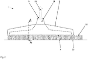
- FIG. 2 shows a floor nozzle 1 in a front view, ie from the view of the machining direction 5.
- the housing 3 of the floor nozzle 1 has a connecting piece 19, via which a vacuum cleaner 2 (FIG. Fig. 1 ) can be connected to the floor nozzle 1.
- a vacuum cleaner 2 FIG. Fig. 1
- FIG. 2 is a sectional plane AA in the machine direction 5 shown by the floor nozzle 1, which serves to explain in more detail below.
- FIG. 3 is a sectional view of a floor nozzle 1 shown, as is known in the prior art.
- the floor nozzle 1 is in a forward movement in the machining direction 5, ie the floor nozzle 1 is moved by the user in the illustration shown from right to left.
- the front suction mouth edge 7 of the suction mouth 6 located in the sliding sole 4 spreads the carpet fibers 32 on the floor surface 30 to be cleaned when the carpet pile passes over, so that adhering dirt particles 31 are ejected from the carpet fibers 32.
- the resulting by the ejection of the dirt particles 31 trajectory of the dirt particles 31 is indicated by dashed lines.
- FIG. 4 is a floor nozzle 1 according to the invention for a vacuum cleaner 2 ( Fig. 1 ) is shown in a perspective side view.
- the underside 4 of the floor nozzle 1 has an elongated suction mouth 6 running transversely to the machining direction 5.
- the suction mouth 6 represents an opening of the housing 3 in the suction mouth space 8 formed by the housing 3.
- the suction mouth 6 is provided with a suction channel 9 via the suction mouth space 8 (FIG. Fig. 5 ) connected by the blower of the Vacuum cleaner 2 ( Fig. 1 ) is conducted.
- the floor nozzle 2 via the connecting piece 19 with the suction pipe 26 (FIG. Fig. 1 ) connected.
- a partition wall 11a which separates a part of the suction mouth 8.
- a flow-through opening 12a through which the suction mouth 6 is fluidically connected to the suction channel 9 (FIG. Fig. 5 ) connected is.
- the suction mouth space wall has a specially shaped impact contour 15.
- a laterally arranged secondary air opening 14 can be seen, which has a suction air-independent partial air flow 34 (FIG. Fig. 8 ) to the suction channel 9 ( Fig. 5 ) generated.
- FIG. 5 shows schematically a floor nozzle 1 according to the invention FIG. 4 for a vacuum cleaner 2 ( Fig. 1 ) for cleaning and maintaining floor surfaces 30 ( Fig. 4 ) From a perspective side view in a sectional view.
- the suction mouth 8 in the housing 3 of the floor nozzle 1 is shown cut through the sectional view.
- At the rear suction mouth edge 7a of the suction mouth 6 there is a partition 11a which separates the suction mouth 6 from a dust collecting zone 10a in the suction mouth 8.
- the dust collecting zone 10a is formed by a collecting groove 13a, which is located below the throughflow opening 12a.
- the flow-through opening 12a forms as shown FIG. 5 can be seen, a connection of the suction 6 towards the suction channel 9.
- the formed below the flow-through opening 12a dust collection zone 10a extends, as shown FIG. 5
- the dust collecting zone 10a is arranged in the processing direction 5 behind the suction mouth 6, so that during a forward movement of the floor nozzle 1 in the machining direction 5 ejected from the front suction mouth edge 7 dirt particles 31 (FIGS. Fig. 6 ) in the dust collecting zone 10a behind the rear suction mouth 7a.
- the dirt particles 31 collected here ( Fig. 6 ) are transported away via the suction channel 9 formed by the connecting piece 19 from the dust collecting zone 10a.
- the described forward movement of the floor nozzle in the machining direction 5 is shown in the sectional view according to FIG FIG. 6 explained in more detail.
- FIG. 6 shows schematically a floor nozzle 1 according to the invention FIG. 4 for a vacuum cleaner 2 ( Fig. 1 ) for cleaning and maintaining floor surfaces 30 ( Fig. 4 ) From a side view in section according to the in FIG. 2 Plotted sectional plane AA.
- the sectional view shows that the floor nozzle 1 with the sliding sole of the underside 4 sweeps from right to left over the carpet fibers 32 in a forward movement in the machining direction 5.
- the carpet fibers 32 are bent from the front suction mouth edge 7 of the suction mouth 6 and adhering dirt particles 31 are according to the dashed trajectories from the carpet fibers 32nd spun.
- the suction mouth 8 has an impact contour 15 which promotes the dust collections in the dust collection zone 10a.
- the ejected dirt particles 31 bounce off the impact contour 15 and are simply conveyed through the flow-through opening 12a in the direction of the dust-collecting zone 10a.
- the dirt particles 31 dissolved by the bottom surface 30 accumulate by the forward movement of the suction mouth edge 7 and the rebound on the impact contour 15 in the dust collection zone 10a behind the suction mouth 6.
- the impact contour 15 is configured so that the dissolved dirt particles 31 usually impinge on the impact contour 15 in a certain angular range, wherein the accelerated by the ejection of the carpet fibers 32 dirt particles 31 usually bounce about the same angle of the impact contour 15 as they turn at the angle of incidence on the impact contour 15.
- the dust collecting zone 10a is arranged between the suction mouth 6 and the suction channel 9, so that dirt particles 31 collected in the dust collecting zone 10a can simply be transported away by the suction air stream 33 prevailing in the suction channel 9.
- the dust collecting zone 10a extending along the suction mouth 6 is separated from the suction mouth 6 by a partition wall 11a.
- a connection to the suction mouth 6 is given via the flow-through opening 12a in the partition wall 11a.
- the collecting channel 13a can be seen, by means of which the dust-collecting zone 10a is delimited and formed.
- FIG. 6 can also be clearly seen that the collecting channel 13a at the same time forms the rear suction mouth edge 7a.
- FIG. 6 a sectional plane BB drawn, which will be discussed below.
- FIG. 7 shows a further side view of the floor nozzle 1 in a sectional view.
- a secondary air opening 14a is associated with the dust collecting zone 10a arranged behind the suction mouth 6.
- This secondary air opening 14 a is independent of the suction part of the partial air flow 34 ( Fig. 8 ) Can be generated by the dust collection zone 10a towards the suction channel 9.
- This partial air flow 34 ( Fig. 8 ) dirt particles 31 collected in the dust collection zone 10a can be transported away very easily via the suction air flow 33 prevailing in the suction channel 9. Since the partial air flow 34 ( Fig.
- the removal of the collected dirt particles 31 from the dust collection zone 10 a is thus regularly, since the suction mouth 6 is often covered or clogged in particular by placing on long pile carpets, so that divided between the suction 6 and secondary air opening 14 a Saugluftstrom 33 of the suction channel 9, regularly to a higher proportion is diverted via the secondary air opening 14a.
- the arrangement of the secondary air opening 14a transversely to the machining direction 5 laterally in the housing 3 ensures that the partial air flow 34 (FIGS. Fig. 8 ) is reliably guided even with long-pile carpets of the secondary air opening 14a through the dust collection zone 10a.
- the lateral arrangement of the secondary air opening 14a in the vicinity of the bottom surface 30 also allows additional Kantenabsaugung through the secondary air opening 14a. As a result, carpet edges and floor surface area on baseboards can be effectively cleaned by the lateral secondary air opening 14a on the floor nozzle 1.
- FIG. 8 discloses a sectional view through the floor nozzle 1 according to the invention according to the in FIG. 6 Plotted sectional plane BB.
- the dirt particles 31 collected in the dust collecting zone 10a are, as can be seen from this illustration, transported away via the suction air flow 33 through the suction channel 8 of the connecting piece 19.
- the dust collecting zone 10a which extends along the elongated suction mouth 6, are associated with two lateral secondary air openings 14, 14a, via which two partial air flows 34 are conducted through the dust collecting zone 10a to the suction channel 9.
- the two partial air streams 34 are independent of the main air flow through the suction mouth 6 and serve mainly for the reliable removal of collected in the dust collection zone 10a dirt particles 31.
- FIG. 9 shows an embodiment of the invention, in which two Staubsammelzonen 10, 10 a are provided.
- One of the dust collecting zones 10 is located in the machining direction 5 in front of the suction mouth 6 and a dust collecting zone 10a is arranged behind the suction mouth 6 in the machining direction 5.
- the dust collecting zones 10, 10a each extend along the associated suction mouth edge 7, 7a of the suction mouth. They are each formed by a collecting channel 13, 13 a.
- the dust collecting zones 10, 10a can each have two secondary air openings 14, 14a (FIG. Fig. 8 ).
- Each of the two Dust collecting zones 10, 10a is separated from the suction mouth 6 by a dividing wall 11, 11a in the suction mouth 8.
- the suction channel 9 is divided in the example shown in two Operaaugkanäle 9a, 9b.
- floor nozzle 1 is in a forward movement in the machine direction 5, ie it is moved by the user from right to left, so that the sliding sole 4 slides over the carpet fibers 32 of the bottom surface 30.
- the carpet fibers are bent from the front suction mouth edge 7 of the suction 6 and adhering dirt particles 31 are ejected from the carpet fibers 32.
- the design of the impact contour 15 favors the dust collection in the rear dust collection zone 10a during the forward movement of the floor nozzle 1.
- the ejected dissolved dirt particles 31 bounce off the impact contour 15 in the direction of the rear dust collection zone 10 a, since the rebound angle essentially corresponds to the impact angle.
- the bounced dirt particles are collected in the rear dust collection zone 10a before being transported away via the suction air flow 33 in the suction channel 9.
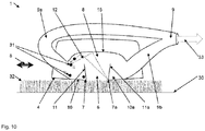
- FIG. 10 shows the floor nozzle 1 according to FIG. 9 in a backward movement in the machine direction 5.
- the movement initiated by the user causes the rear suction mouth edge 7a to bend the carpet fibers 32 swept over by the sliding sole 4, and adhering dirt particles 31 to be ejected from the carpet fibers 32.
- the ejected dirt particles 31 bounce off according to the dashed trajectory on the impact contour 15 of the suction mouth 8 and land in the dust collection zone 10, which extends along the front suction mouth edge 7 of the suction 6. From here, the collected dirt particles 31 are transported away via the Detailaugkanal 9b to the suction channel 9 out.
- the design of the floor nozzle 1 with two dust collection zones 10, 10a, wherein a dust collection zone 10 is located in the processing direction 5 in front of the suction mouth 6 and a dust collection zone 10a in the machine direction 5 behind the suction 6, has the advantage that dissolved dirt particles 31 both in a forward movement of the Floor nozzle 1 in the machine direction 5 and in a backward movement of the floor nozzle 1 in the machine direction 5 in the dust collection zones 10, 10 a are collected. As a result, a particularly effective and thorough cleaning of the bottom surface 30 is possible.
- the invention is not limited to the illustrated embodiments. Further embodiments are possible without departing from the basic idea.
- the floor nozzle 1 may also be formed as part of a self-propelled vacuum cleaner.
Landscapes
- Engineering & Computer Science (AREA)
- Mechanical Engineering (AREA)
- Nozzles For Electric Vacuum Cleaners (AREA)
Abstract
Description
- Die Erfindung betrifft eine Bodendüse für einen Staubsauger zur Reinigung und Pflege von Bodenflächen, mit einem Gehäuse, das eine in Bearbeitungsstellung der Bodenfläche zugewandte Unterseite aufweist, an der ein länglicher, quer zur Bearbeitungsrichtung verlaufender Saugmund angeordnet ist, wobei der Saugmund durch mindestens eine zugeordnete Saugmundkante begrenzt ist, wobei der Saugmund eine Öffnung zu einem in Bearbeitungsstellung über dem Saugmund angeordneten Saugmundraum bildet, wobei der Saugmundraum mit einem Saugkanal verbunden ist. Außerdem betrifft die Erfindung einen Staubsauger mit einer solchen Bodendüse.
- Im privaten Haushalt sowie im Gewerbe kommen Staubsauger zur Reinigung von Flächen wie textilen Bodenbelägen und glatten Böden zum Einsatz. Dabei wird zur Staubaufnahme eine Bodendüse des Staubsaugers auf einer Bodenfläche kontinuierlich vor- und zurückgeschoben. Die Staubaufnahmeeffektivität des Staubsaugers hängt dabei stark von der Gestaltung der Bodendüse ab. Im Rahmen der Reduzierung von Energieverbräuchen bei Staubsaugern spielt die Ausgestaltung der Bodendüse eine zunehmend wichtigere Rolle. Die Dimensionierung von Staubsaugergebläsen folgt einem Trend hin zu weniger Leistung, was erstmal zu geringeren, an der Bodendüse zur Verfügung stehenden, Volumenströmen führt, sodass sich aufgrund der Kontinuitätsbeziehung an den Bodendüsen in der Regel geringere Strömungsgeschwindigkeiten ergeben. Um dennoch ausreichend Staub aufzunehmen, werden die Bodendüsen insbesondere durch zusätzliche Lippen an den Saugmündern auf die geringeren Volumenströme angepasst.
- Aus der
DE 38 01 757 A1 ist eine Bodendüse für ein Bodenpflegegerät bekannt, wobei hier eine als schwenkbare Lippe ausgebildete Saugmundkante hinter dem Saugmund der Düse den Teppichflor beim Überstreichen aufspreizt, um den Teppich auch mit geringeren Volumenströmen tiefenwirksam reinigen zu können. Auch aus derEP 2 939 582 A1 ist eine Bodendüse mit als schwenkbare Lippen ausgebildeten sogenannten Saugmundkanten bekannt. - Nachteilig an den hier beschriebenen Lösungen ist, dass der Schiebewiderstand durch die Lippen erhöht wird. Je scharfkantiger die Lippen und Saugmundkanten ausgebildet werden, desto effektiver biegen sie den Teppichflor auf. Hierdurch wird allerdings der Schiebewiderstand auf der Bodenfläche derart erhöht, dass dies, insbesondere auf langflorigen Teppichen, zu einer unangenehmen und anstrengenden Handhabung des Staubsaugers und der Bodendüse für den Benutzer führt.
- Nachteilig an den hier beschriebenen Lösungen ist zudem, dass die von den Saugmundkanten gelösten Schmutzpartikel nur teilweise und damit ineffizient abgesaugt werden. Die durch die Saugmundkanten gelösten Schmutzpartikel werden gegen die Bewegungsrichtung der Saugmundkante gelöst und durch Absaugung nur teilweise aus dem Saugmundraum abtransportiert. Insbesondere bei der Bearbeitung von langflorigen Teppichen durch die Saugmundkanten werden Schmutzpartikel entgegen der Bewegungsrichtung der Saugmundkante durch zurückschnellende Teppichfasern ausgeworfen. Die ausgeworfenen Schmutzpartikel gelangen jedoch nur teilweise in den abtransportierenden Saugluftstrom, ein nicht unerheblicher Anteil der gelösten Schmutzpartikel wird nicht aus dem Saugmundraum abtransportiert, sondern landet zwangsläufig nach einem Abprallen an der Saugmundraumwand abermals auf der zu reinigenden Bodenfläche und wird wieder in die Teppichfaser eingearbeitet. Da hierdurch bereits gelöster Staub erneut mit der Bodenfläche in Kontakt gebracht wird und sich hier verfängt, ist eine effektive Staubaufnahme nicht gewährleistet. Bestenfalls wird der bereits gelöste Staub bei erneuter Bearbeitung der Bodenfläche durch die Saugmundkante erneut gelöst und von der Bodendüse aufgenommen. Allerdings sind hierdurch mehrfache Ablösungen der Schmutzpartikel aus den Teppichfasern nötig, so dass die Staubaufnahme nicht effektiv ist und so eine optimale Reinigung des Untergrundes nicht gewährleistet ist.
- Der Erfindung stellt sich somit das Problem, eine verbesserte Bodendüse und einen verbesserten Staubsauger anzugeben.
- Erfindungsgemäß wird dieses Problem durch eine Bodendüse mit den Merkmalen des Patentanspruchs 1 und einen Staubsauger gemäß Anspruch 12 gelöst. Dadurch, dass in dem Saugmundraum in Bearbeitungsrichtung vor dem Saugmund und / oder in Bearbeitungsrichtung hinter dem Saugmund eine Staubsammelzone angeordnet ist, kann die Bodendüse sehr effektiv gelöste Schmutzpartikel aufnehmen und so eine effektive Staubaufnahme, insbesondere auf Teppichen, gewährleisten. Hierdurch kann auch mit geringen Volumenströmen eine effektive Reinigung der Bodenfläche mit ausreichend hohen Strömungsgeschwindigkeiten erreicht werden. Mit einer solchen Bodendüse kann die Staubaufnahmeeffektivität - insbesondere auf Teppichböden - also vorteilhaft erhöht werden, sodass auch bei niedrigen Aufnahmeleistungen gute Performanceklassen bzw. Staubaufnahmewerte erreicht werden können. Die Staubaufnahmeeffektivität lässt sich hierdurch steigern, ohne dass es zu einer erheblichen Erhöhung der Schiebekräfte kommt. Außerdem kann der erforderliche Volumenstrom für eine effektive Reinigung weiter gesenkt werden, so dass sparsamere Gebläse im Staubsauger verbaut werden können. Die Verringerung der Volumenströme führt außerdem zu geringeren Strömungsverlusten, insbesondere bei beutellosen Abscheidern, sodass hier weiter Energie eingespart werden kann. Die Anordnung einer Staubsammelzone in Bearbeitungsrichtung vor oder hinter dem Saugmund verhindert eine Wiederanschmutzung der zu reinigenden Bodenfläche durch von der Saugraumwand zurückprallende Schmutzpartikel. Hierdurch ist eine Effizienzsteigerung im Abtransport bereits gelöster Schmutzpartikel erreichbar, da sich diese nach dem Lösen vor dem Abtransport durch den Saugluftstrom zunächst in der Staubsammelzone sammeln. Eine besonders effektive Staubaufnahme wird erreicht, wenn sich sowohl in Bearbeitungsrichtung vor dem Saugmund als auch in Bearbeitungsrichtung hinter dem Saugmund jeweils eine Staubsammelzone befindet. Hierdurch ist gewährleistet, dass durch die Saugmundkanten gelöste Schmutzpartikel sowohl in einer Vorwärtsbewegung der Bodendüse in Bearbeitungsrichtung als auch in einer Rückwärtsbewegung der Bodendüse in Bearbeitungsrichtung effektiv eingesammelt und über den vom Staubsaugergebläse erzeugten Saugluftstrom aus der Bodendüse abtransportiert werden.
- Die Bodenfläche kann durch einen textilen Bodenbelag wie einen Teppich oder Teppichboden oder durch einen Hartboden wie z. B. ein Holzparkett, Laminat oder einen PVC-Bodenbelag gebildet werden.
- Der Staubsauger kann ein Gebläse zur Erzeugung eines Unterdruckes aufweisen, durch den die über eine zu reinigende Bodenfläche geführte Bodendüse Staub und Schmutz von der Bodenfläche aufnimmt. Hierzu wird die Bodendüse durch den Benutzer mittels Schub- und Zugbewegungen in Bearbeitungsrichtung vor und zurück bewegt. Hierdurch gleitet die Bodendüse über die zu reinigende Bodenfläche. Insbesondere bei langflorigen Teppichen gleitet die Unterseite der Bodendüse über den Teppich, während die Unterseite bei Hartböden beabstandet, gegebenenfalls durch Abstandsborsten, über diese Bodenflächen hinweg schwebt. Der Benutzer kann dazu beispielsweise einen mit dem Saugrohr verbundenen Griff des Staubsaugers handhaben. Damit die Reinigung und Pflege des Bodenbelags möglichst effektiv ausgeführt werden kann, ist der Saugmund länglich ausgebildet und verläuft im Wesentlichen quer zur Bearbeitungsrichtung. Länglich ausgebildet bedeutet in diesem Zusammenhang, dass der vorzugsweise im Wesentlichen rechteckige Saugmund eine größere Länge quer zur Bearbeitungsrichtung aufweist, als Breite in Bearbeitungsrichtung. Der Saugmund ist vorzugsweise zwischen 20 und 30 cm quer zur Bearbeitungsrichtung lang und vorzugsweise zwischen einem und 3 cm in Bearbeitungsrichtung breit. Die Bodendüse kann auch an einem selbstständig fahrenden Staubsauger, insbesondere Saugroboter, angeordnet sein, sodass die Bearbeitungsrichtung der Bodendüse der Fahrtrichtung des selbstständig fahrenden Staubsaugers entspricht. Ein Staubsaugergehäuse des Staubsaugers kann eine Staubaufnahmekammer aufweisen, in welcher der über die Bodendüse aufgenommene Staub beispielsweise in einem Staubbeutel gesammelt werden kann.
- Vorteilhafte Ausgestaltungen und Weiterbildungen der Erfindung ergeben sich aus den nachfolgenden abhängigen Ansprüchen.
- Gemäß einer vorteilhaften Ausgestaltung der Erfindung ist vorgesehen, dass sich die Staubsammelzone entlang des Saugmundes erstreckt. Eine sich entlang des Staubsaugermundes erstreckende Staubsammelzone bietet eine effektive Möglichkeit, die von der Saugmund begrenzenden Saugmundkante gelösten Schmutzpartikel aufzusammeln. Erstreckt sich die Staubsammelzone im Wesentlichen über die gesamte Länge des Saugmundes ist eine besonders hohe Staubaufnahme durch die Bodendüse gewährleistet.
- Eine vorteilhafte Ausführung ist, dass die Staubsammelzone von dem Saugmund durch eine Trennwand im Saugmundraum abgetrennt ist. Die Abtrennung der Staubsammelzone durch eine Trennwand im Saugmundraum stellt sicher, dass gelöste und in der Staubsammelzone gesammelte Schmutzpartikel nicht wieder über den Saugmund aus der Bodendüse austreten können. Hierdurch wird eine erneute Anschmutzung der bereits gereinigten Bodenfläche durch die gelösten und gesammelten Schmutzpartikel verhindert.
- Eine bevorzugte Ausführung sieht vor, dass die Trennwand eine Durchströmöffnung aufweist, wobei die Durchströmöffnung den Saugmund strömungstechnisch mit dem Saugkanal verbindet. Die in der Trennwand angeordnete Durchströmöffnung stellt sicher, dass von der Bodenfläche gelöste Schmutzpartikel durch den Saugmund in die Staubsammelzone und über den Saugluftstrom in den Saugkanal gelangen, um effektiv aus der Bodendüse abtransportiert zu werden.
- Besonders vorteilhaft ist die Weiterbildung, dass in Bearbeitungsstellung unterhalb der Durchströmöffnung eine die Staubsammelzone bildende Sammelrinne angeordnet ist. Die Sammelrinne ist vorzugsweise als Verlängerung der im Saugmund angeordneten Trennwand ausgebildet. Die Begrenzung der Staubsammelzone durch eine Sammelrinne stellt sicher, dass bereits gelöste Schmutzpartikel zuverlässig in der Staubsammelzone gesammelt werden können, damit diese im Anschluss effektiv über den Saugkanal aus der Bodendüse abtransportiert werden können.
- Weiter vorteilhaft ist die Ausgestaltung, dass die Sammelrinne gleichzeitig die Saugmundkante bildet. Insbesondere dadurch, dass die Sammelrinne vorderseitig die Staubsammelzone umgrenzt und rückseitig die Saugmundkante bildet, ist eine besonders nahe Anordnung der Staubsammelzone an dem durch die Saugmundkante begrenzten Saugmund möglich. Hierdurch ist eine besonders hohe Staubaufnahme durch die Bodendüse und zuverlässige Staubsammlung in der Staubsammelzone möglich.
- Eine vorteilhafte Ausführungsform der Erfindung sieht vor, dass die Staubsammelzone zwischen Saugmund und Saugkanal angeordnet ist. Die Anordnung der Staubsammelzone zwischen dem Saugmund und dem Saugkanal stellt sicher, dass in der Staubsammelzone gesammelte Schmutzpartikel zuverlässig aus der Staubsammelzone über den Saugluftstrom durch den Saugkanal aus der Bodendüse abtransportiert werden.
- Gemäß einer vorteilhaften Ausgestaltung der Erfindung ist vorgesehen, dass der Staubsammelzone mindestens eine Nebenluftöffnung zugeordnet ist, die so angeordnet ist, dass ein vom Saugmund unabhängiger Teilluftstrom von der Nebenluftöffnung durch die Staubsammelzone hin zum Saugkanal erzeugbar ist. Die Anordnung einer Nebenluftöffnung im Bereich der Staubsammelzone stellt sicher, dass über den Teilluftstrom in der Staubsammelzone gesammelte Schmutzpartikel unabhängig vom Hauptluftstrom durch den Saugmund abtransportiert werden können. Dadurch, dass der Teilluftstrom durch die Nebenluftöffnung unabhängig vom Hauptluftstrom durch den Saugmund ist, kann ein Abtransport von gesammelten Schmutzpartikeln aus der Staubsammelzone auch bei einem verstopften oder abgedeckten Saugmund gewährleistet werden. Besonders effektiv ist der Abtransport von gesammelten Schmutzpartikeln aus der Staubsammelzone, wenn der Hauptluftstrom durch einen verstopften oder abgedeckten Saugmund vermindert ist und der Saugluftstrom am Saugkanal in diesem Fall zu einem größeren Teil über die Nebenluftöffnung umgeleitet wird. Hierdurch kann ein regelmäßiger Abtransport der gesammelten Schmutzpartikel aus der Staubsammelzone sichergestellt werden, da der Saugmund insbesondere durch das Aufsetzen auf langflorigen Teppichen regelmäßig abgedeckt bzw. verstopft wird, sodass der zwischen Saugmund und Nebenluftöffnung aufgeteilte Saugluftstrom des Saugkanals, regelmäßig zu einem größeren Teil über die Nebenluftöffnung umgeleitet wird.
- Eine bevorzugte Ausführung sieht vor, dass die mindestens eine Nebenluftöffnung quer zur Bearbeitungsrichtung seitlich im Gehäuse angeordnet ist. Die seitliche Anordnung der Nebenluftöffnung stellt sicher, dass der Teilluftstrom auch bei langflorigen Teppichen zuverlässig durch die Staubsammelzone geführt wird. Durch die seitliche Anordnung der Nebenluftöffnung in der Nähe der Bodenfläche kann zudem eine zusätzliche Kantenabsaugung durch die Nebenluftöffnung erreicht werden. Hierdurch lassen sich Bereiche nahe von Teppichkanten und Fußleisten effektiv durch die seitliche Nebenluftöffnung an der Bodendüse reinigen.
- Gemäß einer vorteilhaften Ausgestaltung der Erfindung ist vorgesehen, dass der Saugmundraum eine die Staubsammlung in der Staubsammelzone begünstigende Prallkontur aufweist. Eine solche Prallkontur stellt sicher, dass gelöste Schmutzpartikel zuverlässig in die Staubsammelzone gelangen und dort gesammelt werden.
- Eine vorteilhafte Ausführung ist, dass die Prallkontur so ausgebildet ist, dass durch die Saugmundkante von der Bodenfläche gelöste Schmutzpartikel an der Prallkontur in Richtung der Staubsammelzone abprallen. Bei der Ausgestaltung einer solchen Prallkontur ist zu beachten, dass die gelösten Schmutzpartikel in der Regel in einem gewissen Winkelbereich auf die Prallkontur auftreffen, wobei die durch den Auswurf aus Teppichfasern beschleunigten Schmutzpartikel in der Regel etwa in dem gleichen Ausfallswinkel von der Prallkontur abprallen, wie sie im Einfallswinkel auf die Prallkontur einschlagen. Durch die Erkenntnis, dass der Ausfallswinkel beim Abprallen von der Prallkontur im Wesentlichen dem Einfallswinkel beim Auftreffen auf die Prallkontur entspricht, lässt sich sehr einfach eine die Staubsammlung in der Staubsammelzone begünstigende Prallkontur im Saugmundraum ausbilden. Auf diese Weise lassen sich die Prallvorgänge der gelösten Schmutzpartikel auf der Prallkontur nutzen, um einen zuverlässigen Schmutzabtransport aus der Bodendüse zu gewährleisten und sicherzustellen, dass einmal gelöste Schmutzpartikel nicht wieder auf die Bodenfläche befördert werden.
- Ferner ist Gegenstand der Erfindung ein Staubsauger zur Reinigung und Pflege von Bodenflächen mit einem Gebläse zur Erzeugung eines Unterdruckes zur Aufnahme von Schmutz mittels eines Luftstromes und einem Abscheidesystem zur Reinigung der aufgenommenen Luft vom Schmutz, wobei der bereits und im Folgenden näher beschriebene Staubsauger eine Bodendüse gemäß der vorherigen und nachfolgenden Beschreibung aufweist.
- Weitere Merkmale, Einzelheiten und Vorteile der Erfindung ergeben sich aufgrund der nachfolgenden Beschreibung sowie anhand der Zeichnungen. Ausführungsbeispiele der Erfindung sind in den folgenden Zeichnungen rein schematisch dargestellt und werden nachfolgend näher beschrieben. Einander entsprechende Gegenstände oder Elemente sind in allen Figuren mit den gleichen Bezugszeichen versehen. Es zeigt
- Figur 1
- Erfindungsgemäßer Staubsauger mit Bodendüse,
- Figur 2
- Bodendüse in Frontansicht
- Figur 3
- Bodendüse in Schnittdarstellung
- Figur 4
- Erfindungsgemäße Bodendüse in perspektivischer Seitenansicht
- Figur 5
- Erfindungsgemäße Bodendüse in perspektivischer Schnittdarstellung
- Figur 6
- Erfindungsgemäße Bodendüse in Schnittdarstellung
- Figur 7
- Erfindungsgemäße Bodendüse in Schnittdarstellung
- Figur 8
- Erfindungsgemäße Bodendüse in Schnittdarstellung
- Figur 9
- Erfindungsgemäße Bodendüse in Schnittdarstellung
- Figur 10
- Erfindungsgemäße Bodendüse in Schnittdarstellung
- In den Figuren mit dem Bezugszeichen 1 bezeichnet ist eine erfindungsgemäße Bodendüse rein schematisch dargestellt. Die Darstellung gemäß
Figur 1 zeigt einen erfindungsgemäßen Staubsauger 2 mit einer an den Staubsauger 2 angeschlossenen Bodendüse 1. Bei dem im Ausführungsbeispiel dargestellten Staubsauger 1 handelt es sich um einen sogenannten Kanister-Staubsauger. Die Bodendüse 1 ist hier über ihren Anschlussstutzen 19 mit einem vorzugsweise teleskopierbar ausgestalteten Saugrohr 26 verbunden. Weiterhin weist die Bodendüse 1 bei diesem gezeigten Ausführungsbeispiel ein eigenes vom Staubsaugergehäuse 21, 21a unabhängiges Gehäuse 3 auf. Das teleskopierbare Saugrohr 26 geht in einen Handgriff 27 über, an dem ein Saugschlauch 16 angeschlossen ist, der mit dem Staubsaugergehäuse 21, 21a verbunden ist. Über ein elektrisches Anschlusskabel 22 wird ein in dem Staubsaugergehäuse 21, 21a integriertes (nicht gezeigtes) Gebläse des Staubsaugers 2 mit Strom betrieben, um einen Unterdruck zu erzeugen. Mittels dieses Unterdruckes werden Schmutz und Dreck von der zu reinigenden Bodenfläche 30 (Fig. 2 ,3 ,6 ,8 u. 9) durch einen Luftstrom über den Saugmund 6 (Fig. 4 ) der Bodendüse 1 aufgenommen und über das Saugrohr 26 und den Saugschlauch 16 in das Gehäuse 21, 21a des Staubsaugers 2 abtransportiert. In diesem Gehäuse 21, 21a vorgesehen ist ein Abscheidesystem 24, welches im Ausführungsbeispiel als Staubbeutel ausgebildet ist. Dieses Abscheidesystem 24 befindet sich in einem durch die Gehäuseteile 21 und 21a des Staubsaugers 2 gebildeten Staubraum 25. Dieser Staubraum 25 ist durch einen Klappmechanismus zwischen den Staubsaugergehäuseteilen 21 und 21a zugänglich und geöffnet dargestellt, sodass das Abscheidesystem 24 sichtbar und entnehmbar ist. Für den Betrieb des Staubsaugers 2 wird der Staubraum 25 geschlossen und ein Unterdruck erzeugt. Der durch den Unterdruck erzeugte Luftstrom wird in dem Abscheidesystem 24 von Schmutz und Dreck befreit und über ein Abluftgitter 23 aus dem Staubsauger 2 herausgeleitet. Zum Ein- und Ausschalten des Staubsaugers 2 weist dieser eine Trittschaltung 18 auf. Diese Trittschaltung 18 umfasst Schalter, die ausreichend groß sind, damit ein Benutzer diese mit dem Fuß betätigen kann. Die Trittschaltung 18 weist üblicherweise auch einen Schalter zur Betätigung der im Staubsaugergehäuse 21, 21a integrierten (nicht gezeigten) Wickelautomatik für das Anschlusskabel 22 auf. An dem Handgriff 27 befindet sich zudem eine Handschaltung 17, mit der Funktionen des Staubsaugers 2 aktiviert werden können. Außerdem kann der Staubsauger 2 über die Handschaltung 17 ein- und ausgeschaltet werden und es können Leistungsstufen des (nicht gezeigten) Gebläses ausgewählt werden. Ein Benutzer des Staubsaugers 1 kann diesen an dem Handgriff 27 ergreifen und so die Bodendüse 1 in einer mittels einer Schub- und Zugbewegung in der als Doppelpfeil gekennzeichneten Bearbeitungsrichtung 5 vor- und zurückschieben, um die Bodenfläche 30 (Fig. 2 ,3 ,6 ,8 u. 9) zu reinigen. Hierbei gleitet die Bodendüse 1 über die zu reinigende Bodenfläche 30 (Fig. 2 ,3 ,6 ,8 u. 9). Besonders bei langflorigen Teppichen gleitet die Unterseite 4 (Fig. 4 ) der Bodendüse 1 über die Bodenfläche 30 (Fig. 2 ,3 ,6 ,8 u. 9), während die Unterseite 4 (Fig. 2 ) bei Hartböden beabstandet, gegebenenfalls durch Abstandsborsten, über diese Bodenflächen 30 (Fig. 2 ,3 ,6 ,8 u. 9) hinweg schwebt. Im dargestellten Ausführungsbeispiel weist die Bodendüse 1 außerdem Abstützelemente 20 in Form von Rädern auf, welche einen definierten Abstand der Unterseite 4 (Fig. 4 ) zu den zu reinigenden Bodenflächen 30 (Fig. 2 ,3 ,6 ,8 u. 9) und eine einfache Handhabung beim Vor- und Zurückschieben der Bodendüse 1 sicherstellen. - Die
Figur 2 zeigt eine Bodendüse 1 in Frontansicht, d. h. aus Sicht der Bearbeitungsrichtung 5. Wie zu erkennen ist, liegt die als Gleitsohle ausgebildete Unterseite 4 auf den Teppichfasern 32 der Bodenfläche 30 auf. Das Gehäuse 3 der Bodendüse 1 weist einen Anschlussstutzen 19 auf, über den ein Staubsauger 2 (Fig. 1 ) mit der Bodendüse 1 verbunden werden kann. Durch den im Anschlussstutzen 19 gebildeten Saugkanal 9 wird dann der durch das Staubsaugergebläse des Staubsaugers 1 erzeugte Saugluftstrom 33 geleitet, wodurch von der Bodendüse 1 aufgenommene Schmutzpartikel 31 (Fig. 3 ) aus der Bodendüse 1 abtransportiert werden. InFigur 2 ist eine Schnittebene A-A in Bearbeitungsrichtung 5 durch die Bodendüse 1 gezeigt, die im Folgenden der näheren Erläuterung dient. - Gemäß
Figur 3 ist eine Schnittdarstellung einer Bodendüse 1 gezeigt, wie sie aus dem Stand der Technik bekannt ist. Die Bodendüse 1 befindet sich in einer Vorwärtsbewegung in Bearbeitungsrichtung 5, d. h. die Bodendüse 1 wird vom Benutzer in der gezeigten Darstellung von rechts nach links bewegt. Die vordere Saugmundkante 7 des in der Gleitsohle 4 befindlichen Saugmundes 6 spreizt beim Überstreichen des Teppichflors die Teppichfasern 32 auf der zu reinigenden Bodenfläche 30 auf, sodass anhaftende Schmutzpartikel 31 aus den Teppichfasern 32 ausgeworfen werden. Die durch den Auswurf der Schmutzpartikel 31 resultierende Trajektorie der Schmutzpartikel 31 ist gestrichelt angedeutet. An der beispielhaft eingezeichneten Flugbahn der Schmutzpartikel 31 ist zu erkennen, dass diese an der oberen Wand des Saugmundraumes 8 abprallen und vor der hinteren Saugmundkante 7a wieder auf die zu reinigende Bodenfläche 30 fallen, sodass sie von der hinteren Saugmundkante 7a wieder in die Teppichfasern 32 eingearbeitet werden. Durch diese erneute Wiederanschmutzung der bereits gereinigten Bodenfläche 30 ist eine effektive Staubaufnahme und zuverlässige Reinigung der Bodenfläche 30 nicht möglich. - In
Figur 4 ist eine erfindungsgemäße Bodendüse 1 für einen Staubsauger 2 (Fig. 1 ) in einer perspektivischen Seitenansicht gezeigt. Bei der hier dargestellten Ausführungsform weist die Unterseite 4 der Bodendüse 1 einen länglichen, quer zur Bearbeitungsrichtung 5 verlaufenden Saugmund 6 auf. Der Saugmund 6 stellt eine Öffnung des Gehäuses 3 in den von dem Gehäuse 3 gebildeten Saugmundraum 8 dar. Über den Saugmundraum 8 ist der Saugmund 6 mit einem Saugkanal 9 (Fig. 5 ) verbunden, durch den der von dem Gebläse des Staubsaugers 2 (Fig. 1 ) erzeugte Luftstrom geleitet wird. Hierzu wird die Bodendüse 2 über den Anschlussstutzen 19 mit dem Saugrohr 26 (Fig. 1 ) verbunden. Wie zu erkennen ist, befindet sich an der hinteren 7a der beiden den Saugmund 6 begrenzenden Saugmundkanten 7, 7a eine Trennwand 11a, die einen Teil des Saugmundraumes 8 abtrennt. Oberhalb der Trennwand 11a befindet sich eine Durchströmöffnung 12a, durch die der Saugmund 6 strömungstechnisch mit dem Saugkanal 9 (Fig. 5 ) verbunden ist. Weiterhin ist zu erkennen, dass die Saugmundraumwand eine speziell geformte Prallkontur 15 aufweist. Außerdem ist in dem Gehäuse 3 der Bodendüse 1 eine seitlich angeordnete Nebenluftöffnung 14 zu erkennen, die einen vom Saugmund unabhängigen Teilluftstrom 34 (Fig. 8 ) hin zum Saugkanal 9 (Fig. 5 ) erzeugt. - Die
Figur 5 zeigt schematisch eine erfindungsgemäße Bodendüse 1 gemäßFigur 4 für einen Staubsauger 2 (Fig. 1 ) zur Reinigung und Pflege von Bodenflächen 30 (Fig. 4 ) aus einer perspektivischen Seitenansicht in Schnittdarstellung. Der Saugmundraum 8 im Gehäuse 3 der Bodendüse 1 ist durch die Schnittdarstellung aufgeschnitten dargestellt. An der hinteren Saugmundkante 7a des Saugmundes 6 befindet sich eine Trennwand 11a, die den Saugmund 6 von einer Staubsammelzone 10a im Saugmundraum 8 abtrennt. Die Staubsammelzone 10a ist durch eine Sammelrinne 13a gebildet, welche sich unterhalb der Durchströmöffnung 12a befindet. Die Durchströmöffnung 12a bildet, wie ausFigur 5 ersichtlich, eine Verbindung des Saugmundes 6 hin zum Saugkanal 9. Die unterhalb der Durchströmöffnung 12a gebildete Staubsammelzone 10a erstreckt sich, wie ausFigur 5 gut zu erkennen, quer zur Bearbeitungsrichtung 5 entlang des länglichen Saugmundes 6. Die Staubsammelzone 10a ist in Bearbeitungsrichtung 5 hinter dem Saugmund 6 angeordnet, sodass sich bei einer Vorwärtsbewegung der Bodendüse 1 in Bearbeitungsrichtung 5 von der vorderen Saugmundkante 7 ausgeworfene Schmutzpartikel 31 (Fig. 6 ) in der Staubsammelzone 10a hinter der hinteren Saugmundkante 7a sammeln. Die hier gesammelten Schmutzpartikel 31 (Fig. 6 ) werden über den durch den Anschlussstutzen 19 gebildeten Saugkanal 9 aus der Staubsammelzone 10a abtransportiert. Die beschriebene Vorwärtsbewegung der Bodendüse in Bearbeitungsrichtung 5 ist in der Schnittdarstellung gemäßFigur 6 näher erläutert. - Die
Figur 6 zeigt schematisch eine erfindungsgemäße Bodendüse 1 gemäßFigur 4 für einen Staubsauger 2 (Fig. 1 ) zur Reinigung und Pflege von Bodenflächen 30 (Fig. 4 ) aus einer Seitenansicht in Schnittdarstellung gemäß der inFigur 2 eingezeichneten Schnittebene A-A. Die Schnittdarstellung zeigt, dass die Bodendüse 1 mit der Gleitsohle der Unterseite 4 von rechts nach links über die Teppichfasern 32 in einer Vorwärtsbewegung in Bearbeitungsrichtung 5 streicht. Hierdurch werden die Teppichfasern 32 von der vorderen Saugmundkante 7 des Saugmunds 6 aufgebogen und anhaftende Schmutzpartikel 31 werden gemäß der gestrichelt eingezeichneten Flugbahnen aus den Teppichfasern 32 geschleudert. Der Saugmundraum 8 weist eine die Staubsammlungen in der Staubsammelzone 10a begünstigende Prallkontur 15 auf. Hierdurch prallen die ausgeworfenen Schmutzpartikel 31 an der Prallkontur 15 ab und werden einfach durch die Durchströmöffnung 12a in Richtung der Staubsammelzone 10a befördert. Auf diese Weise sammeln sich die von der Bodenfläche 30 gelösten Schmutzpartikel 31 durch die Vorwärtsbewegung der Saugmundkante 7 und das Abprallen an der Prallkontur 15 in der Staubsammelzone 10a hinter dem Saugmund 6. Wie zu erkennen, ist die Prallkontur 15 so ausgestaltet, dass die gelösten Schmutzpartikel 31 in der Regel in einem gewissen Winkelbereich auf die Prallkontur 15 auftreffen, wobei die durch den Auswurf aus den Teppichfasern 32 beschleunigten Schmutzpartikel 31 in der Regel etwa in dem gleichen Ausfallswinkel von der Prallkontur 15 abprallen, wie sie im Einfallswinkel auf die Prallkontur 15 einschlagen. Aufgrund der Gegebenheit, dass der Ausfallswinkel der Schmutzpartikel 31 beim Abprallen von der Prallkontur 15 im Wesentlichen dem Einfallswinkel beim Auftreffen der Schmutzpartikel 21 auf die Prallkontur 15 entspricht, lässt sich sehr einfach eine die Staubsammlung in der Staubsammelzone 10a begünstigende Prallkontur 15 im Saugmundraum 8 ausbilden. Hierdurch lassen sich die Prallvorgänge der gelösten Schmutzpartikel 31 auf der Prallkontur 15 nutzen, um einen zuverlässigen Schmutzabtransport aus der Bodendüse 1 zu gewährleisten und um sicherzustellen, dass einmal gelöste Schmutzpartikel 31 nicht wieder auf die Bodenfläche 30 befördert werden. Die Staubsammelzone 10a ist zwischen dem Saugmund 6 und dem Saugkanal 9 angeordnet, sodass in der Staubsammelzone 10a gesammelte Schmutzpartikel 31 einfach durch den im Saugkanal 9 herrschenden Saugluftstrom 33 abtransportiert werden können. Die sich entlang des Saugmundes 6 erstreckende Staubsammelzone 10a ist durch eine Trennwand 11a gegenüber dem Saugmund 6 abgetrennt. Eine Verbindung zum Saugmund 6 ist über die Durchströmöffnung 12a in der Trennwand 11a gegeben. Unterhalb der Durchströmöffnung 12a ist die Sammelrinne 13a zu erkennen, durch welche die Staubsammelzone 10a begrenzt und gebildet ist. AusFigur 6 lässt sich auch gut erkennen, dass die Sammelrinne 13a zugleich die hintere Saugmundkante 7a bildet. Zur näheren Erläuterung ist inFigur 6 eine Schnittebene B-B eingezeichnet, auf die im Folgenden eingegangen wird. - Die
Figur 7 zeigt eine weitere Seitenansicht der Bodendüse 1 in Schnittdarstellung. In dieser Schnittdarstellung ist gut zu erkennen, dass eine Nebenluftöffnung 14a der hinter dem Saugmund 6 angeordneten Staubsammelzone 10a zugeordnet ist. Über diese Nebenluftöffnung 14a ist ein vom Saugmund unabhängiger Teilluftstrom 34 (Fig. 8 ) durch die Staubsammelzone 10a hin zum Saugkanal 9 erzeugbar. Über diesen Teilluftstrom 34 (Fig. 8 ) lassen sich in der Staubsammelzone 10a gesammelte Schmutzpartikel 31 sehr einfach über den im Saugkanal 9 herrschenden Saugluftstrom 33 abtransportieren. Da der Teilluftstrom 34 (Fig. 8 ) durch die Nebenluftöffnung 14a unabhängig vom Hauptluftstrom durch den Saugmund 6 ist, kann ein Abtransport von gesammelten Schmutzpartikeln 31 aus der Staubsammelzone 10a auch bei einem verstopften oder abgedeckten Saugmund 6 gewährleistet werden. Der Abtransport von gesammelten Schmutzpartikeln 31 aus der Staubsammelzone 10a funktioniert besonders zuverlässig, wenn der Hauptluftstrom durch einen verstopften oder abgedeckten Saugmund 6 reduziert ist und der am Saugkanal 9 anliegende Saugluftstrom 33 in diesem Fall zu einem größeren Teil über die Nebenluftöffnung 14a umgeleitet wird. Der Abtransport der gesammelten Schmutzpartikel 31 aus der Staubsammelzone 10a erfolgt somit regelmäßig, da der Saugmund 6 insbesondere durch das Aufsetzen auf langflorigen Teppichen häufig abgedeckt bzw. verstopft wird, sodass der zwischen Saugmund 6 und Nebenluftöffnung 14a aufgeteilte Saugluftstrom 33 des Saugkanals 9, regelmäßig zu einem höheren Anteil über die Nebenluftöffnung 14a umgeleitet wird. Die Anordnung der Nebenluftöffnung 14a quer zur Bearbeitungsrichtung 5 seitlich im Gehäuse 3 stellt sicher, dass der Teilluftstrom 34 (Fig. 8 ) auch bei langflorigen Teppichen zuverlässig von der Nebenluftöffnung 14a durch die Staubsammelzone 10a geführt wird. Die seitliche Anordnung der Nebenluftöffnung 14a in der Nähe der Bodenfläche 30 ermöglicht außerdem eine zusätzliche Kantenabsaugung durch die Nebenluftöffnung 14a. Dadurch lassen sich Teppichkanten und Bodenflächenbereich an Fußleisten effektiv durch die seitliche Nebenluftöffnung 14a an der Bodendüse 1 reinigen. -
Figur 8 offenbart eine Schnittdarstellung durch die erfindungsgemäße Bodendüse 1 gemäß der inFigur 6 eingezeichneten Schnittebene B-B. Die in der Staubsammelzone 10a gesammelten Schmutzpartikel 31 werden, wie aus dieser Darstellung ersichtlich, über den Saugluftstrom 33 durch den Saugkanal 8 des Anschlussstutzens 19 abtransportiert. Der Staubsammelzone 10a, die sich entlang des länglichen Saugmundes 6 erstreckt, sind zwei seitliche Nebenluftöffnungen 14, 14a zugeordnet, über welche zwei Teilluftströmungen 34 durch die Staubsammelzone 10a hin zum Saugkanal 9 geleitet werden. Die beiden Teilluftströme 34 sind unabhängig von dem Hauptluftstrom durch den Saugmund 6 und dienen hauptsächlich dem zuverlässigen Abtransport der in der Staubsammelzone 10a gesammelten Schmutzpartikel 31. Durch die Anordnung von zwei seitlichen Nebenluftöffnungen 34 kann die sich entlang des Saugmundes 6 erstreckende Staubsammelzone 10a zuverlässig durch die Teilluftströme 34 von gesammelten Schmutzpartikeln 31 befreit werden. - Aus
Figur 9 geht eine erfindungsgemäße Ausführungsform hervor, bei der zwei Staubsammelzonen 10, 10a vorgesehen sind. Eine der Staubsammelzonen 10 ist in Bearbeitungsrichtung 5 vor dem Saugmund 6 und eine Staubsammelzone 10a ist in Bearbeitungsrichtung 5 hinter dem Saugmund 6 angeordnet. Die Staubsammelzonen 10, 10a erstrecken sich jeweils entlang der zugeordneten Saugmundkante 7, 7a des Saugmundes. Sie sind jeweils durch eine Sammelrinne 13, 13a gebildet. Den Staubsammelzonen 10, 10a können jeweils zwei Nebenluftöffnungen 14, 14a (Fig. 8 )zugeordnet sein. Jede der beiden Staubsammelzonen 10, 10a ist durch eine Trennwand 11, 11a im Saugmundraum 8 von dem Saugmund 6 abgetrennt. Oberhalb der Trennwände 11, 11a sind Durchströmöffnungen 12, 12a vorgesehen, die jeweils eine Strömungsverbindung zwischen dem Saugmund 6 und dem Saugkanal 9 herstellen. Der Saugkanal 9 ist in dem dargestellten Beispiel in zwei Teilsaugkanäle 9a, 9b aufgeteilt. Hierdurch ist ein Abtransport gesammelter Schmutzpartikel 31 aus beiden Staubsammelzonen 10, 10a gewährleistet. Die inFigur 9 schematisch dargestellte Bodendüse 1 befindet sich in einer Vorwärtsbewegung in Bearbeitungsrichtung 5, d. h. sie wird vom Benutzer von rechts nach links bewegt, sodass die Gleitsohle 4 über die Teppichfasern 32 der Bodenfläche 30 gleitet. Hierbei werden die Teppichfasern von der vorderen Saugmundkante 7 des Saugmundes 6 aufgebogen und anhaftende Schmutzpartikel 31 werden aus den Teppichfasern 32 herausgeschleudert. Die herausgeschleuderten Schmutzpartikel 31 fliegen hierdurch gemäß der strichpunktiert dargestellten Flugbahnen gegen die im Saugmundraum 8 angeordnete Prallkontur 15. Wie zu erkennen ist, begünstigt die Ausgestaltung der Prallkontur 15 die Staubsammlung in der hinteren Staubsammelzone 10a bei der Vorwärtsbewegung der Bodendüse 1. Die von der vorderen Saugmundkante gelösten Schmutzpartikel 31 prallen an der Prallkontur 15 in Richtung der hinteren Staubsammelzone 10a ab, da der Abprallwinkel dem Anprallwinkel im Wesentlichen entspricht. Die abgeprallten Schmutzpartikel werden in der hinteren Staubsammelzone 10a gesammelt, bevor sie über den Saugluftstrom 33 im Saugkanal 9 abtransportiert werden. - Die
Figur 10 zeigt die Bodendüse 1 gemäßFigur 9 in einer Rückwärtsbewegung in Bearbeitungsrichtung 5. Die durch den Benutzer eingeleitete Bewegung führt dazu, dass die hintere Saugmundkante 7a die von der Gleitsohle 4 überstrichenen Teppichfasern 32 aufbiegt und anhaftende Schmutzpartikel 31 aus den Teppichfasern 32 herausgeschleudert werden. Die herausgeschleuderten Schmutzpartikel 31 prallen gemäß der gestrichelt eingezeichneten Flugbahn an der Prallkontur 15 des Saugmundraumes 8 ab und landen in der Staubsammelzone 10, die sich entlang der vorderen Saugmundkante 7 des Saugmundes 6 erstreckt. Von hier aus werden die gesammelten Schmutzpartikel 31 über den Teilsaugkanal 9b zum Saugkanal 9 hin abtransportiert. Die Ausgestaltung der Bodendüse 1 mit zwei Staubsammelzonen 10, 10a, wobei sich eine Staubsammelzone 10 in Bearbeitungsrichtung 5 vor dem Saugmund 6 und eine Staubsammelzone 10a in Bearbeitungsrichtung 5 hinter dem Saugmund 6 befindet, hat den Vorteil, dass gelöste Schmutzpartikel 31 sowohl in einer Vorwärtsbewegung der Bodendüse 1 in Bearbeitungsrichtung 5 als auch in einer Rückwärtsbewegung der Bodendüse 1 in Bearbeitungsrichtung 5 in den Staubsammelzonen 10, 10a gesammelt werden. Hierdurch ist eine besonders effektive und gründliche Reinigung der Bodenfläche 30 möglich. - Natürlich ist die Erfindung nicht auf die dargestellten Ausführungsbeispiele beschränkt. Weitere Ausgestaltungen sind möglich, ohne den Grundgedanken zu verlassen. So kann die Bodendüse 1 auch als Teil eines selbstfahrenden Staubsaugers ausgebildet sein.
-
- 1 Bodendüse
- 2 Staubsauger
- 3 Gehäuse
- 4 Unterseite (Gleitsohle)
- 5 Bearbeitungsrichtung
- 6 Saugmund
- 7 7a Saugmundkante
- 8 Saugmundraum
- 9 Saugkanal, 9a, 9b Teilsaugkanäle
- 10 10a Staubsammelzone
- 11 11a Trennwand
- 12 12a Durchströmöffnung
- 13 13a Sammelrinne
- 14 14a Nebenluftöffnung
- 15 Prallkontur
- 16 Saugschlauch
- 17 Handschaltung
- 18 Trittschaltung
- 19 Anschlussstutzen
- 20 Abstützelemente
- 21 21a Staubsaugergehäuse, Staubsaugergehäuseteile
- 22 Anschlusskabel
- 23 Abluftgitter
- 24 Abscheidesystem
- 25 Staubraum
- 26 Saugrohr
- 27 Handgriff
- 30 Bodenfläche
- 31 Schmutzpartikel
- 32 Teppichfasern
- 33 Saugluftstrom
- 34 Teilluftstrom
Claims (12)
- Bodendüse (1) für einen Staubsauger (2) zur Reinigung und Pflege von Bodenflächen (30), mit einem Gehäuse (3), das eine in Bearbeitungsstellung der Bodenfläche (30) zugewandte Unterseite (4) aufweist, an der ein im Wesentlichen quer zur Bearbeitungsrichtung (5) verlaufender Saugmund (6) angeordnet ist, wobei der Saugmund (6) durch mindestens eine zugeordnete Saugmundkante (7, 7a) begrenzt ist, wobei der Saugmund (6) eine Öffnung zu einem in Bearbeitungsstellung über dem Saugmund (6) angeordneten Saugmundraum (8) bildet, wobei der Saugmundraum (8) mit einem Saugkanal (9) verbunden ist,
dadurch gekennzeichnet,
dass in dem Saugmundraum (8) in Bearbeitungsrichtung (5) vor dem Saugmund (6) und / oder in Bearbeitungsrichtung (5) hinter dem Saugmund (6) eine Staubsammelzone (10, 10a) angeordnet ist. - Bodendüse (1) nach Anspruch 1, dadurch gekennzeichnet, dass sich die Staubsammelzone (10, 10a) entlang des Saugmundes (6) erstreckt.
- Bodendüse (1) nach Anspruch 1 oder 2, dadurch gekennzeichnet, dass die Staubsammelzone (10, 10a) von dem Saugmund (6) durch eine Trennwand (11, 11a) im Saugmundraum (8) abgetrennt ist.
- Bodendüse (1) nach Anspruch 3, dadurch gekennzeichnet, dass die Trennwand (11, 11a) eine Durchströmöffnung (12, 12a) aufweist, wobei die Durchströmöffnung (12, 12a) den Saugmund (6) strömungstechnisch mit dem Saugkanal (9) verbindet.
- Bodendüse (1) nach Anspruch 4, dadurch gekennzeichnet, dass in Bearbeitungsstellung unterhalb der Durchströmöffnung (12, 12a) eine die Staubsammelzone (10, 10a) bildende Sammelrinne (13, 13a) angeordnet ist.
- Bodendüse (1) nach Anspruch 5, dadurch gekennzeichnet, dass die Sammelrinne (13, 13a) die Saugmundkante (7, 7a) bildet.
- Bodendüse (1) nach einem der Ansprüche 1 bis 6, dadurch gekennzeichnet, dass die Staubsammelzone (10, 10a) zwischen Saugmund (6) und Saugkanal (9) angeordnet ist.
- Bodendüse (1) nach einem der Ansprüche 1 bis 7, dadurch gekennzeichnet, dass der Staubsammelzone (10, 10a) mindestens eine Nebenluftöffnung (14, 14a) zugeordnet ist, die so angeordnet ist, dass ein vom Saugmund (7) unabhängiger Teilluftstrom von der Nebenluftöffnung (14, 14a) durch die Staubsammelzone (10, 10a) hin zum Saugkanal (9) erzeugbar ist.
- Bodendüse (1) nach einem der Ansprüche 1 bis 8, dadurch gekennzeichnet, dass die mindestens eine Nebenluftöffnung (14, 14a) quer zur Bearbeitungsrichtung (5) seitlich im Gehäuse (3) angeordnet ist.
- Bodendüse (1) nach einem der Ansprüche 1 bis 9, dadurch gekennzeichnet, dass der Saugmundraum (8) eine die Staubsammlung in der Staubsammelzone (10, 10a) begünstigende Prallkontur (15) aufweist.
- Bodendüse (1) nach Anspruch 10, dadurch gekennzeichnet, dass die Prallkontur (15) so ausgebildet ist, dass durch die Saugmundkante (7, 7a) von der Bodenfläche (30) gelöste Schmutzpartikel (31) an der Prallkontur (15) in Richtung der Staubsammelzone (10, 10a) abprallen.
- Staubsauger (2) zur Reinigung und Pflege von Bodenflächen (30) mit einem Gebläse zur Erzeugung eines Unterdruckes zur Aufnahme von Schmutz mittels eines Luftstromes und einem Abscheidesystem (24) zur Reinigung der aufgenommenen Luft vom Schmutz, gekennzeichnet durch eine Bodendüse (1) nach einem der vorhergehenden Ansprüche.
Applications Claiming Priority (1)
| Application Number | Priority Date | Filing Date | Title |
|---|---|---|---|
| DE102017114163.4A DE102017114163A1 (de) | 2017-06-27 | 2017-06-27 | Bodendüse für Staubsauger und Staubsauger |
Publications (2)
| Publication Number | Publication Date |
|---|---|
| EP3420872A1 true EP3420872A1 (de) | 2019-01-02 |
| EP3420872B1 EP3420872B1 (de) | 2021-07-07 |
Family
ID=62528344
Family Applications (1)
| Application Number | Title | Priority Date | Filing Date |
|---|---|---|---|
| EP18175780.8A Active EP3420872B1 (de) | 2017-06-27 | 2018-06-04 | Bodendüse für staubsauger und staubsauger |
Country Status (2)
| Country | Link |
|---|---|
| EP (1) | EP3420872B1 (de) |
| DE (1) | DE102017114163A1 (de) |
Cited By (1)
| Publication number | Priority date | Publication date | Assignee | Title |
|---|---|---|---|---|
| EP3795047A1 (de) * | 2019-09-23 | 2021-03-24 | Wessel-Werk GmbH | Universalstaubsaugerbodendüse |
Citations (4)
| Publication number | Priority date | Publication date | Assignee | Title |
|---|---|---|---|---|
| JPH047038U (de) * | 1990-05-07 | 1992-01-22 | ||
| DE19914574C1 (de) * | 1999-03-31 | 2000-11-23 | Duepro Ag Romanshorn | Reinigungsgerät |
| EP1525839A2 (de) * | 2003-10-23 | 2005-04-27 | Polar Light Limited | Schmutzbehälter für ein Bodenreinigungsgerät und Verfahren zur Verwendung desselben |
| US20060195991A1 (en) * | 2004-05-11 | 2006-09-07 | Baumhakel Alexander J | Transport cleaning device |
Family Cites Families (4)
| Publication number | Priority date | Publication date | Assignee | Title |
|---|---|---|---|---|
| DE3801757A1 (de) | 1988-01-22 | 1989-07-27 | Wessel Werk Gmbh | Staubsaugerduese |
| GB2530933B (en) * | 2013-11-25 | 2017-06-07 | Hoover Ltd | Vacuum cleaner head |
| DE102014105756A1 (de) * | 2014-04-24 | 2015-10-29 | Miele & Cie. Kg | Bodenpflegegerät mit einer Abluftrückführung |
| DE102014208080A1 (de) | 2014-04-29 | 2015-10-29 | BSH Hausgeräte GmbH | Staubsaugerdüse |
-
2017
- 2017-06-27 DE DE102017114163.4A patent/DE102017114163A1/de not_active Withdrawn
-
2018
- 2018-06-04 EP EP18175780.8A patent/EP3420872B1/de active Active
Patent Citations (4)
| Publication number | Priority date | Publication date | Assignee | Title |
|---|---|---|---|---|
| JPH047038U (de) * | 1990-05-07 | 1992-01-22 | ||
| DE19914574C1 (de) * | 1999-03-31 | 2000-11-23 | Duepro Ag Romanshorn | Reinigungsgerät |
| EP1525839A2 (de) * | 2003-10-23 | 2005-04-27 | Polar Light Limited | Schmutzbehälter für ein Bodenreinigungsgerät und Verfahren zur Verwendung desselben |
| US20060195991A1 (en) * | 2004-05-11 | 2006-09-07 | Baumhakel Alexander J | Transport cleaning device |
Cited By (1)
| Publication number | Priority date | Publication date | Assignee | Title |
|---|---|---|---|---|
| EP3795047A1 (de) * | 2019-09-23 | 2021-03-24 | Wessel-Werk GmbH | Universalstaubsaugerbodendüse |
Also Published As
| Publication number | Publication date |
|---|---|
| DE102017114163A1 (de) | 2018-12-27 |
| EP3420872B1 (de) | 2021-07-07 |
Similar Documents
| Publication | Publication Date | Title |
|---|---|---|
| EP2866631B1 (de) | Kombination aus einem kleinsauger und einem staubsaugergehäuse sowie kleinsauger und staubsaugergehäuse | |
| DE10316083A1 (de) | Kantenreinigungssystem für Vakuumreiniger | |
| WO2016202610A1 (de) | Saugdüse für einen staubsauger | |
| DE102012104706B4 (de) | Saugdüse mit zwei Saugmündern | |
| DE69119113T2 (de) | Sammelvorrichtung | |
| EP3417750A1 (de) | Bodendüse für staubsauger und staubsauger | |
| DE102014117418A1 (de) | Bodendüse für ein Bodenpflegegerät und Verfahren zum Herstellen einer Bodendüse für ein Bodenpflegegerät | |
| EP2866632B1 (de) | Kombination aus einem kleinsauger und einem stielsaugerrahmen sowie kleinsauger und stielsaugerrahmen | |
| DE102008030707B4 (de) | Staubsammelkammer sowie Verfahren zum Betrieb einer Staubsammelkammer | |
| EP3420872B1 (de) | Bodendüse für staubsauger und staubsauger | |
| DE102015108157A1 (de) | Saugdüse für einen Staubsauger | |
| EP3586709B1 (de) | Bodendüse für staubsauger und staubsauger | |
| EP3984429A1 (de) | Staubsauger und verfahren zum betrieb eines staubsaugers | |
| DE102017114181A1 (de) | Bodendüse für Staubsauger und Staubsauger | |
| EP2534991B1 (de) | Bodendüse für einen Staubsauger und Staubsauger mit einer solchen Bodendüse | |
| DE102008020314A1 (de) | Elektromotorisch betriebener, verfahrbarer Staubsauger | |
| EP3446610B1 (de) | Staubsauger und verfahren zum betrieb eines staubsaugers | |
| DE102018131547A1 (de) | Saugdüse für Staubsauger und Staubsauger sowie Verfahren zur Herstellung einer Saugdüse | |
| DE102017100253A1 (de) | Bodendüse für Staubsauger und Staubsauger | |
| DE102012223337B4 (de) | Trichterförmige Bodendüse mit Zyklon-Saugmund | |
| EP3298944B1 (de) | Bodendüse für staubsauger und staubsauger | |
| DE102016122456A1 (de) | Bodendüse für Staubsauger und Staubsauger | |
| EP2659820B1 (de) | Filterkassette für einen Staubsauger | |
| DE102017114064A1 (de) | Bodendüse für Staubsauger und Staubsauger | |
| EP3345523A1 (de) | Bodendüse für staubsauger und staubsauger |
Legal Events
| Date | Code | Title | Description |
|---|---|---|---|
| PUAI | Public reference made under article 153(3) epc to a published international application that has entered the european phase |
Free format text: ORIGINAL CODE: 0009012 |
|
| STAA | Information on the status of an ep patent application or granted ep patent |
Free format text: STATUS: THE APPLICATION HAS BEEN PUBLISHED |
|
| STAA | Information on the status of an ep patent application or granted ep patent |
Free format text: STATUS: REQUEST FOR EXAMINATION WAS MADE |
|
| AK | Designated contracting states |
Kind code of ref document: A1 Designated state(s): AL AT BE BG CH CY CZ DE DK EE ES FI FR GB GR HR HU IE IS IT LI LT LU LV MC MK MT NL NO PL PT RO RS SE SI SK SM TR |
|
| AX | Request for extension of the european patent |
Extension state: BA ME |
|
| 17P | Request for examination filed |
Effective date: 20181210 |
|
| RBV | Designated contracting states (corrected) |
Designated state(s): AL AT BE BG CH CY CZ DE DK EE ES FI FR GB GR HR HU IE IS IT LI LT LU LV MC MK MT NL NO PL PT RO RS SE SI SK SM TR |
|
| GRAP | Despatch of communication of intention to grant a patent |
Free format text: ORIGINAL CODE: EPIDOSNIGR1 |
|
| STAA | Information on the status of an ep patent application or granted ep patent |
Free format text: STATUS: GRANT OF PATENT IS INTENDED |
|
| INTG | Intention to grant announced |
Effective date: 20210331 |
|
| GRAS | Grant fee paid |
Free format text: ORIGINAL CODE: EPIDOSNIGR3 |
|
| GRAA | (expected) grant |
Free format text: ORIGINAL CODE: 0009210 |
|
| STAA | Information on the status of an ep patent application or granted ep patent |
Free format text: STATUS: THE PATENT HAS BEEN GRANTED |
|
| REG | Reference to a national code |
Ref country code: DE Ref legal event code: R084 Ref document number: 502018005980 Country of ref document: DE |
|
| AK | Designated contracting states |
Kind code of ref document: B1 Designated state(s): AL AT BE BG CH CY CZ DE DK EE ES FI FR GB GR HR HU IE IS IT LI LT LU LV MC MK MT NL NO PL PT RO RS SE SI SK SM TR |
|
| REG | Reference to a national code |
Ref country code: GB Ref legal event code: FG4D Free format text: NOT ENGLISH |
|
| REG | Reference to a national code |
Ref country code: AT Ref legal event code: REF Ref document number: 1407733 Country of ref document: AT Kind code of ref document: T Effective date: 20210715 |
|
| REG | Reference to a national code |
Ref country code: DE Ref legal event code: R096 Ref document number: 502018005980 Country of ref document: DE |
|
| REG | Reference to a national code |
Ref country code: IE Ref legal event code: FG4D Free format text: LANGUAGE OF EP DOCUMENT: GERMAN |
|
| REG | Reference to a national code |
Ref country code: GB Ref legal event code: 746 Effective date: 20210721 |
|
| REG | Reference to a national code |
Ref country code: LT Ref legal event code: MG9D |
|
| REG | Reference to a national code |
Ref country code: NL Ref legal event code: MP Effective date: 20210707 |
|
| PG25 | Lapsed in a contracting state [announced via postgrant information from national office to epo] |
Ref country code: RS Free format text: LAPSE BECAUSE OF FAILURE TO SUBMIT A TRANSLATION OF THE DESCRIPTION OR TO PAY THE FEE WITHIN THE PRESCRIBED TIME-LIMIT Effective date: 20210707 Ref country code: SE Free format text: LAPSE BECAUSE OF FAILURE TO SUBMIT A TRANSLATION OF THE DESCRIPTION OR TO PAY THE FEE WITHIN THE PRESCRIBED TIME-LIMIT Effective date: 20210707 Ref country code: HR Free format text: LAPSE BECAUSE OF FAILURE TO SUBMIT A TRANSLATION OF THE DESCRIPTION OR TO PAY THE FEE WITHIN THE PRESCRIBED TIME-LIMIT Effective date: 20210707 Ref country code: ES Free format text: LAPSE BECAUSE OF FAILURE TO SUBMIT A TRANSLATION OF THE DESCRIPTION OR TO PAY THE FEE WITHIN THE PRESCRIBED TIME-LIMIT Effective date: 20210707 Ref country code: FI Free format text: LAPSE BECAUSE OF FAILURE TO SUBMIT A TRANSLATION OF THE DESCRIPTION OR TO PAY THE FEE WITHIN THE PRESCRIBED TIME-LIMIT Effective date: 20210707 Ref country code: NO Free format text: LAPSE BECAUSE OF FAILURE TO SUBMIT A TRANSLATION OF THE DESCRIPTION OR TO PAY THE FEE WITHIN THE PRESCRIBED TIME-LIMIT Effective date: 20211007 Ref country code: PT Free format text: LAPSE BECAUSE OF FAILURE TO SUBMIT A TRANSLATION OF THE DESCRIPTION OR TO PAY THE FEE WITHIN THE PRESCRIBED TIME-LIMIT Effective date: 20211108 Ref country code: NL Free format text: LAPSE BECAUSE OF FAILURE TO SUBMIT A TRANSLATION OF THE DESCRIPTION OR TO PAY THE FEE WITHIN THE PRESCRIBED TIME-LIMIT Effective date: 20210707 Ref country code: BG Free format text: LAPSE BECAUSE OF FAILURE TO SUBMIT A TRANSLATION OF THE DESCRIPTION OR TO PAY THE FEE WITHIN THE PRESCRIBED TIME-LIMIT Effective date: 20211007 Ref country code: LT Free format text: LAPSE BECAUSE OF FAILURE TO SUBMIT A TRANSLATION OF THE DESCRIPTION OR TO PAY THE FEE WITHIN THE PRESCRIBED TIME-LIMIT Effective date: 20210707 |
|
| PG25 | Lapsed in a contracting state [announced via postgrant information from national office to epo] |
Ref country code: PL Free format text: LAPSE BECAUSE OF FAILURE TO SUBMIT A TRANSLATION OF THE DESCRIPTION OR TO PAY THE FEE WITHIN THE PRESCRIBED TIME-LIMIT Effective date: 20210707 Ref country code: LV Free format text: LAPSE BECAUSE OF FAILURE TO SUBMIT A TRANSLATION OF THE DESCRIPTION OR TO PAY THE FEE WITHIN THE PRESCRIBED TIME-LIMIT Effective date: 20210707 Ref country code: GR Free format text: LAPSE BECAUSE OF FAILURE TO SUBMIT A TRANSLATION OF THE DESCRIPTION OR TO PAY THE FEE WITHIN THE PRESCRIBED TIME-LIMIT Effective date: 20211008 |
|
| REG | Reference to a national code |
Ref country code: DE Ref legal event code: R097 Ref document number: 502018005980 Country of ref document: DE |
|
| PG25 | Lapsed in a contracting state [announced via postgrant information from national office to epo] |
Ref country code: DK Free format text: LAPSE BECAUSE OF FAILURE TO SUBMIT A TRANSLATION OF THE DESCRIPTION OR TO PAY THE FEE WITHIN THE PRESCRIBED TIME-LIMIT Effective date: 20210707 |
|
| PLBE | No opposition filed within time limit |
Free format text: ORIGINAL CODE: 0009261 |
|
| STAA | Information on the status of an ep patent application or granted ep patent |
Free format text: STATUS: NO OPPOSITION FILED WITHIN TIME LIMIT |
|
| PG25 | Lapsed in a contracting state [announced via postgrant information from national office to epo] |
Ref country code: SM Free format text: LAPSE BECAUSE OF FAILURE TO SUBMIT A TRANSLATION OF THE DESCRIPTION OR TO PAY THE FEE WITHIN THE PRESCRIBED TIME-LIMIT Effective date: 20210707 Ref country code: SK Free format text: LAPSE BECAUSE OF FAILURE TO SUBMIT A TRANSLATION OF THE DESCRIPTION OR TO PAY THE FEE WITHIN THE PRESCRIBED TIME-LIMIT Effective date: 20210707 Ref country code: RO Free format text: LAPSE BECAUSE OF FAILURE TO SUBMIT A TRANSLATION OF THE DESCRIPTION OR TO PAY THE FEE WITHIN THE PRESCRIBED TIME-LIMIT Effective date: 20210707 Ref country code: EE Free format text: LAPSE BECAUSE OF FAILURE TO SUBMIT A TRANSLATION OF THE DESCRIPTION OR TO PAY THE FEE WITHIN THE PRESCRIBED TIME-LIMIT Effective date: 20210707 Ref country code: CZ Free format text: LAPSE BECAUSE OF FAILURE TO SUBMIT A TRANSLATION OF THE DESCRIPTION OR TO PAY THE FEE WITHIN THE PRESCRIBED TIME-LIMIT Effective date: 20210707 Ref country code: AL Free format text: LAPSE BECAUSE OF FAILURE TO SUBMIT A TRANSLATION OF THE DESCRIPTION OR TO PAY THE FEE WITHIN THE PRESCRIBED TIME-LIMIT Effective date: 20210707 |
|
| 26N | No opposition filed |
Effective date: 20220408 |
|
| PG25 | Lapsed in a contracting state [announced via postgrant information from national office to epo] |
Ref country code: IT Free format text: LAPSE BECAUSE OF FAILURE TO SUBMIT A TRANSLATION OF THE DESCRIPTION OR TO PAY THE FEE WITHIN THE PRESCRIBED TIME-LIMIT Effective date: 20210707 |
|
| PG25 | Lapsed in a contracting state [announced via postgrant information from national office to epo] |
Ref country code: MC Free format text: LAPSE BECAUSE OF FAILURE TO SUBMIT A TRANSLATION OF THE DESCRIPTION OR TO PAY THE FEE WITHIN THE PRESCRIBED TIME-LIMIT Effective date: 20210707 |
|
| REG | Reference to a national code |
Ref country code: CH Ref legal event code: PL |
|
| REG | Reference to a national code |
Ref country code: BE Ref legal event code: MM Effective date: 20220630 |
|
| PG25 | Lapsed in a contracting state [announced via postgrant information from national office to epo] |
Ref country code: LU Free format text: LAPSE BECAUSE OF NON-PAYMENT OF DUE FEES Effective date: 20220604 Ref country code: LI Free format text: LAPSE BECAUSE OF NON-PAYMENT OF DUE FEES Effective date: 20220630 Ref country code: IE Free format text: LAPSE BECAUSE OF NON-PAYMENT OF DUE FEES Effective date: 20220604 Ref country code: CH Free format text: LAPSE BECAUSE OF NON-PAYMENT OF DUE FEES Effective date: 20220630 |
|
| PG25 | Lapsed in a contracting state [announced via postgrant information from national office to epo] |
Ref country code: BE Free format text: LAPSE BECAUSE OF NON-PAYMENT OF DUE FEES Effective date: 20220630 |
|
| P01 | Opt-out of the competence of the unified patent court (upc) registered |
Effective date: 20230528 |
|
| PG25 | Lapsed in a contracting state [announced via postgrant information from national office to epo] |
Ref country code: HU Free format text: LAPSE BECAUSE OF FAILURE TO SUBMIT A TRANSLATION OF THE DESCRIPTION OR TO PAY THE FEE WITHIN THE PRESCRIBED TIME-LIMIT; INVALID AB INITIO Effective date: 20180604 |
|
| PG25 | Lapsed in a contracting state [announced via postgrant information from national office to epo] |
Ref country code: MK Free format text: LAPSE BECAUSE OF FAILURE TO SUBMIT A TRANSLATION OF THE DESCRIPTION OR TO PAY THE FEE WITHIN THE PRESCRIBED TIME-LIMIT Effective date: 20210707 Ref country code: CY Free format text: LAPSE BECAUSE OF FAILURE TO SUBMIT A TRANSLATION OF THE DESCRIPTION OR TO PAY THE FEE WITHIN THE PRESCRIBED TIME-LIMIT Effective date: 20210707 |
|
| REG | Reference to a national code |
Ref country code: AT Ref legal event code: MM01 Ref document number: 1407733 Country of ref document: AT Kind code of ref document: T Effective date: 20230604 |
|
| PG25 | Lapsed in a contracting state [announced via postgrant information from national office to epo] |
Ref country code: MT Free format text: LAPSE BECAUSE OF FAILURE TO SUBMIT A TRANSLATION OF THE DESCRIPTION OR TO PAY THE FEE WITHIN THE PRESCRIBED TIME-LIMIT Effective date: 20210707 |
|
| PG25 | Lapsed in a contracting state [announced via postgrant information from national office to epo] |
Ref country code: AT Free format text: LAPSE BECAUSE OF NON-PAYMENT OF DUE FEES Effective date: 20230604 |
|
| PG25 | Lapsed in a contracting state [announced via postgrant information from national office to epo] |
Ref country code: AT Free format text: LAPSE BECAUSE OF NON-PAYMENT OF DUE FEES Effective date: 20230604 |
|
| PG25 | Lapsed in a contracting state [announced via postgrant information from national office to epo] |
Ref country code: TR Free format text: LAPSE BECAUSE OF FAILURE TO SUBMIT A TRANSLATION OF THE DESCRIPTION OR TO PAY THE FEE WITHIN THE PRESCRIBED TIME-LIMIT Effective date: 20210707 |
|
| PGFP | Annual fee paid to national office [announced via postgrant information from national office to epo] |
Ref country code: AT Payment date: 20260410 Year of fee payment: 5 |
|
| PGFP | Annual fee paid to national office [announced via postgrant information from national office to epo] |
Ref country code: GB Payment date: 20260622 Year of fee payment: 9 |
|
| PGFP | Annual fee paid to national office [announced via postgrant information from national office to epo] |
Ref country code: DE Payment date: 20260630 Year of fee payment: 9 |
|
| PGFP | Annual fee paid to national office [announced via postgrant information from national office to epo] |
Ref country code: FR Payment date: 20260622 Year of fee payment: 9 |