EP3420806B1 - Wrapping device for wrapping a bale with a wrapping material, a bale press and method - Google Patents
Wrapping device for wrapping a bale with a wrapping material, a bale press and method Download PDFInfo
- Publication number
- EP3420806B1 EP3420806B1 EP18170536.9A EP18170536A EP3420806B1 EP 3420806 B1 EP3420806 B1 EP 3420806B1 EP 18170536 A EP18170536 A EP 18170536A EP 3420806 B1 EP3420806 B1 EP 3420806B1
- Authority
- EP
- European Patent Office
- Prior art keywords
- wrapping
- wrapping material
- bale
- baler
- region
- Prior art date
- Legal status (The legal status is an assumption and is not a legal conclusion. Google has not performed a legal analysis and makes no representation as to the accuracy of the status listed.)
- Active
Links
- 239000000463 material Substances 0.000 title claims description 95
- 238000000034 method Methods 0.000 title claims description 17
- 238000003825 pressing Methods 0.000 claims description 16
- 230000003287 optical effect Effects 0.000 claims description 4
- 230000002093 peripheral effect Effects 0.000 claims 2
- 239000000853 adhesive Substances 0.000 description 16
- 230000001070 adhesive effect Effects 0.000 description 16
- 239000011888 foil Substances 0.000 description 3
- 230000001105 regulatory effect Effects 0.000 description 3
- 238000001514 detection method Methods 0.000 description 2
- 238000011161 development Methods 0.000 description 2
- 230000018109 developmental process Effects 0.000 description 2
- 238000000926 separation method Methods 0.000 description 2
- 239000010902 straw Substances 0.000 description 2
- 239000002699 waste material Substances 0.000 description 2
- 238000004804 winding Methods 0.000 description 2
- 241001295925 Gegenes Species 0.000 description 1
- 239000000969 carrier Substances 0.000 description 1
- 230000001419 dependent effect Effects 0.000 description 1
- 230000000694 effects Effects 0.000 description 1
- 239000004744 fabric Substances 0.000 description 1
- 230000003993 interaction Effects 0.000 description 1
- 238000004519 manufacturing process Methods 0.000 description 1
- 239000000123 paper Substances 0.000 description 1
- 230000002085 persistent effect Effects 0.000 description 1
- 239000005871 repellent Substances 0.000 description 1
- 238000005096 rolling process Methods 0.000 description 1
- 238000007493 shaping process Methods 0.000 description 1
- 239000000126 substance Substances 0.000 description 1
- 239000000758 substrate Substances 0.000 description 1
- 239000004753 textile Substances 0.000 description 1
Images


Classifications
-
- A—HUMAN NECESSITIES
- A01—AGRICULTURE; FORESTRY; ANIMAL HUSBANDRY; HUNTING; TRAPPING; FISHING
- A01F—PROCESSING OF HARVESTED PRODUCE; HAY OR STRAW PRESSES; DEVICES FOR STORING AGRICULTURAL OR HORTICULTURAL PRODUCE
- A01F15/00—Baling presses for straw, hay or the like
- A01F15/08—Details
- A01F15/14—Tying devices specially adapted for baling presses
- A01F15/141—Tying devices specially adapted for baling presses for round balers
-
- A—HUMAN NECESSITIES
- A01—AGRICULTURE; FORESTRY; ANIMAL HUSBANDRY; HUNTING; TRAPPING; FISHING
- A01F—PROCESSING OF HARVESTED PRODUCE; HAY OR STRAW PRESSES; DEVICES FOR STORING AGRICULTURAL OR HORTICULTURAL PRODUCE
- A01F15/00—Baling presses for straw, hay or the like
- A01F15/07—Rotobalers, i.e. machines for forming cylindrical bales by winding and pressing
- A01F15/071—Wrapping devices
- A01F15/0715—Wrapping the bale in the press chamber before opening said chamber
- A01F2015/072—Braking means for the film roll in balers which wrap the bale before opening the pressing chamber in order to stretch the film while wrapping
-
- A—HUMAN NECESSITIES
- A01—AGRICULTURE; FORESTRY; ANIMAL HUSBANDRY; HUNTING; TRAPPING; FISHING
- A01F—PROCESSING OF HARVESTED PRODUCE; HAY OR STRAW PRESSES; DEVICES FOR STORING AGRICULTURAL OR HORTICULTURAL PRODUCE
- A01F15/00—Baling presses for straw, hay or the like
- A01F15/07—Rotobalers, i.e. machines for forming cylindrical bales by winding and pressing
- A01F15/071—Wrapping devices
- A01F2015/0745—Special features of the wrapping material for wrapping the bale
-
- A—HUMAN NECESSITIES
- A01—AGRICULTURE; FORESTRY; ANIMAL HUSBANDRY; HUNTING; TRAPPING; FISHING
- A01F—PROCESSING OF HARVESTED PRODUCE; HAY OR STRAW PRESSES; DEVICES FOR STORING AGRICULTURAL OR HORTICULTURAL PRODUCE
- A01F15/00—Baling presses for straw, hay or the like
- A01F15/07—Rotobalers, i.e. machines for forming cylindrical bales by winding and pressing
- A01F15/071—Wrapping devices
- A01F2015/076—Wrapping device incorporating sensors
Definitions
- the present invention relates to an agricultural baler according to the preamble of claim 1 and a method of wrapping a bale with a wrapping material of claim 5.
- Known wrapping devices are used on baling presses in order to wrap a round bale formed in a baling chamber of the baling press with a wrapping material, for example a net, a film or a similar material, which may also be semi-permeable, breathable and/or water-repellent, before this, after the wrapping of delivered to the baler and then placed on the ground or transferred to another device, such as a winding device.
- a wrapping material for example a net, a film or a similar material, which may also be semi-permeable, breathable and/or water-repellent
- balers are used both in agriculture and in the industrial sector.
- Corresponding agricultural presses are used, for example, to form crop bales, for example of the round bale type, and often produce at least essentially round-cylindrical bales of crop, for example of the type of straw, hay, chopped material, etc.
- Industrial presses are used for compacting waste , textiles or other substances or when they are pressed into balls.
- the DE-A1-10026066 shows a device for wrapping a round bale with wrapping material with a brake that can be applied to the surface of the wrapping material with a contact element and an actuating device, the brake being able to be applied to the wrapping material by means of a motor and a control or regulating device that makes it possible to send signals of sensors e.g. B. on the subtracted amount of net or film, the withdrawal speed and the like and then set the pressing time and the pressing force.
- a brake of this type is intended to tension the wrapping material during winding and to prevent the wrapping material from overrunning. After the wrapping means has been separated, a free end of the wrapping means hangs down over a guiding means, which makes it more difficult for the bale to grasp the wrapping means and/or to wrap a bale with an at least essentially defined amount of wrapping means.
- the baling press can also be used in the industrial sector, for example to form bales of paper, waste, cloth or other materials. It is also conceivable that it is a press for the production of square bales, as used in both the agricultural and industrial sectors.
- a covering device can be used with any known covering material, for example a foil or a net.
- their use is particularly advantageous when a wrapping material is used which, based on its longitudinal extent, is divided into preferably essentially automatically separable sections, since precise positioning of the wrapping material, especially at the beginning of a wrapping process, helps to ensure that the bale has a certain Amount of encasing material, in particular exactly one section, is encased.
- a braking means it can interact directly or indirectly with the covering material.
- the braking means can be provided so that it can be placed selectively on the covering material, for example in that it is designed in the manner of a brake block that can be placed on the covering means or lifted from it.
- it is preferably designed in the form of a cylinder or roller, in particular with a coated, for example rubberized, and/or profiled surface.
- the braking means can also engage in the wrapping material or act on it in order to brake it.
- it is preferably designed in the form of a lever device which interacts with the casing material, for example by engaging in a recess preferably provided in an edge region, in order to decelerate the casing material and/or to determine its position.
- a drive for conveying the wrapping material, it can selectively suppress and/or interrupt conveying of the wrapping material.
- a drive can, for example, rotate a supply roll on which the wrapping material is wound.
- the drive can drive the supply roll directly or act indirectly on the supply roll, for example by acting on the supply roll or the wrapping material from the outside.
- the drive drives for example, a / the roller or roller, which in turn acts on the supply roll in order to set them in rotation.
- a roll or cylinder can also be provided in order to pull off the wrapping material from a supply roll.
- the drive it is also conceivable for the drive to drive a feed roller which, for example together with in particular other pressing means, determines the baling chamber of the baling press.
- the drive can also be designed in the form of an electric stepping motor in particular.
- the braking means engages in the drive, acts on it and/or brakes it, for example by acting on a belt or a drive pulley of a belt drive.
- a method according to claim 5 can be used with any known covering material, for example a foil or a net.
- a wrapping material is used that is divided into sections that can be separated, preferably essentially automatically, based on its longitudinal extent, since precise positioning of the wrapping material, especially at the beginning of a wrapping process, helps to ensure that the bale has a specific Amount of wrapping material, in particular exactly one section can be wrapped.
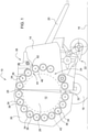
- FIG. 1 The drawing shows a baler 10 shown schematically, in the manner of an agricultural baler for pressing a round cylindrical bale 12, which has a first housing part 14, which is supported by means of wheels 16 on a substrate 18 and by means of a drawbar 20 to a towing vehicle, not shown, z. B. is a tractor connected.
- a receiving device 22 for receiving and feeding in crop material, which conveys cut crop material through a feed channel 24 into a baling chamber 26, with the first housing part 14 having a front part of the pressing chamber 26 surrounds.
- a bearing 28 for a pivotable second housing part 30 which surrounds a rear part of the pressing chamber 26 .
- the second housing part 30 releases an opening 32 through which a bale 12 pressed by the baling press 10 can be set down or unloaded or ejected.
- the pivotable second housing part 30 can be actuated (opened and closed) by means of servomotors (not shown) and thus represents an outlet flap for a bale 12 pressed in the baling chamber 26.
- the baling chamber 26 of the baling press 10 is designed so that its size cannot be changed, and the baling press 10 has a large number of pressing rollers 34 running parallel to one another (only a few pressing rollers 34 have been given the reference number 34 as an example), whose rolling axes 36 when the second housing part 24 is closed located in an arc of a circle, at least some of which are powered.
- the press rollers 34 also serve in particular to generate or maintain the rotation of the round bale 12 arranged in the baling chamber 20.
- the baler 10 is shown here as an example to show the opening 32 with the rear housing part 30 slightly open. However, this is closed during a pressing process.
- the baling press 10 comprises a wrapping device 38 which is equipped with a supply roll 40 for wrapping material 42 which feeds the wrapping material 42 to the baling chamber 26 through a feed gap 44 .
- a feed roller 46 is provided immediately below the feed gap 44 or adjacent to it, which, apart from its position, is the same as the other press rollers 34 and can be driven in rotation with them via a drive (not shown).
- the wrapping device 38 is also activated, a wrapping process that follows the baling process is initiated and the wrapping material 42 is fed from the supply roll 40 through the feed gap 44 into the baling chamber 26 and onto the bale 12 .
- the wrapping material 42 is wrapped around the bale 12 in such a way that it envelops a lateral surface 43 of the bale 12 .
- the bale 12 is deposited on the ground 18 via an unloading ramp (not shown) by opening the second housing part 30, which acts in the manner of an outlet flap, through the opening 32. Then the ride with the baler 10 is resumed and a new baling process begins.
- the encasing device 38 is basically designed in a known manner.
- the wrapping material 42 is fed to the feed gap 44 in such a way that it is gripped by the driven feed roller 46 and conveyed in the direction of the bale 12 .
- the wrapping material 42 is brought up to the feed roller 46 at least essentially from above, as a result of which it can be gripped and taken along by it in a simple manner (see FIG figure 2 ).
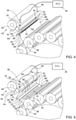
- FIG. 3 to 5 Figures now show the encasing apparatus 38 and encasing material 42 in successive phases of an encasing operation.
- the bale 12 is now almost entirely wrapped in wrapping material 42 and the wrapping operation is about to be completed.
- the wrapping material 42 is divided into sections 48 in the longitudinal direction such that one section 48 is used to wrap a bale 12, predetermined tear areas 50 being provided between the sections 48.
- these predetermined tear areas 50 are designed in the manner of perforation lines 52 extending across the width B of the wrapping material 42 .
- the wrapping material 42 has fold areas 54 and adhesive areas 56, the adhesive areas 56 each having two adhesive components 58, 60 designed in the manner of adhesive or adhesive strips.
- These adhesive components 58, 60 are in turn attached to the casing material 42 by means of further adhesive components 62, 64, which are only shown in outline.
- the fold areas 54 each have a first, a second and a third fold edge 66, 68, 70, which relative to the conveying direction F are provided lagging behind one another.
- the first fold edge 66 is provided in an end area 71 of a leading section 48
- the second fold edges 68, 70 are provided in a trailing section 48, with the adhesive area 56 and the predetermined tear area 50 being provided between the first fold edge 66 and the second fold edge 68 and the Adhesion area 56 the predetermined crack area 50 ahead.
- the first fold edge 66 and the second fold edge 68 also define a first side area 72 between them
- the second fold edge 68 and the third fold edge 70 define a second side area 74.
- the folding areas 52 are of this type folded together such that the predetermined tear area 54 and the adhesive area 56 are arranged between the side areas 72, 74, namely in such a way that the adhesive components 58, 60 come to rest on one another.
- the second adhesive component 60 is preferably in the form of a silicone-like material that only slightly adheres to the first adhesive component 58 in the folded state of the fold area 54 so that the fold area 54 when wound up on the supply roll 40 is separated from the first and second adhesive components 58, 60 is held together.
- the rotating bale 12 acts on the wrapping material 42 in such a way that it exerts a force acting on it in the conveying direction F, which force exceeds an adhesive force between the first and second adhesive components 58, 60 and unfolds the fold area 54.
- the first adhesive component 58 now comes into contact with the wrapping material 42 encasing the bale 12 and enters into a firmly adhering connection with it.
- the force applied by the rotating bale 12 now acts on the predetermined tear area 50 and separates the sections 48 along the perforation line 52 from one another.
- the bale 12 is now wrapped in wrapping material 42 and can be released from the baling chamber 26 .
- the casing material 42 also has a series of tangs 78 in the form of substantially round recesses 80 in a starting region 76 of each trailing section.
- the drivers 78 extend across the width B of the wrapping material 42 and are spaced apart and adjoin the predetermined tear area 50 that is leading in relation to the conveying direction F and are provided in front of the second folded edge 68 or between the leading predetermined tear area 50 and the second folded edge 68.
- the carriers 78 can grip the wrapping material 42 or an initial area 72 of each section, for example, by the bale 12 or by the material forming the bale 12, such as in the case of an agricultural bale, for example by stalks of crops such as straw or hay .
- the row of recesses 80 can also serve as a kind of safety device in the event that no separation occurs along the predetermined tear area 50 and/or the section 48 enveloping the bale 12 should be too short. Alternatively, a separation can now take place along the recesses 80 arranged in a row and thus a wrapping of the bale 12 with a second section 48 can be prevented.
- the wrapping device 38 has a supply device 82 (in figure 1 indicated) for the wrapping material 42, for example a feed lever provided pivotably on the wrapping device 38
- the feed lever can interact with the driver 78 or in particular engage in one of the recess(es) 80 in order to feed the wrapping material 42 the feed roller 46 and/or the bale 12.
- the interaction of such a feed device 82 with the driver 78 and in particular an engagement in one of the recess(es) 80 can also change the position of the wrapping material 42 and/or the section 48 of the wrapping material 42 gripped by the feed lever in relation to the feed device 82 and thus determine the wrapping device 38 or the bale 12. This can help ensure that the wrapping material 42 and/or in particular the section 48 for wrapping the bale 12 is positioned in such a way that the length of the section 48 following the feed device is at least essentially the same for each wrapping process.
- catches 78 can also be provided on conventional or known casing materials or on casing materials designed differently from the casing material described above, in particular on foils, or that a casing material 42 described above does not necessarily have to be provided with catches 78 of this type .
- a braking device 84 for a covering material 42 is shown.
- the braking device 84 described in more detail below can be used on a previously described wrapping device, but also on a conventional wrapping device or baling press and/or in conjunction with a previously described or conventional wrapping material, for example a net or film.
- the braking device 84 is effectively connected to a control or regulating device 86 of the baler 10 and has a sensor 88, of the type of an optical sensor 88, which can record whether there is an edge region 90 of the wrapping material 42 provided marking 92 is in a detection range of the sensor 88. If sensor 88 detects that there is a marking 92 in its detection range, it transmits this information to control or regulating device 86, which correspondingly activates braking device 84 in such a way that a braking means 94 of braking device 84 is applied to casing material 42 to slow it down.
- the marking 92 is arranged on the wrapping material 42 in such a way that it indicates to the braking device 84 to brake the wrapping material 42 when the starting region 72 of a section 48 which is lagging behind the section 48 enveloping a bale 10 or is after the section enveloping the bale 10 has been separated 48 now occupies a predetermined position at the free end along the predetermined tear area 50 (see figure 6 ).
- section 48 is decelerated in such a way that its starting area 72 or its free end is arranged in feed gap 44 in such a way that a distance A between starting area 72 and pressing chamber 26 is at least essentially the same at the beginning of each wrapping process.
- the wrapping material 42 or the starting area 72 is also held in contact with the feed roller 44 by a guide means 96 which is not necessary for the desired effect of the braking device.
- braking device 84 contributes to the fact that each bale 10 with an at least substantially equal amount of wrapping material 42 or, in the case of a previously described wrapping material 42 divided into sections 48 or a wrapping material 42 with predetermined tearing areas 50, has exactly one section 48 is wrapped or the respective section 48 is suitably positioned for wrapping a bale.
- the sections 48 can be separated along the predetermined tear area 50 without the aid of further aids, in particular without the use of a separating device or a knife arrangement.
- the braking device 84 shown can be used to increase a force acting on the predetermined tear area 50 or to apply an additional force at the end of a wrapping process.
Landscapes
- Life Sciences & Earth Sciences (AREA)
- Environmental Sciences (AREA)
- Storage Of Harvested Produce (AREA)
- Basic Packing Technique (AREA)
Description
Die vorliegende Erfindung betrifft eine landwirtschaftliche Ballenpresse nach dem Oberbegriff von Anspruch 1 und ein Verfahren zur Umhüllung eines Ballens mit einem Hüllmaterial Anspruch 5.The present invention relates to an agricultural baler according to the preamble of claim 1 and a method of wrapping a bale with a wrapping material of claim 5.
Bekannte Umhüllungseinrichtungen werden an Ballenpressen eingesetzt, um einen in einem Pressraum der Ballenpresse gebildeten Rundballen mit einem Hüllmaterial, beispielsweise einem Netz, einer Folie oder einem ähnlichen, gegebenenfalls auch semipermeablen, atmungsaktiven und/oder wasserabweisenden Material zu umhüllen, bevor dieser nach Abschluss der Umhüllung von der Ballenpresse abgegeben und danach auf dem Untergrund abgelegt oder an eine weitere Einrichtung, beispielsweise eine Wickeleinrichtung, übergeben wird.Known wrapping devices are used on baling presses in order to wrap a round bale formed in a baling chamber of the baling press with a wrapping material, for example a net, a film or a similar material, which may also be semi-permeable, breathable and/or water-repellent, before this, after the wrapping of delivered to the baler and then placed on the ground or transferred to another device, such as a winding device.
Derartige Ballenpressen werden sowohl im landwirtschaftlichen als auch im industriellen Bereich eingesetzt. Entsprechende landwirtschaftliche Pressen dienen beispielsweise zur Bildung von Erntegutballen, beispielsweise in der Art von Rundballen, und erzeugen häufig zumindest im Wesentlichen rundzylindrische Ballen aus Erntegut, beispielsweise in der Art von Stroh, Heu, Häckselgut etc.. Industrielle Pressen finden Verwendung bei der Verdichtung von Müll, Textilien oder anderen Stoffen bzw. bei deren Pressung zu Ballen.Such balers are used both in agriculture and in the industrial sector. Corresponding agricultural presses are used, for example, to form crop bales, for example of the round bale type, and often produce at least essentially round-cylindrical bales of crop, for example of the type of straw, hay, chopped material, etc. Industrial presses are used for compacting waste , textiles or other substances or when they are pressed into balls.
Die
Die der Erfindung zugrunde liegende Aufgabe wird darin gesehen, eine Ballenpresse und ein Verfahren anzugeben, durch welche die vorgenannten Nachteile überwunden werden.The object on which the invention is based is seen in specifying a baling press and a method through which the aforementioned disadvantages are overcome.
Die Aufgabe wird erfindungsgemäß durch die Lehre der Patentansprüche 1 und 5 gelöst. Weitere vorteilhafte Ausgestaltungen und Weiterbildungen der Erfindung gehen aus den Unteransprüchen hervor.The object is achieved according to the invention by the teaching of patent claims 1 and 5. Further advantageous configurations and developments of the invention emerge from the dependent claims.
Die Ballenpresse kann auch im industriellen Bereich, beispielsweise zur Bildung von Ballen aus Papier, Müll, Stoff oder anderen Materialien eingesetzt werden. Es ist darüber hinaus denkbar, dass es sich um eine Presse zur Herstellung von Quaderballen handelt, wie sie sowohl im landwirtschaftlichen als auch im industriellen Bereich Verwendung findet. Eine derartige Umhüllungseinrichtung kann mit jedem bekannten Hüllmaterial, beispielsweise einer Folie oder einem Netz eingesetzt werden. Besonders vorteilhaft ist ihr Einsatz aber dann, wenn ein Hüllmaterial verwendet wird, das bezogen auf seine Längserstreckung in vorzugsweise im Wesentlichen selbsttätig trennbare Abschnitte unterteilt ist, da hier eine genaue Positionierung des Hüllmaterials insbesondere zu Anfang eines Umhüllungsvorgangs dazu beiträgt, dass der Ballen mit einer bestimmten Menge an Hüllmaterial, insbesondere genau einem Abschnitt, umhüllt wird.The baling press can also be used in the industrial sector, for example to form bales of paper, waste, cloth or other materials. It is also conceivable that it is a press for the production of square bales, as used in both the agricultural and industrial sectors. Such a covering device can be used with any known covering material, for example a foil or a net. However, their use is particularly advantageous when a wrapping material is used which, based on its longitudinal extent, is divided into preferably essentially automatically separable sections, since precise positioning of the wrapping material, especially at the beginning of a wrapping process, helps to ensure that the bale has a certain Amount of encasing material, in particular exactly one section, is encased.
Ist ein Bremsmittel vorgesehen, so kann dieses direkt oder indirekt mit dem Hüllmaterial zusammenwirken.If a braking means is provided, it can interact directly or indirectly with the covering material.
Das Bremsmittel kann an das Hüllmaterial selektiv anlegbar vorgesehen sein, beispielsweise in dem es in der Art eines an das Hüllmittel anlegbaren bzw. von diesem abhebbaren Bremsklotz ausgebildet ist. Vorzugsweise ist aber in der Art einer Walze bzw. Rolle, insbesondere mit einer beschichteten, beispielsweise gummierten, und/oder profilierten Oberfläche ausgebildet. Das Bremsmittel kann aber auch in das Hüllmaterial eingreifen oder an diesem angreifen, um es abzubremsen. Hierzu ist es vorzugsweise in der Art einer Hebeleinrichtung ausgebildet, die entsprechend mit dem Hüllmaterial zusammenwirkt, beispielsweise in dem sie in eine, vorzugsweise in einem Randbereich vorgesehene Aussparung eingreift, um das Hüllmaterial abzubremsen und/oder dessen Position zu bestimmen.The braking means can be provided so that it can be placed selectively on the covering material, for example in that it is designed in the manner of a brake block that can be placed on the covering means or lifted from it. However, it is preferably designed in the form of a cylinder or roller, in particular with a coated, for example rubberized, and/or profiled surface. However, the braking means can also engage in the wrapping material or act on it in order to brake it. For this purpose, it is preferably designed in the form of a lever device which interacts with the casing material, for example by engaging in a recess preferably provided in an edge region, in order to decelerate the casing material and/or to determine its position.
Ist ein Antrieb zur Förderung des Hüllmaterials vorgesehen, so kann dieser eine Förderung des Hüllmaterials selektiv unterbinden und/oder unterbrechen. Ein derartiger Antrieb kann beispielsweise eine Vorratsrolle, auf der das Hüllmaterial aufgewickelt ist, in Rotation versetzen. Hierzu kann der Antrieb die Vorratsrolle direkt antreiben oder aber indirekt auf die Vorratsrolle wirken, in dem er beispielsweise von außen auf die Vorratsrolle bzw. das Hüllmaterial wirkt. So kann beispielsweise vorgesehen sein, dass der Antrieb beispielsweise eine/die Walze bzw. Rolle antreibt, die wiederum an der Vorratsrolle angreift, um diese in Rotation versetzen zu können. Eine derartige Rolle oder Walze kann aber auch vorgesehen sein, um Hüllmaterial von einer Vorratsrolle abzuziehen. Es ist aber auch denkbar, dass der Antrieb eine Zufuhrrolle antreibt, die beispielsweise zusammen mit insbesondere weiteren Pressmitteln den Pressraum der Ballenpresse bestimmt. Der Antrieb kann aber auch in der Art eines insbesondere elektrischen Schrittmotors ausgebildet sein. Es ist aber auch denkbar, dass das Bremsmittel in den Antrieb eingreift, an diesen angreift und/oder diesen abbremst, beispielsweise in dem es auf einen Riemen oder eine Antriebsscheibe eines Riementriebs einwirkt.If a drive is provided for conveying the wrapping material, it can selectively suppress and/or interrupt conveying of the wrapping material. Such a drive can, for example, rotate a supply roll on which the wrapping material is wound. For this purpose, the drive can drive the supply roll directly or act indirectly on the supply roll, for example by acting on the supply roll or the wrapping material from the outside. For example be provided that the drive drives, for example, a / the roller or roller, which in turn acts on the supply roll in order to set them in rotation. However, such a roll or cylinder can also be provided in order to pull off the wrapping material from a supply roll. However, it is also conceivable for the drive to drive a feed roller which, for example together with in particular other pressing means, determines the baling chamber of the baling press. However, the drive can also be designed in the form of an electric stepping motor in particular. However, it is also conceivable that the braking means engages in the drive, acts on it and/or brakes it, for example by acting on a belt or a drive pulley of a belt drive.
Ein Verfahren nach Anspruch 5 kann mit jedem bekannten Hüllmaterial, beispielsweise einer Folie oder einem Netz eingesetzt werden. Besonders vorteilhaft ist sein Einsatz aber dann, wenn ein Hüllmaterial verwendet wird, das bezogen auf seine Längserstreckung in vorzugsweise im Wesentlichen selbsttätig trennbare Abschnitte unterteilt ist, da hier eine genaue Positionierung des Hüllmaterials insbesondere zu Anfang eines Umhüllungsvorgangs dazu beiträgt, dass der Ballen mit einer bestimmten Menge an Hüllmaterial, insbesondere genau einem Abschnitt umhüllt werden kann.A method according to claim 5 can be used with any known covering material, for example a foil or a net. However, its use is particularly advantageous when a wrapping material is used that is divided into sections that can be separated, preferably essentially automatically, based on its longitudinal extent, since precise positioning of the wrapping material, especially at the beginning of a wrapping process, helps to ensure that the bale has a specific Amount of wrapping material, in particular exactly one section can be wrapped.
Anhand der Zeichnung, die ein Ausführungsbeispiel der Erfindung zeigt, werden nachfolgend die Erfindung sowie weitere Vorteile und vorteilhafte Weiterbildungen der Erfindung und Ausgestaltungen der Erfindung näher beschrieben und erläutert.The invention and further advantages and advantageous developments of the invention and refinements of the invention are described and explained in more detail below with reference to the drawing, which shows an exemplary embodiment of the invention.
Es zeigt:
- Fig. 1
- eine schematische Seitenansicht einer landwirtschaftlichen Ballenpresse mit Pressmitteln und einer Umhüllungseinrichtung,
- Fig. 2
- eine vergrößerte Darstellung der Umhüllungseinrichtung mit einem auf einer Vorratsrolle aufgewickelten Hüllmaterial während der Umhüllung eines Ballens mit Hüllmaterial,
- Fig. 3
- eine Darstellung gemäß
Figur 2 gegen Ende des Umhüllungsvorgangs, wobei der Ballen bereits vollständig mit Hüllmaterial umwickelt ist, - Fig. 4
- eine Darstellung gemäß den
Figuren 2 und 3 , wobei sich ein Faltbereich des Hüllmaterials beginnt, sich zu entfalten, - Fig. 5
- eine Darstellung gemäß
Figur 4 bei fast vollständig entfaltetem Faltbereich und - Fig. 6
- ein Darstellung eines in einem Zufuhrspalt angeordneten Anfangsbereich des Hüllmaterials.
- 1
- a schematic side view of an agricultural baler with pressing means and a wrapping device,
- 2
- an enlarged view of the wrapping device with a wrapping material wound up on a supply roll during the wrapping of a bale with wrapping material,
- 3
- a representation according to
figure 2 towards the end of the wrapping process, when the bale is already completely wrapped with wrapping material, - 4
- a representation according to
Figures 2 and 3 , where a fold area of the wrapping material begins to unfold, - figure 5
- a representation according to
figure 4 with the fold area almost completely unfolded and - 6
- a representation of a starting area of the casing material arranged in a feed gap.
In der
An einer bezogen auf eine Vorwärtsfahrtrichtung vorderen, unteren Seite des ersten Gehäuseteils 14 befindet sich in bekannter Weise eine Aufnahmevorrichtung 22 zur Aufnahme und Zufuhr von Erntegut, die geschnittenes Erntegut durch einen Zufuhrkanal 24 in einen Pressraum 26 fördert, wobei der erste Gehäuseteil 14 einen vorderen Teil des Pressraum 26 umgibt. An dem rückwärtigen oberen Eckbereich des ersten Gehäuseteils 14 befindet sich ein Lager 28 für einen schwenkbaren zweiten Gehäuseteil 30, der einen hinteren Teil des Pressraums 26 umgibt. Der zweite Gehäuseteil 30 gibt im geöffneten Zustand eine Öffnung 32 frei, durch welche ein von der Ballenpresse 10 gepresster Ballen 12 abgesetzt bzw. entladen oder ausgeworfen werden kann. Der schwenkbare zweite Gehäuseteil 30 kann mittels Stellmotoren (nicht gezeigt) betätigt werden (geöffnet und geschlossen werden) und stellt somit eine Auslassklappe für einen in dem Pressraum 26 gepressten Ballen 12 dar.On a front, lower side of the
Gemäß dem vorliegenden Ausführungsbeispiel ist der Pressraum 26 der Ballenpresse 10 größenunveränderlich ausgebildet und die Ballenpresse 10 weist eine Vielzahl zueinander parallel verlaufender Pressrollen 34 (exemplarisch wurden hier nur einige wenige Pressrollen 34 mit dem Bezugszeichen 34 versehen), deren Rollachsen 36 bei geschlossenem zweiten Gehäuseteil 24 auf einem Kreisbogen gelegen sind, und von denen wenigstens einige angetrieben sind. Die Pressrollen 34 dienen, neben einem Pressen und einer Formgebung, insbesondere auch einer Rotationserzeugung oder einer Rotationserhaltung des in dem Pressraum 20 angeordneten Rundballens 12. Die Ballenpresse 10 ist hier exemplarisch zur Darstellung der Öffnung 32 mit leicht geöffnetem hinterem Gehäuseteil 30 abgebildet. Während eines Pressvorgangs ist dieser jedoch geschlossen.According to the present exemplary embodiment, the
Ferner umfasst die Ballenpresse 10 eine Umhüllungseinrichtung 38, die mit einer Vorratsrolle 40 für Hüllmaterial 42 bestückt ist, die das Hüllmaterial 42 dem Pressraum 26 durch einen Zufuhrspalt 44 zuführt. Unmittelbar unterhalb des Zufuhrspalts 44 bzw. an diesen angrenzend ist eine Zufuhrrolle 46 vorgesehen, die abgesehen von ihrer Position, den übrigen Pressrollen 34 gleicht und mit diesen über einen nicht gezeigten Antrieb rotatorisch angetrieben werden kann.Furthermore, the baling
Nachdem der eigentliche Ballenpressvorgang, also die Erntegutaufnahme und Bildung eines Ballens 12 durch die Pressrollen 34 abgeschlossen ist, wird eine Fahrt über den Untergrund 18 unterbrochen, da die Ballenpresse 10 mit dem Ballen 12 gefüllt ist und kein weiteres Erntegut mehr in den Pressraum 26 aufgenommen werden soll bzw. kann. Zu dieser Zeit wird auch die Umhüllungseinrichtung 38 aktiviert, ein sich dem Ballenpressvorgang anschließender Umhüllungsvorgang eingeleitet und das Hüllmaterial 42 von der Vorratsrolle 40 durch den Zufuhrspalt 44 in den Pressraum 26 und an den Ballen 12 herangeführt. Durch eine anhaltende Drehung des sich in dem Pressraum 26 befindlichen Ballens 12 wird das Hüllmaterial 42 derart um den Ballen 12 gewickelt, dass es eine Mantelfläche 43 des Ballens 12 umhüllt. Nachdem der Umhüllungsvorgang abgeschlossen ist, wird der Ballen 12 mittels Öffnen des in der Art einer Auslassklappe wirkenden zweiten Gehäuseteils 30 durch die Öffnung 32 über eine Entladerampe (nicht gezeigt) auf dem Untergrund 18 abgelegt. Sodann wird die Fahrt mit der Ballenpresse 10 wieder aufgenommen und ein neuer Ballenpressvorgang beginnt.After the actual baling process, i.e. the harvested crop being picked up and a
Es wird nun auch auf die
Die
Darüber hinaus weist das Hüllmaterial 42 Faltbereiche 54 und Haftbereiche 56 auf, wobei die Haftbereiche 56 jeweils zwei in der Art von Haft- bzw. Klebestreifen ausgebildete Haftkomponenten 58, 60 aufweisen. Diese Haftkomponenten 58, 60 sind wiederum mittels weiterer, nur andeutungsweise gezeigter Haftkomponenten 62, 64 an dem Hüllmaterial 42 angebracht.In addition, the wrapping
Die Faltbereiche 54 weisen jeweils eine erste, eine zweite und eine dritte Faltkante 66, 68, 70 auf, welche bezogen auf die Förderrichtung F einander nacheilend vorgesehen sind. Die erste Faltkante 66 ist in einem Endbereich 71 eines voreilenden Abschnitts 48, die zweiten Faltkanten 68, 70 sind in einem nacheilenden Abschnitt 48 vorgesehen, wobei der Haftbereich 56 und der Sollrissbereich 50 zwischen der ersten Faltkante 66 und der zweiten Faltkante 68 vorgesehen sind und der Haftbereich 56 dem Sollrissbereich 50 voreilt. Die erste Faltkante 66 und die zweite Faltkante 68 bestimmen darüber hinaus zwischen sich einen ersten Seitenbereich 72 und die zweite Faltkante 68 und die dritte Faltkante 70 einen zweiten Seitenbereich 74.The
Ist das Hüllmaterial 42 auf der Vorratsrolle 40 aufgewickelt, so sind die Faltbereiche 52 derart zusammengefaltet, dass der Sollrissbereich 54 sowie der Haftbereich 56 zwischen den Seitenbereiche 72, 74 angeordnet sind, nämlich derart, dass die Haftkomponenten 58, 60 aufeinander zu liegen kommen. Vorzugsweise ist die zweite Haftkomponente 60 als ein silikonartiges Material ausbildet, das an der ersten Haftkomponente 58 in gefaltetem Zustand des Faltbereichs 54 nur derart leicht anhaftet, dass der Faltbereich 54 in einem auf der Vorratsrolle 40 aufgewickelten Zustand von der ersten und zweiten Haftkomponente 58, 60 zusammengehalten wird.If the wrapping
Ist der Ballen 12 vollständig mit Hüllmaterial 42 umwickelt, wie dies in den
Die von dem rotierenden Ballen 12 aufgebrachte Kraft wirkt nun auf den Sollrissbereich 50 und trennt die Abschnitte 48 entlang der Perforationslinie 52 voneinander. Der Ballen 12 ist nun mit Hüllmaterial 42 umhüllt und kann aus dem Pressraum 26 abgegeben werden.The force applied by the rotating
Das Hüllmaterial 42 weist darüber hinaus in einem Anfangsbereich 76 eines jeden nacheilenden Abschnitts eine Reihe von Mitnehmern 78 in der Art von im Wesentlichen runden Ausnehmungen 80 auf. Die Mitnehmer 78 erstrecken sich quer über die Breite B des Hüllmaterials 42 und grenzen beabstandet an den bezogen auf die Förderrichtung F voreilenden Sollrissbereich 50 an und sind vor der zweiten Faltkante 68 bzw. zwischen dem voreilenden Sollrissbereich 50 und der zweiten Faltkante 68 vorgesehen.The
Durch die Mitnehmer 78 kann das Hüllmaterial 42 bzw. ein Anfangsbereich 72 eines jeden Abschnitts beispielsweise durch den Ballen 12 bzw. durch den Ballen 12 bildendes Material, wie im Falle eines landwirtschaftlichen Ballens beispielsweise durch Halme von Erntegut in der Art von Stroh oder Heu ergriffen werden.The
Darüber hinaus kann die Reihe von Ausnehmungen 80 auch in der Art einer Sicherheitseinrichtung für den Fall dienen, dass keine Trennung entlang des Sollrissbereichs 50 erfolgt und/oder der den Ballen 12 umhüllende Abschnitt 48 zu kurz sein sollte. Alternativ kann nun eine Trennung entlang der in Reihe angeordneten Ausnehmungen 80 erfolgen und so einem Umwickeln des Ballens 12 mit einem zweiten Abschnitt 48 vorgebeugt werden.In addition, the row of
Weist die Umhüllungseinrichtung 38 eine Zufuhreinrichtung 82 (in
Es sei hier angemerkt, dass derartige Mitnehmer 78 auch an konventionellen bzw. bekannten oder an von dem zuvor beschriebenen Hüllmaterial abweichend ausgebildeten Hüllmaterialien, insbesondere an Folien, vorgesehen sein können, bzw. ein zuvor beschriebenes Hüllmaterial 42 nicht notwendigerweise mit derartigen Mitnehmern 78 versehen werden muss.It should be noted here that
Es wird nun insbesondere auf die
Gemäß dem vorliegenden Ausführungsbeispiel ist die Bremseinrichtung 84 wirksam mit einer Steuer- oder Regeleinrichtung 86 der Ballenpresse 10 verbunden und weist einen Sensor 88, in der Art eines optischen Sensors 88, auf, der aufnehmen kann, ob sich eine in einem Randbereich 90 des Hüllmaterials 42 vorgesehene Markierung 92 in einem Erfassungsbereich des Sensors 88 befindet. Erkennt der Sensor 88, dass eine Markierung 92 in seinem Erfassungsbereich vorhanden ist, überträgt er diese Information an die Steuer- oder Regeleinrichtung 86, die entsprechend die Bremseinrichtung 84 in der Art aktiviert, dass ein Bremsmittel 94 der Bremseinrichtung 84 an das Hüllmaterial 42 angelegt wird, um dieses abzubremsen. Die Markierung 92 ist auf dem Hüllmaterial 42 derart angeordnet, dass sie der Bremseinrichtung 84 anzeigt, das Hüllmaterial 42 abzubremsen, wenn der Anfangsbereich 72 eines dem einen Ballen 10 umhüllenden Abschnitt 48 nacheilenden Abschnitts 48 bzw. sein nach einem Abtrennen des den Ballen 10 umhüllenden Abschnitts 48 entlang des Sollrissbereichs 50 nun freies Ende eine vorbestimmte Position einnimmt (siehe
Insbesondere wird der Abschnitt 48 derart abgebremst, dass sein Anfangsbereich 72 bzw. sein freies Ende derart in dem Zufuhrspalt 44 angeordnet ist, dass ein Abstand A zwischen dem Anfangsbereich 72 und dem Pressraum 26 zu Beginn eines jeden Umhüllungsvorgangs zumindest im Wesentlichen gleich ist. Gemäß der Darstellung in
Auf diese Weise trägt die Bremseinrichtung 84 dazu bei, dass jeder Ballen 10 mit einer zumindest im Wesentlichen gleichen Menge an Hüllmaterial 42 bzw. bei einem zuvor beschriebenen, in Abschnitte 48 unterteilten Hüllmaterial 42 bzw. einem Hüllmaterial 42 mit Sollrissbereichen 50 mit genau einem Abschnitt 48 umhüllt wird bzw. der jeweilige Abschnitt 48 zur Umhüllung eines Ballens passend positioniert wird.In this way,
Das Trennen der Abschnitte 48 entlang des Sollrissbereichs 50 kann ohne Zuhilfenahme weiterer Hilfsmittel, insbesondere ohne den Einsatz einer Trenneinrichtung bzw. einer Messeranordnung erfolgen. Darüber hinaus oder auch alternativ kann durch die gezeigte Bremseinrichtung 84 zum Abschluss eines Umhüllungsvorgangs aber eine auf den Sollrissbereich 50 wirkende Kraft erhöht bzw. eine zusätzliche Kraft aufgebracht werden.The
Claims (5)
- Agricultural baler (10) for forming round-cylindrical bales (12) in a pressing chamber (26) of the baler (10), having a wrapping device (38) for wrapping a bale (12), comprising wrapping material (42), wherein the wrapping device (38) comprises a braking device (84) for the wrapping material (42) and the braking device (84) is configured such that it causes the wrapping material (84), in particular at the start of a wrapping operation, to take up an at least substantially predetermined position, wherein the braking device (84) is operatively connected to an open-loop or closed-loop control device (86) of the baler (10) and has a sensor (88), characterized in that the sensor (88) is an optical sensor with which it is possible to register whether a marking (92) provided in a peripheral region (90) of the wrapping material (42) is located in a sensing region of the sensor (88), wherein the marking (92) is arranged on the wrapping material (42) such that the marking (92) indicates to the braking device (84) that it needs to brake the wrapping material (42) when a starting region (72) of a portion (48) trailing the portion (48) wrapping a bale (10), or its end that is now free after the portion (48) wrapping the bale (10) has been severed along the predetermined tearing region (50), takes up the predetermined position, and the portion (48) is able to be braked such that its starting region (72), or its free end, is arranged in the feed gap (44) such that a spacing (A) between the starting region (72) and the pressing chamber (26) is at least substantially identical at the start of each wrapping operation.
- Baler according to Claim 1, characterized in that at least one braking means (94) is provided, which can interact directly or indirectly with the wrapping material (42).
- Baler according to Claim 2, characterized in that the braking means (94) is intended to be placeable selectively against the wrapping material (42) and/or can selectively engage in or act on the wrapping material (42), and is configured preferably in the manner of a roller or roll or of a lever device.
- Baler according to one of the preceding claims, characterized in that a drive for delivering the wrapping material (42) is provided, said drive being able to selectively prevent delivery of the wrapping material (42) and/or to interact with the braking means (94).
- Method for wrapping a bale (12) with a wrapping material (42) by means of an agricultural baler (10) according to one of the preceding claims, and for forming round-cylindrical bales (12) in a pressing chamber (26) of the baler (10), wherein a braking device (84) of the wrapping device (38) acts on the wrapping material (42) or interacts therewith such that the wrapping material (42), at the start of a wrapping operation, takes up an at least substantially predetermined position, wherein the braking device (84) is operatively connected to an open-loop or closed-loop control device (86) of the baler (10) and has an optical sensor (88), wherein the optical sensor is used to register whether a marking (92) provided in a peripheral region (90) of the wrapping material (42) is in a sensing region of the sensor (88), and wherein the marking (92) is arranged on the wrapping material (42) such that the marking (92) indicates to the braking device (84) that it needs to brake the wrapping material (42) when a starting region (72) of a portion (48) trailing the portion (48) wrapping a bale (10), or its end that is now free after the portion (48) wrapping the bale (10) has been severed along the predetermined tearing region (50), takes up the predetermined position, and the portion (48) is able to be braked such that its starting region (72), or its free end, is arranged in the feed gap (44) such that a spacing (A) between the starting region (72) and the pressing chamber (26) is at least substantially identical at the start of each wrapping operation.
Applications Claiming Priority (1)
| Application Number | Priority Date | Filing Date | Title |
|---|---|---|---|
| DE102017210849.5A DE102017210849A1 (en) | 2017-06-27 | 2017-06-27 | A wrapping device for wrapping a bale with a wrapping material, baling press and method |
Publications (2)
| Publication Number | Publication Date |
|---|---|
| EP3420806A1 EP3420806A1 (en) | 2019-01-02 |
| EP3420806B1 true EP3420806B1 (en) | 2022-02-23 |
Family
ID=62110976
Family Applications (1)
| Application Number | Title | Priority Date | Filing Date |
|---|---|---|---|
| EP18170536.9A Active EP3420806B1 (en) | 2017-06-27 | 2018-05-03 | Wrapping device for wrapping a bale with a wrapping material, a bale press and method |
Country Status (4)
| Country | Link |
|---|---|
| US (1) | US10939619B2 (en) |
| EP (1) | EP3420806B1 (en) |
| CN (1) | CN109121745B (en) |
| DE (1) | DE102017210849A1 (en) |
Family Cites Families (31)
| Publication number | Priority date | Publication date | Assignee | Title |
|---|---|---|---|---|
| GB8605301D0 (en) * | 1986-03-04 | 1986-04-09 | Frogbrook K H L | Baling machines & products |
| GB2204563A (en) * | 1987-04-29 | 1988-11-16 | Bridon Plc | Means and method of baling straw, hay and like materials |
| NL8701973A (en) * | 1987-08-21 | 1989-03-16 | Zweegers & Zonen P J | BALER. |
| US5282346A (en) * | 1992-05-14 | 1994-02-01 | Oji Seitai Kaisha, Ltd. | Unwrapping apparatus with swing arms and grippers |
| IT1296275B1 (en) * | 1997-08-01 | 1999-06-21 | Robopac Sa | FILM CUTTING METHOD AND DEVICE USED FOR WRAPPING GROUPS OF PRODUCTS. |
| US6269610B1 (en) * | 1998-08-20 | 2001-08-07 | Lantech Management Corp. | Method and apparatus for stretch wrapping a load |
| US6185900B1 (en) * | 1999-04-15 | 2001-02-13 | Lantech Management Corp. | Method and apparatus for stretch wrapping a load |
| DE10026066A1 (en) | 2000-05-25 | 2001-11-29 | Deere & Co | Device for wrapping a round bale |
| ITBO20020755A1 (en) * | 2002-12-02 | 2004-06-03 | Pieri Srl | APPARATUS FOR FASTENING WITHOUT WELDING OF THE TAIL |
| US6984431B2 (en) * | 2002-12-23 | 2006-01-10 | Tama Plastic Industry | Method and material for multi-material wrapping of items and a method of making the same |
| US7954633B2 (en) * | 2003-05-08 | 2011-06-07 | Deere & Company | Large round bale wrapped in protective wrapping and method for producing such a wrapped bale |
| DE102004023701A1 (en) * | 2004-05-11 | 2005-12-15 | Maschinenfabrik Bernard Krone Gmbh | Baler for agricultural harvested crops e.g. hay, straw, has conveying rollers, provided to packing apparatus, which directs packing material from packaging apparatus towards inlet of baling chamber |
| DE102006015854A1 (en) * | 2006-04-03 | 2007-10-04 | Claas Selbstfahrende Erntemaschinen Gmbh | Bandage material for covering of goods formed or pressed to goods bale, has an integrated electronic storage medium, which has memory chip, memory chip is formed by chip for radio frequency identification |
| ITBO20070183A1 (en) * | 2007-03-16 | 2008-09-17 | Atlanta Stretch S P A | PROCEDURE AND APPARATUS FOR THE AUTOMATIC FIXING OF THE TAIL OF AN EXTENSIBLE FILM WINDING MADE BY MACHINES WITH USUAL PALLETIZED LOADS. |
| US7694491B2 (en) * | 2007-10-30 | 2010-04-13 | Deere & Company | Cotton harvester for producing modules which can be automatically identified and oriented |
| US7908831B1 (en) * | 2007-11-27 | 2011-03-22 | Dugan Michael E | Stretch wrap rope converter and wrapping system |
| US7908822B2 (en) * | 2008-05-15 | 2011-03-22 | Cnh America Llc | Computer controlled automatic wrapping material dispensing system for a round baler |
| US7946095B2 (en) * | 2009-02-03 | 2011-05-24 | Agco Corporation | Meshwrap dispensing mechanism for round balers |
| EP2229811B1 (en) * | 2009-03-18 | 2014-07-02 | Deere & Company | Web wrap apparatus |
| BE1018706A3 (en) * | 2009-03-30 | 2011-07-05 | Cnh Belgium Nv | A METHOD FOR DRIVING A BRAKING DEVICE AND A ROUND BALL PRESS WITH A BRAKING DEVICE. |
| GB2475849A (en) * | 2009-12-01 | 2011-06-08 | Kuhn Geldrop Bv | Binding apparatus and method for binding a bale |
| US8141480B2 (en) * | 2010-08-23 | 2012-03-27 | Cnh America Llc | Automatic bale size calibration on round balers |
| EP2430905B1 (en) * | 2010-09-16 | 2013-03-27 | Deere & Company | Web wrap apparatus |
| US8516779B2 (en) * | 2011-03-16 | 2013-08-27 | Duratech Industries International, Inc. | Net wrap applicator for large round bales |
| DE102011079940A1 (en) * | 2011-07-27 | 2013-01-31 | Deere & Company | Round baler |
| US20140263590A1 (en) * | 2013-03-14 | 2014-09-18 | Mcnair Law Firm | Wrapping Material and Method Of Manufacturing The Same |
| US9949439B2 (en) * | 2013-05-31 | 2018-04-24 | Tama Plastic Industry | Hinged covering for adhesive surface |
| AU2014308544B2 (en) * | 2013-08-20 | 2017-02-23 | Tama group | A wrapping material and method of manufacture for baled harvested agricultural materials |
| US10377545B2 (en) * | 2015-03-24 | 2019-08-13 | L.P. Brown Company, Inc. | Wrapping materials for solid objects |
| CN106688456A (en) * | 2015-11-15 | 2017-05-24 | 重庆松瑞汽车销售有限公司 | Automatic net twining device of round bale bundling machine |
| CN105815051B (en) * | 2016-04-15 | 2017-12-19 | 安徽艾格瑞智能装备有限公司 | A kind of circular baler net chute installation |
-
2017
- 2017-06-27 DE DE102017210849.5A patent/DE102017210849A1/en not_active Withdrawn
-
2018
- 2018-05-03 EP EP18170536.9A patent/EP3420806B1/en active Active
- 2018-05-24 CN CN201810507508.9A patent/CN109121745B/en active Active
- 2018-06-19 US US16/011,724 patent/US10939619B2/en active Active
Also Published As
| Publication number | Publication date |
|---|---|
| EP3420806A1 (en) | 2019-01-02 |
| DE102017210849A1 (en) | 2018-12-27 |
| CN109121745A (en) | 2019-01-04 |
| US20180368329A1 (en) | 2018-12-27 |
| US10939619B2 (en) | 2021-03-09 |
| CN109121745B (en) | 2022-08-26 |
Similar Documents
| Publication | Publication Date | Title |
|---|---|---|
| EP1461995B1 (en) | Device for wrapping a bale with an envelope, bailing press and sensor | |
| EP1157603B1 (en) | Device for wrapping a round bale | |
| EP1813145B1 (en) | Device for wrapping a bale and baler | |
| DE69522303T2 (en) | Method and device for preparing and opening a web roll | |
| EP3421386A1 (en) | Casing material for a baling press and method | |
| EP1917849B1 (en) | Sheathing device | |
| EP2939523A1 (en) | Bale wrapping device and round baler that is provided with same | |
| DE102006009863A1 (en) | baler | |
| EP3421387B1 (en) | Shell material for a baling press | |
| DE10350622A1 (en) | baler | |
| EP0535532A2 (en) | Method of tying bales of crop and device therefor | |
| EP3721700B1 (en) | Round baler and bale wrapping device for a round baler | |
| EP1000860A1 (en) | Method and device for tying or enveloping objects | |
| EP3420806B1 (en) | Wrapping device for wrapping a bale with a wrapping material, a bale press and method | |
| EP3414991B1 (en) | Wrapping device and round baler | |
| EP1454521B1 (en) | Wrapping device for bales and baling press | |
| EP3590325A1 (en) | Round baler and detection method | |
| EP3501261B1 (en) | Guidance means, baler and method | |
| DE10309658B4 (en) | Device for wrapping a bale with a wrapping web, baling press and method | |
| EP3721699A1 (en) | Bale wrapping device for a baler, loading aid and baler | |
| DE102014116615A1 (en) | Substrate feeding device for a packaging tube manufacturing process and substrate feeding method | |
| EP3729952A1 (en) | Bale wrapping device for a round-bale press, round-bale press and method for operating the same | |
| EP3420805B1 (en) | Wrapping device, blocking device, baler and method for adapting a baler to a wrapping material |
Legal Events
| Date | Code | Title | Description |
|---|---|---|---|
| PUAI | Public reference made under article 153(3) epc to a published international application that has entered the european phase |
Free format text: ORIGINAL CODE: 0009012 |
|
| STAA | Information on the status of an ep patent application or granted ep patent |
Free format text: STATUS: THE APPLICATION HAS BEEN PUBLISHED |
|
| AK | Designated contracting states |
Kind code of ref document: A1 Designated state(s): AL AT BE BG CH CY CZ DE DK EE ES FI FR GB GR HR HU IE IS IT LI LT LU LV MC MK MT NL NO PL PT RO RS SE SI SK SM TR |
|
| AX | Request for extension of the european patent |
Extension state: BA ME |
|
| STAA | Information on the status of an ep patent application or granted ep patent |
Free format text: STATUS: REQUEST FOR EXAMINATION WAS MADE |
|
| 17P | Request for examination filed |
Effective date: 20190702 |
|
| RBV | Designated contracting states (corrected) |
Designated state(s): AL AT BE BG CH CY CZ DE DK EE ES FI FR GB GR HR HU IE IS IT LI LT LU LV MC MK MT NL NO PL PT RO RS SE SI SK SM TR |
|
| GRAP | Despatch of communication of intention to grant a patent |
Free format text: ORIGINAL CODE: EPIDOSNIGR1 |
|
| STAA | Information on the status of an ep patent application or granted ep patent |
Free format text: STATUS: GRANT OF PATENT IS INTENDED |
|
| INTG | Intention to grant announced |
Effective date: 20210929 |
|
| GRAS | Grant fee paid |
Free format text: ORIGINAL CODE: EPIDOSNIGR3 |
|
| GRAA | (expected) grant |
Free format text: ORIGINAL CODE: 0009210 |
|
| STAA | Information on the status of an ep patent application or granted ep patent |
Free format text: STATUS: THE PATENT HAS BEEN GRANTED |
|
| AK | Designated contracting states |
Kind code of ref document: B1 Designated state(s): AL AT BE BG CH CY CZ DE DK EE ES FI FR GB GR HR HU IE IS IT LI LT LU LV MC MK MT NL NO PL PT RO RS SE SI SK SM TR |
|
| REG | Reference to a national code |
Ref country code: GB Ref legal event code: FG4D Free format text: NOT ENGLISH |
|
| REG | Reference to a national code |
Ref country code: CH Ref legal event code: EP |
|
| REG | Reference to a national code |
Ref country code: DE Ref legal event code: R096 Ref document number: 502018008822 Country of ref document: DE |
|
| REG | Reference to a national code |
Ref country code: AT Ref legal event code: REF Ref document number: 1469742 Country of ref document: AT Kind code of ref document: T Effective date: 20220315 |
|
| REG | Reference to a national code |
Ref country code: IE Ref legal event code: FG4D Free format text: LANGUAGE OF EP DOCUMENT: GERMAN |
|
| REG | Reference to a national code |
Ref country code: LT Ref legal event code: MG9D |
|
| REG | Reference to a national code |
Ref country code: NL Ref legal event code: MP Effective date: 20220223 |
|
| PG25 | Lapsed in a contracting state [announced via postgrant information from national office to epo] |
Ref country code: SE Free format text: LAPSE BECAUSE OF FAILURE TO SUBMIT A TRANSLATION OF THE DESCRIPTION OR TO PAY THE FEE WITHIN THE PRESCRIBED TIME-LIMIT Effective date: 20220223 Ref country code: RS Free format text: LAPSE BECAUSE OF FAILURE TO SUBMIT A TRANSLATION OF THE DESCRIPTION OR TO PAY THE FEE WITHIN THE PRESCRIBED TIME-LIMIT Effective date: 20220223 Ref country code: PT Free format text: LAPSE BECAUSE OF FAILURE TO SUBMIT A TRANSLATION OF THE DESCRIPTION OR TO PAY THE FEE WITHIN THE PRESCRIBED TIME-LIMIT Effective date: 20220623 Ref country code: NO Free format text: LAPSE BECAUSE OF FAILURE TO SUBMIT A TRANSLATION OF THE DESCRIPTION OR TO PAY THE FEE WITHIN THE PRESCRIBED TIME-LIMIT Effective date: 20220523 Ref country code: NL Free format text: LAPSE BECAUSE OF FAILURE TO SUBMIT A TRANSLATION OF THE DESCRIPTION OR TO PAY THE FEE WITHIN THE PRESCRIBED TIME-LIMIT Effective date: 20220223 Ref country code: LT Free format text: LAPSE BECAUSE OF FAILURE TO SUBMIT A TRANSLATION OF THE DESCRIPTION OR TO PAY THE FEE WITHIN THE PRESCRIBED TIME-LIMIT Effective date: 20220223 Ref country code: HR Free format text: LAPSE BECAUSE OF FAILURE TO SUBMIT A TRANSLATION OF THE DESCRIPTION OR TO PAY THE FEE WITHIN THE PRESCRIBED TIME-LIMIT Effective date: 20220223 Ref country code: ES Free format text: LAPSE BECAUSE OF FAILURE TO SUBMIT A TRANSLATION OF THE DESCRIPTION OR TO PAY THE FEE WITHIN THE PRESCRIBED TIME-LIMIT Effective date: 20220223 Ref country code: BG Free format text: LAPSE BECAUSE OF FAILURE TO SUBMIT A TRANSLATION OF THE DESCRIPTION OR TO PAY THE FEE WITHIN THE PRESCRIBED TIME-LIMIT Effective date: 20220523 |
|
| PG25 | Lapsed in a contracting state [announced via postgrant information from national office to epo] |
Ref country code: PL Free format text: LAPSE BECAUSE OF FAILURE TO SUBMIT A TRANSLATION OF THE DESCRIPTION OR TO PAY THE FEE WITHIN THE PRESCRIBED TIME-LIMIT Effective date: 20220223 Ref country code: LV Free format text: LAPSE BECAUSE OF FAILURE TO SUBMIT A TRANSLATION OF THE DESCRIPTION OR TO PAY THE FEE WITHIN THE PRESCRIBED TIME-LIMIT Effective date: 20220223 Ref country code: GR Free format text: LAPSE BECAUSE OF FAILURE TO SUBMIT A TRANSLATION OF THE DESCRIPTION OR TO PAY THE FEE WITHIN THE PRESCRIBED TIME-LIMIT Effective date: 20220524 Ref country code: FI Free format text: LAPSE BECAUSE OF FAILURE TO SUBMIT A TRANSLATION OF THE DESCRIPTION OR TO PAY THE FEE WITHIN THE PRESCRIBED TIME-LIMIT Effective date: 20220223 |
|
| PG25 | Lapsed in a contracting state [announced via postgrant information from national office to epo] |
Ref country code: IS Free format text: LAPSE BECAUSE OF FAILURE TO SUBMIT A TRANSLATION OF THE DESCRIPTION OR TO PAY THE FEE WITHIN THE PRESCRIBED TIME-LIMIT Effective date: 20220623 |
|
| PG25 | Lapsed in a contracting state [announced via postgrant information from national office to epo] |
Ref country code: SM Free format text: LAPSE BECAUSE OF FAILURE TO SUBMIT A TRANSLATION OF THE DESCRIPTION OR TO PAY THE FEE WITHIN THE PRESCRIBED TIME-LIMIT Effective date: 20220223 Ref country code: SK Free format text: LAPSE BECAUSE OF FAILURE TO SUBMIT A TRANSLATION OF THE DESCRIPTION OR TO PAY THE FEE WITHIN THE PRESCRIBED TIME-LIMIT Effective date: 20220223 Ref country code: RO Free format text: LAPSE BECAUSE OF FAILURE TO SUBMIT A TRANSLATION OF THE DESCRIPTION OR TO PAY THE FEE WITHIN THE PRESCRIBED TIME-LIMIT Effective date: 20220223 Ref country code: EE Free format text: LAPSE BECAUSE OF FAILURE TO SUBMIT A TRANSLATION OF THE DESCRIPTION OR TO PAY THE FEE WITHIN THE PRESCRIBED TIME-LIMIT Effective date: 20220223 Ref country code: DK Free format text: LAPSE BECAUSE OF FAILURE TO SUBMIT A TRANSLATION OF THE DESCRIPTION OR TO PAY THE FEE WITHIN THE PRESCRIBED TIME-LIMIT Effective date: 20220223 Ref country code: CZ Free format text: LAPSE BECAUSE OF FAILURE TO SUBMIT A TRANSLATION OF THE DESCRIPTION OR TO PAY THE FEE WITHIN THE PRESCRIBED TIME-LIMIT Effective date: 20220223 |
|
| REG | Reference to a national code |
Ref country code: DE Ref legal event code: R097 Ref document number: 502018008822 Country of ref document: DE |
|
| PG25 | Lapsed in a contracting state [announced via postgrant information from national office to epo] |
Ref country code: AL Free format text: LAPSE BECAUSE OF FAILURE TO SUBMIT A TRANSLATION OF THE DESCRIPTION OR TO PAY THE FEE WITHIN THE PRESCRIBED TIME-LIMIT Effective date: 20220223 |
|
| PLBE | No opposition filed within time limit |
Free format text: ORIGINAL CODE: 0009261 |
|
| REG | Reference to a national code |
Ref country code: CH Ref legal event code: PL |
|
| STAA | Information on the status of an ep patent application or granted ep patent |
Free format text: STATUS: NO OPPOSITION FILED WITHIN TIME LIMIT |
|
| REG | Reference to a national code |
Ref country code: BE Ref legal event code: MM Effective date: 20220531 |
|
| GBPC | Gb: european patent ceased through non-payment of renewal fee |
Effective date: 20220523 |
|
| PG25 | Lapsed in a contracting state [announced via postgrant information from national office to epo] |
Ref country code: MC Free format text: LAPSE BECAUSE OF FAILURE TO SUBMIT A TRANSLATION OF THE DESCRIPTION OR TO PAY THE FEE WITHIN THE PRESCRIBED TIME-LIMIT Effective date: 20220223 Ref country code: LU Free format text: LAPSE BECAUSE OF NON-PAYMENT OF DUE FEES Effective date: 20220503 Ref country code: LI Free format text: LAPSE BECAUSE OF NON-PAYMENT OF DUE FEES Effective date: 20220531 Ref country code: CH Free format text: LAPSE BECAUSE OF NON-PAYMENT OF DUE FEES Effective date: 20220531 |
|
| 26N | No opposition filed |
Effective date: 20221124 |
|
| PG25 | Lapsed in a contracting state [announced via postgrant information from national office to epo] |
Ref country code: SI Free format text: LAPSE BECAUSE OF FAILURE TO SUBMIT A TRANSLATION OF THE DESCRIPTION OR TO PAY THE FEE WITHIN THE PRESCRIBED TIME-LIMIT Effective date: 20220223 |
|
| PG25 | Lapsed in a contracting state [announced via postgrant information from national office to epo] |
Ref country code: IE Free format text: LAPSE BECAUSE OF NON-PAYMENT OF DUE FEES Effective date: 20220503 |
|
| PG25 | Lapsed in a contracting state [announced via postgrant information from national office to epo] |
Ref country code: GB Free format text: LAPSE BECAUSE OF NON-PAYMENT OF DUE FEES Effective date: 20220523 Ref country code: BE Free format text: LAPSE BECAUSE OF NON-PAYMENT OF DUE FEES Effective date: 20220531 |
|
| PG25 | Lapsed in a contracting state [announced via postgrant information from national office to epo] |
Ref country code: IT Free format text: LAPSE BECAUSE OF FAILURE TO SUBMIT A TRANSLATION OF THE DESCRIPTION OR TO PAY THE FEE WITHIN THE PRESCRIBED TIME-LIMIT Effective date: 20220223 |
|
| PG25 | Lapsed in a contracting state [announced via postgrant information from national office to epo] |
Ref country code: HU Free format text: LAPSE BECAUSE OF FAILURE TO SUBMIT A TRANSLATION OF THE DESCRIPTION OR TO PAY THE FEE WITHIN THE PRESCRIBED TIME-LIMIT; INVALID AB INITIO Effective date: 20180503 |
|
| PG25 | Lapsed in a contracting state [announced via postgrant information from national office to epo] |
Ref country code: MK Free format text: LAPSE BECAUSE OF FAILURE TO SUBMIT A TRANSLATION OF THE DESCRIPTION OR TO PAY THE FEE WITHIN THE PRESCRIBED TIME-LIMIT Effective date: 20220223 Ref country code: CY Free format text: LAPSE BECAUSE OF FAILURE TO SUBMIT A TRANSLATION OF THE DESCRIPTION OR TO PAY THE FEE WITHIN THE PRESCRIBED TIME-LIMIT Effective date: 20220223 |
|
| PG25 | Lapsed in a contracting state [announced via postgrant information from national office to epo] |
Ref country code: TR Free format text: LAPSE BECAUSE OF FAILURE TO SUBMIT A TRANSLATION OF THE DESCRIPTION OR TO PAY THE FEE WITHIN THE PRESCRIBED TIME-LIMIT Effective date: 20220223 |
|
| PGFP | Annual fee paid to national office [announced via postgrant information from national office to epo] |
Ref country code: DE Payment date: 20240419 Year of fee payment: 7 |
|
| REG | Reference to a national code |
Ref country code: AT Ref legal event code: MM01 Ref document number: 1469742 Country of ref document: AT Kind code of ref document: T Effective date: 20230503 |
|
| PG25 | Lapsed in a contracting state [announced via postgrant information from national office to epo] |
Ref country code: AT Free format text: LAPSE BECAUSE OF NON-PAYMENT OF DUE FEES Effective date: 20230503 |
|
| PG25 | Lapsed in a contracting state [announced via postgrant information from national office to epo] |
Ref country code: AT Free format text: LAPSE BECAUSE OF NON-PAYMENT OF DUE FEES Effective date: 20230503 |
|
| PGFP | Annual fee paid to national office [announced via postgrant information from national office to epo] |
Ref country code: FR Payment date: 20240527 Year of fee payment: 7 |