EP3420324B1 - A method and system for monitoring parameters of a moving object - Google Patents
A method and system for monitoring parameters of a moving object Download PDFInfo
- Publication number
- EP3420324B1 EP3420324B1 EP17755938.2A EP17755938A EP3420324B1 EP 3420324 B1 EP3420324 B1 EP 3420324B1 EP 17755938 A EP17755938 A EP 17755938A EP 3420324 B1 EP3420324 B1 EP 3420324B1
- Authority
- EP
- European Patent Office
- Prior art keywords
- imaging
- movement
- frequency
- moving object
- plane
- Prior art date
- Legal status (The legal status is an assumption and is not a legal conclusion. Google has not performed a legal analysis and makes no representation as to the accuracy of the status listed.)
- Active
Links
- 238000000034 method Methods 0.000 title claims description 40
- 238000012544 monitoring process Methods 0.000 title claims description 11
- 238000003384 imaging method Methods 0.000 claims description 101
- 230000033001 locomotion Effects 0.000 claims description 99
- 230000001427 coherent effect Effects 0.000 claims description 42
- 238000005286 illumination Methods 0.000 claims description 36
- 230000002123 temporal effect Effects 0.000 claims description 27
- 230000003287 optical effect Effects 0.000 claims description 26
- 238000001514 detection method Methods 0.000 claims description 17
- 230000009466 transformation Effects 0.000 claims description 13
- 230000010363 phase shift Effects 0.000 claims description 10
- 230000000638 stimulation Effects 0.000 claims description 9
- 230000001902 propagating effect Effects 0.000 claims description 8
- 238000006073 displacement reaction Methods 0.000 claims description 6
- 238000013519 translation Methods 0.000 claims description 6
- 230000003993 interaction Effects 0.000 claims description 5
- 230000004044 response Effects 0.000 claims description 5
- 230000000737 periodic effect Effects 0.000 claims description 3
- 230000001939 inductive effect Effects 0.000 claims description 2
- 238000012545 processing Methods 0.000 description 14
- 238000004458 analytical method Methods 0.000 description 6
- 238000005070 sampling Methods 0.000 description 6
- 230000008859 change Effects 0.000 description 5
- 238000002474 experimental method Methods 0.000 description 5
- 230000006870 function Effects 0.000 description 5
- 230000010349 pulsation Effects 0.000 description 5
- 210000001519 tissue Anatomy 0.000 description 5
- 238000005259 measurement Methods 0.000 description 4
- 239000000203 mixture Substances 0.000 description 4
- 230000003595 spectral effect Effects 0.000 description 4
- 238000000926 separation method Methods 0.000 description 3
- 238000012360 testing method Methods 0.000 description 3
- 238000013459 approach Methods 0.000 description 2
- 230000001066 destructive effect Effects 0.000 description 2
- 230000010076 replication Effects 0.000 description 2
- 238000000844 transformation Methods 0.000 description 2
- 241000699666 Mus <mouse, genus> Species 0.000 description 1
- 241000699670 Mus sp. Species 0.000 description 1
- 230000009471 action Effects 0.000 description 1
- 238000006243 chemical reaction Methods 0.000 description 1
- 238000004891 communication Methods 0.000 description 1
- 230000000295 complement effect Effects 0.000 description 1
- 238000004590 computer program Methods 0.000 description 1
- 230000009977 dual effect Effects 0.000 description 1
- 238000005516 engineering process Methods 0.000 description 1
- 239000000835 fiber Substances 0.000 description 1
- 238000005305 interferometry Methods 0.000 description 1
- 239000003550 marker Substances 0.000 description 1
- 230000007935 neutral effect Effects 0.000 description 1
- 239000013307 optical fiber Substances 0.000 description 1
- 238000003909 pattern recognition Methods 0.000 description 1
- 230000035515 penetration Effects 0.000 description 1
- 230000008569 process Effects 0.000 description 1
- 230000005855 radiation Effects 0.000 description 1
- 230000035945 sensitivity Effects 0.000 description 1
- 210000004872 soft tissue Anatomy 0.000 description 1
- 230000006641 stabilisation Effects 0.000 description 1
- 238000011105 stabilization Methods 0.000 description 1
- 230000003746 surface roughness Effects 0.000 description 1
- 239000013598 vector Substances 0.000 description 1
- 238000000827 velocimetry Methods 0.000 description 1
Images


Classifications
-
- G—PHYSICS
- G01—MEASURING; TESTING
- G01B—MEASURING LENGTH, THICKNESS OR SIMILAR LINEAR DIMENSIONS; MEASURING ANGLES; MEASURING AREAS; MEASURING IRREGULARITIES OF SURFACES OR CONTOURS
- G01B9/00—Measuring instruments characterised by the use of optical techniques
- G01B9/02—Interferometers
- G01B9/02094—Speckle interferometers, i.e. for detecting changes in speckle pattern
-
- G—PHYSICS
- G01—MEASURING; TESTING
- G01P—MEASURING LINEAR OR ANGULAR SPEED, ACCELERATION, DECELERATION, OR SHOCK; INDICATING PRESENCE, ABSENCE, OR DIRECTION, OF MOVEMENT
- G01P3/00—Measuring linear or angular speed; Measuring differences of linear or angular speeds
- G01P3/36—Devices characterised by the use of optical means, e.g. using infrared, visible, or ultraviolet light
- G01P3/38—Devices characterised by the use of optical means, e.g. using infrared, visible, or ultraviolet light using photographic means
-
- G—PHYSICS
- G01—MEASURING; TESTING
- G01B—MEASURING LENGTH, THICKNESS OR SIMILAR LINEAR DIMENSIONS; MEASURING ANGLES; MEASURING AREAS; MEASURING IRREGULARITIES OF SURFACES OR CONTOURS
- G01B9/00—Measuring instruments characterised by the use of optical techniques
- G01B9/02—Interferometers
- G01B9/02001—Interferometers characterised by controlling or generating intrinsic radiation properties
- G01B9/0201—Interferometers characterised by controlling or generating intrinsic radiation properties using temporal phase variation
-
- G—PHYSICS
- G01—MEASURING; TESTING
- G01B—MEASURING LENGTH, THICKNESS OR SIMILAR LINEAR DIMENSIONS; MEASURING ANGLES; MEASURING AREAS; MEASURING IRREGULARITIES OF SURFACES OR CONTOURS
- G01B9/00—Measuring instruments characterised by the use of optical techniques
- G01B9/02—Interferometers
- G01B9/02001—Interferometers characterised by controlling or generating intrinsic radiation properties
- G01B9/02012—Interferometers characterised by controlling or generating intrinsic radiation properties using temporal intensity variation
- G01B9/02014—Interferometers characterised by controlling or generating intrinsic radiation properties using temporal intensity variation by using pulsed light
-
- G—PHYSICS
- G01—MEASURING; TESTING
- G01B—MEASURING LENGTH, THICKNESS OR SIMILAR LINEAR DIMENSIONS; MEASURING ANGLES; MEASURING AREAS; MEASURING IRREGULARITIES OF SURFACES OR CONTOURS
- G01B9/00—Measuring instruments characterised by the use of optical techniques
- G01B9/02—Interferometers
- G01B9/02015—Interferometers characterised by the beam path configuration
- G01B9/02029—Combination with non-interferometric systems, i.e. for measuring the object
- G01B9/0203—With imaging systems
-
- G—PHYSICS
- G01—MEASURING; TESTING
- G01B—MEASURING LENGTH, THICKNESS OR SIMILAR LINEAR DIMENSIONS; MEASURING ANGLES; MEASURING AREAS; MEASURING IRREGULARITIES OF SURFACES OR CONTOURS
- G01B9/00—Measuring instruments characterised by the use of optical techniques
- G01B9/02—Interferometers
- G01B9/02041—Interferometers characterised by particular imaging or detection techniques
- G01B9/02045—Interferometers characterised by particular imaging or detection techniques using the Doppler effect
-
- G—PHYSICS
- G01—MEASURING; TESTING
- G01H—MEASUREMENT OF MECHANICAL VIBRATIONS OR ULTRASONIC, SONIC OR INFRASONIC WAVES
- G01H9/00—Measuring mechanical vibrations or ultrasonic, sonic or infrasonic waves by using radiation-sensitive means, e.g. optical means
-
- G—PHYSICS
- G01—MEASURING; TESTING
- G01P—MEASURING LINEAR OR ANGULAR SPEED, ACCELERATION, DECELERATION, OR SHOCK; INDICATING PRESENCE, ABSENCE, OR DIRECTION, OF MOVEMENT
- G01P3/00—Measuring linear or angular speed; Measuring differences of linear or angular speeds
- G01P3/36—Devices characterised by the use of optical means, e.g. using infrared, visible, or ultraviolet light
- G01P3/366—Devices characterised by the use of optical means, e.g. using infrared, visible, or ultraviolet light by using diffraction of light
-
- G—PHYSICS
- G01—MEASURING; TESTING
- G01B—MEASURING LENGTH, THICKNESS OR SIMILAR LINEAR DIMENSIONS; MEASURING ANGLES; MEASURING AREAS; MEASURING IRREGULARITIES OF SURFACES OR CONTOURS
- G01B2290/00—Aspects of interferometers not specifically covered by any group under G01B9/02
- G01B2290/45—Multiple detectors for detecting interferometer signals
Definitions
- the present invention relates to a method and system for monitoring at least one parameter of a moving object.
- Orientation and position of a device is known and may comprise six degrees of freedom (three of translation and three of rotation).
- a speckle pattern is a micro-pattern of illumination generated by a coherent light source, such as a laser, when it passes through a diffuser or when it scatters from a surface which has irregularities larger than the wavelength of the illumination.
- Streams of laser speckle images are used in some types of computer mice to calculate 2D velocity vectors tracking motion of the mouse. Disparities between corresponding speckles in images of the same speckle pattern taken at different times give information about 2D displacement.
- DE 41 08 944 A1 describes an interferometric arrangement consisting of a light source and optical elements.
- An unfocussed image of the object is produced by an imaging system.
- the coherence length of the illumination is as short as possible but not less than the surface roughness depth.
- the illumination aperture angle is smaller than the observation aperture angle.
- a photoreceiver is pref. not larger than the average speckle size.
- the contrast of the interference in each speckle is pref. separately evaluated whilst the light path difference between the object and the reference beam is modulated.
- the object point distance or roughness depth is derived from the speckle contrast as a function of the light path difference.
- US 4,913,550 describes an electronic speckle pattern interferometric for measuring the movement of a vibrating body uses a coherent light source to illuminate the body.
- a television camera receives radiation scattered by the body and from a reference beam to form a speckle pattern. Successive measurements are stored in a frame store and displayed on a monitor.
- Combined fibre optic laser velocimeter and electronic speckle pattern interferometer with a common reference beam by Valera JD et al, Measurement Science and Technology, IOP, Bristol, GB, vol. 4, no.5, 1 May 1993, pages 578-582 describes a novel optical fibre system, for out-of-plane vibration analysis, comprising the complementary techniques of laser velocimetry and electronic speckle pattern interferometry.
- the laser velocimeter (LV) and the electronic speckle pattern interferometer (ESPI) share a common reference arm and phase modulator. The LV locks to the motion of a point on the vibrating surface and since the ESPI and LV share a common reference arm, automatic heterodyning of the time-averaged ESPI fringes is achieved.
- US 2010/226543 describes a method for imaging an object.
- the method comprises imaging a coherent speckle pattern propagating from an object, using an imaging system being focused on a plane displaced from the object.
- the invention relates to a method and system for monitoring at least one parameter of an object, as defined in the appended claims.
- object may be a single element, a subject, a body's part of at least one individual people, or a group of elements or subjects or a surface thereof.
- the body's part may be a passive soft tissue.
- the object may be a back reflecting surface being uniform or not.
- a motion of a surface can be split into such components as transversal motion, axial motion, and tilt (the axis connects the surface of interest with the imaging unit).
- the technique of the invention has an enhanced sensitivity to the tilt, which on the imager sensing plane (PDA) primarily causes speckle pattern shifting.
- the transversal motion of the surface of interest causes shifts and changes of the speckle pattern image, but in cases when imaging utilizes focusing on a displaced (e.g. forward or downward displaced) plane (i.e. unfocused image) thus caused shifts are often significantly smaller than the shifts caused by the tilt.
- the spatial image space transformation is a Fourier transformation.
- the imaging unit is operable to provide an unfocused image of the object in the object plane, collect a sequence of secondary speckle patterns and determine at least one shift between regions of the object which appear in the sequence of secondary speckle patterns, to thereby provide motion data indicative of motion of the object along a tilt dimension and image data in an x-y plane.
- the unfocused imaging may be performed by the imaging unit configured for imaging the moving object on an image plane, or by another imaging unit being unfocused on the object in the object plane.
- the system further comprises a pinhole for collecting a portion of the secondary speckle patterns.
- the description discloses an imaging system for monitoring at least one parameter of movement of a moving object, the system comprising an imaging unit comprising a detector having certain detection sessions; a source of at least partially coherent light generates a beam of at least partially coherent light having a predetermined frequency modulation.
- the frequency modulation of the source is selected to overcome the detector limited frame per second rate, due to the increased frequency changes of the interference fringe pattern.
- the frequency modulation of the source is selected with respect to the frequency range of the surface movement of the object.
- the coherent illumination is in the form of pulsed light having a modulation frequency selected to enable correlation between illumination and detection sessions (sampling rate). Therefore, the pulsation of the source allows the detection of fast vibrations by slow camera.
- an imaging system for monitoring at least one parameter of movement of a moving object according to claim 1, the system comprising an imaging unit comprising a detector; an interferometric module configured and operable to detect an interference pattern indicative of phase shifts of the object being indicative of temporal changes along a z-axis; the interferometric module comprises at least one beam splitter/combiner configured for receiving at least partially coherent light beam, splitting the beam into object and reference beams propagating along substantially identical optical paths; and at least one mirror arrangement located in the reference beam path and configured for reflecting the reference beam towards the detector through the beam splitter/combiner where it interferes with an object response to interaction with the object beam, wherein the at least one mirror arrangement is configured for displacement at a predetermined frequency to induce controllable temporal modulation of the interference pattern.
- the interferometric module provides an interference pattern indicative of temporal changes at a surface of the object in the z-axis.
- a Mach-Zehnder interferometer is used.
- the interferometric module may be a stand alone module of the imaging system or may be integrated in the imaging unit.
- the system comprises an illumination source generating a beam of at least partially coherent light having a predetermined frequency modulation.
- the frequency modulation of the source is selected to overcome the detector limited frame per second rate, due to the increased frequency changes of the interference fringe pattern.
- the frequency modulation of the source is selected with respect to the frequency range of the surface movement.
- the coherent illumination is in the form of pulsed light having a modulation frequency selected to enable correlation between illumination and detection sessions (sampling rate). Therefore, the pulsation of the source allows the detection of fast vibrations by slow camera.
- the system comprises a filter placed in the reference path and configured for equalizing intensities of light propagating along the reference and object paths.
- the system comprises a feedback circuit placed between the detector downstream of the reference path, the feedback circuit being configured for correcting frequency multiplication.
- the system is configured such that the tilt and z-axis data are concurrently obtained on the same imaging unit/detector.
- the imaging unit utilizes the object path as an imaging channel to produce unfocused image of the object by receiving a reflected secondary speckle pattern originated at the object (due to movement /vibrations in at least a part of the object) and provides image data indicative of the changes in the speckle pattern in the x-y plane, i.e. tilt with respect to x-y plane.
- the collection of the tilt and z-axis data can be time separated.
- the mirror of the interferometric module may be controllably moved to induce controllable temporal modulation of the interference pattern. This enables to separate between the tilt and z-axis data in the detected image.
- the technique provides a detection of a surface movement in the x-y plane having a tilt component with the detection of temporal changes of the surface in the z-axis.
- the technique of the present invention combines imaging of a coherent speckle pattern of a surface movement with detection of interference changes being indicative of vibrations of the surface in the z-axis at the same scan time.
- the technique includes imaging of a coherent speckle pattern formed by an object or subject or, generally, a surface of interest.
- the pattern can be formed by illumination of the still or moving surface of interest by coherent light of a laser or another light source.
- the surface movement can be for example of vibration type.
- the vibration can be caused by a sound or vibration itself can produce a sound, thus making the motion of the surface of interest associated with the sound.
- the system comprises a support surface for supporting the object and applying a periodic stimulation to the object.
- a method for monitoring at least one parameter of movement of a moving object comprises applying a spatial image space transformation to at least one parameter of a movement into geometric relation, by translating different components of six degrees of freedom of movement in a three-dimensional space into a lateral translation; imaging the moving object on an image plane; and generating motion data being indicative of six degrees of freedom of movement.
- the method comprises illuminating the moving object with at least partially coherent electromagnetic beam.
- a coherence length for the coherent beam may be selected to provide a desired ratio between a size of an illumination spot and size of the speckles in a captured set of patterns.
- the method comprises applying a stimulation field of a periodically changing stimulation frequency to an object.
- the method comprises concurrently imaging the interference pattern onto the imaging plane.
- the method comprises timely separating between the interference pattern and the motion data.
- the method comprises measuring at least one of velocity and frequency of the moving object along the z-axis.
- the coherence length of illumination is selected to be shorter than a typical distance between the object and such surface. Therefore, in some embodiments, the method comprises separating between the moving object and a reflecting surface at least partially surrounding the object by selecting the coherence length of the at least partially coherent electromagnetic beam to be shorter than a typical distance between the object and the reflected surface.
- the position and orientation of a rigid body in space is defined by six degrees of freedom: three components of translation (x-, y-, and z-) and three components of rotation (roll-, pitch-, and yaw-rotations).
- a motion of a surface can be split into such components as transversal motion, axial motion, and tilt (the axis connects the surface of interest with the imaging unit).
- an optical transformation is applied to at least one parameter of a movement to provide a geometric relation between the parameter of the movement and a spatial image space, by translating different components of six degrees of freedom of movement in a three-dimensional space into a lateral translation.
- the moving object is then imaged on an image plane and motion data being indicative of six degrees of freedom of movement is generated.
- the optical transformation comprises at least one of Fourier transform, circular harmonic transform, Mellin transform, coordinate transform such as e.g. Cartesian (x,y) coordinates into (log(r), ⁇ ) when r is a radial coordinate and ⁇ an angular coordinate.
- Fig. 1 representing a schematic illustration of the main modules of an imaging system.
- the imaging system 100 is aimed at monitoring at least one parameter of movement of a moving object.
- the system 100 comprises at least one imaging unit 10 configured and operable for imaging the moving object on an image plane and generating image data indicative of the moving object in an x-y plane.
- the imaging unit 10 comprises an optical transformer 12 configured and operable for applying an optical transformation of at least one parameter of movement into geometric relation between the parameter of the movement and a spatial image space, by translating different components of six degrees of freedom of movement in a three-dimensional space into a lateral translation.
- the optical transformer 12 is configured and operable to convert different movement characteristics into geometric relations.
- the optical transformer 12 is an optical element, placed in the aperture plane of the imaging unit 10 configured to apply an optical transformation and to therefore detect the different components of the movement of the inspected tissue/object. Therefore, the imaging system 100 generates motion data indicative of the six degrees of freedom of movement.
- the optical transformer 12 applies at least one of Fourier transform, Mellin transform, coordinate transform such as Cartesian coordinates transform into (log(r), ⁇ ) when r is a radial coordinate and ⁇ is an angular coordinate or circular harmonic transform. Therefore, the system provides modified optical transformations for remote sensing of six degrees of freedom of any general movement.
- the optical transformer 12 may be a coordinate transformation filter or any general linear optical transformer described for example in Z. Zalevsky and D. Mendlovic, "Optical implementation of the Bode transform," Appl. Opt. 34, 828-831 (1995 ), Zalevsky, D. Mendlovic and G. Shabtay, "Transformations in optics: Novel perspectives, approaches, applications and implementations," J. of Opt.
- the imaging unit 10 is selectively operable to provide an unfocused image of the object in the object plane, collect a sequence of secondary speckle patterns and determine at least one shift between regions of the object which appear in the sequence of secondary speckle patterns, to thereby provide motion data indicative of motion of the object along a tilt dimension and image data in an x-y plane.
- the sequence of secondary speckle patterns is focused on a plane displaced from the moving object.
- the speckle pattern method is based upon temporal tracking of a secondary reflected speckle by imaging the speckle through properly defocused optics.
- the tilting changes of the object surface reflect the movement of the speckle pattern in the x-y plane.
- the spatial image space transformation is a Fourier transformation (far field defocused imaging) which converts tilting changes into movement of the speckle patterns.
- the system 100 comprises a speckle pattern collecting unit 14 being unfocused on the object in the object plane and collecting a plurality of sequential secondary speckle patterns thereby generating data indicative of an image of the object in an x-y plane and determining at least one shift between regions of the object which appear in at least first and second images of the object, to thereby provide data indicative of motion of the object along a tilt dimension and image data in an x-y plane.
- the imaging unit 10 may comprise a processing utility 16 configured to determine the shift between the sequence of secondary speckle patterns and provide motion data indicative of motion of the object along a tilt dimension and image data in an x-y plane.
- the processing utility 16 may be a DSP, microcontroller, FPGA, ASIC, etc., or any other conventional and/or dedicated computing unit/system.
- the term "processing utility” should be expansively construed to cover any kind of electronic device with data processing capabilities, including, by way of non-limiting example, personal computers, servers, computing systems, communication devices, processors (e.g. digital signal processor (DSP), microcontrollers, field programmable gate array (FPGA), application specific integrated circuit (ASIC), etc.) and other electronic computing devices.
- DSP digital signal processor
- FPGA field programmable gate array
- ASIC application specific integrated circuit
- the processor utility may comprise a general-purpose computer processor, which is programmed in software to carry out the functions described hereinbelow.
- processing utility 16 is shown in Fig. 1 , by way of example, as an integrated unit of the imaging unit 10, some or all of the processing functions of processing utility 16 may be performed by suitable dedicated circuitry within the housing of the imaging unit 10 or otherwise associated with the imaging unit 10 or may be a separate stand alone utility.
- suitable dedicated circuitry within the housing of the imaging unit 10 or otherwise associated with the imaging unit 10 or may be a separate stand alone utility.
- operations in accordance with the teachings herein may be performed by a computer specially constructed for the desired purposes or by a general purpose computer specially configured for the desired purpose by a computer program stored in a computer readable storage medium.
- the software may be downloaded to processing utility 16 in electronic form, over a network, for example, or it may alternatively be provided on tangible media, such as optical, magnetic, or electronic memory media.
- some or all of the functions of the processing unit 16 may be implemented in dedicated hardware, such as a custom or semi-custom integrated circuit or a programmable digital signal processor (DSP).
- DSP programmable digital signal processor
- the exemplary system and method provide a remote sensing of six degrees of freedom of any general movement.
- the imaging unit 10 or the speckle pattern collecting unit 14 are selectively operable to provide an unfocused image of the object in the object plane (far field imaging).
- the processing utility 16 analyses the temporal changes of the speckle patterns and convert the movement of the speckles into the tilting information of the movement while the x-y information as well as the z-axis movement will not modify the speckle patterns.
- focused image of the object is performed by the imaging unit 10 (not speckles but regular imaging)
- the x-y movement and probably also the z-axis movement can be determined.
- the imaging system 100 provides a modified sensing system having two image channels having both a defocused image in which the speckle patterns are analyzed and a regular focused image of the object (regular image and not speckle patterns analysis).
- the combination of the far field speckle pattern and of a near field image provides the capability to extract more information about the movement characteristics.
- the near field image gives information about movement in the x-y plane and possible also about z-axis movement and the far field speckle pattern analysis gives angular tilting dimension.
- Another technique to monitor at least one parameter of movement of the moving object comprises imaging the moving object on an image plane; detecting an interference pattern indicative of phase shifts of the object being indicative of temporal changes along a z-axis; and; controllably inducing controllable temporal modulation of the interference pattern.
- Fig. 2a representing a schematic illustration of the main modules of the imaging system of the present invention, according to another broad aspect of the present invention.
- the imaging system 200 comprises an imaging unit 20 comprising a detector 22 and an interferometric module 24 configured and operable to detect an interference pattern indicative of phase shifts of the object being indicative of temporal changes along a z-axis.
- the interferometric module 24 is used to detect the temporal changes of the surface in the z-axis.
- the interferometric module 24 is represented as a stand alone unit, which may comprise its own detector as illustrated for example in Fig. 3
- the interferometric module 24 may be integrated with the imaging unit 20 such that the interference pattern is concurrently imaged onto an imaging plane of the imaging unit 20. Therefore, in some embodiments, imaging unit 20 comprises interferometric module 24.
- a Mach-Zehnder interferometer configuration can be used. The at least partially coherent light beam is split into two similar paths when only one path is reflected from the moving object.
- the result is phase shifts between the two beams caused by a change in length of one of the paths. Those phase shifts create the interference pattern (fringes).
- the vibration of the surface in the z-axis changes the path length of one of the Mach-Zehnder laser paths. These changes reflect in the interference pattern (fringes) of the two joined beams on the detector and camera plane.
- the number of wavelengths contained in the path's length difference changes the fringes oscillating frequency.
- LDV laser Doppler vibrometer
- the velocity of the object surface vibration in the z-axis is measured.
- the vibration velocity and frequency are extracted from the Doppler shift of the reflected partially coherent beam due to the motion of the surface as will be detailed further below. Therefore, the technique measures at least one of velocity and frequency of the moving object along the z-axis to thereby enable to timely separating between the interference pattern and the motion data.
- the imaging system receives an at least partially coherent light beam being indicative of at least one parameter of movement of a moving object.
- the at least partially coherent light beam is separated in two paths: an object path and a reference path.
- the at least partially coherent light beam of the object path is received by the imaging unit being selectively operable to provide an unfocused image of the object in the object plane which generates motion data indicative of motion of the object along a tilt dimension.
- the method comprises positioning the imaging unit to provide an unfocused image of the object in the object plane and collecting at the imaging unit a sequence of secondary speckle patterns and determining at least one shift between regions of the object appearing in the sequence of secondary speckle patterns.
- the imaging unit is thus operable to provide an unfocused image of the object in the object plane, collect a sequence of secondary speckle patterns and determine at least one shift between regions of the object which appear in the sequence of secondary speckle patterns, to thereby provide motion data indicative of motion of the object along a tilt dimension and image data in an x-y plane.
- the sequence of secondary speckle patterns is focused on a plane displaced from the moving object.
- the speckle pattern method is based upon temporal tracking of a secondary reflected speckle by imaging the speckle through properly defocused optics.
- the tilting changes of the object surface reflect the movement of the speckle pattern in the x-y plane.
- the object path and the reference path are introduced into an interferometric module configured and operable to detect an interference pattern indicative of phase shifts of the object being indicative of temporal changes along a z-axis.
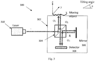
- the imaging system 300 comprises an interferometer module 302 including at least one beam splitter/combiner 304 configured for receiving at least partially coherent light beam, splitting the beam into object and reference beams noted O 1 and R respectively propagating along substantially identical optical paths and at least one mirror arrangement 306 located in the reference beam path and configured for reflecting the reference beam R towards a detector 308 through beam splitter/combiner 304 where it interferes with an object response noted O 3 to interaction with the object beam.
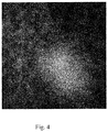
- the imaging system 300 may include a source of at least partially coherent light 310. The speckle pattern and the fringes pattern are shown in Fig. 4 .
- Fig. 5 illustrating an optical configuration of an embodiment of the imaging system 400 of the present invention, in which the mirror arrangement 306 is configured for displacement at a predetermined frequency f 2 to induce controllable temporal modulation of the interference pattern.
- the illumination source 310 may generate pulsed light having a modulation frequency f 1 selected to enable correlation between illumination and detection sessions.
- the secondary speckle patterns created by direct illumination of an object are acquired for extracting tilting information.
- the correlation of each of the sequential speckles images is measured.
- relative tilting movement of the object is extracted.
- the temporal tilting movement of the object is proportional to the change in the speckle pattern.
- an interferometer operated with phase shift measurements provides z-axis information. Therefore, in order to monitor the z-axis vibration interference, behavior measurements were used.
- a modulation of the illumination source can be used.
- the imaging system of the present invention is capable to perform pulsation of the illumination source at frequency f 1 and/or modulation of the interferometer mirror at frequency of f 2 .
- the imaging unit provides an unfocused image of the object in the object plane, a sequence of secondary speckle patterns are collected at the detector plane.
- a speckle pattern has a frequency of ⁇ 1
- fringes of the interference pattern has a frequency of ⁇ 2 . If the illumination source 310 and the interferometric mirror arrangement 306 are modulated at frequencies of f 1 and f 2 respectively, the following is obtained: the fringe would move at a frequency of ⁇ 2 +f 1 +f 2 and the speckle at a frequency of ⁇ 1 +f 1 .
- Fig. 6 The correlation between the illumination and detection sessions is illustrated in Fig. 6 in which spectral replications of the detection sessions are acquired due to the pulses of the laser.
- a low sampling rate detector e.g. even a detector operating at regular video rate (e.g. 50 or 60 fps) can be used (and thus many pixels in space can be used and a large field of view analysis can be performed) since the illumination source performs optical down conversion of the spectral distribution to the low band region (because it realizes optical sampling procedure) and the frequency of the mirror f 2 together with the spatial information allows to separate between the tilting and the axial movements.
- Fig. 6 schematically demonstrates how due to the pulsation of the illumination source 310 high temporal frequencies e.g.
- this embodiment of the imaging system provides a modified interference based configuration for remote sensing of six degrees of freedom of any general movement.
- the imaging system 500 comprises inter alia an illumination source 510 generating an at least partially coherent light beam.
- the imaging system 500 also comprises a beam splitter 504 configured for receiving at least partially coherent light beam, splitting the beam into object and reference beams noted O and R respectively propagating along substantially identical optical paths and a mirror arrangement located in the reference beam path and including in this example three adjustable mirrors noted as 506a and 506b.
- Adjustable mirrors 506a are configured for reflecting the reference beam R towards a camera 509 where it interferes with an object response noted O to interaction with the object beam through a second beam splitter/combiner 505.
- the mirror arrangement can change the length of the reference path in order to calibrate the interferometer with two similar paths and according with its coherence length. Since the at least partially coherent light beam in the reference path gets to the camera 509 directly, while the at least partially coherent light beam in the object path is acquired by reflection from the object, thus the intensities of the at least partially coherent light beams from the two paths on camera 509 are not the same. For that reason a filter 511 may be placed in the reference path to equal the two path intensities of light propagating along the reference and object paths.
- the imaging system 500 also comprises a detector 508.
- camera 509 is configured and operable to monitor the tilting shift by tracking the speckle movement (or imaging the object), while detector 508 is configured and operable to monitor the axial movement of the object. These two functions may be performed by the same imaging element.
- the detector 508 is configured to receive/collect the speckle patterns and the interference fringes in order to perform the movement estimation.
- a pinhole 513 may be used for collecting a portion of the secondary speckle patterns and may be attached to the detector 508.
- the pinhole is of 200 ⁇ m.
- system 500 further comprises a feedback circuit 512 placed between detector 508 downstream of the reference path.
- the feedback circuit 512 is thus placed from the detector 508 back to the reference path and is configured for correcting frequency multiplication. It should be understood that for stabilization of the fringes pattern imaging, the frequency multiplication caused by the number of wavelengths contained in the object path difference should be corrected.
- the feedback circuit 512 comprises a differentiator amplifier through which the output signal from the detector 508 passes with negative feedback.
- the differentiator amplifier may be powered by a DC power supply.
- the output derived signal from the amplifier derived an analogue amplifier driver controls a piezoelectric actuator 507 attached to a controlled mirror 506b of the mirror arrangement 506 in the reference path.
- the controlled mirror movement compensates the instability of the frequency multiplication due to the number of wavelength in the path length changes.
- the system 500 comprises a support surface for supporting the object and applying a periodic stimulation to the object. In this way, a stimulation field of a periodically changing stimulation frequency can be applied to an object.
- the illumination source 510 is controlled to select a coherence length for the at least partially coherent beam to provide a desired ratio between a size of an illumination spot and size of the speckles in a captured set of patterns.
- the system 500 enables the separation between different movements of the various components of the object. More generally, by using a degree of partial coherence and/or a plurality of wavelengths more information about the inspected object (e.g. having a back reflecting surface) may be extracted.
- a degree of partial coherence and/or a plurality of wavelengths more information about the inspected object (e.g. having a back reflecting surface) may be extracted.
- back reflections of the laser beam are originated from the surface of the shirt as well as from the tissue of his body underneath the shirt (e.g. from his chest).
- the technique of the present invention generates such a separation by using a controlled partial coherence of the illumination source 501 (spatial or temporal).
- the coherence length of the at least partially coherent beam may be selected to be shorter than the distance between the tissue and the shirt to prevent the interference between the two different speckle patterns.
- the two different speckle patterns can be separate via image processing as each one of them has different temporal dynamics. This may be implemented by the processing utility 16 shown in Fig. 1 . Therefore, the technique of the invention comprises separating between the moving object and a reflecting surface at least partially surrounding the object by selecting the coherence length of the at least partially coherent electromagnetic beam to be shorter than a typical distance between the object and the reflected surface.
- the technique of the invention comprises separating between the moving object and a reflecting surface at least partially surrounding the object by generating at least two wavelengths having different linear mixture coefficients.
- the illumination source 510 was a laser diode of the firm Photop Suwtech of the type DPGL-2100F having a wavelength of 532 nm and a power of max 300 mW operated with a driver (Photop LDC-2500S);
- the detector 508 was a Si switchable gain detector of the type Thorlabs PDA100A-EC, 340-1100 nm, 2.4 MHz BW, 100 mm2;
- the camera 509 was of the type PixelLink PL-B761U;
- the piezoelectric actuator 507 was a low voltage piezoelectric actuator controlled by an analogue amplifier of the type Piezomechanik SVR 1000-1;
- the DC power supply powering the differentiator amplifier was of the type Lion LE-3003D-3;
- the support surface was a speaker of the type OSC LS13C050, 2 1/4" Diameter, 50 ohm 0.5 Watt controlled by a signal generator (Tektronix AFG1022).
- the system 500 also comprise another mirror for
- an imaging system for monitoring at least one parameter of movement of a moving object comprises an imaging unit comprising a detector having certain detection sessions and a source of at least partially coherent light generating a beam of at least partially coherent light having a predetermined frequency modulation.
- the frequency modulation of the source is selected to overcome the detector limited frame per second rate, due to the increased frequency changes of the interference fringe pattern.
- the frequency modulation of the source is selected with respect to the frequency range of the surface movement of the object.
- the coherent illumination is in the form of pulsed light having a modulation frequency selected to enable correlation between illumination and detection sessions (sampling rate). Therefore, the pulsation of the source allows the detection of fast vibrations by slow camera.
- the laser parameters were as follows: the wavelength was about 532 nm, the power (on detector and camera) was in the range of about 5-13 ⁇ ; the driver current was about 0.35 A; the modulation signal was about 25% on pulse; the frequency range was about 0-220 Hz; the voltage (Pk2Pk) was about 10 V and the offset was about 0 V.
- the detector parameters were as follows: the gain set was about 40 dB, the bandwidth was about 225 kHz; the FFT Offset was about -110 dBV.
- the object parameters were as follows: the object signal was a sinusoidal signal, the frequency range was about 0-220 Hz; the voltage (Pk2Pk) was about 10 V and the offset was about 0 V.
- Figs. 8a-8g The laser modulation results are illustrated in Figs. 8a-8g .
- the high frequency of the object is modulated by the laser frequency to low frequencies.
- Fig. 8a shows the laser frequency at 250Hz and its harmonics
- Figs. 8b-8d show the object frequency, its harmonics and the 50Hz line noise at 120Hz, 170 Hz and220 Hz respectively
- Figs. 8e-8g show the object frequencies with laser modulation at 250 Hz.
- the object frequency is 120 Hz
- Fig. 8f the object frequency is 170 Hz
- Fig. 8g the object frequency is 220 Hz.
- the results show that the high frequency object signal is modulated to low frequencies within the detector frame rate window according to the frequencies difference but the frequencies had many harmonics frequencies due the convolution of the laser modulation.
- an imaging system for receiving an at least partially coherent light beam being indicative of at least one parameter of movement of a moving object
- the system comprises an imaging unit comprising a detector; an interferometric module configured and operable to detect an interference pattern indicative of phase shifts of the object being indicative of temporal changes along a z-axis;
- the interferometric module comprises at least one beam splitter/combiner configured for receiving at least partially coherent light beam, splitting the beam into object and reference beams propagating along substantially identical optical paths; and at least one mirror arrangement located in the reference beam path and configured for reflecting the reference beam towards the detector through the beam splitter/combiner where it interferes with an object response to interaction with the object beam, wherein the at least one mirror arrangement is configured for displacement at a predetermined frequency to induce controllable temporal modulation of the interference pattern.
- the camera parameters were as follows: the exposure time was about 0.2 msec; the frame rate was about 100; the number of frames acquired was about 1000; the scan time was about 10 sec; the signal gain was about 0 dB and the gamma of the camera was about 2.2.
- the mirror arrangement parameters were as follows: the analogue amplifier output voltage was about 180 V; the modulation signal was a saw tooth signal; the frequency range was about 0-220 Hz; the voltage (Pk2Pk) was about 4.9 V and the offset was about 0 mV.
- the object parameters were as follows: the object signal was a sinusoidal signal, the frequency range was about 0-220 Hz; the voltage (Pk2Pk) was about 8 V and the offset was about 0 mV.
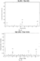
- Figs. 9a-9b The mirror modulation results are illustrated in Figs. 9a-9b .
- the high frequency of the object is modulated by a piezoelectric mirror frequency to low frequencies.
- Fig. 9a shows the object and modulation frequencies and their difference and addition frequencies when the object frequency is 20Hz and the frequency of the piezoelectric mirror arrangement is 22 Hz;
- Fig. 9b shows the difference frequency and the cut frequencies (by 100Hz of the detector) of the object and piezoelectric mirror object frequency when the object frequency is 110Hz and the frequency of the piezoelectric mirror arrangement is 141 Hz.
- the results show that the high frequency object signal is modulated to low frequencies within the detector frame rate window according to the frequencies difference.
- the inventors of the present invention have made some experiment to test the laser and the mirror arrangement modulations together using an open circuit without feedback.
- the laser parameters were as follows: the wavelength was about 532 nm, the power (on detector and camera) was in the range of about 5-13 ⁇ ; the driver current was about 0.35 A; the modulation signal was about 25% on pulse; the frequency range was about 0-220 Hz; the voltage (Pk2Pk) was about 10 V and the offset was about 0 V.
- the detector parameters were as follows: the gain set was about 40 dB, the bandwidth was about 225 kHz; the FFT Offset was about -110 dBV.
- the camera parameters were as follows: the exposure time was about 0.2 msec; the frame rate was about 200; the number of frames acquired was about 1000; the scan time was about 5 sec; the signal gain was about 0 dB and the gamma of the camera was about 2.2.
- the mirror arrangement parameters were as follows: the analogue amplifier output voltage was about 180 V; the modulation signal was a saw tooth signal; the frequency range was about 0-220 Hz; the voltage (Pk2Pk) was about 4.9 V and the offset was about 0 mV.
- the object parameters were as follows: the object signal was a sinusoidal signal, the frequency range was about 0-220 Hz; the voltage (Pk2Pk) was about 10 V and the offset was about 0 V.
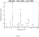
- Fig. 10 The laser and mirror arrangement modulation results are illustrated in Fig. 10 .
- the high frequency of the object is modulated by the laser and the piezoelectric mirror (noted herein below as piezo) frequencies to low frequencies.
- Fig. 10 shows the object and modulation frequencies and their difference and addition frequencies when the object frequency is 67 Hz, the frequency of the piezoelectric mirror arrangement is 18 Hz and the laser modulation frequency is 24 Hz.
- the difference and addition frequencies of the object and the modulation frequencies gave many combination frequencies such as: 6 Hz (laser-piezo), 42 Hz (laser+piezo), 43 Hz (object-laser), 48, 54, 72 Hz (harmonics of laser and piezo frequencies), 85 Hz (object+piezo) etc.
- the results show that the high frequency object signal is modulated to low frequencies within the detector frame rate window according to the frequencies difference.
Description
- The present invention relates to a method and system for monitoring at least one parameter of a moving object.
- For many applications, such as robotics, vehicle navigation, computer game applications, medical applications and other problem domains, it is valuable to be able to track motion comprising 3D position (and optionally also orientation) of a device as it moves in a known environment. Orientation and position of a device is known and may comprise six degrees of freedom (three of translation and three of rotation).
- Existing approaches for tracking 3D position of an object in an environment, such as time of flight camera systems, structured light camera systems, fiducial marker systems, global positioning systems and others are often best suited for coarse levels of detail. Existing equipment for fast and/or fine-grained tracking of objects requires considerable fixed infrastructure and is typically cost-prohibitive for most consumers.
- A speckle pattern is a micro-pattern of illumination generated by a coherent light source, such as a laser, when it passes through a diffuser or when it scatters from a surface which has irregularities larger than the wavelength of the illumination. Streams of laser speckle images are used in some types of computer mice to calculate 2D velocity vectors tracking motion of the mouse. Disparities between corresponding speckles in images of the same speckle pattern taken at different times give information about 2D displacement.
-
DE 41 08 944 A1 describes an interferometric arrangement consisting of a light source and optical elements. An unfocussed image of the object is produced by an imaging system. The coherence length of the illumination is as short as possible but not less than the surface roughness depth. The illumination aperture angle is smaller than the observation aperture angle. A photoreceiver is pref. not larger than the average speckle size. The contrast of the interference in each speckle is pref. separately evaluated whilst the light path difference between the object and the reference beam is modulated. The object point distance or roughness depth is derived from the speckle contrast as a function of the light path difference. -
US 4,913,550 describes an electronic speckle pattern interferometric for measuring the movement of a vibrating body uses a coherent light source to illuminate the body. A television camera receives radiation scattered by the body and from a reference beam to form a speckle pattern. Successive measurements are stored in a frame store and displayed on a monitor. - "Combined fibre optic laser velocimeter and electronic speckle pattern interferometer with a common reference beam" by Valera JD et al, Measurement Science and Technology, IOP, Bristol, GB, vol. 4, no.5, 1 May 1993, pages 578-582 describes a novel optical fibre system, for out-of-plane vibration analysis, comprising the complementary techniques of laser velocimetry and electronic speckle pattern interferometry. The laser velocimeter (LV) and the electronic speckle pattern interferometer (ESPI) share a common reference arm and phase modulator. The LV locks to the motion of a point on the vibrating surface and since the ESPI and LV share a common reference arm, automatic heterodyning of the time-averaged ESPI fringes is achieved.
-
US 2010/226543 describes a method for imaging an object. The method comprises imaging a coherent speckle pattern propagating from an object, using an imaging system being focused on a plane displaced from the object. - The invention relates to a method and system for monitoring at least one parameter of an object, as defined in the appended claims.
- Here, "object" may be a single element, a subject, a body's part of at least one individual people, or a group of elements or subjects or a surface thereof. The body's part may be a passive soft tissue. The object may be a back reflecting surface being uniform or not.
- Generally, a motion of a surface can be split into such components as transversal motion, axial motion, and tilt (the axis connects the surface of interest with the imaging unit). In some embodiments, the technique of the invention has an enhanced sensitivity to the tilt, which on the imager sensing plane (PDA) primarily causes speckle pattern shifting. The transversal motion of the surface of interest causes shifts and changes of the speckle pattern image, but in cases when imaging utilizes focusing on a displaced (e.g. forward or downward displaced) plane (i.e. unfocused image) thus caused shifts are often significantly smaller than the shifts caused by the tilt. In this specific case, the spatial image space transformation is a Fourier transformation. The full change of the parameter of interest is then determined by determining a shift of a speckle pattern in a six-coordinate space. Therefore, the imaging unit is operable to provide an unfocused image of the object in the object plane, collect a sequence of secondary speckle patterns and determine at least one shift between regions of the object which appear in the sequence of secondary speckle patterns, to thereby provide motion data indicative of motion of the object along a tilt dimension and image data in an x-y plane. The unfocused imaging may be performed by the imaging unit configured for imaging the moving object on an image plane, or by another imaging unit being unfocused on the object in the object plane.
- In some embodiments, the system further comprises a pinhole for collecting a portion of the secondary speckle patterns.
- The description discloses an imaging system for monitoring at least one parameter of movement of a moving object, the system comprising an imaging unit comprising a detector having certain detection sessions; a source of at least partially coherent light generates a beam of at least partially coherent light having a predetermined frequency modulation. The frequency modulation of the source is selected to overcome the detector limited frame per second rate, due to the increased frequency changes of the interference fringe pattern. Moreover, the frequency modulation of the source is selected with respect to the frequency range of the surface movement of the object. Preferably, the coherent illumination is in the form of pulsed light having a modulation frequency selected to enable correlation between illumination and detection sessions (sampling rate). Therefore, the pulsation of the source allows the detection of fast vibrations by slow camera.
- According to the present invention, there is provided an imaging system for monitoring at least one parameter of movement of a moving object according to claim 1, the system comprising an imaging unit comprising a detector; an interferometric module configured and operable to detect an interference pattern indicative of phase shifts of the object being indicative of temporal changes along a z-axis; the interferometric module comprises at least one beam splitter/combiner configured for receiving at least partially coherent light beam, splitting the beam into object and reference beams propagating along substantially identical optical paths; and at least one mirror arrangement located in the reference beam path and configured for reflecting the reference beam towards the detector through the beam splitter/combiner where it interferes with an object response to interaction with the object beam, wherein the at least one mirror arrangement is configured for displacement at a predetermined frequency to induce controllable temporal modulation of the interference pattern. The interferometric module provides an interference pattern indicative of temporal changes at a surface of the object in the z-axis. Preferably, a Mach-Zehnder interferometer is used.
- The interferometric module may be a stand alone module of the imaging system or may be integrated in the imaging unit.
- In some embodiments, the system comprises an illumination source generating a beam of at least partially coherent light having a predetermined frequency modulation. The frequency modulation of the source is selected to overcome the detector limited frame per second rate, due to the increased frequency changes of the interference fringe pattern. Moreover, the frequency modulation of the source is selected with respect to the frequency range of the surface movement. Preferably, the coherent illumination is in the form of pulsed light having a modulation frequency selected to enable correlation between illumination and detection sessions (sampling rate). Therefore, the pulsation of the source allows the detection of fast vibrations by slow camera.
- In some embodiments, the system comprises a filter placed in the reference path and configured for equalizing intensities of light propagating along the reference and object paths.
- In some embodiments, the system comprises a feedback circuit placed between the detector downstream of the reference path, the feedback circuit being configured for correcting frequency multiplication.
- In some embodiments, the system is configured such that the tilt and z-axis data are concurrently obtained on the same imaging unit/detector. To this end, the imaging unit utilizes the object path as an imaging channel to produce unfocused image of the object by receiving a reflected secondary speckle pattern originated at the object (due to movement /vibrations in at least a part of the object) and provides image data indicative of the changes in the speckle pattern in the x-y plane, i.e. tilt with respect to x-y plane. Alternatively, the collection of the tilt and z-axis data can be time separated. The mirror of the interferometric module may be controllably moved to induce controllable temporal modulation of the interference pattern. This enables to separate between the tilt and z-axis data in the detected image.
- Thus, the technique provides a detection of a surface movement in the x-y plane having a tilt component with the detection of temporal changes of the surface in the z-axis. The technique of the present invention combines imaging of a coherent speckle pattern of a surface movement with detection of interference changes being indicative of vibrations of the surface in the z-axis at the same scan time. The technique includes imaging of a coherent speckle pattern formed by an object or subject or, generally, a surface of interest. The pattern can be formed by illumination of the still or moving surface of interest by coherent light of a laser or another light source. The surface movement can be for example of vibration type. The vibration can be caused by a sound or vibration itself can produce a sound, thus making the motion of the surface of interest associated with the sound.
- In some embodiments, the system comprises a support surface for supporting the object and applying a periodic stimulation to the object.
- According to another broad aspect of the present invention, there is provided a method for monitoring at least one parameter of movement of a moving object, the method comprises applying a spatial image space transformation to at least one parameter of a movement into geometric relation, by translating different components of six degrees of freedom of movement in a three-dimensional space into a lateral translation; imaging the moving object on an image plane; and generating motion data being indicative of six degrees of freedom of movement.
- According to another broad aspect of the present invention, there is provided a method for monitoring at least one parameter of movement of a moving object as defined in
claim 10. - In some embodiments, the method comprises illuminating the moving object with at least partially coherent electromagnetic beam. A coherence length for the coherent beam may be selected to provide a desired ratio between a size of an illumination spot and size of the speckles in a captured set of patterns.
- In some embodiments, the method comprises applying a stimulation field of a periodically changing stimulation frequency to an object.
- In some embodiments, the method comprises concurrently imaging the interference pattern onto the imaging plane.
- In some embodiments, the method comprises timely separating between the interference pattern and the motion data.
- In some embodiments, the method comprises measuring at least one of velocity and frequency of the moving object along the z-axis.
- In some applications, where the object is located behind certain surface (e.g. individual's body behind the clothes), the coherence length of illumination is selected to be shorter than a typical distance between the object and such surface. Therefore, in some embodiments, the method comprises separating between the moving object and a reflecting surface at least partially surrounding the object by selecting the coherence length of the at least partially coherent electromagnetic beam to be shorter than a typical distance between the object and the reflected surface.
- In order to better understand the subject matter that is disclosed herein and to exemplify how it may be carried out in practice, embodiments will now be described, by way of non-limiting example only, with reference to the accompanying drawings, in which:
-
Fig. 1 represents a schematic illustration of the main modules of an imaging system -
Fig. 2a represents a schematic illustration of the main modules of the imaging system of the present invention; -
Fig. 2b represents a specific and non-limiting schematic illustration of the operation of a possible configuration of the imaging system of the present invention; -
Fig. 3 representing an example of a configuration of an imaging system; -
Fig. 4 shows speckle pattern and the fringes pattern; -
Fig. 5 represents an optical configuration of an embodiment of the imaging system in which the mirror arrangement is configured for displacement at a predetermined frequency to induce controllable temporal modulation of the interference pattern; -
Fig. 6 shows the correlation between illumination and detection sessions in which spectral replications of the detection sessions are acquired due to pulses of the laser; -
Fig. 7 represents a specific and non-limiting example of an imaging system of the present invention; -
Figs. 8a-8g show laser modulation results; -
Figs. 9a-9b show mirror modulation results; and; -
Fig. 10 shows laser and mirror arrangement modulation results. - The position and orientation of a rigid body in space is defined by six degrees of freedom: three components of translation (x-, y-, and z-) and three components of rotation (roll-, pitch-, and yaw-rotations). Generally, a motion of a surface can be split into such components as transversal motion, axial motion, and tilt (the axis connects the surface of interest with the imaging unit). According to some embodiments of the present invention, to monitor at least one parameter of movement of the moving object, an optical transformation is applied to at least one parameter of a movement to provide a geometric relation between the parameter of the movement and a spatial image space, by translating different components of six degrees of freedom of movement in a three-dimensional space into a lateral translation. The moving object is then imaged on an image plane and motion data being indicative of six degrees of freedom of movement is generated. The optical transformation comprises at least one of Fourier transform, circular harmonic transform, Mellin transform, coordinate transform such as e.g. Cartesian (x,y) coordinates into (log(r), θ) when r is a radial coordinate and θ an angular coordinate. Reference is made to
Fig. 1 representing a schematic illustration of the main modules of an imaging system. Theimaging system 100 is aimed at monitoring at least one parameter of movement of a moving object. Thesystem 100 comprises at least oneimaging unit 10 configured and operable for imaging the moving object on an image plane and generating image data indicative of the moving object in an x-y plane. Theimaging unit 10 comprises anoptical transformer 12 configured and operable for applying an optical transformation of at least one parameter of movement into geometric relation between the parameter of the movement and a spatial image space, by translating different components of six degrees of freedom of movement in a three-dimensional space into a lateral translation. Theoptical transformer 12 is configured and operable to convert different movement characteristics into geometric relations. Theoptical transformer 12 is an optical element, placed in the aperture plane of theimaging unit 10 configured to apply an optical transformation and to therefore detect the different components of the movement of the inspected tissue/object. Therefore, theimaging system 100 generates motion data indicative of the six degrees of freedom of movement. In some examples, theoptical transformer 12 applies at least one of Fourier transform, Mellin transform, coordinate transform such as Cartesian coordinates transform into (log(r), θ) when r is a radial coordinate and θ is an angular coordinate or circular harmonic transform. Therefore, the system provides modified optical transformations for remote sensing of six degrees of freedom of any general movement. Theoptical transformer 12 may be a coordinate transformation filter or any general linear optical transformer described for example in Z. Zalevsky and D. Mendlovic, "Optical implementation of the Bode transform," Appl. Opt. 34, 828-831 (1995), Zalevsky, D. Mendlovic and G. Shabtay, "Transformations in optics: Novel perspectives, approaches, applications and implementations," J. of Opt. & Quant. Elect. 34, 1175-1181 (2002), or in D. Sazbon, Z. Zalevsky, E. Rivlin and D. Mendlovic, "Using Fourier/Mellin-based correlators and their fractional versions in navigational tasks," Journal of Pattern Recognition, Vol. 35 (12), pp. 2993-2999 (2002). - In some embodiments, the
imaging unit 10 is selectively operable to provide an unfocused image of the object in the object plane, collect a sequence of secondary speckle patterns and determine at least one shift between regions of the object which appear in the sequence of secondary speckle patterns, to thereby provide motion data indicative of motion of the object along a tilt dimension and image data in an x-y plane. The sequence of secondary speckle patterns is focused on a plane displaced from the moving object. The speckle pattern method is based upon temporal tracking of a secondary reflected speckle by imaging the speckle through properly defocused optics. The tilting changes of the object surface reflect the movement of the speckle pattern in the x-y plane. In this specific case, the spatial image space transformation is a Fourier transformation (far field defocused imaging) which converts tilting changes into movement of the speckle patterns. - Alternatively, the
system 100 comprises a specklepattern collecting unit 14 being unfocused on the object in the object plane and collecting a plurality of sequential secondary speckle patterns thereby generating data indicative of an image of the object in an x-y plane and determining at least one shift between regions of the object which appear in at least first and second images of the object, to thereby provide data indicative of motion of the object along a tilt dimension and image data in an x-y plane. - The
imaging unit 10 may comprise aprocessing utility 16 configured to determine the shift between the sequence of secondary speckle patterns and provide motion data indicative of motion of the object along a tilt dimension and image data in an x-y plane. Theprocessing utility 16 may be a DSP, microcontroller, FPGA, ASIC, etc., or any other conventional and/or dedicated computing unit/system. The term "processing utility" should be expansively construed to cover any kind of electronic device with data processing capabilities, including, by way of non-limiting example, personal computers, servers, computing systems, communication devices, processors (e.g. digital signal processor (DSP), microcontrollers, field programmable gate array (FPGA), application specific integrated circuit (ASIC), etc.) and other electronic computing devices. The processor utility may comprise a general-purpose computer processor, which is programmed in software to carry out the functions described hereinbelow. Although processingutility 16 is shown inFig. 1 , by way of example, as an integrated unit of theimaging unit 10, some or all of the processing functions ofprocessing utility 16 may be performed by suitable dedicated circuitry within the housing of theimaging unit 10 or otherwise associated with theimaging unit 10 or may be a separate stand alone utility. Unless specifically stated otherwise, as apparent from the following discussions, it is appreciated that throughout the specification discussions utilizing terms such as "processing", "computing", "calculating", "determining", "comparing" or the like, refer to the action and/or processes of a computer that manipulate and/or transform data into other data, the data represented as physical, e.g. such as electronic, quantities. Also, operations in accordance with the teachings herein may be performed by a computer specially constructed for the desired purposes or by a general purpose computer specially configured for the desired purpose by a computer program stored in a computer readable storage medium. The software may be downloaded to processingutility 16 in electronic form, over a network, for example, or it may alternatively be provided on tangible media, such as optical, magnetic, or electronic memory media. Alternatively or additionally, some or all of the functions of theprocessing unit 16 may be implemented in dedicated hardware, such as a custom or semi-custom integrated circuit or a programmable digital signal processor (DSP). - Therefore, the exemplary system and method provide a remote sensing of six degrees of freedom of any general movement. As described above, the
imaging unit 10 or the specklepattern collecting unit 14 are selectively operable to provide an unfocused image of the object in the object plane (far field imaging). Theprocessing utility 16 analyses the temporal changes of the speckle patterns and convert the movement of the speckles into the tilting information of the movement while the x-y information as well as the z-axis movement will not modify the speckle patterns. On the other hand if focused image of the object is performed by the imaging unit 10 (not speckles but regular imaging), then the x-y movement and probably also the z-axis movement (depends on the scale of the image) can be determined. In some examples, theimaging system 100 provides a modified sensing system having two image channels having both a defocused image in which the speckle patterns are analyzed and a regular focused image of the object (regular image and not speckle patterns analysis). The combination of the far field speckle pattern and of a near field image (use of two images) provides the capability to extract more information about the movement characteristics. The near field image gives information about movement in the x-y plane and possible also about z-axis movement and the far field speckle pattern analysis gives angular tilting dimension. - Another technique to monitor at least one parameter of movement of the moving object comprises imaging the moving object on an image plane; detecting an interference pattern indicative of phase shifts of the object being indicative of temporal changes along a z-axis; and; controllably inducing controllable temporal modulation of the interference pattern. In this connection, reference is made to
Fig. 2a representing a schematic illustration of the main modules of the imaging system of the present invention, according to another broad aspect of the present invention. Theimaging system 200 comprises animaging unit 20 comprising adetector 22 and aninterferometric module 24 configured and operable to detect an interference pattern indicative of phase shifts of the object being indicative of temporal changes along a z-axis. In order to achieve a full surface movement data, theinterferometric module 24 is used to detect the temporal changes of the surface in the z-axis. Although, for the sake of simplicity theinterferometric module 24 is represented as a stand alone unit, which may comprise its own detector as illustrated for example inFig. 3 , theinterferometric module 24 may be integrated with theimaging unit 20 such that the interference pattern is concurrently imaged onto an imaging plane of theimaging unit 20. Therefore, in some embodiments, imagingunit 20 comprisesinterferometric module 24. A Mach-Zehnder interferometer configuration can be used. The at least partially coherent light beam is split into two similar paths when only one path is reflected from the moving object. The result is phase shifts between the two beams caused by a change in length of one of the paths. Those phase shifts create the interference pattern (fringes). The vibration of the surface in the z-axis changes the path length of one of the Mach-Zehnder laser paths. These changes reflect in the interference pattern (fringes) of the two joined beams on the detector and camera plane. The number of wavelengths contained in the path's length difference changes the fringes oscillating frequency. Using laser Doppler vibrometer (LDV) technique the velocity of the object surface vibration in the z-axis is measured. The vibration velocity and frequency are extracted from the Doppler shift of the reflected partially coherent beam due to the motion of the surface as will be detailed further below. Therefore, the technique measures at least one of velocity and frequency of the moving object along the z-axis to thereby enable to timely separating between the interference pattern and the motion data. - Reference is made to
Fig. 2b , representing a specific and non-limiting schematic illustration of the operation of a possible configuration of the imaging system In this configuration, the imaging system receives an at least partially coherent light beam being indicative of at least one parameter of movement of a moving object. The at least partially coherent light beam is separated in two paths: an object path and a reference path. The at least partially coherent light beam of the object path is received by the imaging unit being selectively operable to provide an unfocused image of the object in the object plane which generates motion data indicative of motion of the object along a tilt dimension. As described above, the method comprises positioning the imaging unit to provide an unfocused image of the object in the object plane and collecting at the imaging unit a sequence of secondary speckle patterns and determining at least one shift between regions of the object appearing in the sequence of secondary speckle patterns. The imaging unit is thus operable to provide an unfocused image of the object in the object plane, collect a sequence of secondary speckle patterns and determine at least one shift between regions of the object which appear in the sequence of secondary speckle patterns, to thereby provide motion data indicative of motion of the object along a tilt dimension and image data in an x-y plane. The sequence of secondary speckle patterns is focused on a plane displaced from the moving object. The speckle pattern method is based upon temporal tracking of a secondary reflected speckle by imaging the speckle through properly defocused optics. The tilting changes of the object surface reflect the movement of the speckle pattern in the x-y plane. The object path and the reference path are introduced into an interferometric module configured and operable to detect an interference pattern indicative of phase shifts of the object being indicative of temporal changes along a z-axis. - Reference is made to
Fig. 3 representing an example of a configuration of the imaging system according to some embodiments of the present invention. In this example, theimaging system 300 comprises aninterferometer module 302 including at least one beam splitter/combiner 304 configured for receiving at least partially coherent light beam, splitting the beam into object and reference beams noted O1 and R respectively propagating along substantially identical optical paths and at least onemirror arrangement 306 located in the reference beam path and configured for reflecting the reference beam R towards adetector 308 through beam splitter/combiner 304 where it interferes with an object response noted O3 to interaction with the object beam. Theimaging system 300 may include a source of at least partiallycoherent light 310. The speckle pattern and the fringes pattern are shown inFig. 4 . - Reference is made to
Fig. 5 illustrating an optical configuration of an embodiment of theimaging system 400 of the present invention, in which themirror arrangement 306 is configured for displacement at a predetermined frequency f2 to induce controllable temporal modulation of the interference pattern. Additionally or alternatively, theillumination source 310 may generate pulsed light having a modulation frequency f1 selected to enable correlation between illumination and detection sessions. - In this connection, it should be understood that as described above, the secondary speckle patterns created by direct illumination of an object are acquired for extracting tilting information. In order to monitor the tilting vibration, the correlation of each of the sequential speckles images is measured. By analyzing the changes in the correlation peak position, relative tilting movement of the object is extracted. The relative shift β of the speckle pattern is proportional to the change in the spatial position of the speckle pattern due to the object temporal tilting movement:

- Moreover, an interferometer operated with phase shift measurements provides z-axis information. Therefore, in order to monitor the z-axis vibration interference, behavior measurements were used. The constructive and destructive interferences pattern of the fringes imaging is according to the length difference between the two paths:

- This situation of frequency multiplication leads to a problem of detector limited frame rate. In order to solve this problem, a modulation of the illumination source can be used. The modulation frequency is such that the difference between it and the object frequency bandwidth is in the detector limited frame rate:

- Therefore the imaging system of the present invention is capable to perform pulsation of the illumination source at frequency f1 and/or modulation of the interferometer mirror at frequency of f2. As described above, since the imaging unit provides an unfocused image of the object in the object plane, a sequence of secondary speckle patterns are collected at the detector plane. It should be understood that generally a speckle pattern has a frequency of µ1 and fringes of the interference pattern has a frequency of µ2. If the
illumination source 310 and theinterferometric mirror arrangement 306 are modulated at frequencies of f1 and f2 respectively, the following is obtained: the fringe would move at a frequency of µ2+f1+f2 and the speckle at a frequency of µ1+f1. The correlation between the illumination and detection sessions is illustrated inFig. 6 in which spectral replications of the detection sessions are acquired due to the pulses of the laser. The result shows that a low sampling rate detector e.g. even a detector operating at regular video rate (e.g. 50 or 60 fps) can be used (and thus many pixels in space can be used and a large field of view analysis can be performed) since the illumination source performs optical down conversion of the spectral distribution to the low band region (because it realizes optical sampling procedure) and the frequency of the mirror f2 together with the spatial information allows to separate between the tilting and the axial movements.Fig. 6 schematically demonstrates how due to the pulsation of theillumination source 310 high temporal frequencies e.g. frequencies of few KHz can be down converted to allow their sampling with a slow rate detector e.g. one that operates at rate of few hundred of Hz. It can be seen how the high frequencies are folded into the low frequency spectral band sampled by the detector. Therefore, this embodiment of the imaging system provides a modified interference based configuration for remote sensing of six degrees of freedom of any general movement. - Reference is made to
Fig. 7 representing a specific and non-limiting example of an imaging system of the present invention. Theimaging system 500 comprises inter alia anillumination source 510 generating an at least partially coherent light beam. In this example, theimaging system 500 also comprises abeam splitter 504 configured for receiving at least partially coherent light beam, splitting the beam into object and reference beams noted O and R respectively propagating along substantially identical optical paths and a mirror arrangement located in the reference beam path and including in this example three adjustable mirrors noted as 506a and 506b. Adjustable mirrors 506a are configured for reflecting the reference beam R towards acamera 509 where it interferes with an object response noted O to interaction with the object beam through a second beam splitter/combiner 505. The mirror arrangement can change the length of the reference path in order to calibrate the interferometer with two similar paths and according with its coherence length. Since the at least partially coherent light beam in the reference path gets to thecamera 509 directly, while the at least partially coherent light beam in the object path is acquired by reflection from the object, thus the intensities of the at least partially coherent light beams from the two paths oncamera 509 are not the same. For that reason afilter 511 may be placed in the reference path to equal the two path intensities of light propagating along the reference and object paths. Theimaging system 500 also comprises adetector 508. It should be noted that in this specific and non-limiting example,camera 509 is configured and operable to monitor the tilting shift by tracking the speckle movement (or imaging the object), whiledetector 508 is configured and operable to monitor the axial movement of the object. These two functions may be performed by the same imaging element. Thedetector 508 is configured to receive/collect the speckle patterns and the interference fringes in order to perform the movement estimation. In order to detect only small area of the speckle pattern and the fringes pattern, apinhole 513 may be used for collecting a portion of the secondary speckle patterns and may be attached to thedetector 508. In this example the pinhole is of 200 µm. In this example,system 500 further comprises afeedback circuit 512 placed betweendetector 508 downstream of the reference path.Feedback circuit 512 is thus placed from thedetector 508 back to the reference path and is configured for correcting frequency multiplication. It should be understood that for stabilization of the fringes pattern imaging, the frequency multiplication caused by the number of wavelengths contained in the object path difference should be corrected. Thefeedback circuit 512 comprises a differentiator amplifier through which the output signal from thedetector 508 passes with negative feedback. The differentiator amplifier may be powered by a DC power supply. The output derived signal from the amplifier derived an analogue amplifier driver controls apiezoelectric actuator 507 attached to a controlledmirror 506b of the mirror arrangement 506 in the reference path. The controlled mirror movement compensates the instability of the frequency multiplication due to the number of wavelength in the path length changes. In some embodiments, thesystem 500 comprises a support surface for supporting the object and applying a periodic stimulation to the object. In this way, a stimulation field of a periodically changing stimulation frequency can be applied to an object. - In some embodiments, the
illumination source 510 is controlled to select a coherence length for the at least partially coherent beam to provide a desired ratio between a size of an illumination spot and size of the speckles in a captured set of patterns. In this way, thesystem 500 enables the separation between different movements of the various components of the object. More generally, by using a degree of partial coherence and/or a plurality of wavelengths more information about the inspected object (e.g. having a back reflecting surface) may be extracted. In this connection, it should be understood that when, for example, an inspected subject wears clothing such as a shirt, back reflections of the laser beam are originated from the surface of the shirt as well as from the tissue of his body underneath the shirt (e.g. from his chest). Each of such back reflections produces its own speckle pattern and since each one of the two back reflecting surfaces can move independently, the two different speckle patterns and their time varying characteristics mix and do not allow proper analysis or separation between the movement of the two different types of surfaces. The technique of the present invention generates such a separation by using a controlled partial coherence of the illumination source 501 (spatial or temporal). The coherence length of the at least partially coherent beam may be selected to be shorter than the distance between the tissue and the shirt to prevent the interference between the two different speckle patterns. The two different speckle patterns can be separate via image processing as each one of them has different temporal dynamics. This may be implemented by theprocessing utility 16 shown inFig. 1 . Therefore, the technique of the invention comprises separating between the moving object and a reflecting surface at least partially surrounding the object by selecting the coherence length of the at least partially coherent electromagnetic beam to be shorter than a typical distance between the object and the reflected surface. - Alternatively or additionally two or more wavelengths may be used. Since each wavelength has a different penetration depth into a tissue or a shirt, the speckle patterns obtained at each one of the two or more wavelengths have different mixture. As different linear mixture coefficients exist for each wavelength, the two different types of patterns (coming from the tissue and coming from the shirt) are separable via image processing after capturing sufficient time varying information. Therefore, the technique of the invention comprises separating between the moving object and a reflecting surface at least partially surrounding the object by generating at least two wavelengths having different linear mixture coefficients.
- In the set up tested by the inventors of the present invention, the
illumination source 510 was a laser diode of the firm Photop Suwtech of the type DPGL-2100F having a wavelength of 532 nm and a power ofmax 300 mW operated with a driver (Photop LDC-2500S); thedetector 508 was a Si switchable gain detector of the type Thorlabs PDA100A-EC, 340-1100 nm, 2.4 MHz BW, 100 mm2; thecamera 509 was of the type PixelLink PL-B761U; thepiezoelectric actuator 507 was a low voltage piezoelectric actuator controlled by an analogue amplifier of the type Piezomechanik SVR 1000-1; the DC power supply powering the differentiator amplifier was of the type Lion LE-3003D-3; the support surface was a speaker of the type OSC LS13C050, 2 1/4" Diameter, 50 ohm 0.5 Watt controlled by a signal generator (Tektronix AFG1022). Thesystem 500 also comprise another mirror for redirecting the object beam, three lenses for focusing the reference and object beams, two xyz stages, one x stage and dual neutral-density (ND) filter wheel. - The inventors of the present invention have made some experiment to test the illumination source frequency modulation using an open circuit without feedback. As described above, according to a broad aspect of the present invention, there is provided an imaging system for monitoring at least one parameter of movement of a moving object, the system comprises an imaging unit comprising a detector having certain detection sessions and a source of at least partially coherent light generating a beam of at least partially coherent light having a predetermined frequency modulation. The frequency modulation of the source is selected to overcome the detector limited frame per second rate, due to the increased frequency changes of the interference fringe pattern. Moreover, the frequency modulation of the source is selected with respect to the frequency range of the surface movement of the object. Preferably, the coherent illumination is in the form of pulsed light having a modulation frequency selected to enable correlation between illumination and detection sessions (sampling rate). Therefore, the pulsation of the source allows the detection of fast vibrations by slow camera. The laser parameters were as follows: the wavelength was about 532 nm, the power (on detector and camera) was in the range of about 5-13 µ; the driver current was about 0.35 A; the modulation signal was about 25% on pulse; the frequency range was about 0-220 Hz; the voltage (Pk2Pk) was about 10 V and the offset was about 0 V. The detector parameters were as follows: the gain set was about 40 dB, the bandwidth was about 225 kHz; the FFT Offset was about -110 dBV. The object parameters were as follows: the object signal was a sinusoidal signal, the frequency range was about 0-220 Hz; the voltage (Pk2Pk) was about 10 V and the offset was about 0 V.
- The laser modulation results are illustrated in
Figs. 8a-8g . In these experiments, the high frequency of the object is modulated by the laser frequency to low frequencies. In particular,Fig. 8a shows the laser frequency at 250Hz and its harmonics;Figs. 8b-8d show the object frequency, its harmonics and the 50Hz line noise at 120Hz, 170 Hz and220 Hz respectively;Figs. 8e-8g show the object frequencies with laser modulation at 250 Hz. In particular inFig. 8e the object frequency is 120 Hz, inFig. 8f the object frequency is 170 Hz and inFig. 8g the object frequency is 220 Hz. The results show that the high frequency object signal is modulated to low frequencies within the detector frame rate window according to the frequencies difference but the frequencies had many harmonics frequencies due the convolution of the laser modulation. - The inventors of the present invention have made some experiment to test the mirror arrangement modulation using an open circuit without feedback. As described above, according to a broad aspect of the present invention, there is provided an imaging system for receiving an at least partially coherent light beam being indicative of at least one parameter of movement of a moving object, the system comprises an imaging unit comprising a detector; an interferometric module configured and operable to detect an interference pattern indicative of phase shifts of the object being indicative of temporal changes along a z-axis; the interferometric module comprises at least one beam splitter/combiner configured for receiving at least partially coherent light beam, splitting the beam into object and reference beams propagating along substantially identical optical paths; and at least one mirror arrangement located in the reference beam path and configured for reflecting the reference beam towards the detector through the beam splitter/combiner where it interferes with an object response to interaction with the object beam, wherein the at least one mirror arrangement is configured for displacement at a predetermined frequency to induce controllable temporal modulation of the interference pattern. The camera parameters were as follows: the exposure time was about 0.2 msec; the frame rate was about 100; the number of frames acquired was about 1000; the scan time was about 10 sec; the signal gain was about 0 dB and the gamma of the camera was about 2.2. The mirror arrangement parameters were as follows: the analogue amplifier output voltage was about 180 V; the modulation signal was a saw tooth signal; the frequency range was about 0-220 Hz; the voltage (Pk2Pk) was about 4.9 V and the offset was about 0 mV. The object parameters were as follows: the object signal was a sinusoidal signal, the frequency range was about 0-220 Hz; the voltage (Pk2Pk) was about 8 V and the offset was about 0 mV.
- The mirror modulation results are illustrated in
Figs. 9a-9b . In these experiments, the high frequency of the object is modulated by a piezoelectric mirror frequency to low frequencies. In particular,Fig. 9a shows the object and modulation frequencies and their difference and addition frequencies when the object frequency is 20Hz and the frequency of the piezoelectric mirror arrangement is 22 Hz;Fig. 9b shows the difference frequency and the cut frequencies (by 100Hz of the detector) of the object and piezoelectric mirror object frequency when the object frequency is 110Hz and the frequency of the piezoelectric mirror arrangement is 141 Hz. The results show that the high frequency object signal is modulated to low frequencies within the detector frame rate window according to the frequencies difference. - The inventors of the present invention have made some experiment to test the laser and the mirror arrangement modulations together using an open circuit without feedback. The laser parameters were as follows: the wavelength was about 532 nm, the power (on detector and camera) was in the range of about 5-13 µ; the driver current was about 0.35 A; the modulation signal was about 25% on pulse; the frequency range was about 0-220 Hz; the voltage (Pk2Pk) was about 10 V and the offset was about 0 V. The detector parameters were as follows: the gain set was about 40 dB, the bandwidth was about 225 kHz; the FFT Offset was about -110 dBV. The camera parameters were as follows: the exposure time was about 0.2 msec; the frame rate was about 200; the number of frames acquired was about 1000; the scan time was about 5 sec; the signal gain was about 0 dB and the gamma of the camera was about 2.2. The mirror arrangement parameters were as follows: the analogue amplifier output voltage was about 180 V; the modulation signal was a saw tooth signal; the frequency range was about 0-220 Hz; the voltage (Pk2Pk) was about 4.9 V and the offset was about 0 mV. The object parameters were as follows: the object signal was a sinusoidal signal, the frequency range was about 0-220 Hz; the voltage (Pk2Pk) was about 10 V and the offset was about 0 V.
- The laser and mirror arrangement modulation results are illustrated in
Fig. 10 . The high frequency of the object is modulated by the laser and the piezoelectric mirror (noted herein below as piezo) frequencies to low frequencies.Fig. 10 shows the object and modulation frequencies and their difference and addition frequencies when the object frequency is 67 Hz, the frequency of the piezoelectric mirror arrangement is 18 Hz and the laser modulation frequency is 24 Hz. As illustrated in the figure, the difference and addition frequencies of the object and the modulation frequencies gave many combination frequencies such as: 6 Hz (laser-piezo), 42 Hz (laser+piezo), 43 Hz (object-laser), 48, 54, 72 Hz (harmonics of laser and piezo frequencies), 85 Hz (object+piezo) etc. The results show that the high frequency object signal is modulated to low frequencies within the detector frame rate window according to the frequencies difference.
Claims (17)
- An imaging system (100; 200; 300; 400; 500) for receiving an at least partially coherent light beam being indicative of at least one parameter of movement of a moving object, the system comprising:an imaging unit (10; 20) comprising a detector (22; 308); wherein said imaging unit is selectively operable to provide an unfocused image of the object in the object plane, collect a sequence of secondary speckle patterns and determine at least one shift between regions of the object which appear in the sequence of secondary speckle patterns, to thereby provide motion data indicative of motion of the object along a tilt dimension and image data in an x-y plane;an interferometric module (24;302) configured and operable to detect an interference pattern indicative of phase shifts of the object being indicative of temporal changes along a z-axis; wherein said interferometric module comprises at least one beam splitter/combiner (304; 504) configured for receiving at least partially coherent light beam, splitting the beam into first object and reference beams; andat least one mirror arrangement (306; 506) located in the reference beam path and configured for reflecting the reference beam towards the detector through said beam splitter/combiner where the reference beam interferes with a second object beam being indicative of an object response to interaction with the first object beam, wherein said at least one mirror arrangement is configured for displacement at a predetermined frequency to induce controllable temporal modulation of the interference pattern; said interferometric module being configured such that the object and reference beams propagate along optical paths having a substantially identical path length.
- The system of claim 1, comprising a source (310; 510) of at least partially coherent light.
- The system of claim 2, wherein said source generates pulsed light having a modulation frequency selected to enable correlation between illumination and detection sessions.
- The system of any one of claims 1 to 3, further comprising a filter (511) placed in the reference beam path and configured for equalizing intensities of light propagating along the reference beam and first object beam paths.
- The system of any one of claims 1 to 4, further comprising a feedback circuit (512) placed between the detector downstream of the reference beam path, said feedback circuit being configured for correcting frequency multiplication.
- The system of any one of claims 1 to 5, wherein said imaging unit comprises said interferometric module configured and operable to collect the interference pattern.
- The system of any one of claims 1 to 6, comprising a support surface for supporting the object and applying a periodic stimulation to the object.
- The system of any one of claims 1 to 7, being configured for monitoring at least one parameter of movement of a moving object, wherein said imaging unit is configured and operable for imaging the moving object on an image plane and generating image data indicative of the moving object in an x-y plane; wherein said imaging unit is configured and operable for applying an optical transformation of at least one parameter of movement into geometric relation between the parameter of the movement and a spatial image space, by translating different components of six degrees of freedom of movement in a three-dimensional space into a lateral translation; said imaging system generating motion data indicative of the six degrees of freedom of movement.
- The system of any one of claims 1 to 8, further comprising a pinhole for collecting a portion of the secondary speckle patterns.
- A method for monitoring at least one parameter of movement of a moving object, the method comprising:splitting at least one partially coherent light beam into a first object and reference beams along two similar paths;receiving a second object beam being reflected from the moving object;imaging the moving object on an image plane;positioning an imaging unit (10; 20) in a first optical path and collecting at the imaging unit a sequence of secondary speckle patterns; wherein said sequence of secondary speckle patterns is focused on a plane displaced from the moving object;determining at least one shift between regions of the object appearing in the sequence of secondary speckle patterns;detecting an interference pattern indicative of phase shifts of the object being indicative of temporal changes along a z-axis; and;inducing controllable temporal modulation of the interference pattern.
- The method of claim 10, comprising illuminating the moving object with at least partially coherent electromagnetic beam.
- The method of claim 11, comprising selecting a coherence length for the coherent beam to provide a desired ratio between a size of an illumination spot and size of the speckles in a captured set of patterns.
- The method of any one of claims 10 to 12, comprising applying a stimulation field of a periodically changing stimulation frequency to an object.
- The method of any one of claims 10 to 13, comprising concurrently imaging the interference pattern onto the imaging plane.
- The method of any one of claims 10 to 14, comprising separating between the interference pattern and the motion data being concurrently imaged onto the imaging plane by providing a temporal modulation to the interference pattern.
- The method of any one of claims 10 to 15, comprising measuring at least one of velocity and frequency of the moving object along the z-axis.
- The method of any one of claims 10 to 16, comprising separating between the moving object and a reflecting surface at least partially surrounding the object by selecting the coherence length of said at least one partially coherent light beam to be shorter than a typical distance between the object and the reflected surface.
Applications Claiming Priority (2)
| Application Number | Priority Date | Filing Date | Title |
|---|---|---|---|
| US201662299598P | 2016-02-25 | 2016-02-25 | |
| PCT/IL2017/050146 WO2017145145A1 (en) | 2016-02-25 | 2017-02-07 | A method and system for monitoring parameters of a moving object |
Publications (3)
| Publication Number | Publication Date |
|---|---|
| EP3420324A1 EP3420324A1 (en) | 2019-01-02 |
| EP3420324A4 EP3420324A4 (en) | 2019-10-30 |
| EP3420324B1 true EP3420324B1 (en) | 2021-03-24 |
Family
ID=59684831
Family Applications (1)
| Application Number | Title | Priority Date | Filing Date |
|---|---|---|---|
| EP17755938.2A Active EP3420324B1 (en) | 2016-02-25 | 2017-02-07 | A method and system for monitoring parameters of a moving object |
Country Status (5)
| Country | Link |
|---|---|
| US (1) | US10883818B2 (en) |
| EP (1) | EP3420324B1 (en) |
| JP (1) | JP2019507871A (en) |
| CN (1) | CN108780004A (en) |
| WO (1) | WO2017145145A1 (en) |
Families Citing this family (9)
| Publication number | Priority date | Publication date | Assignee | Title |
|---|---|---|---|---|
| NL2018857B1 (en) | 2017-05-05 | 2018-11-09 | Illumina Inc | Systems and methods for improved focus tracking using a light source configuration |
| NL2018854B1 (en) | 2017-05-05 | 2018-11-14 | Illumina Inc | Systems and methodes for improved focus tracking using blocking structures |
| NL2018853B1 (en) * | 2017-05-05 | 2018-11-14 | Illumina Inc | Systems and methods for improved focus tracking using a hybrid mode light source |
| DE102018113979A1 (en) * | 2018-06-12 | 2019-12-12 | Fraunhofer-Gesellschaft zur Förderung der angewandten Forschung e.V. | Device and method for the interferometric measurement of a surface of a moving test object |
| US20220039679A1 (en) * | 2018-11-27 | 2022-02-10 | ContinUse Biometrics Ltd. | System and method for remote monitoring of biomedical parameters |
| IL273248B2 (en) * | 2019-03-19 | 2023-05-01 | Continuse Biometrics Ltd | System and method for optical monitoring using symmetry condition of light field |
| IL278987A (en) * | 2019-12-05 | 2021-06-30 | Continuse Biometrics Ltd | System and method for passively monitoring a sample |
| CN111238419B (en) * | 2020-01-20 | 2021-10-01 | 中车齐齐哈尔车辆有限公司 | Detection device and detection method for flatness of sliding valve pair of brake valve |
| CN113465639B (en) * | 2021-06-28 | 2022-03-25 | 浙江大学 | Method and system for detecting object motion by using space-time differentiator based on optical structure |
Family Cites Families (22)
| Publication number | Priority date | Publication date | Assignee | Title |
|---|---|---|---|---|
| GB8522820D0 (en) | 1985-09-16 | 1985-10-23 | Montgomery P C | Interferometric measurement |
| JPH07113533B2 (en) | 1990-11-30 | 1995-12-06 | 浜松ホトニクス株式会社 | Optical deformation amount measuring device |
| DE4108944A1 (en) | 1991-03-19 | 1992-09-24 | Haeusler Gerd | Contactless measurement of surface shape of diffusely scattering objects e.g. semiconductor wafers - using interferometric arrangement for three=dimensional measurement with minimal coherence length and illumination aperture angle less than observation aperture angle |
| JP2538456B2 (en) * | 1991-08-12 | 1996-09-25 | 浜松ホトニクス株式会社 | Optical displacement measuring device |
| DE4427692A1 (en) * | 1994-08-04 | 1996-02-08 | Bayerische Motoren Werke Ag | Method for determining the vibration behavior of a body |
| AU7424798A (en) * | 1997-05-16 | 1998-12-11 | Forskningscenter Riso | Method and apparatus for determining angular displacement, surface translation , and twist |
| US5907404A (en) * | 1997-09-08 | 1999-05-25 | Erim International, Inc. | Multiple wavelength image plane interferometry |
| WO1999046602A1 (en) | 1998-03-09 | 1999-09-16 | Gou Lite Ltd. | Optical translation measurement |
| GB2377754B (en) | 2001-06-09 | 2005-08-17 | Anthony Gerald Booth | Movement detection apparatus and method |
| JP4142532B2 (en) * | 2003-09-02 | 2008-09-03 | シャープ株式会社 | Optical speedometer, displacement information measuring device, and conveyance processing device |
| JP4324507B2 (en) * | 2004-04-20 | 2009-09-02 | 浄史 松田 | Vibration measuring device |
| US7844083B2 (en) | 2004-06-18 | 2010-11-30 | Kyushu Institute Of Technology | Method for acquiring personal identification data, personal identification method, apparatus for acquiring personal identification data, and personal identification apparatus |
| GB2416835C (en) | 2004-08-04 | 2013-11-06 | Statoil Asa | Method and apparatus for studying surfaces |
| US7498811B2 (en) | 2005-11-16 | 2009-03-03 | Macfarlane Duncan L | Apparatus and method for patient movement tracking |
| JP4769952B2 (en) | 2006-02-22 | 2011-09-07 | 国立大学法人九州工業大学 | Personal authentication method and personal authentication device using fingertip blood flow measurement by laser light |
| IL184868A0 (en) | 2007-07-26 | 2008-03-20 | Univ Bar Ilan | Motion detection system and method |
| EP2879568A1 (en) * | 2012-08-01 | 2015-06-10 | Bar Ilan University | Method and system for non-invasively monitoring biological or biochemical parameters of individual |
| CN104730279B (en) * | 2013-12-20 | 2018-04-10 | 中国工程物理研究院激光聚变研究中心 | A kind of chirped pulse velocity interferometer |
| CN103941040B (en) * | 2014-04-23 | 2016-04-27 | 浙江大学 | Based on the device and method of the rear orientation light sense acceleration of nanoparticle detection |
| CN103983341B (en) | 2014-05-20 | 2017-09-22 | 厦门大学 | A kind of high-precision laser speckle microvibration measuring system and measuring method |
| CN104457581B (en) | 2014-08-28 | 2017-03-22 | 深圳奥比中光科技有限公司 | Overall Z-axis displacement measuring system |
| CN104776907A (en) | 2015-04-30 | 2015-07-15 | 杭州电子科技大学 | Vibration detection method based on multi-point laser speckle extreme value tracking |
-
2017
- 2017-02-07 EP EP17755938.2A patent/EP3420324B1/en active Active
- 2017-02-07 JP JP2018543184A patent/JP2019507871A/en active Pending
- 2017-02-07 US US16/078,810 patent/US10883818B2/en active Active
- 2017-02-07 CN CN201780013631.9A patent/CN108780004A/en active Pending
- 2017-02-07 WO PCT/IL2017/050146 patent/WO2017145145A1/en active Application Filing
Non-Patent Citations (1)
| Title |
|---|
| None * |
Also Published As
| Publication number | Publication date |
|---|---|
| CN108780004A (en) | 2018-11-09 |
| EP3420324A1 (en) | 2019-01-02 |
| JP2019507871A (en) | 2019-03-22 |
| EP3420324A4 (en) | 2019-10-30 |
| US20190063898A1 (en) | 2019-02-28 |
| WO2017145145A1 (en) | 2017-08-31 |
| US10883818B2 (en) | 2021-01-05 |
Similar Documents
| Publication | Publication Date | Title |
|---|---|---|
| EP3420324B1 (en) | A method and system for monitoring parameters of a moving object | |
| Rembe et al. | Measuring MEMS in motion by laser Doppler vibrometry | |
| US6198540B1 (en) | Optical coherence tomography have plural reference beams of differing modulations | |
| US9995761B2 (en) | Method for simultaneous observation of three degrees of vibrational freedom using single heterodyne beam | |
| US7245383B2 (en) | Optical image measuring apparatus for obtaining a signal intensity and spatial phase distribution of interference light | |
| US20050219544A1 (en) | Optical image measuring apparatus | |
| Barone et al. | Low-frame-rate single camera system for 3D full-field high-frequency vibration measurements | |
| US7954948B2 (en) | Optical tomographic imaging method and apparatus | |
| JP2006112864A (en) | Optical image measuring instrument and method | |
| JP2011053224A (en) | Apparatus and method for surface contour measurement | |
| JP4512822B2 (en) | Line condensing type Fourier domain interference shape measuring device | |
| US11867611B2 (en) | Optical-interference analysis | |
| JP2010279508A (en) | Optical image measuring device | |
| JP2006250849A (en) | Optical image measuring method using light coherence tomography apparatus and optical image measuring device | |
| JP2003529063A (en) | Vibration measurement method and interferometer | |
| JP3934131B2 (en) | Coaxial spatial optical coherence tomographic image measurement device | |
| Wang et al. | Additive-subtractive speckle interferometry: extraction of phase data in noisy environments | |
| KR101263326B1 (en) | Heterodyne Optical Coherence Tomography using an AOTF | |
| JP5258052B2 (en) | Shape measuring method and shape measuring device by phase shift method, complex amplitude measuring method and complex amplitude measuring device | |
| US10436570B1 (en) | High speed Michelson interferometer microscope | |
| JP2993836B2 (en) | Interferometer using coherence degree | |
| López et al. | Separation of vibration fringe data from rotating object fringes using pulsed ESPI | |
| JP2006119099A (en) | Device for measuring displacement of periodically movable object | |
| Schwarz et al. | Elasticity and Depth Measurement using Both Secondary Speckle and Time Multiplexing Interference. | |
| US20200302620A1 (en) | System and method for optical monitoring using symmetry condition of light field |
Legal Events
| Date | Code | Title | Description |
|---|---|---|---|
| STAA | Information on the status of an ep patent application or granted ep patent |
Free format text: STATUS: THE INTERNATIONAL PUBLICATION HAS BEEN MADE |
|
| PUAI | Public reference made under article 153(3) epc to a published international application that has entered the european phase |
Free format text: ORIGINAL CODE: 0009012 |
|
| STAA | Information on the status of an ep patent application or granted ep patent |
Free format text: STATUS: REQUEST FOR EXAMINATION WAS MADE |
|
| 17P | Request for examination filed |
Effective date: 20180808 |
|
| AK | Designated contracting states |
Kind code of ref document: A1 Designated state(s): AL AT BE BG CH CY CZ DE DK EE ES FI FR GB GR HR HU IE IS IT LI LT LU LV MC MK MT NL NO PL PT RO RS SE SI SK SM TR |
|
| AX | Request for extension of the european patent |
Extension state: BA ME |
|
| DAV | Request for validation of the european patent (deleted) | ||
| DAX | Request for extension of the european patent (deleted) | ||
| A4 | Supplementary search report drawn up and despatched |
Effective date: 20190927 |
|
| RIC1 | Information provided on ipc code assigned before grant |
Ipc: G01P 3/38 20060101ALI20190923BHEP Ipc: G01H 9/00 20060101AFI20190923BHEP Ipc: G01B 9/02 20060101ALI20190923BHEP |
|
| STAA | Information on the status of an ep patent application or granted ep patent |
Free format text: STATUS: EXAMINATION IS IN PROGRESS |
|
| 17Q | First examination report despatched |
Effective date: 20200430 |
|
| GRAP | Despatch of communication of intention to grant a patent |
Free format text: ORIGINAL CODE: EPIDOSNIGR1 |
|
| STAA | Information on the status of an ep patent application or granted ep patent |
Free format text: STATUS: GRANT OF PATENT IS INTENDED |
|
| INTG | Intention to grant announced |
Effective date: 20200917 |
|
| GRAS | Grant fee paid |
Free format text: ORIGINAL CODE: EPIDOSNIGR3 |
|
| STAA | Information on the status of an ep patent application or granted ep patent |
Free format text: STATUS: GRANT OF PATENT IS INTENDED |
|
| GRAA | (expected) grant |
Free format text: ORIGINAL CODE: 0009210 |
|
| STAA | Information on the status of an ep patent application or granted ep patent |
Free format text: STATUS: THE PATENT HAS BEEN GRANTED |
|
| AK | Designated contracting states |
Kind code of ref document: B1 Designated state(s): AL AT BE BG CH CY CZ DE DK EE ES FI FR GB GR HR HU IE IS IT LI LT LU LV MC MK MT NL NO PL PT RO RS SE SI SK SM TR |
|
| REG | Reference to a national code |
Ref country code: GB Ref legal event code: FG4D |
|
| REG | Reference to a national code |
Ref country code: CH Ref legal event code: EP |
|
| REG | Reference to a national code |
Ref country code: IE Ref legal event code: FG4D |
|
| REG | Reference to a national code |
Ref country code: AT Ref legal event code: REF Ref document number: 1374966 Country of ref document: AT Kind code of ref document: T Effective date: 20210415 Ref country code: DE Ref legal event code: R096 Ref document number: 602017035262 Country of ref document: DE |
|
| REG | Reference to a national code |
Ref country code: LT Ref legal event code: MG9D |
|
| PG25 | Lapsed in a contracting state [announced via postgrant information from national office to epo] |
Ref country code: HR Free format text: LAPSE BECAUSE OF FAILURE TO SUBMIT A TRANSLATION OF THE DESCRIPTION OR TO PAY THE FEE WITHIN THE PRESCRIBED TIME-LIMIT Effective date: 20210324 Ref country code: GR Free format text: LAPSE BECAUSE OF FAILURE TO SUBMIT A TRANSLATION OF THE DESCRIPTION OR TO PAY THE FEE WITHIN THE PRESCRIBED TIME-LIMIT Effective date: 20210625 Ref country code: FI Free format text: LAPSE BECAUSE OF FAILURE TO SUBMIT A TRANSLATION OF THE DESCRIPTION OR TO PAY THE FEE WITHIN THE PRESCRIBED TIME-LIMIT Effective date: 20210324 Ref country code: NO Free format text: LAPSE BECAUSE OF FAILURE TO SUBMIT A TRANSLATION OF THE DESCRIPTION OR TO PAY THE FEE WITHIN THE PRESCRIBED TIME-LIMIT Effective date: 20210624 Ref country code: BG Free format text: LAPSE BECAUSE OF FAILURE TO SUBMIT A TRANSLATION OF THE DESCRIPTION OR TO PAY THE FEE WITHIN THE PRESCRIBED TIME-LIMIT Effective date: 20210624 |
|
| PG25 | Lapsed in a contracting state [announced via postgrant information from national office to epo] |
Ref country code: RS Free format text: LAPSE BECAUSE OF FAILURE TO SUBMIT A TRANSLATION OF THE DESCRIPTION OR TO PAY THE FEE WITHIN THE PRESCRIBED TIME-LIMIT Effective date: 20210324 Ref country code: LV Free format text: LAPSE BECAUSE OF FAILURE TO SUBMIT A TRANSLATION OF THE DESCRIPTION OR TO PAY THE FEE WITHIN THE PRESCRIBED TIME-LIMIT Effective date: 20210324 Ref country code: SE Free format text: LAPSE BECAUSE OF FAILURE TO SUBMIT A TRANSLATION OF THE DESCRIPTION OR TO PAY THE FEE WITHIN THE PRESCRIBED TIME-LIMIT Effective date: 20210324 |
|
| REG | Reference to a national code |
Ref country code: NL Ref legal event code: MP Effective date: 20210324 |
|
| REG | Reference to a national code |
Ref country code: AT Ref legal event code: MK05 Ref document number: 1374966 Country of ref document: AT Kind code of ref document: T Effective date: 20210324 |
|
| PG25 | Lapsed in a contracting state [announced via postgrant information from national office to epo] |
Ref country code: NL Free format text: LAPSE BECAUSE OF FAILURE TO SUBMIT A TRANSLATION OF THE DESCRIPTION OR TO PAY THE FEE WITHIN THE PRESCRIBED TIME-LIMIT Effective date: 20210324 |
|
| PG25 | Lapsed in a contracting state [announced via postgrant information from national office to epo] |
Ref country code: SM Free format text: LAPSE BECAUSE OF FAILURE TO SUBMIT A TRANSLATION OF THE DESCRIPTION OR TO PAY THE FEE WITHIN THE PRESCRIBED TIME-LIMIT Effective date: 20210324 Ref country code: AT Free format text: LAPSE BECAUSE OF FAILURE TO SUBMIT A TRANSLATION OF THE DESCRIPTION OR TO PAY THE FEE WITHIN THE PRESCRIBED TIME-LIMIT Effective date: 20210324 Ref country code: EE Free format text: LAPSE BECAUSE OF FAILURE TO SUBMIT A TRANSLATION OF THE DESCRIPTION OR TO PAY THE FEE WITHIN THE PRESCRIBED TIME-LIMIT Effective date: 20210324 Ref country code: CZ Free format text: LAPSE BECAUSE OF FAILURE TO SUBMIT A TRANSLATION OF THE DESCRIPTION OR TO PAY THE FEE WITHIN THE PRESCRIBED TIME-LIMIT Effective date: 20210324 Ref country code: LT Free format text: LAPSE BECAUSE OF FAILURE TO SUBMIT A TRANSLATION OF THE DESCRIPTION OR TO PAY THE FEE WITHIN THE PRESCRIBED TIME-LIMIT Effective date: 20210324 |
|
| PG25 | Lapsed in a contracting state [announced via postgrant information from national office to epo] |
Ref country code: IS Free format text: LAPSE BECAUSE OF FAILURE TO SUBMIT A TRANSLATION OF THE DESCRIPTION OR TO PAY THE FEE WITHIN THE PRESCRIBED TIME-LIMIT Effective date: 20210724 Ref country code: PL Free format text: LAPSE BECAUSE OF FAILURE TO SUBMIT A TRANSLATION OF THE DESCRIPTION OR TO PAY THE FEE WITHIN THE PRESCRIBED TIME-LIMIT Effective date: 20210324 Ref country code: PT Free format text: LAPSE BECAUSE OF FAILURE TO SUBMIT A TRANSLATION OF THE DESCRIPTION OR TO PAY THE FEE WITHIN THE PRESCRIBED TIME-LIMIT Effective date: 20210726 Ref country code: RO Free format text: LAPSE BECAUSE OF FAILURE TO SUBMIT A TRANSLATION OF THE DESCRIPTION OR TO PAY THE FEE WITHIN THE PRESCRIBED TIME-LIMIT Effective date: 20210324 Ref country code: SK Free format text: LAPSE BECAUSE OF FAILURE TO SUBMIT A TRANSLATION OF THE DESCRIPTION OR TO PAY THE FEE WITHIN THE PRESCRIBED TIME-LIMIT Effective date: 20210324 |
|
| REG | Reference to a national code |
Ref country code: DE Ref legal event code: R097 Ref document number: 602017035262 Country of ref document: DE |
|
| PG25 | Lapsed in a contracting state [announced via postgrant information from national office to epo] |
Ref country code: DK Free format text: LAPSE BECAUSE OF FAILURE TO SUBMIT A TRANSLATION OF THE DESCRIPTION OR TO PAY THE FEE WITHIN THE PRESCRIBED TIME-LIMIT Effective date: 20210324 Ref country code: AL Free format text: LAPSE BECAUSE OF FAILURE TO SUBMIT A TRANSLATION OF THE DESCRIPTION OR TO PAY THE FEE WITHIN THE PRESCRIBED TIME-LIMIT Effective date: 20210324 Ref country code: ES Free format text: LAPSE BECAUSE OF FAILURE TO SUBMIT A TRANSLATION OF THE DESCRIPTION OR TO PAY THE FEE WITHIN THE PRESCRIBED TIME-LIMIT Effective date: 20210324 |
|
| PLBE | No opposition filed within time limit |
Free format text: ORIGINAL CODE: 0009261 |
|
| STAA | Information on the status of an ep patent application or granted ep patent |
Free format text: STATUS: NO OPPOSITION FILED WITHIN TIME LIMIT |
|
| PG25 | Lapsed in a contracting state [announced via postgrant information from national office to epo] |
Ref country code: SI Free format text: LAPSE BECAUSE OF FAILURE TO SUBMIT A TRANSLATION OF THE DESCRIPTION OR TO PAY THE FEE WITHIN THE PRESCRIBED TIME-LIMIT Effective date: 20210324 |
|
| 26N | No opposition filed |
Effective date: 20220104 |
|
| PG25 | Lapsed in a contracting state [announced via postgrant information from national office to epo] |
Ref country code: IS Free format text: LAPSE BECAUSE OF FAILURE TO SUBMIT A TRANSLATION OF THE DESCRIPTION OR TO PAY THE FEE WITHIN THE PRESCRIBED TIME-LIMIT Effective date: 20210724 |
|
| PG25 | Lapsed in a contracting state [announced via postgrant information from national office to epo] |
Ref country code: MC Free format text: LAPSE BECAUSE OF FAILURE TO SUBMIT A TRANSLATION OF THE DESCRIPTION OR TO PAY THE FEE WITHIN THE PRESCRIBED TIME-LIMIT Effective date: 20210324 |
|
| REG | Reference to a national code |
Ref country code: CH Ref legal event code: PL |
|
| REG | Reference to a national code |
Ref country code: BE Ref legal event code: MM Effective date: 20220228 |
|
| PG25 | Lapsed in a contracting state [announced via postgrant information from national office to epo] |
Ref country code: LU Free format text: LAPSE BECAUSE OF NON-PAYMENT OF DUE FEES Effective date: 20220207 |
|
| PG25 | Lapsed in a contracting state [announced via postgrant information from national office to epo] |
Ref country code: FR Free format text: LAPSE BECAUSE OF NON-PAYMENT OF DUE FEES Effective date: 20220228 |
|
| PG25 | Lapsed in a contracting state [announced via postgrant information from national office to epo] |
Ref country code: LI Free format text: LAPSE BECAUSE OF NON-PAYMENT OF DUE FEES Effective date: 20220228 Ref country code: IT Free format text: LAPSE BECAUSE OF FAILURE TO SUBMIT A TRANSLATION OF THE DESCRIPTION OR TO PAY THE FEE WITHIN THE PRESCRIBED TIME-LIMIT Effective date: 20210324 Ref country code: IE Free format text: LAPSE BECAUSE OF NON-PAYMENT OF DUE FEES Effective date: 20220207 Ref country code: CH Free format text: LAPSE BECAUSE OF NON-PAYMENT OF DUE FEES Effective date: 20220228 |
|
| PG25 | Lapsed in a contracting state [announced via postgrant information from national office to epo] |
Ref country code: BE Free format text: LAPSE BECAUSE OF NON-PAYMENT OF DUE FEES Effective date: 20220228 |
|
| PGFP | Annual fee paid to national office [announced via postgrant information from national office to epo] |
Ref country code: GB Payment date: 20230824 Year of fee payment: 7 |
|
| PGFP | Annual fee paid to national office [announced via postgrant information from national office to epo] |
Ref country code: DE Payment date: 20230825 Year of fee payment: 7 |
|
| PG25 | Lapsed in a contracting state [announced via postgrant information from national office to epo] |
Ref country code: HU Free format text: LAPSE BECAUSE OF FAILURE TO SUBMIT A TRANSLATION OF THE DESCRIPTION OR TO PAY THE FEE WITHIN THE PRESCRIBED TIME-LIMIT; INVALID AB INITIO Effective date: 20170207 |