EP3420274B1 - Leuchtkörper - Google Patents
Leuchtkörper Download PDFInfo
- Publication number
- EP3420274B1 EP3420274B1 EP17755644.6A EP17755644A EP3420274B1 EP 3420274 B1 EP3420274 B1 EP 3420274B1 EP 17755644 A EP17755644 A EP 17755644A EP 3420274 B1 EP3420274 B1 EP 3420274B1
- Authority
- EP
- European Patent Office
- Prior art keywords
- ballast
- reflector
- assembly
- support arm
- arm
- Prior art date
- Legal status (The legal status is an assumption and is not a legal conclusion. Google has not performed a legal analysis and makes no representation as to the accuracy of the status listed.)
- Active
Links
Images


Classifications
-
- A—HUMAN NECESSITIES
- A01—AGRICULTURE; FORESTRY; ANIMAL HUSBANDRY; HUNTING; TRAPPING; FISHING
- A01G—HORTICULTURE; CULTIVATION OF VEGETABLES, FLOWERS, RICE, FRUIT, VINES, HOPS OR SEAWEED; FORESTRY; WATERING
- A01G7/00—Botany in general
- A01G7/04—Electric or magnetic or acoustic treatment of plants for promoting growth
- A01G7/045—Electric or magnetic or acoustic treatment of plants for promoting growth with electric lighting
-
- A—HUMAN NECESSITIES
- A01—AGRICULTURE; FORESTRY; ANIMAL HUSBANDRY; HUNTING; TRAPPING; FISHING
- A01G—HORTICULTURE; CULTIVATION OF VEGETABLES, FLOWERS, RICE, FRUIT, VINES, HOPS OR SEAWEED; FORESTRY; WATERING
- A01G9/00—Cultivation in receptacles, forcing-frames or greenhouses; Edging for beds, lawn or the like
- A01G9/24—Devices or systems for heating, ventilating, regulating temperature, illuminating, or watering, in greenhouses, forcing-frames, or the like
- A01G9/249—Lighting means
-
- F—MECHANICAL ENGINEERING; LIGHTING; HEATING; WEAPONS; BLASTING
- F21—LIGHTING
- F21S—NON-PORTABLE LIGHTING DEVICES; SYSTEMS THEREOF; VEHICLE LIGHTING DEVICES SPECIALLY ADAPTED FOR VEHICLE EXTERIORS
- F21S8/00—Lighting devices intended for fixed installation
- F21S8/04—Lighting devices intended for fixed installation intended only for mounting on a ceiling or the like overhead structures
- F21S8/06—Lighting devices intended for fixed installation intended only for mounting on a ceiling or the like overhead structures by suspension
- F21S8/061—Lighting devices intended for fixed installation intended only for mounting on a ceiling or the like overhead structures by suspension with a non-rigid pendant, i.e. a cable, wire or chain
-
- F—MECHANICAL ENGINEERING; LIGHTING; HEATING; WEAPONS; BLASTING
- F21—LIGHTING
- F21V—FUNCTIONAL FEATURES OR DETAILS OF LIGHTING DEVICES OR SYSTEMS THEREOF; STRUCTURAL COMBINATIONS OF LIGHTING DEVICES WITH OTHER ARTICLES, NOT OTHERWISE PROVIDED FOR
- F21V17/00—Fastening of component parts of lighting devices, e.g. shades, globes, refractors, reflectors, filters, screens, grids or protective cages
- F21V17/08—Fastening of component parts of lighting devices, e.g. shades, globes, refractors, reflectors, filters, screens, grids or protective cages onto the supporting or suspending arrangements of the lighting device, e.g. power cords, standards
-
- F—MECHANICAL ENGINEERING; LIGHTING; HEATING; WEAPONS; BLASTING
- F21—LIGHTING
- F21V—FUNCTIONAL FEATURES OR DETAILS OF LIGHTING DEVICES OR SYSTEMS THEREOF; STRUCTURAL COMBINATIONS OF LIGHTING DEVICES WITH OTHER ARTICLES, NOT OTHERWISE PROVIDED FOR
- F21V17/00—Fastening of component parts of lighting devices, e.g. shades, globes, refractors, reflectors, filters, screens, grids or protective cages
- F21V17/10—Fastening of component parts of lighting devices, e.g. shades, globes, refractors, reflectors, filters, screens, grids or protective cages characterised by specific fastening means or way of fastening
- F21V17/102—Fastening of component parts of lighting devices, e.g. shades, globes, refractors, reflectors, filters, screens, grids or protective cages characterised by specific fastening means or way of fastening using gravity or suction
-
- F—MECHANICAL ENGINEERING; LIGHTING; HEATING; WEAPONS; BLASTING
- F21—LIGHTING
- F21V—FUNCTIONAL FEATURES OR DETAILS OF LIGHTING DEVICES OR SYSTEMS THEREOF; STRUCTURAL COMBINATIONS OF LIGHTING DEVICES WITH OTHER ARTICLES, NOT OTHERWISE PROVIDED FOR
- F21V23/00—Arrangement of electric circuit elements in or on lighting devices
- F21V23/02—Arrangement of electric circuit elements in or on lighting devices the elements being transformers, impedances or power supply units, e.g. a transformer with a rectifier
- F21V23/026—Fastening of transformers or ballasts
-
- F—MECHANICAL ENGINEERING; LIGHTING; HEATING; WEAPONS; BLASTING
- F21—LIGHTING
- F21V—FUNCTIONAL FEATURES OR DETAILS OF LIGHTING DEVICES OR SYSTEMS THEREOF; STRUCTURAL COMBINATIONS OF LIGHTING DEVICES WITH OTHER ARTICLES, NOT OTHERWISE PROVIDED FOR
- F21V7/00—Reflectors for light sources
- F21V7/005—Reflectors for light sources with an elongated shape to cooperate with linear light sources
-
- F—MECHANICAL ENGINEERING; LIGHTING; HEATING; WEAPONS; BLASTING
- F21—LIGHTING
- F21V—FUNCTIONAL FEATURES OR DETAILS OF LIGHTING DEVICES OR SYSTEMS THEREOF; STRUCTURAL COMBINATIONS OF LIGHTING DEVICES WITH OTHER ARTICLES, NOT OTHERWISE PROVIDED FOR
- F21V7/00—Reflectors for light sources
- F21V7/04—Optical design
-
- F—MECHANICAL ENGINEERING; LIGHTING; HEATING; WEAPONS; BLASTING
- F21—LIGHTING
- F21V—FUNCTIONAL FEATURES OR DETAILS OF LIGHTING DEVICES OR SYSTEMS THEREOF; STRUCTURAL COMBINATIONS OF LIGHTING DEVICES WITH OTHER ARTICLES, NOT OTHERWISE PROVIDED FOR
- F21V7/00—Reflectors for light sources
- F21V7/10—Construction
- F21V7/16—Construction with provision for adjusting the curvature
-
- F—MECHANICAL ENGINEERING; LIGHTING; HEATING; WEAPONS; BLASTING
- F21—LIGHTING
- F21V—FUNCTIONAL FEATURES OR DETAILS OF LIGHTING DEVICES OR SYSTEMS THEREOF; STRUCTURAL COMBINATIONS OF LIGHTING DEVICES WITH OTHER ARTICLES, NOT OTHERWISE PROVIDED FOR
- F21V7/00—Reflectors for light sources
- F21V7/10—Construction
- F21V7/18—Construction with provision for folding or collapsing
-
- F—MECHANICAL ENGINEERING; LIGHTING; HEATING; WEAPONS; BLASTING
- F21—LIGHTING
- F21V—FUNCTIONAL FEATURES OR DETAILS OF LIGHTING DEVICES OR SYSTEMS THEREOF; STRUCTURAL COMBINATIONS OF LIGHTING DEVICES WITH OTHER ARTICLES, NOT OTHERWISE PROVIDED FOR
- F21V7/00—Reflectors for light sources
- F21V7/22—Reflectors for light sources characterised by materials, surface treatments or coatings, e.g. dichroic reflectors
- F21V7/24—Reflectors for light sources characterised by materials, surface treatments or coatings, e.g. dichroic reflectors characterised by the material
-
- F—MECHANICAL ENGINEERING; LIGHTING; HEATING; WEAPONS; BLASTING
- F21—LIGHTING
- F21Y—INDEXING SCHEME ASSOCIATED WITH SUBCLASSES F21K, F21L, F21S and F21V, RELATING TO THE FORM OR THE KIND OF THE LIGHT SOURCES OR OF THE COLOUR OF THE LIGHT EMITTED
- F21Y2103/00—Elongate light sources, e.g. fluorescent tubes
-
- Y—GENERAL TAGGING OF NEW TECHNOLOGICAL DEVELOPMENTS; GENERAL TAGGING OF CROSS-SECTIONAL TECHNOLOGIES SPANNING OVER SEVERAL SECTIONS OF THE IPC; TECHNICAL SUBJECTS COVERED BY FORMER USPC CROSS-REFERENCE ART COLLECTIONS [XRACs] AND DIGESTS
- Y02—TECHNOLOGIES OR APPLICATIONS FOR MITIGATION OR ADAPTATION AGAINST CLIMATE CHANGE
- Y02P—CLIMATE CHANGE MITIGATION TECHNOLOGIES IN THE PRODUCTION OR PROCESSING OF GOODS
- Y02P60/00—Technologies relating to agriculture, livestock or agroalimentary industries
- Y02P60/14—Measures for saving energy, e.g. in green houses
Definitions
- the present invention relates to luminaires and, in particular, to a luminaire assembly which finds the particular application in greenhouses and like installations having an overhead support system.
- Horticultural luminaires are widely used in greenhouse installations for growing flowers, tomatoes and other horticultural products. Usually the luminaires are suspended by a pair of wires from an overhead support such as a rafter, or other bearer, so that the luminaire is substantially horizontal. As a consequence, the light produced by the luminaire shines downwardly on the plants below.
- the lamps used in such horticultural applications are high intensity discharge (HID) lamps such as high pressure sodium lamps which have a negative resistance characteristic.
- HID high intensity discharge
- a ballast is required to operate the lamp and control the lamp current.
- ballasts have been inductors and the lamps have been operated at AC mains frequency.
- the ballast can be mounted in any convenient position (often approximately at waist height) and is connected to the reflector and lamp by means of a cable having a length in the vicinity of 2 - 3 m (6-9 ft).
- ballasts have become increasingly popular. Such ballasts operate at high frequencies and are therefore liable to cause radio frequency interference (RFI).
- RFID radio frequency interference
- US Patent Application No. 2015/0082692 (Wardenburg et al ) discloses a luminaire with a substantially rigid reflector 12 supported by a hanger bar 44. An unnumbered box supports a lamp mogul base socket 56. There is no disclosure of the ballast to which the luminaire is connected by means of a power cord 60.
- WO 03/072998 is the applicant's prior art specification referred to on page 7 and discloses a luminaire which is not close coupled and is intended for use with mains frequency ballasts and single ended lamps.
- the genesis of the present invention is a desire to provide a close coupled luminaire assembly having a lamp and a reflector arrangement, previously mounted at a position remote from the ballast. In this way such a lamp and reflector arrangement can be converted into a close coupled luminaire assembly.
- a close coupled luminaire assembly in accordance with the features of claim 1. It comprises a ballast, a reflector and at least one lamp socket, each lamp socket being supported by the reflector, the ballast having a first axis and a first mounting attachment to permit the ballast to be suspended by a first filament from an overhead support with said ballast first axis being substantially vertical and the ballast being closely spaced to said one lamp socket wherein the assembly includes a reflector support arm which is connected to said ballast and extends substantially perpendicular to said ballast first axis, a distal end of said reflector support arm has a second mounting attachment to permit said distal end to be suspended by a second filament from an overhead support with said ballast support arm being substantially horizontal, and said reflector hangs from said reflector support arm without any direct mechanical interconnection between said ballast and reflector.
- a method of mounting a reflector of a luminaire closely adjacent a ballast to form a close coupled luminaire assembly said reflector including a spaced apart pair of inverted generally U-shaped brackets and said ballast having a first axis, said method comprising the steps of :
- the reflector is an adjustable focus reflector, however, this is not necessary and the reflector can be of fixed focus, for example.
- Fig. 1 illustrates a prior art close coupled luminaire assembly 1 having a ballast 2 and a single ended lamp 3.
- the lamp 3 screws into a socket 4 which is mounted on the ballast 2.
- the ballast 2 is provided with a multiplicity of fins 6 which operate as a heat sink.
- the ballast 2 is supported by two mounting hooks 7, 8 which enable the luminaire assembly 1 to be suspended in a substantially horizontal configuration from an overhead support 9 by means of first and second filaments 10, 11.
- a fixed reflector 13 is connected to the ballast 2 so as to direct downwardly light emitted from the single ended lamp 3.
- Fig. 2 illustrates a second close coupled luminaire assembly 21 which has a ballast 22 and a double ended lamp 23.
- the double ended lamp 23 extends between sockets 24, 25.
- the socket 24 is connected to the ballast 22 in such a way that the lamp 23 is horizontal but the longitudinal axis of the ballast 22 is vertical. This has the advantage of permitting easy access to various controls 30 on the lowermost face of the ballast 22.
- a fixed reflector 33 which is connected to a saddle 32 which has an inverted U-shaped configuration and which extends from the ballast 22 to the socket 25.
- the ballast 22 has a mounting eye 27 and the saddle 32 has a mounting eye 28.
- first and second filaments 10, 11 (as for Fig. 1 ) to be used to support the luminaire assembly 21.
- the saddle 32 is interconnected with, and supports, both sockets 24, 25 and the reflector 33.
- the reflector 33 is fabricated from dimpled aluminium sheet.
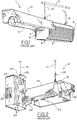
- the luminaire assembly 41 has an M-shaped reflector 43 formed from two sheets 44, 45 of thin flexible and pliant reflecting material such as sheet aluminium or sheet steel.
- the sheets 44, 45 overlap to form a spine 46 on which two lamp sockets 47, 48 are mounted each supported by corresponding brackets 147,148 which are separately formed.
- a double ended lamp 23 extends between the sockets 47, 48.
- the sheets 44, 45 can be subjected to variable tensions and thereby vary the focus of the reflector 43.
- the tension is provided by means of a pair of chains or wires 55, 56 which are schematically illustrated.
- the chains or wires 55,56 extend from opposite edges 49, 50 of the sheets 44, 45 respectively.
- the reflector 43, sockets 47, 48 and lamp 23 are all supported by a pair of U-shaped brackets 52, 53 only one of which 52 is illustrated in Fig. 3 .
- the brackets 52, 53 are directly connected to an overhead support by means of a corresponding filament 10.
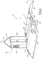
- ballast 62 has a housing 63 including heat fins 76, and a hanger 67.
- the ballast 62 is provided with a mounting mechanism which typically takes the form of mounting feet with apertures extending through the feet.
- a side plate 64 is provided and which is sized to engage with the mounting feet. That is, the ballast 62 is effectively mounted onto the side plate 64.
- Ballasts 62 having different rated power capacities will normally be of different sizes, and the side plate 64 will have a size commensurate with the intended ballast 62. For example, a 600W ballast is approximately 20-25 mm (one inch) shorter than a 1000 W ballast.
- a large side plate 64 with numerous apertures can mount a range of ballasts of different sizes.
- a reflector support arm 66 Extending from the side plate 64, and welded thereto, is a reflector support arm 66 having an orificed end plate 68 connected to its distal end.
- the reflector support arm 66 is passed through both of the U-shaped brackets 52, 53 of the luminaire 41 and the length of the arm 66 substantially corresponds to the spacing between the brackets 52, 53 so that the bracket 53 is adjacent to the side plate 64 and the bracket 52 abuts the end plate 68.
- filaments 11 and 10 are connected to the end plate 68 and the hanger 67 respectively so as to enable the close coupled luminaire assembly 61 to be suspended from an overhead support.
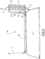
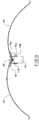
- the adjustable focus reflector 43 has a substantially rectangular form when viewed in plan, is formed from sheet metal, and has a V-shaped configuration when viewed in end elevation and in a relaxed state.
- the reflector 43 is bendable into a tensioned state having a generally M-shaped configuration when viewed in end elevation.
- a central region of the V and M shapes constitutes the spine 46.
- the ballast 62 has a female socket 58 and the lamp socket 47 has a short cable 59 extending therefrom and terminating in a male plug 57 which mates with the female socket 58.
- the short cable 59 connects the ballast 62 to the lamp 23 (not illustrated in Fig.5 ).
- the lamp sockets 47, 48 are supported by brackets 147, 148 as before.
- the brackets 147, 148 are fabricated from a single metal strip 150 which has a generally V-shaped configuration and which overlies the spine 46.
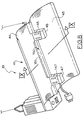
- a luminaire assembly 81 is substantially similar to that of the luminaire assembly 61 of the first embodiment.
- the electronic ballast 62, the reflector 43 and the reflector support arm 66 are the same.
- the side plate 164 is formed from a base portion 82 and a pivoted portion 83 which is connected to the base portion 82 by means of a hinge 85.
- the base portion 82 and the pivoted portion 83 can pivot relative to each other as indicated by the arrows in Fig. 7 .
- the base portion 82 is permanently connected to the reflector support arm 66, preferably by means of a weld 87.
- the hinged side plate 164 provides two very substantial advantages. The first of these is that the reflector support arm 66 and the folded side plate 164 (not connected with the ballast 62) can fit within the compact packaging used to distribute the luminaire assembly 81 (and excluding the electronic ballast 62).
- pivoted arms 83 of different lengths as indicated by dotted lines in Fig. 7 , mounting arrangements for different electronic ballasts 62 can be accommodated.
- a shorter pivoted arm 83 is available for use with a 600 W electronic ballast
- a pivoted arm 83 longer by 20-25 mm (one inch) is available for use with a 1000 W electronic ballast.
- the luminaire 41 is essentially unchanged and so the considerable capital investment in tooling up for its construction is able to be utilised to produce both the luminaire 41 which is not close coupled and the close coupled luminaire assemblies 61 and 81.
- the sheets 44, 45 can be manipulated so as to change the focus of the close coupled luminaire assembly 61 as explained in European Patent No. 1,488,167 .
- the strip 150 from which the brackets 147, 148 are fabricated is provided with two narrow, slightly upturned edges 151, 152.
- the upturned edges 151, 152 are located one to each side of the strip 150 and substantially increase the stiffness of the strip 150. Furthermore, the upturned edges 151, 152 bear against the sheets 44, 45 which make up the reflector 43. As a consequence, the reflector 43 is more stable.
- Each of the edges 151, 152 is preferably turned up through an angle of approximately 10°.
- the strip 150 with its upturned edges 151, 152 is equally applicable to the luminaire assembly of Fig. 3
- the reflector support arm 66 which is illustrated as being welded to the side plate 64, 164, which is in turn mounted on the ballast 62, can be directly connected to the ballast 62 by various different methods including direct connection with releasable engagement.
- One such method is to have a short sleeve which protrudes from the ballast 62 and into which the arm 66 can be inserted.
- the interconnection between the sleeve and the arm 66 can be either a threaded engagement or a bayonet style fitting.
- Another such method is to have the arm 66 hinged to permit it to pivot through only 90°. In this arrangement in a transport configuration, the arm 66 lies alongside the ballast 62.
- the arm swings out into the position illustrated in Fig. 4 .
- Either the sleeve arrangement or the hinged arrangement makes for a more compact package for shipping.
- the arm 66 can be telescopic, irrespective of its method of connection with the ballast 62.
- the support arm 66 can also be releasably engaged with, or detachably mounted to, the side plate 64, 164.
- This releasable engagement can be by means of a threaded sleeve, a bayonet fitting, or the like.
- the hinge 85 is not required. Since almost all ballasts are specifically designed to be mounted to a flat surface of some kind, use of the side plate 64, 164 is particularly convenient. However, it is possible to directly mount the support arm 66 to the ballast 62 without the use of any side plate by modifying, or adding to, the normal mounting arrangements for a ballast.
- the arm 66 is illustrated as being perpendicular to the longitudinal axis of the ballast 62, it is possible to mount the ballast 62 so that its longitudinal axis is parallel to, or is a prolongation of, the arm 66. This means that the ballast 62 is mounted horizontally, rather than vertically as illustrated. Stated another way, the first axis of the ballast, instead of being a longitudinal axis, is a transverse axis of the ballast.
Landscapes
- Engineering & Computer Science (AREA)
- General Engineering & Computer Science (AREA)
- Life Sciences & Earth Sciences (AREA)
- Power Engineering (AREA)
- Environmental Sciences (AREA)
- Ecology (AREA)
- Botany (AREA)
- Forests & Forestry (AREA)
- Biodiversity & Conservation Biology (AREA)
- Non-Portable Lighting Devices Or Systems Thereof (AREA)
- Securing Globes, Refractors, Reflectors Or The Like (AREA)
- Fastening Of Light Sources Or Lamp Holders (AREA)
- Aerials With Secondary Devices (AREA)
Claims (14)
- Eng gekoppelte Leuchtkörperanordnung (61), umfassend ein Vorschaltgerät (62), einen Reflektor (43) mit einem Paar voneinander beabstandeter Träger (52, 53), wobei das Vorschaltgerät (62) eine erste Achse und einen ersten Befestigungsaufsatz (67) aufweist, um zu ermöglichen, dass das Vorschaltgerät (62) durch ein erstes Filament (10) an einem Überkopfträger aufgehängt wird, wobei die erste Achse des Vorschaltgeräts im Wesentlichen vertikal ist, wobei die Anordnung (61) weiterhin einen Reflektorträgerarm (66) enthält, der mit dem Vorschaltgerät (62) verbunden ist und sich im Wesentlichen senkrecht zu der ersten Achse des Vorschaltgeräts über einen Abstand erstreckt, der mindestens so lang ist wie der Abstand zwischen den Trägern (52, 53), wobei ein distales Ende des Reflektorträgerarms (66) einen zweiten Befestigungsaufsatz (68) aufweist, um zu ermöglichen, dass das distale Ende durch ein zweites Filament (11) an einem Überkopfträger aufgehängt wird, wobei der Reflektorträgerarm (66) im Wesentlichen horizontal ist, und wobei der Reflektor (43) von dem Reflektorträgerarm (66) hängt, indem der Reflektorträgerarm (66) in die Träger (52, 53) eingreift, ohne dass eine direkte mechanische Verbindung zwischen dem Vorschaltgerät (62) und dem Reflektor (43) besteht, dadurch gekennzeichnet, dass der Reflektor (43) mindestens eine Lampenfassung (47, 48) aufweist, wobei jede Lampenfassung (47, 48) von dem Reflektor (43) getragen wird und wobei das Vorschaltgerät (62) eng von der einen Lampenfassung (47, 48) beabstandet ist.
- Anordnung (61) nach Anspruch 1, wobei der Reflektor (43) ein einstellbarer Fokusreflektor ist und in der Draufsicht eine Rechteckform umfasst, aus Blech (44, 45) gebildet ist, in der Endansicht und in einem entspannten Zustand eine V-förmige Konfiguration aufweist, und in der Endansicht in einen gespannten Zustand mit einer im Allgemeinen M-förmigen Konfiguration biegbar ist, wobei ein zentraler Bereich der V- und M-Form ein Rückgrat (46) bildet.
- Anordnung (61) nach Anspruch 2, wobei der Fokus durch Einstellen der Spannung des gespannten Zustands einstellbar ist.
- Anordnung (61) nach einem beliebigen der Ansprüche 1 bis 3, wobei der Reflektorträgerarm (66) im Wesentlichen zylindrisch ist.
- Anordnung (61) nach einem beliebigen der Ansprüche 1 bis 4, wobei der zweite Befestigungsaufsatz eine Endplatte (68) mit einer dort durchgehenden Öffnung aufweist.
- Anordnung (61) nach einem beliebigen der Ansprüche 1 bis 5, wobei der Reflektorträgerarm (66) durch eine Verbindungsplatte (64, 164), die im Wesentlichen senkrecht zu einer Längsachse des Reflektorträgerarm (66) ist, mit dem Vorschaltgerät (62) verbunden ist.
- Anordnung (61) nach Anspruch 6, wobei die Verbindungsplatte (164) in zwei Abschnitte (82, 83) unterteilt ist, die miteinander angelenkt sind.
- Anordnung (61) nach Anspruch 7, wobei der Trägerarm (66) an einem (82) der beiden Abschnitte (82, 83) befestigt ist.
- Anordnung (61) nach Anspruch 7 oder 8, wobei beide (82, 83) der beiden Abschnitte an dem Vorschaltgerät (62) befestigt sind.
- Anordnung (61) nach einem beliebigen der Ansprüche 1 bis 9, wobei die erste Achse des Vorschaltgeräts eine Längsachse des Vorschaltgeräts (62) umfasst.
- Anordnung (61) nach Anspruch 5 und einem beliebigen der Ansprüche 6 bis 10, wobei die Verbindungsplatte (64, 164) größer als die Endplatte (68) ist.
- Anordnung (61) nach einem beliebigen der Ansprüche 1 bis 11, wobei es sich bei dem Vorschaltgerät (62) um ein elektronisches Vorschaltgerät handelt.
- Verfahren zum Befestigen eines Reflektors (43) eines Leuchtkörpers, der eng an ein Vorschaltgerät (62) angrenzt, um eine eng gekoppelte Leuchtkörperanordnung (61) zu bilden, wobei der Reflektor (43) ein beabstandetes Paar von umgekehrten, im Allgemeinen U-förmigen Halterungen (52, 53) enthält und das Vorschaltgerät (62) eine erste Achse aufweist, wobei das Verfahren durch die folgenden Schritte gekennzeichnet ist:(i) Verbinden eines Reflektorträgerarms (66) mit dem Vorschaltgerät (62), so dass er im Wesentlichen senkrecht zu der ersten Achse des Vorschaltgeräts ist, wobei der Arm (66) mindestens so lang ist wie der Abstand zwischen den Halterungen (52, 53);(ii) Bereitstellen eines Befestigungsaufsatzes (68) am distalen Ende des Arms (66);(iii) Führen des Arms (66) durch beide Halterungen (52, 53), um dadurch das Vorschaltgerät (62) neben dem Reflektor (43) anzuordnen; und(iv) Tragen des Vorschaltgeräts (62) und des Befestigungsaufsatzes (68) an einem Überkopfträger, wobei der Reflektor (43) an dem Arm (66) hängt.
- Verfahren nach Anspruch 13, das den folgenden weiteren Schritt enthält:
(v) Auswählen des Reflektors (43) als ein einstellbarer Fokusreflektor (43) und Einstellen des Fokus des Reflektors (43), während der Reflektor (43) an dem Arm (66) hängt.
Applications Claiming Priority (3)
| Application Number | Priority Date | Filing Date | Title |
|---|---|---|---|
| AU2016900684A AU2016900684A0 (en) | 2016-02-25 | A Luminaire Assembly | |
| AU2016903092A AU2016903092A0 (en) | 2016-08-05 | A Luminaire Assembly | |
| PCT/AU2017/050150 WO2017143391A1 (en) | 2016-02-25 | 2017-02-21 | A luminaire assembly |
Publications (3)
| Publication Number | Publication Date |
|---|---|
| EP3420274A1 EP3420274A1 (de) | 2019-01-02 |
| EP3420274A4 EP3420274A4 (de) | 2019-11-13 |
| EP3420274B1 true EP3420274B1 (de) | 2021-06-23 |
Family
ID=59684667
Family Applications (1)
| Application Number | Title | Priority Date | Filing Date |
|---|---|---|---|
| EP17755644.6A Active EP3420274B1 (de) | 2016-02-25 | 2017-02-21 | Leuchtkörper |
Country Status (9)
| Country | Link |
|---|---|
| US (2) | US10422507B2 (de) |
| EP (1) | EP3420274B1 (de) |
| CN (1) | CN108884986B (de) |
| AU (1) | AU2017222695B2 (de) |
| CA (1) | CA3014333A1 (de) |
| CL (1) | CL2018002376A1 (de) |
| ES (1) | ES2883657T3 (de) |
| IL (1) | IL261130B (de) |
| WO (1) | WO2017143391A1 (de) |
Families Citing this family (4)
| Publication number | Priority date | Publication date | Assignee | Title |
|---|---|---|---|---|
| USD848662S1 (en) | 2017-11-03 | 2019-05-14 | Hgci, Inc. | Light reflector |
| CN109452030A (zh) * | 2018-11-30 | 2019-03-12 | 珠海美光原科技股份有限公司 | 一种补光灯及补光系统 |
| USD987158S1 (en) * | 2019-08-19 | 2023-05-23 | Chung Han Yu | LED housing |
| CN121408645A (zh) | 2020-08-12 | 2026-01-27 | Hgci股份有限公司 | 包括用于镇流器的外壳的灯具 |
Family Cites Families (18)
| Publication number | Priority date | Publication date | Assignee | Title |
|---|---|---|---|---|
| US4837669A (en) * | 1987-01-28 | 1989-06-06 | Manville Corporation | Low profile industrial luminaire |
| CA1335889C (en) * | 1988-10-07 | 1995-06-13 | Mahmoud A. Gawad | Small profile luminaire having adjustable photometric distribution |
| US5222800A (en) * | 1992-01-28 | 1993-06-29 | The Genlyte Group Incorporated | Recessed lighting fixture |
| AU679737C (en) * | 1993-11-18 | 2001-11-08 | Paul Andrew Cronk | Adjustable reflector |
| US5720546A (en) | 1994-09-20 | 1998-02-24 | The Whitaker Corp | Integrated ballast and lamp connector |
| US6152583A (en) * | 1998-02-20 | 2000-11-28 | Genlyte Thomas Group Llc | Adjustable luminaire having pivotable lamp and reflector assembly |
| US7156539B2 (en) * | 1998-03-10 | 2007-01-02 | Paul Andrew Cronk | Adjustable reflector device |
| DE19822580A1 (de) * | 1998-05-20 | 1999-12-02 | Waldmann Gmbh & Co Herbert | Leuchte mit verstellbarem Reflektor |
| GB2357332A (en) | 1999-12-15 | 2001-06-20 | John Wood | Lighting reflector comprising a plurality of contiguous portions |
| US6290375B1 (en) * | 2000-03-16 | 2001-09-18 | Cooper Technologies Company | Ballast housing having pivotally engaging mounting means |
| CN1120954C (zh) * | 2001-04-02 | 2003-09-10 | 王开富 | 远距反射式h型荧光管灯具 |
| GB0112909D0 (en) * | 2001-05-29 | 2001-07-18 | Hilclare Ltd | A luminaire |
| US6585396B1 (en) * | 2001-06-01 | 2003-07-01 | Neal R. Verfuerth | Fluorescent hanging light fixture |
| AUPS080102A0 (en) | 2002-02-27 | 2002-03-21 | Cronk, Paul Andrew | A luminaire arrangement |
| AU2003259898A1 (en) * | 2002-08-15 | 2004-03-11 | Nutech Lighting Corp., Inc. | Light fixture |
| US7952022B2 (en) * | 2009-02-16 | 2011-05-31 | Koninklijke Philips Electronics N.V. | Dual access luminaire junction box |
| US9363953B2 (en) * | 2013-09-26 | 2016-06-14 | Hydrofarm, Inc. | Ventilated grow light housing |
| US10143144B2 (en) * | 2015-06-25 | 2018-12-04 | Boulder Lamp, Inc. | Daisy chain grow light |
-
2017
- 2017-02-21 EP EP17755644.6A patent/EP3420274B1/de active Active
- 2017-02-21 ES ES17755644T patent/ES2883657T3/es active Active
- 2017-02-21 AU AU2017222695A patent/AU2017222695B2/en not_active Ceased
- 2017-02-21 US US16/079,282 patent/US10422507B2/en not_active Expired - Fee Related
- 2017-02-21 CN CN201780013387.6A patent/CN108884986B/zh not_active Expired - Fee Related
- 2017-02-21 CA CA3014333A patent/CA3014333A1/en not_active Abandoned
- 2017-02-21 WO PCT/AU2017/050150 patent/WO2017143391A1/en not_active Ceased
-
2018
- 2018-08-13 IL IL261130A patent/IL261130B/en active IP Right Grant
- 2018-08-18 CL CL2018002376A patent/CL2018002376A1/es unknown
-
2019
- 2019-08-12 US US16/537,792 patent/US10775020B2/en not_active Expired - Fee Related
Non-Patent Citations (1)
| Title |
|---|
| None * |
Also Published As
| Publication number | Publication date |
|---|---|
| EP3420274A4 (de) | 2019-11-13 |
| US10422507B2 (en) | 2019-09-24 |
| IL261130A (en) | 2018-10-31 |
| US10775020B2 (en) | 2020-09-15 |
| US20190360660A1 (en) | 2019-11-28 |
| CN108884986B (zh) | 2020-12-18 |
| CL2018002376A1 (es) | 2019-02-01 |
| WO2017143391A9 (en) | 2017-10-19 |
| AU2017222695A1 (en) | 2018-09-27 |
| CN108884986A (zh) | 2018-11-23 |
| IL261130B (en) | 2021-06-30 |
| WO2017143391A1 (en) | 2017-08-31 |
| US20190049095A1 (en) | 2019-02-14 |
| AU2017222695B2 (en) | 2021-03-25 |
| CA3014333A1 (en) | 2017-08-31 |
| EP3420274A1 (de) | 2019-01-02 |
| ES2883657T3 (es) | 2021-12-09 |
Similar Documents
| Publication | Publication Date | Title |
|---|---|---|
| US10775020B2 (en) | Luminaire assembly | |
| US11085617B2 (en) | Foldable LED lamp with detachable ballast and use method thereof | |
| CA2881619C (en) | Opto-mechanically adjustable and expandable light fixtures | |
| US6494601B2 (en) | Modular cluster lighting fixture | |
| CA2276884C (en) | Suspended luminaire assembly | |
| US20130343048A1 (en) | Light reflector for a horticultural device | |
| EP2620053B1 (de) | Forstwirtschaftliche Beleuchtung | |
| CN206234692U (zh) | 一种手术反光灯 | |
| JP4051809B2 (ja) | 照明器具 | |
| KR100419399B1 (ko) | 형광등기구 | |
| CN208620153U (zh) | 一种线性工矿灯 | |
| KR200185886Y1 (ko) | 걸이형 조명등 | |
| KR20150002572U (ko) | 휴대용 조명장치 | |
| CN214628327U (zh) | 一种灯具 | |
| AU2015311607B2 (en) | Luminaire and luminaire components | |
| CN215683555U (zh) | 一种led植物生长灯 | |
| US7517104B1 (en) | Mogul based bench worklight | |
| KR101307702B1 (ko) | 조명등용 교체용 내부반사갓 | |
| CN210050661U (zh) | 一种松果投光灯 | |
| JP2009045061A (ja) | 漁船用集魚灯装置 | |
| EP3434970B1 (de) | Beleuchtungseinrichtung für gerichtete beleuchtung | |
| CN204100168U (zh) | 可调式天花灯安装系统 | |
| CN204951179U (zh) | 一种多功能外科手术用挂钩架 | |
| CN109163242A (zh) | 一种便于安装及调节的挂灯 | |
| WO2004020897A1 (en) | Luminaire |
Legal Events
| Date | Code | Title | Description |
|---|---|---|---|
| STAA | Information on the status of an ep patent application or granted ep patent |
Free format text: STATUS: THE INTERNATIONAL PUBLICATION HAS BEEN MADE |
|
| PUAI | Public reference made under article 153(3) epc to a published international application that has entered the european phase |
Free format text: ORIGINAL CODE: 0009012 |
|
| STAA | Information on the status of an ep patent application or granted ep patent |
Free format text: STATUS: REQUEST FOR EXAMINATION WAS MADE |
|
| 17P | Request for examination filed |
Effective date: 20180911 |
|
| AK | Designated contracting states |
Kind code of ref document: A1 Designated state(s): AL AT BE BG CH CY CZ DE DK EE ES FI FR GB GR HR HU IE IS IT LI LT LU LV MC MK MT NL NO PL PT RO RS SE SI SK SM TR |
|
| AX | Request for extension of the european patent |
Extension state: BA ME |
|
| DAV | Request for validation of the european patent (deleted) | ||
| DAX | Request for extension of the european patent (deleted) | ||
| A4 | Supplementary search report drawn up and despatched |
Effective date: 20191011 |
|
| RIC1 | Information provided on ipc code assigned before grant |
Ipc: F21V 17/10 20060101ALI20191007BHEP Ipc: F21S 8/06 20060101ALI20191007BHEP Ipc: F21V 23/02 20060101ALI20191007BHEP Ipc: F21V 7/24 20180101ALN20191007BHEP Ipc: F21V 7/16 20060101ALN20191007BHEP Ipc: F21V 7/00 20060101ALI20191007BHEP Ipc: A01G 7/04 20060101AFI20191007BHEP Ipc: F21V 17/08 20060101ALI20191007BHEP Ipc: F21Y 103/00 20160101ALN20191007BHEP |
|
| STAA | Information on the status of an ep patent application or granted ep patent |
Free format text: STATUS: EXAMINATION IS IN PROGRESS |
|
| 17Q | First examination report despatched |
Effective date: 20200812 |
|
| REG | Reference to a national code |
Ref country code: DE Ref legal event code: R079 Ref document number: 602017040818 Country of ref document: DE Free format text: PREVIOUS MAIN CLASS: F21V0023000000 Ipc: A01G0007040000 |
|
| RIC1 | Information provided on ipc code assigned before grant |
Ipc: A01G 7/04 20060101AFI20201215BHEP Ipc: F21V 17/08 20060101ALI20201215BHEP Ipc: F21S 8/06 20060101ALI20201215BHEP Ipc: F21V 7/24 20180101ALN20201215BHEP Ipc: F21V 7/16 20060101ALN20201215BHEP Ipc: F21V 7/00 20060101ALI20201215BHEP Ipc: F21V 23/02 20060101ALI20201215BHEP Ipc: F21Y 103/00 20160101ALN20201215BHEP Ipc: F21V 17/10 20060101ALI20201215BHEP |
|
| GRAP | Despatch of communication of intention to grant a patent |
Free format text: ORIGINAL CODE: EPIDOSNIGR1 |
|
| STAA | Information on the status of an ep patent application or granted ep patent |
Free format text: STATUS: GRANT OF PATENT IS INTENDED |
|
| INTG | Intention to grant announced |
Effective date: 20210211 |
|
| GRAS | Grant fee paid |
Free format text: ORIGINAL CODE: EPIDOSNIGR3 |
|
| GRAA | (expected) grant |
Free format text: ORIGINAL CODE: 0009210 |
|
| STAA | Information on the status of an ep patent application or granted ep patent |
Free format text: STATUS: THE PATENT HAS BEEN GRANTED |
|
| AK | Designated contracting states |
Kind code of ref document: B1 Designated state(s): AL AT BE BG CH CY CZ DE DK EE ES FI FR GB GR HR HU IE IS IT LI LT LU LV MC MK MT NL NO PL PT RO RS SE SI SK SM TR |
|
| REG | Reference to a national code |
Ref country code: GB Ref legal event code: FG4D |
|
| REG | Reference to a national code |
Ref country code: CH Ref legal event code: EP |
|
| REG | Reference to a national code |
Ref country code: DE Ref legal event code: R096 Ref document number: 602017040818 Country of ref document: DE Ref country code: AT Ref legal event code: REF Ref document number: 1403452 Country of ref document: AT Kind code of ref document: T Effective date: 20210715 |
|
| REG | Reference to a national code |
Ref country code: IE Ref legal event code: FG4D |
|
| REG | Reference to a national code |
Ref country code: NL Ref legal event code: FP |
|
| REG | Reference to a national code |
Ref country code: LT Ref legal event code: MG9D |
|
| PG25 | Lapsed in a contracting state [announced via postgrant information from national office to epo] |
Ref country code: FI Free format text: LAPSE BECAUSE OF FAILURE TO SUBMIT A TRANSLATION OF THE DESCRIPTION OR TO PAY THE FEE WITHIN THE PRESCRIBED TIME-LIMIT Effective date: 20210623 Ref country code: LT Free format text: LAPSE BECAUSE OF FAILURE TO SUBMIT A TRANSLATION OF THE DESCRIPTION OR TO PAY THE FEE WITHIN THE PRESCRIBED TIME-LIMIT Effective date: 20210623 Ref country code: HR Free format text: LAPSE BECAUSE OF FAILURE TO SUBMIT A TRANSLATION OF THE DESCRIPTION OR TO PAY THE FEE WITHIN THE PRESCRIBED TIME-LIMIT Effective date: 20210623 Ref country code: BG Free format text: LAPSE BECAUSE OF FAILURE TO SUBMIT A TRANSLATION OF THE DESCRIPTION OR TO PAY THE FEE WITHIN THE PRESCRIBED TIME-LIMIT Effective date: 20210923 |
|
| PG25 | Lapsed in a contracting state [announced via postgrant information from national office to epo] |
Ref country code: SE Free format text: LAPSE BECAUSE OF FAILURE TO SUBMIT A TRANSLATION OF THE DESCRIPTION OR TO PAY THE FEE WITHIN THE PRESCRIBED TIME-LIMIT Effective date: 20210623 Ref country code: RS Free format text: LAPSE BECAUSE OF FAILURE TO SUBMIT A TRANSLATION OF THE DESCRIPTION OR TO PAY THE FEE WITHIN THE PRESCRIBED TIME-LIMIT Effective date: 20210623 Ref country code: LV Free format text: LAPSE BECAUSE OF FAILURE TO SUBMIT A TRANSLATION OF THE DESCRIPTION OR TO PAY THE FEE WITHIN THE PRESCRIBED TIME-LIMIT Effective date: 20210623 Ref country code: NO Free format text: LAPSE BECAUSE OF FAILURE TO SUBMIT A TRANSLATION OF THE DESCRIPTION OR TO PAY THE FEE WITHIN THE PRESCRIBED TIME-LIMIT Effective date: 20210923 Ref country code: GR Free format text: LAPSE BECAUSE OF FAILURE TO SUBMIT A TRANSLATION OF THE DESCRIPTION OR TO PAY THE FEE WITHIN THE PRESCRIBED TIME-LIMIT Effective date: 20210924 |
|
| REG | Reference to a national code |
Ref country code: ES Ref legal event code: FG2A Ref document number: 2883657 Country of ref document: ES Kind code of ref document: T3 Effective date: 20211209 |
|
| PG25 | Lapsed in a contracting state [announced via postgrant information from national office to epo] |
Ref country code: EE Free format text: LAPSE BECAUSE OF FAILURE TO SUBMIT A TRANSLATION OF THE DESCRIPTION OR TO PAY THE FEE WITHIN THE PRESCRIBED TIME-LIMIT Effective date: 20210623 Ref country code: RO Free format text: LAPSE BECAUSE OF FAILURE TO SUBMIT A TRANSLATION OF THE DESCRIPTION OR TO PAY THE FEE WITHIN THE PRESCRIBED TIME-LIMIT Effective date: 20210623 Ref country code: PT Free format text: LAPSE BECAUSE OF FAILURE TO SUBMIT A TRANSLATION OF THE DESCRIPTION OR TO PAY THE FEE WITHIN THE PRESCRIBED TIME-LIMIT Effective date: 20211025 Ref country code: SM Free format text: LAPSE BECAUSE OF FAILURE TO SUBMIT A TRANSLATION OF THE DESCRIPTION OR TO PAY THE FEE WITHIN THE PRESCRIBED TIME-LIMIT Effective date: 20210623 Ref country code: SK Free format text: LAPSE BECAUSE OF FAILURE TO SUBMIT A TRANSLATION OF THE DESCRIPTION OR TO PAY THE FEE WITHIN THE PRESCRIBED TIME-LIMIT Effective date: 20210623 |
|
| PG25 | Lapsed in a contracting state [announced via postgrant information from national office to epo] |
Ref country code: PL Free format text: LAPSE BECAUSE OF FAILURE TO SUBMIT A TRANSLATION OF THE DESCRIPTION OR TO PAY THE FEE WITHIN THE PRESCRIBED TIME-LIMIT Effective date: 20210623 |
|
| REG | Reference to a national code |
Ref country code: AT Ref legal event code: UEP Ref document number: 1403452 Country of ref document: AT Kind code of ref document: T Effective date: 20210623 |
|
| REG | Reference to a national code |
Ref country code: DE Ref legal event code: R097 Ref document number: 602017040818 Country of ref document: DE |
|
| PG25 | Lapsed in a contracting state [announced via postgrant information from national office to epo] |
Ref country code: DK Free format text: LAPSE BECAUSE OF FAILURE TO SUBMIT A TRANSLATION OF THE DESCRIPTION OR TO PAY THE FEE WITHIN THE PRESCRIBED TIME-LIMIT Effective date: 20210623 |
|
| PLBE | No opposition filed within time limit |
Free format text: ORIGINAL CODE: 0009261 |
|
| STAA | Information on the status of an ep patent application or granted ep patent |
Free format text: STATUS: NO OPPOSITION FILED WITHIN TIME LIMIT |
|
| 26N | No opposition filed |
Effective date: 20220324 |
|
| PG25 | Lapsed in a contracting state [announced via postgrant information from national office to epo] |
Ref country code: AL Free format text: LAPSE BECAUSE OF FAILURE TO SUBMIT A TRANSLATION OF THE DESCRIPTION OR TO PAY THE FEE WITHIN THE PRESCRIBED TIME-LIMIT Effective date: 20210623 |
|
| REG | Reference to a national code |
Ref country code: DE Ref legal event code: R119 Ref document number: 602017040818 Country of ref document: DE |
|
| PG25 | Lapsed in a contracting state [announced via postgrant information from national office to epo] |
Ref country code: MC Free format text: LAPSE BECAUSE OF FAILURE TO SUBMIT A TRANSLATION OF THE DESCRIPTION OR TO PAY THE FEE WITHIN THE PRESCRIBED TIME-LIMIT Effective date: 20210623 |
|
| REG | Reference to a national code |
Ref country code: NL Ref legal event code: MM Effective date: 20220301 |
|
| REG | Reference to a national code |
Ref country code: CH Ref legal event code: PL |
|
| REG | Reference to a national code |
Ref country code: BE Ref legal event code: MM Effective date: 20220228 |
|
| GBPC | Gb: european patent ceased through non-payment of renewal fee |
Effective date: 20220221 |
|
| PG25 | Lapsed in a contracting state [announced via postgrant information from national office to epo] |
Ref country code: LU Free format text: LAPSE BECAUSE OF NON-PAYMENT OF DUE FEES Effective date: 20220221 Ref country code: CZ Free format text: LAPSE BECAUSE OF NON-PAYMENT OF DUE FEES Effective date: 20220221 |
|
| PG25 | Lapsed in a contracting state [announced via postgrant information from national office to epo] |
Ref country code: NL Free format text: LAPSE BECAUSE OF NON-PAYMENT OF DUE FEES Effective date: 20220301 Ref country code: FR Free format text: LAPSE BECAUSE OF NON-PAYMENT OF DUE FEES Effective date: 20220228 |
|
| PG25 | Lapsed in a contracting state [announced via postgrant information from national office to epo] |
Ref country code: LI Free format text: LAPSE BECAUSE OF NON-PAYMENT OF DUE FEES Effective date: 20220228 Ref country code: IE Free format text: LAPSE BECAUSE OF NON-PAYMENT OF DUE FEES Effective date: 20220221 Ref country code: GB Free format text: LAPSE BECAUSE OF NON-PAYMENT OF DUE FEES Effective date: 20220221 Ref country code: DE Free format text: LAPSE BECAUSE OF NON-PAYMENT OF DUE FEES Effective date: 20220901 Ref country code: CH Free format text: LAPSE BECAUSE OF NON-PAYMENT OF DUE FEES Effective date: 20220228 |
|
| PG25 | Lapsed in a contracting state [announced via postgrant information from national office to epo] |
Ref country code: BE Free format text: LAPSE BECAUSE OF NON-PAYMENT OF DUE FEES Effective date: 20220228 |
|
| REG | Reference to a national code |
Ref country code: ES Ref legal event code: FD2A Effective date: 20230331 |
|
| REG | Reference to a national code |
Ref country code: AT Ref legal event code: MM01 Ref document number: 1403452 Country of ref document: AT Kind code of ref document: T Effective date: 20220221 |
|
| PG25 | Lapsed in a contracting state [announced via postgrant information from national office to epo] |
Ref country code: ES Free format text: LAPSE BECAUSE OF NON-PAYMENT OF DUE FEES Effective date: 20220222 Ref country code: AT Free format text: LAPSE BECAUSE OF NON-PAYMENT OF DUE FEES Effective date: 20220221 |
|
| PG25 | Lapsed in a contracting state [announced via postgrant information from national office to epo] |
Ref country code: IT Free format text: LAPSE BECAUSE OF NON-PAYMENT OF DUE FEES Effective date: 20220221 |
|
| PG25 | Lapsed in a contracting state [announced via postgrant information from national office to epo] |
Ref country code: HU Free format text: LAPSE BECAUSE OF FAILURE TO SUBMIT A TRANSLATION OF THE DESCRIPTION OR TO PAY THE FEE WITHIN THE PRESCRIBED TIME-LIMIT; INVALID AB INITIO Effective date: 20170221 |
|
| PG25 | Lapsed in a contracting state [announced via postgrant information from national office to epo] |
Ref country code: MK Free format text: LAPSE BECAUSE OF FAILURE TO SUBMIT A TRANSLATION OF THE DESCRIPTION OR TO PAY THE FEE WITHIN THE PRESCRIBED TIME-LIMIT Effective date: 20210623 Ref country code: CY Free format text: LAPSE BECAUSE OF FAILURE TO SUBMIT A TRANSLATION OF THE DESCRIPTION OR TO PAY THE FEE WITHIN THE PRESCRIBED TIME-LIMIT Effective date: 20210623 |
|
| PG25 | Lapsed in a contracting state [announced via postgrant information from national office to epo] |
Ref country code: MT Free format text: LAPSE BECAUSE OF FAILURE TO SUBMIT A TRANSLATION OF THE DESCRIPTION OR TO PAY THE FEE WITHIN THE PRESCRIBED TIME-LIMIT Effective date: 20210623 |
|
| PG25 | Lapsed in a contracting state [announced via postgrant information from national office to epo] |
Ref country code: TR Free format text: LAPSE BECAUSE OF FAILURE TO SUBMIT A TRANSLATION OF THE DESCRIPTION OR TO PAY THE FEE WITHIN THE PRESCRIBED TIME-LIMIT Effective date: 20210623 |