EP3420155B1 - A mounting bracket for installation of a window in a roof structure - Google Patents
A mounting bracket for installation of a window in a roof structure Download PDFInfo
- Publication number
- EP3420155B1 EP3420155B1 EP17708424.1A EP17708424A EP3420155B1 EP 3420155 B1 EP3420155 B1 EP 3420155B1 EP 17708424 A EP17708424 A EP 17708424A EP 3420155 B1 EP3420155 B1 EP 3420155B1
- Authority
- EP
- European Patent Office
- Prior art keywords
- bracket
- mounting bracket
- flange
- leg
- window
- Prior art date
- Legal status (The legal status is an assumption and is not a legal conclusion. Google has not performed a legal analysis and makes no representation as to the accuracy of the status listed.)
- Active
Links
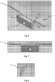
Images



Classifications
-
- E—FIXED CONSTRUCTIONS
- E04—BUILDING
- E04D—ROOF COVERINGS; SKY-LIGHTS; GUTTERS; ROOF-WORKING TOOLS
- E04D13/00—Special arrangements or devices in connection with roof coverings; Protection against birds; Roof drainage ; Sky-lights
- E04D13/03—Sky-lights; Domes; Ventilating sky-lights
- E04D13/0305—Supports or connecting means for sky-lights of flat or domed shape
- E04D13/031—Supports or connecting means for sky-lights of flat or domed shape characterised by a frame for connection to an inclined roof
-
- E—FIXED CONSTRUCTIONS
- E04—BUILDING
- E04D—ROOF COVERINGS; SKY-LIGHTS; GUTTERS; ROOF-WORKING TOOLS
- E04D13/00—Special arrangements or devices in connection with roof coverings; Protection against birds; Roof drainage ; Sky-lights
- E04D13/03—Sky-lights; Domes; Ventilating sky-lights
-
- E—FIXED CONSTRUCTIONS
- E06—DOORS, WINDOWS, SHUTTERS, OR ROLLER BLINDS IN GENERAL; LADDERS
- E06B—FIXED OR MOVABLE CLOSURES FOR OPENINGS IN BUILDINGS, VEHICLES, FENCES OR LIKE ENCLOSURES IN GENERAL, e.g. DOORS, WINDOWS, BLINDS, GATES
- E06B1/00—Border constructions of openings in walls, floors, or ceilings; Frames to be rigidly mounted in such openings
- E06B1/56—Fastening frames to the border of openings or to similar contiguous frames
- E06B1/60—Fastening frames to the border of openings or to similar contiguous frames by mechanical means, e.g. anchoring means
Definitions
- the present invention relates to a mounting bracket adapted for installation of a window in a roof structure, said window comprising a frame including a top frame member, a bottom frame member and two side frame members, the mounting bracket comprising a first bracket leg for fastening to the roof structure, and, for fastening to a frame member, a second bracket leg extending from the first bracket leg at an angle, the angle being essentially orthogonal in an unloaded condition of the mounting bracket.
- the invention furthermore relates to a window for installation in a roof structure provided with a plurality of such mounting brackets.
- unloaded condition in this context means that the mounting bracket experiences only the inherent loads coming from holding the window in place in the roof structure. No externally induced loads, such as loads coming from wind or snow acts on the bracket in the unloaded condition.
- a mounting bracket of the above-described kind is for instance known from WO 2010/009727 A1 .
- the mounting bracket has been made amply stiff so as to be able to hold the window in place even under severe circumstances, such as tough weather.
- the first load situation in which forces act on the mounting bracket so as to diminish the angle, corresponds for instance to a situation of a wind load acting on the window, the wind pulling in the window in a direction out of the roof structure.
- the second load situation in which forces act on the mounting bracket so as to increase the angle, corresponds for instance to a situation of a snow load acting on the window, the snow pressing on the window in a direction into the roof structure. Due to the provision of different properties in the two directions, the combination of features aimed at is achieved, and it is possible to design the mounting bracket to have sufficient stiffness to be able to resist for instance snow loads without experiencing plastic deformation. However, when subjected to more severe loads, such as an impact, the second torque threshold will be exceeded and the mounting bracket will yield. The plastic deformation that the mounting bracket experiences in this situation will absorb a major part of the energy from the impact. Thereby less strain is put on the remaining window structure.
- the fact that the mounting bracket itself yields provides for a simple solution keeping the number of parts needed for mounting the window low. It also provides for a compact design.
- the fact that the plastic deformation of the mounting bracket alters the angle between the two bracket legs essentially without any deformation of for instance the holes provided in the mounting bracket for fastening the mounting bracket to the window and roof structure provides for a continuously secure and relatively well-defined fastening of the window to the surrounding roof structure even after an impact load.
- Fig. 1A shows a window 1 adapted to be installed in a roof structure (not shown).
- the window 1 comprises a frame including a top frame member 2, a bottom frame member 3 and two side frame members 4, 5.
- the window 1 is mounted in the roof structure by means of a number of mounting brackets as will be described in the following.
- the window 1 also comprises a sash 1a hingedly connected to the window frame.
- the general structure of the window 1 including parts of the sash 1a are known per se and will not be described in further detail.
- a plurality of mounting brackets For mounting the window 1 in the roof structure, a plurality of mounting brackets is provided.
- a prior art mounting bracket 6' mounted at the lower right-hand corner of the side frame member 4 of the window of Fig. 1A represents said plurality of mounting brackets.
- the number of mounting brackets necessary for mounting the window may depend on the window size etc, but usually a plurality of four to eight mounting brackets is used.
- the installation level in the mounted position provided in Fig. 1B is an alternative to the standard installation level in the mounted position shown in Fig. 1C .
- the mounting bracket 6' In the mounted position shown in Fig. 1C , the mounting bracket 6' is mounted on bottom frame member 3 of the window of Fig. 1A , to provide another installation level of the window 1 in relation to the surrounding building structure.
- Markings on the window frame are associated with respective grooves for use with the plurality of mounting brackets in a desired level. Details regarding the mounting bracket 6' and the installation thereof are described in Applicant's European patent application with the publication No. 2578763A1 .
- FIG. 2 shows a mounting bracket 6 according to a first version in closer detail, said version not being part of the claimed invention. Reference is also made to Figs 3 to 5 , showing further views of the mounting bracket 6 in the first version.
- Fig. 2 an orthogonal co-ordinate system x-y-z is shown for clarity reasons only.
- the components of the mounting bracket 6 may be defined by any other system of orientation.
- the mounting bracket 6 comprises a first bracket leg 7 for fastening to the roof structure, and a second bracket leg 8 for fastening to a frame member 2, 3, 4 or 5 of the window 1.
- the second bracket leg 8 extends from the first bracket leg 7 at an angle ⁇ in the embodiment shown. It is also conceivable that the first and second bracket legs 7, 8 are not adjoining but that an intermediate element or section is present.
- the mounting bracket is in Figs 2 to 5 shown in an unloaded condition, and as is seen, the angle ⁇ is essentially 90° in the unloaded condition of the mounting bracket 6. Referring to the co-ordinate system, the first bracket leg 7 extends essentially in the xy plane and the second bracket leg 8 essentially in the yz plane in the embodiment shown.
- two flanges 9 extend at an angle ⁇ from the second bracket leg 8, so that an edge 10 of the flange 9 faces the first bracket leg 7.
- a gap 19 is present between the edge 10 and the first bracket leg 7.
- the edge 10 is proximal to the first bracket leg 7 in the unloaded condition such that the gap 19 between the edge 10 and the first bracket leg 7 is approximately 0.2 mm across the whole length of the flange edge 10.
- proximal envisages gaps in the order 0.1 to 0.3 mm. Also skewed gaps presenting a varying distance between the flange edge and opposing bracket leg are conceivable. However, it is also conceivable that the edge 10 of the flange 9 is located adjacent to the first bracket leg 7, i.e. no gap present.
- the angle ⁇ between flange 9 and the bracket leg 8, from which the flange 9 extends is essentially 90°. That is, the angle ⁇ is the angle measured in the xy plane in the co-ordinate system.
- other values for the angle ⁇ are conceivable, preferably in the range of 45° to 135°, probably more preferred 70-110°, most preferred 80°-100°, in order to provide for a sufficiently robust design of the flanges acting as stiffening ribs.
- the opposing bracket leg should extend further than is the case of the first version of Figs 2 to 5 so as to be able to be abutted by the flange edge in that position of the flange.
- angle ⁇ between the flange 9 and the opposing bracket leg 7 is essentially orthogonal in the embodiment shown.
- angle ⁇ is the angle measured in the yz plane. It is noted that both of the angles ⁇ and ⁇ are orthogonal in the version of the mounting bracket shown in Figs 2 to 8 in order to obtain a robust construction. However, combinations of various sizes of angles for both ⁇ and ⁇ are conceivable.
- Embodiments comprising just one flange or more than two flanges are also conceivable; however, embodiments with an essentially symmetric arrangement of more than one flange around a symmetry plane C are preferred in order to ensure a uniform deformation, as will be further described below.
- the flanges 9 in the first version are integrally formed with the second bracket leg 8.
- the integrally formed flanges 9 have been obtained by bending and extend from each end 18 of the second bracket leg 8.
- Embodiments with flanges that are not integrally formed with the mounting bracket leg, from which they extend, or combinations of integrally and not integrally formed flanges, are conceivable.
- Non-integral flanges could for instance be added, for instance welded or bolted, onto the respective mounting bracket leg.
- a mounting bracket with three or four flanges may for instance comprise an integrally formed, bent flange at each end of the second bracket leg and one or more flanges added onto the second bracket.
- the flanges 9 of the first version are substantially triangular with a straight free edge 20. This is beneficial with regard to maximizing the stiffness of the flanges 9 acting as stiffening ribs in the first load condition, while minimizing the overall weight of the mounting bracket. Nevertheless, other shapes of flanges are conceivable, for instance rectangular or flanges with a convexly or concavely curved free edge.
- Fig. 4 the forces acting on the window 1 in various load conditions will be described.
- the first bracket leg 7 is fixed to the roof structure and a frame member of the window 1 is fastened to the second bracket leg 8.
- Forces F1 and F2 acting on the window 1 are transferred to the mounting bracket 6 as will be described in the following:
- forces F1 act on the window 1 and are transferred to the mounting bracket 6 so as to diminish the angle ⁇ .
- the mounting bracket 6 of the first version deforms elastically.
- the gap 19 is minimized, if not already closed, as the edge 10 of the flange 9 is brought into abutment with the other bracket leg 7 than the one 8 it extends from.
- the flanges 9 acting as stiffening ribs in the first load situation provide for a first torque threshold T1 in the first version.
- the mounting bracket is so designed as to be able to withstand even severe yet commonly occurring loads in this situation, such as wind loads acting on the window.
- the mounting bracket 6 is so designed as to be able to withstand even severe yet commonly occurring loads in this situation, such as snow loads acting on the window, without exceeding the second torque threshold T2, i.e. only deforming elastically. However, when subjected to larger loads, such as an impact, the second torque threshold T2 will be exceeded and the mounting bracket 6 will deform plastically thereby absorbing energy from the impact protecting other parts of the window and surrounding structure.
- the second torque threshold T2 is smaller than the first torque threshold T1, but embodiments where the opposite is the case might be envisaged.
- the first deformation zone 11 is essentially line-shaped and extends along a line 15.
- the line 15 is essentially parallel to the longitudinal extension of the interconnection 13 of the first bracket leg 7 with the second bracket leg 8.
- the line 15 is also offset from the interconnection 13 so as to intersect a point of contact 14 between the first bracket leg 7 and the flange edge 10.
- the point of contact 14 is essentially the point of contact farthest away from the interconnection 13, since this will be the natural bending point in the first load situation.
- Variations in the flange design providing for variations in the shape of the first deformation zone may be envisaged.
- a rounded tip of the flange where the free flange edge and the abutment flange edge meet may provide for a broader, more strip-shaped, first deformation zone.
- deformation of the mounting bracket 6 occurs primarily in a second deformation zone 12 in the first bracket leg 7.
- the second deformation zone 12 is delimited by the interconnection 13 and the line 15 and is marked by a darker colour in Fig. 3 .
- deformation will occur in whole or parts of the second deformation zone 12 depending on the specific design of the area.
- the mounting bracket 6 of the first version has a weakening geometry in the second deformation zone 12.
- the weakening geometry is in the form of a slit 16 but could also take other forms.
- the slit is, in the embodiment shown, essentially centrally placed in the second deformation zone 12 and extending with its longitudinal extension essentially parallel to the interconnection 13 and with equal distance to the line 15 and the interconnection 13. The particular position and orientation of the slit may vary.
- the dimensions of the slit 16 may be varied according to specifications and legislative regulations and furthermore taking into account climate conditions including the risk of extreme weather.
- the slit 16 extends across approximately 70-90 percent of the width wd2 of the second deformation zone 12 and across approximately 5-15 percent of the height hd2 of the second deformation zone 12. This arrangement provides for areas in the second deformation zone indicated in Fig. 5 , which areas will undergo the most plastic deformation.
- the first bracket leg 7 is essentially T-shaped in that the width of the first bracket leg 7 at the second deformation zone 12 is essentially identical to the width wd2 of the second deformation zone 12, while the width wl1 of the remainder of the first bracket leg 7 is larger than the width wd2 of the second deformation zone.
- the relationship between the narrower and the wider part of the first bracket leg is around 0.45, but may vary between 0.40-0.50 or even 0.30-0.60 so as to fit well to various sizes and types of windows and roof structures.
- the overall height hl1 of the first bracket leg is essentially 1.5-3 times the height hd2 of the second deformation zone 12, but may also vary so as to fit to various sizes and types of windows and roof structures.
- the width wl2 of the second bracket leg 8 is essentially equal to the width wd2 of the second deformation zone 12 but may also vary.
- the first torque threshold T1 and the second torque threshold are different from each other.
- the first torque threshold T1 is substantially larger than the second torque threshold T2.
- Typical ratios T1:T2 are 1.5 to 5, but depending on the window, expected loads and use, however, other ratios are envisaged.
- Figs 6 to 8 the configuration of the mounting bracket 6 of the first version following an impact is shown.
- the mounting bracket 6 has undergone plastic deformation in the deformation zones described in the above.
- the first bracket leg 7 has been twisted and slightly bent, the slit 16 has been stretched, and the gap 19 between the edge 10 and the first leg 7 has widened.
- FIGs 9 and 10 an embodiment of the mounting bracket according to the invention will be described. Elements and parts having the same or analogous function as in the first version of Figs 2 to 8 carry the same reference numerals to which 100 has been added. Only differences relative to the first version will be described.
- flanges 109 are angled slightly outwards and form another angle (corresponding to angle ⁇ described with reference to Fig. 2 ) than orthogonal with the second bracket leg 108.
- edge 110 has an extension providing a point of contact 114 between the edge 110 and the first bracket leg 107.
- the configuration of the mounting bracket 106 in this embodiment furthermore includes a profiling of the edge of in particular the first bracket leg 107 which enables accommodation of a corresponding mounting bracket installed on an adjacent window.
- a plurality of the mounting brackets 106 is provided separately from the window, for instance the window 1 of Fig. 1 , in a supply condition.
- the mounting brackets 106 of the plurality provided with the window 1 in the supply condition may as shown in Fig. 10 include four mounting brackets 106.
- these mounting brackets 106 are stacked on each other in a stacking unit 150 which is able to accommodate all four mounting brackets 106, and if necessary several more mounting brackets.
- the stacking unit 150 includes a set of protruding fingers 151 introduced through the respective slits 116 of the mounting brackets 106.
Landscapes
- Engineering & Computer Science (AREA)
- Civil Engineering (AREA)
- Structural Engineering (AREA)
- Architecture (AREA)
- Mechanical Engineering (AREA)
- Connection Of Plates (AREA)
Description
- The present invention relates to a mounting bracket adapted for installation of a window in a roof structure, said window comprising a frame including a top frame member, a bottom frame member and two side frame members, the mounting bracket comprising a first bracket leg for fastening to the roof structure, and, for fastening to a frame member, a second bracket leg extending from the first bracket leg at an angle, the angle being essentially orthogonal in an unloaded condition of the mounting bracket. The invention furthermore relates to a window for installation in a roof structure provided with a plurality of such mounting brackets.
- The term "unloaded condition" in this context means that the mounting bracket experiences only the inherent loads coming from holding the window in place in the roof structure. No externally induced loads, such as loads coming from wind or snow acts on the bracket in the unloaded condition.
- A mounting bracket of the above-described kind is for instance known from
WO 2010/009727 A1 . The mounting bracket has been made amply stiff so as to be able to hold the window in place even under severe circumstances, such as tough weather. - One downside is, however, that when the window is subjected to for instance an impact, the mounting brackets hold, but other parts of the window break.
- Improving the properties as regards impacts or other sudden changes of the load conditions, has been addressed in the prior art, including the ones described and shown in published applications Nos
EP1361331A2 ,US 2008/086960 A1 andKR20120089053A -
US 6 213 679 discloses another mounting bracket. - Although the above-mentioned suggested solutions provide for some absorption of forces during certain load conditions, there is still room for improvement.
- With this background, it is an object of the present invention to provide a mounting bracket of the kind mentioned in the introduction and which provides for improved impact-resistant properties.
- This and further objects are achieved by a mounting bracket according to
claim 1. - The first load situation, in which forces act on the mounting bracket so as to diminish the angle, corresponds for instance to a situation of a wind load acting on the window, the wind pulling in the window in a direction out of the roof structure. The second load situation, in which forces act on the mounting bracket so as to increase the angle, corresponds for instance to a situation of a snow load acting on the window, the snow pressing on the window in a direction into the roof structure. Due to the provision of different properties in the two directions, the combination of features aimed at is achieved, and it is possible to design the mounting bracket to have sufficient stiffness to be able to resist for instance snow loads without experiencing plastic deformation. However, when subjected to more severe loads, such as an impact, the second torque threshold will be exceeded and the mounting bracket will yield. The plastic deformation that the mounting bracket experiences in this situation will absorb a major part of the energy from the impact. Thereby less strain is put on the remaining window structure.
- Thereby is obtained a mounting bracket that holds when subjected to severe weather conditions, but yields when subjected to even larger loads, such as impacts.
- The fact that the mounting bracket itself yields provides for a simple solution keeping the number of parts needed for mounting the window low. It also provides for a compact design. The fact that the plastic deformation of the mounting bracket alters the angle between the two bracket legs essentially without any deformation of for instance the holes provided in the mounting bracket for fastening the mounting bracket to the window and roof structure provides for a continuously secure and relatively well-defined fastening of the window to the surrounding roof structure even after an impact load.
- Further details and advantages of the present invention will appear from the appended claims and the non-limiting examples of embodiments, which will be described below with reference to the schematic drawings, where
-
Fig. 1A is a perspective view of a window according to one embodiment of the invention adapted to be mounted in a roof structure, -
Fig. 1B is a fragmentary perspective view, on a larger scale, of the lower right-hand corner of a window as shown inFig. 1A with a prior art mounting bracket in a first installation position, -
Fig. 1C is a view corresponding toFig. 1B , with the prior art mounting bracket in a second installation position, -
Fig. 2 is an isometric view of a mounting bracket in a first version, which is not part of the claimed invention, -
Fig. 3 is a front view of the mounting bracket in the first version, indicating a first deformation zone, -
Fig. 4 is a side view of the mounting bracket in the first version, -
Fig. 5 is a front view of the mounting bracket in the first version, indicating a second deformation zone; -
Fig. 6 is an isometric view corresponding toFig. 2 , with the mounting bracket of the first version in a deformed state, -
Fig. 7 is a front view of the mounting bracket ofFig. 6 , -
Fig. 8 is a side view of the mounting bracket ofFig. 6 , -
Fig. 9 is an isometric view of a mounting bracket in an embodiment according to the invention, and -
Fig. 10 is an isometric view of a plurality of mounting brackets, in a supply condition of the window according to the invention. -
Fig. 1A shows awindow 1 adapted to be installed in a roof structure (not shown). Thewindow 1 comprises a frame including atop frame member 2, abottom frame member 3 and twoside frame members window 1 is mounted in the roof structure by means of a number of mounting brackets as will be described in the following. Thewindow 1 also comprises a sash 1a hingedly connected to the window frame. The general structure of thewindow 1 including parts of thesash 1a are known per se and will not be described in further detail. - For mounting the
window 1 in the roof structure, a plurality of mounting brackets is provided. InFig. 1B , a priorart mounting bracket 6' mounted at the lower right-hand corner of theside frame member 4 of the window ofFig. 1A represents said plurality of mounting brackets. The number of mounting brackets necessary for mounting the window may depend on the window size etc, but usually a plurality of four to eight mounting brackets is used. The installation level in the mounted position provided inFig. 1B is an alternative to the standard installation level in the mounted position shown inFig. 1C . In the mounted position shown inFig. 1C , themounting bracket 6' is mounted onbottom frame member 3 of the window ofFig. 1A , to provide another installation level of thewindow 1 in relation to the surrounding building structure. Markings on the window frame are associated with respective grooves for use with the plurality of mounting brackets in a desired level. Details regarding themounting bracket 6' and the installation thereof are described in Applicant's European patent application with the publication No.2578763A1 . -
Fig. 2 shows amounting bracket 6 according to a first version in closer detail, said version not being part of the claimed invention. Reference is also made toFigs 3 to 5 , showing further views of themounting bracket 6 in the first version. - In
Fig. 2 , an orthogonal co-ordinate system x-y-z is shown for clarity reasons only. The components of themounting bracket 6 may be defined by any other system of orientation. - The
mounting bracket 6 comprises afirst bracket leg 7 for fastening to the roof structure, and asecond bracket leg 8 for fastening to aframe member window 1. Thesecond bracket leg 8 extends from thefirst bracket leg 7 at an angle α in the embodiment shown. It is also conceivable that the first andsecond bracket legs Figs 2 to 5 shown in an unloaded condition, and as is seen, the angle α is essentially 90° in the unloaded condition of the mountingbracket 6. Referring to the co-ordinate system, thefirst bracket leg 7 extends essentially in the xy plane and thesecond bracket leg 8 essentially in the yz plane in the embodiment shown. - In the first version, two
flanges 9 extend at an angle β from thesecond bracket leg 8, so that anedge 10 of theflange 9 faces thefirst bracket leg 7. In the embodiment shown, agap 19 is present between theedge 10 and thefirst bracket leg 7. In the depicted first version, theedge 10 is proximal to thefirst bracket leg 7 in the unloaded condition such that thegap 19 between theedge 10 and thefirst bracket leg 7 is approximately 0.2 mm across the whole length of theflange edge 10. The term "proximal" envisages gaps in the order 0.1 to 0.3 mm. Also skewed gaps presenting a varying distance between the flange edge and opposing bracket leg are conceivable. However, it is also conceivable that theedge 10 of theflange 9 is located adjacent to thefirst bracket leg 7, i.e. no gap present. - In the depicted first version, the angle β between
flange 9 and thebracket leg 8, from which theflange 9 extends, is essentially 90°. That is, the angle β is the angle measured in the xy plane in the co-ordinate system. However, other values for the angle β are conceivable, preferably in the range of 45° to 135°, probably more preferred 70-110°, most preferred 80°-100°, in order to provide for a sufficiently robust design of the flanges acting as stiffening ribs. For embodiments where the angle β is larger than 90°, the opposing bracket leg should extend further than is the case of the first version ofFigs 2 to 5 so as to be able to be abutted by the flange edge in that position of the flange. - The angle γ between the
flange 9 and the opposingbracket leg 7 is essentially orthogonal in the embodiment shown. Referring to the co-ordinate system, angle γ is the angle measured in the yz plane. It is noted that both of the angles γ and β are orthogonal in the version of the mounting bracket shown inFigs 2 to 8 in order to obtain a robust construction. However, combinations of various sizes of angles for both β and γ are conceivable. - Embodiments comprising just one flange or more than two flanges are also conceivable; however, embodiments with an essentially symmetric arrangement of more than one flange around a symmetry plane C are preferred in order to ensure a uniform deformation, as will be further described below.
- The
flanges 9 in the first version are integrally formed with thesecond bracket leg 8. The integrally formedflanges 9 have been obtained by bending and extend from eachend 18 of thesecond bracket leg 8. Embodiments with flanges that are not integrally formed with the mounting bracket leg, from which they extend, or combinations of integrally and not integrally formed flanges, are conceivable. Non-integral flanges could for instance be added, for instance welded or bolted, onto the respective mounting bracket leg. A mounting bracket with three or four flanges may for instance comprise an integrally formed, bent flange at each end of the second bracket leg and one or more flanges added onto the second bracket. - As is seen, the
flanges 9 of the first version are substantially triangular with a straight free edge 20. This is beneficial with regard to maximizing the stiffness of theflanges 9 acting as stiffening ribs in the first load condition, while minimizing the overall weight of the mounting bracket. Nevertheless, other shapes of flanges are conceivable, for instance rectangular or flanges with a convexly or concavely curved free edge. - Although described mainly in this context as if the
flanges 9 extend from thesecond bracket leg 8 so that theiredges 10 are proximal to thefirst bracket leg 7, it is understood that the opposite, namely that theflanges 9 extend from thefirst bracket leg 7 in such a way that the flange edges 10 are proximal to thesecond bracket leg 8, is also conceivable. - Referring now in particular to
Fig. 4 , the forces acting on thewindow 1 in various load conditions will be described. In the installation position shown inFig. 4 , thefirst bracket leg 7 is fixed to the roof structure and a frame member of thewindow 1 is fastened to thesecond bracket leg 8. Forces F1 and F2 acting on thewindow 1 are transferred to the mountingbracket 6 as will be described in the following:
In a first load condition, forces F1 act on thewindow 1 and are transferred to the mountingbracket 6 so as to diminish the angle α. The mountingbracket 6 of the first version deforms elastically. Thegap 19 is minimized, if not already closed, as theedge 10 of theflange 9 is brought into abutment with theother bracket leg 7 than the one 8 it extends from. As there prior to deformation was agap 19, essentially contact between theflange edge 10 and thefirst bracket leg 7 will arise. In case of an initially skewed gap narrowing away from theinterconnection 13 between thefirst bracket leg 7 and thesecond bracket leg 8, the contact zone will become more point-shaped. - The
flanges 9 acting as stiffening ribs in the first load situation provide for a first torque threshold T1 in the first version. As mentioned above, the mounting bracket is so designed as to be able to withstand even severe yet commonly occurring loads in this situation, such as wind loads acting on the window. - In a second load condition, forces F2, as indicated in
Fig. 4 , act on thewindow 1 and are transferred to the mountingbracket 6 so as to increase the angle α. Theflange edge 10 is being brought out of its proximity to theother bracket leg 7, and thus theflanges 9 lose their effect as stiffening ribs in this load situation. Hence, the mountingbracket 6 is provided with a second torque threshold T2 in this load situation, beyond which plastic deformation of the mountingbracket 6 will occur. The second torque threshold T2 is thus mainly dictated by the remaining design of the mounting bracket, which will be discussed below. - The mounting
bracket 6 is so designed as to be able to withstand even severe yet commonly occurring loads in this situation, such as snow loads acting on the window, without exceeding the second torque threshold T2, i.e. only deforming elastically. However, when subjected to larger loads, such as an impact, the second torque threshold T2 will be exceeded and the mountingbracket 6 will deform plastically thereby absorbing energy from the impact protecting other parts of the window and surrounding structure. - The second torque threshold T2 is smaller than the first torque threshold T1, but embodiments where the opposite is the case might be envisaged.
- In the first load condition, when the
window 1 is subjected to forces F1, deformation of the mountingbracket 6 in the first version occurs primarily in afirst deformation zone 11 in thefirst bracket leg 7. As indicated inFig. 3 showing the mountingbracket 6 of the first version, thefirst deformation zone 11 is essentially line-shaped and extends along a line 15. The line 15 is essentially parallel to the longitudinal extension of theinterconnection 13 of thefirst bracket leg 7 with thesecond bracket leg 8. The line 15 is also offset from theinterconnection 13 so as to intersect a point ofcontact 14 between thefirst bracket leg 7 and theflange edge 10. The point ofcontact 14 is essentially the point of contact farthest away from theinterconnection 13, since this will be the natural bending point in the first load situation. - Variations in the flange design providing for variations in the shape of the first deformation zone may be envisaged. For instance, a rounded tip of the flange where the free flange edge and the abutment flange edge meet may provide for a broader, more strip-shaped, first deformation zone.
- In the second load condition, deformation of the mounting
bracket 6 occurs primarily in asecond deformation zone 12 in thefirst bracket leg 7. Thesecond deformation zone 12 is delimited by theinterconnection 13 and the line 15 and is marked by a darker colour inFig. 3 . In the second load situation, deformation will occur in whole or parts of thesecond deformation zone 12 depending on the specific design of the area. - In
Fig. 5 , the mountingbracket 6 of the first version has a weakening geometry in thesecond deformation zone 12. In the embodiment shown, the weakening geometry is in the form of aslit 16 but could also take other forms. The slit is, in the embodiment shown, essentially centrally placed in thesecond deformation zone 12 and extending with its longitudinal extension essentially parallel to theinterconnection 13 and with equal distance to the line 15 and theinterconnection 13. The particular position and orientation of the slit may vary. - The dimensions of the
slit 16 may be varied according to specifications and legislative regulations and furthermore taking into account climate conditions including the risk of extreme weather. In the first version of the mountingbracket 6 shown inFig. 5 , theslit 16 extends across approximately 70-90 percent of the width wd2 of thesecond deformation zone 12 and across approximately 5-15 percent of the height hd2 of thesecond deformation zone 12. This arrangement provides for areas in the second deformation zone indicated inFig. 5 , which areas will undergo the most plastic deformation. - Other percentages, arrangements and combinations of weakening geometries are conceivable and may for instance include a number of small holes or perforations, two or more slits arranged in an array, areas of smaller material thickness than the remaining second deformation zone etc. possibly resulting in other deformation areas than the ones indicated.
- In the first version, the
first bracket leg 7 is essentially T-shaped in that the width of thefirst bracket leg 7 at thesecond deformation zone 12 is essentially identical to the width wd2 of thesecond deformation zone 12, while the width wl1 of the remainder of thefirst bracket leg 7 is larger than the width wd2 of the second deformation zone. The relationship between the narrower and the wider part of the first bracket leg is around 0.45, but may vary between 0.40-0.50 or even 0.30-0.60 so as to fit well to various sizes and types of windows and roof structures. - The overall height hl1 of the first bracket leg is essentially 1.5-3 times the height hd2 of the
second deformation zone 12, but may also vary so as to fit to various sizes and types of windows and roof structures. The width wl2 of thesecond bracket leg 8 is essentially equal to the width wd2 of thesecond deformation zone 12 but may also vary. - As mentioned earlier, the first torque threshold T1 and the second torque threshold are different from each other. In the first version, the first torque threshold T1 is substantially larger than the second torque threshold T2. Typical ratios T1:T2 are 1.5 to 5, but depending on the window, expected loads and use, however, other ratios are envisaged.
- In
Figs 6 to 8 , the configuration of the mountingbracket 6 of the first version following an impact is shown. As may be seen, the mountingbracket 6 has undergone plastic deformation in the deformation zones described in the above. Hence, thefirst bracket leg 7 has been twisted and slightly bent, theslit 16 has been stretched, and thegap 19 between theedge 10 and thefirst leg 7 has widened. - Referring now to
Figs 9 and 10 , an embodiment of the mounting bracket according to the invention will be described. Elements and parts having the same or analogous function as in the first version ofFigs 2 to 8 carry the same reference numerals to which 100 has been added. Only differences relative to the first version will be described. - One difference relevant to the present invention is that the
flanges 109 are angled slightly outwards and form another angle (corresponding to angle β described with reference toFig. 2 ) than orthogonal with thesecond bracket leg 108. - Furthermore, the
edge 110 has an extension providing a point ofcontact 114 between theedge 110 and thefirst bracket leg 107. - The configuration of the mounting
bracket 106 in this embodiment furthermore includes a profiling of the edge of in particular thefirst bracket leg 107 which enables accommodation of a corresponding mounting bracket installed on an adjacent window. - In a presently preferred embodiment of the window according to the invention, a plurality of the mounting
brackets 106 is provided separately from the window, for instance thewindow 1 ofFig. 1 , in a supply condition. - The mounting
brackets 106 of the plurality provided with thewindow 1 in the supply condition may as shown inFig. 10 include four mountingbrackets 106. In the embodiment shown, these mountingbrackets 106 are stacked on each other in a stackingunit 150 which is able to accommodate all four mountingbrackets 106, and if necessary several more mounting brackets. The stackingunit 150 includes a set of protrudingfingers 151 introduced through therespective slits 116 of the mountingbrackets 106. - The invention should not be regarded as being limited to the embodiments shown in the drawings and described in the above. Several modifications and combinations may be carried out within the scope of the appended claims.
- 1
- Window
- 2
- Top frame member
- 3
- Bottom frame member
- 4
- Side frame member
- 5
- Side frame member
- 6
- Mounting bracket
- 7
- First bracket leg for fastening to roof structure
- 8
- Second bracket leg for fastening to frame member
- 9
- Flange
- 10
- Edge of flange
- 11
- First deformation zone (so as to diminish α, wind load)
- 12
- Second deformation zone (so as to increase α, snow load or impact)
- 13
- Interconnection between first and second bracket legs
- 14
- Point of contact between first bracket leg and flange farthest away from interconnection
- 15
- Line along with which first deformation zone extends, parallel to the interconnection and intersecting point of contact
- 16
- Slit in second deformation zone
- 17
- Each end of second deformation zone
- 18
- Each end of second bracket leg
- 19
- Gap between flange edge and other bracket leg
- 20
- Free edge of flange
- 106
- Mounting bracket (second embodiment)
- 107
- First bracket leg for fastening to roof structure
- 108
- Second bracket leg for fastening to frame member
- 109
- Flange
- 110
- Edge of flange
- 114
- Point of contact
- 116
- Slit (weakening geometry)
- 150
- stacking unit
- 151
- protruding fingers
- α
- Angle between first and second bracket legs
- β
- Angle between the flange and the bracket leg from which the flange extends
- γ
- Angle between the flange and the other bracket leg (from which the flange does not extend)
- C
- Symmetry plane through mounting bracket
- F1
- Forces acting on the mounting bracket in a first load condition (so as to diminish α)
- F2
- Forces acting on the mounting bracket in a second load condition (so as to increase α)
- T1
- Torque threshold for plastic deformation during first load condition
- T2
- Torque threshold for plastic deformation during second load condition
- wl1
- Width of first bracket leg (except at second deformation zone)
- hl1
- Height of first bracket leg
- wl2
- Width of second bracket leg
- hl2
- Height of second bracket leg
- wd2
- Width of second deformation zone
- hd2
- Height of second deformation zone
Claims (13)
- A mounting bracket (6; 106) adapted for installation of a window (1) in a roof structure, said window (1) comprising a frame including a top frame member (2), a bottom frame member (3) and two side frame members (4, 5), the mounting bracket (6; 106) comprising a first bracket leg (7; 107) for fastening to the roof structure, and, for fastening to a frame member (2, 3, 4, 5), a second bracket leg (8; 108) extending from the first bracket leg (7; 107) at a first angle (α) being essentially orthogonal in an unloaded condition of the mounting bracket (6; 106),
where in a first load condition, in which forces (F1) act on the mounting bracket (6; 106) so as to diminish the first angle (α), a first torque threshold (T1) is provided, beyond which plastic deformation of the mounting bracket (6; 106) occurs, and where in a second load condition, in which forces (F2) act on the mounting bracket (6) so as to increase the first angle (α), a second torque threshold (T2) is provided, beyond which plastic deformation of the mounting bracket (6; 106) occurs,
the second torque threshold (T2) being different from the first torque threshold (T1) wherein the mounting bracket (6; 106) comprises at least one flange (9; 109) extending at a second angle (β) from the first bracket leg (7; 107) or from the second bracket leg (8; 108) so that an edge (10; 110) of the flange (9; 109) is facing the other bracket leg (8, 7; 108; 107), and wherein, in the first load condition, in which forces (F1) act on the mounting bracket (6) so as to diminish the first angle (α), the edge (10; 110) of the at least one flange (9; 109) is being brought into abutment with said other bracket leg (8, 7; 108; 107) providing the first torque threshold (T1), characterized in that said second angle (β) formed by the at least one flange with the bracket leg from which it extends is other than orthogonal. - A mounting bracket (6) according to claim 1, wherein the edge (10) of the flange (9) is proximal to the first bracket leg (7) in the unloaded condition, a gap (19) between the edge (10) and the first bracket leg (8) being provided, preferably in the range 0.1 to 0.3 mm.
- A mounting bracket (106) according to claim 1, wherein the edge (110) of the flange (109) has an oblique extension providing a gap (114) between the edge (110) and the first bracket leg (107).
- A mounting bracket (6; 106) according to any one of the preceding claims, wherein, in the first load condition, deformation of the mounting bracket (6; 106) occurs primarily in a first deformation zone (11) in the first bracket leg (7), the first deformation zone (11) being essentially line shaped and extending along a line (15), which line (15) is essentially parallel to and offset from the longitudinal extension of the interconnection (13) between the first bracket leg (7) with the second bracket leg (8) so as to intersect a point (14) of contact between the first bracket leg (7) and the flange (9), which point of contact (14) is the point of contact farthest away from the interconnection (13), and wherein, in the second load condition, deformation of the mounting bracket (6; 106) occurs primarily in a second deformation zone (12) in the first bracket leg (7), the second deformation zone (12) being delimited by the interconnection (13) and the line (15).
- A mounting bracket (6; 106) according to claim 4, wherein the mounting bracket (6; 106) has a weakening geometry in the second deformation zone (12), the weakening geometry being in the form of at least one opening and/or at least one area with a smaller material thickness than that of the remaining second deformation zone (12).
- A mounting bracket (6; 106) according to claim 5, wherein the weakening geometry comprises a slit (16; 116) extending with its longitudinal extension essentially parallel to the interconnection (13), preferably with equal distance to the line (15) and the interconnection (13).
- A mounting bracket (6; 106) according to any one of the previous claims, wherein the angle (γ) between the flange (9; 109) and said other bracket leg (8, 7; 108, 107) is essentially orthogonal.
- A mounting bracket (6; 106) according to any of the previous claims, where the at least one flange (9; 109) is formed integrally with the bracket leg (7, 8; 107, 108) from which the flange (9; 109) extends, preferably the flange (9; 109) is formed by means of bending.
- A mounting bracket (6; 106) according to any one of the previous claims, wherein the at least one flange (9; 109) extends from the second bracket leg (8; 108).
- A window (1) for installation in a roof structure, comprising a frame including a top frame member (2), a bottom frame member (3) and two side frame members (4, 5), wherein a plurality of mounting brackets (6; 106) according to any one of claims 1 to 9 is provided with the window (1) in a supply condition.
- A window (1) according to claim 10, wherein said plurality of mounting brackets (6; 106) is provided separately from the window (1) in the supply condition.
- A window (1) according to claim 11, wherein said plurality of mounting brackets (106) is provided in a stacking unit (150) accommodating said plurality of mounting brackets (106), the mounting brackets (106) being stacked on each other in the supply condition.
- A window (1) according to claim 12, wherein each mounting bracket (106) is provided with a slit (116) and said stacking unit (150) with a set of protruding fingers (151) introduced through the respective slits (116) of the mounting brackets (106) in the supply condition.
Priority Applications (2)
| Application Number | Priority Date | Filing Date | Title |
|---|---|---|---|
| EP19158635.3A EP3505702B1 (en) | 2016-02-26 | 2017-02-24 | Window with mounting brackets for installation in a roof structure |
| PL17708424T PL3420155T3 (en) | 2016-02-26 | 2017-02-24 | A mounting bracket for installation of a window in a roof structure |
Applications Claiming Priority (2)
| Application Number | Priority Date | Filing Date | Title |
|---|---|---|---|
| DKPA201670115A DK179625B1 (en) | 2016-02-26 | 2016-02-26 | A mounting bracket for installation of a window in a roof structure |
| PCT/DK2017/050048 WO2017144064A1 (en) | 2016-02-26 | 2017-02-24 | A mounting bracket for installation of a window in a roof structure |
Related Child Applications (2)
| Application Number | Title | Priority Date | Filing Date |
|---|---|---|---|
| EP19158635.3A Division EP3505702B1 (en) | 2016-02-26 | 2017-02-24 | Window with mounting brackets for installation in a roof structure |
| EP19158635.3A Division-Into EP3505702B1 (en) | 2016-02-26 | 2017-02-24 | Window with mounting brackets for installation in a roof structure |
Publications (2)
| Publication Number | Publication Date |
|---|---|
| EP3420155A1 EP3420155A1 (en) | 2019-01-02 |
| EP3420155B1 true EP3420155B1 (en) | 2020-01-29 |
Family
ID=58212877
Family Applications (2)
| Application Number | Title | Priority Date | Filing Date |
|---|---|---|---|
| EP17708424.1A Active EP3420155B1 (en) | 2016-02-26 | 2017-02-24 | A mounting bracket for installation of a window in a roof structure |
| EP19158635.3A Active EP3505702B1 (en) | 2016-02-26 | 2017-02-24 | Window with mounting brackets for installation in a roof structure |
Family Applications After (1)
| Application Number | Title | Priority Date | Filing Date |
|---|---|---|---|
| EP19158635.3A Active EP3505702B1 (en) | 2016-02-26 | 2017-02-24 | Window with mounting brackets for installation in a roof structure |
Country Status (7)
| Country | Link |
|---|---|
| EP (2) | EP3420155B1 (en) |
| CN (2) | CN110005143B (en) |
| DK (1) | DK179625B1 (en) |
| ES (1) | ES2775057T3 (en) |
| HU (1) | HUE048673T2 (en) |
| PL (2) | PL3420155T3 (en) |
| WO (1) | WO2017144064A1 (en) |
Cited By (1)
| Publication number | Priority date | Publication date | Assignee | Title |
|---|---|---|---|---|
| EP4187037A1 (en) | 2021-11-26 | 2023-05-31 | VKR Holding A/S | Mounting bracket for a roof window |
Families Citing this family (2)
| Publication number | Priority date | Publication date | Assignee | Title |
|---|---|---|---|---|
| DK180431B1 (en) | 2018-09-24 | 2021-04-23 | Vkr Holding As | A roof window with an improved lock casing |
| CN115416392B (en) * | 2022-09-22 | 2024-07-26 | 中国航空制造技术研究院 | Method for controlling cementing deformation of composite sandwich structure |
Citations (1)
| Publication number | Priority date | Publication date | Assignee | Title |
|---|---|---|---|---|
| EP2055859A1 (en) * | 2007-10-31 | 2009-05-06 | VKR Holding A/S | A window for installation in a roof structure and a mounting bracket for use with the window |
Family Cites Families (20)
| Publication number | Priority date | Publication date | Assignee | Title |
|---|---|---|---|---|
| US5806255A (en) * | 1995-11-13 | 1998-09-15 | Thermo-Vu Sunlite Industries, Inc. | Skylight and method to install |
| US5664392A (en) * | 1996-04-08 | 1997-09-09 | Mucha; Brian A. | Deflection clip |
| US6213679B1 (en) * | 1999-10-08 | 2001-04-10 | Super Stud Building Products, Inc. | Deflection slide clip |
| US6629391B1 (en) * | 2000-07-06 | 2003-10-07 | Vkr Holding A/S | Window for installation in a roof and a mounting bracket for use in the installation of roof penetrating structures |
| US7533508B1 (en) * | 2002-03-12 | 2009-05-19 | The Steel Network, Inc. | Connector for connecting building components |
| GB2389616B (en) * | 2002-06-10 | 2004-07-28 | Jerry Nien | Blind with its fabric drapery structure |
| JP2004324374A (en) * | 2003-04-28 | 2004-11-18 | Ochiai:Kk | Frame fixing bracket and frame fixing structure |
| EP1512806B1 (en) * | 2003-08-30 | 2010-07-28 | Roto Frank Ag | Mounting bracket device for skylight |
| CN2766007Y (en) * | 2004-12-24 | 2006-03-22 | Vkr控股公司 | Window cover plate support stand |
| KR100814016B1 (en) * | 2006-06-29 | 2008-03-14 | 에멕 모드차이 | Hatch fixture assembly and method for reducing the impact of an explosion storm |
| US20080054137A1 (en) * | 2006-09-06 | 2008-03-06 | Serge Poulin | Attachment bracket for installing windows and doors |
| GB2457712A (en) * | 2008-02-22 | 2009-08-26 | Simpson Strong Tie Co Inc | Angle bracket for fastening a first construction element to a second construction element and method for producing an angle bracket |
| EP2315884B1 (en) * | 2008-07-21 | 2019-12-04 | VKR Holding A/S | A mounting bracket for a roof penetrating structure |
| KR20100010889A (en) * | 2008-07-23 | 2010-02-02 | 김정환 | A locking apparatus of window |
| KR101184740B1 (en) * | 2011-02-01 | 2012-09-20 | 알루텍 (주) | Bracket for window and window using thereof |
| EP2500486B1 (en) * | 2011-03-14 | 2017-12-06 | FAKRO PP Spolka z ograniczona odpowiedzialnoscia | A roof window with a mounting bracket |
| PL2578765T3 (en) * | 2011-10-04 | 2022-10-31 | Vkr Holding A/S | A window for installation in a roof structure and a mounting bracket for use with the window |
| JP3195254U (en) * | 2011-10-04 | 2015-01-15 | ヴィーケーアール・ホールディング・アー・エスVkr Holdinga/S | Roof window with cover means for frame |
| ES2657397T3 (en) * | 2011-10-04 | 2018-03-05 | Vkr Holding A/S | A window for installation in a roof structure that includes a number of mounting brackets |
| CN104265574B (en) * | 2014-09-28 | 2017-02-01 | 朱幕松 | Wing type vertical lift high-altitude wind power generation device |
-
2016
- 2016-02-26 DK DKPA201670115A patent/DK179625B1/en not_active IP Right Cessation
-
2017
- 2017-02-24 ES ES17708424T patent/ES2775057T3/en active Active
- 2017-02-24 HU HUE17708424A patent/HUE048673T2/en unknown
- 2017-02-24 CN CN201910167210.2A patent/CN110005143B/en active Active
- 2017-02-24 EP EP17708424.1A patent/EP3420155B1/en active Active
- 2017-02-24 PL PL17708424T patent/PL3420155T3/en unknown
- 2017-02-24 WO PCT/DK2017/050048 patent/WO2017144064A1/en not_active Ceased
- 2017-02-24 CN CN201780013113.7A patent/CN108699841B/en active Active
- 2017-02-24 PL PL19158635.3T patent/PL3505702T3/en unknown
- 2017-02-24 EP EP19158635.3A patent/EP3505702B1/en active Active
Patent Citations (1)
| Publication number | Priority date | Publication date | Assignee | Title |
|---|---|---|---|---|
| EP2055859A1 (en) * | 2007-10-31 | 2009-05-06 | VKR Holding A/S | A window for installation in a roof structure and a mounting bracket for use with the window |
Cited By (1)
| Publication number | Priority date | Publication date | Assignee | Title |
|---|---|---|---|---|
| EP4187037A1 (en) | 2021-11-26 | 2023-05-31 | VKR Holding A/S | Mounting bracket for a roof window |
Also Published As
| Publication number | Publication date |
|---|---|
| CN110005143B (en) | 2021-05-07 |
| EP3505702B1 (en) | 2023-11-29 |
| CN110005143A (en) | 2019-07-12 |
| PL3420155T3 (en) | 2020-09-07 |
| ES2775057T3 (en) | 2020-07-23 |
| EP3505702A1 (en) | 2019-07-03 |
| EP3420155A1 (en) | 2019-01-02 |
| PL3505702T3 (en) | 2024-04-15 |
| WO2017144064A1 (en) | 2017-08-31 |
| HUE048673T2 (en) | 2020-09-28 |
| DK179625B1 (en) | 2019-03-05 |
| CN108699841A (en) | 2018-10-23 |
| DK201670115A1 (en) | 2017-09-11 |
| CN108699841B (en) | 2020-07-17 |
Similar Documents
| Publication | Publication Date | Title |
|---|---|---|
| EP3420155B1 (en) | A mounting bracket for installation of a window in a roof structure | |
| KR101374773B1 (en) | Metallic Damper with Tapered Strip | |
| AU2023206224B2 (en) | A fall arrest roof mount anchor | |
| US11013941B2 (en) | Device for preventing persons from falling | |
| KR101785877B1 (en) | H-Type Steel Damper | |
| US9777448B2 (en) | Flexible crash barrier with improved impact energy-absorbing capacity | |
| JP6808902B2 (en) | Underground structure of suspended ceiling | |
| SE520813C2 (en) | Improved slot protection for a slotted rail finish | |
| EP4372174A1 (en) | Fastening arrangement for fastening roof equipment to a roof | |
| AU2009100646A4 (en) | A Roof Anchor | |
| CN205737732U (en) | The assembly of wing plate is installed in the component in the body frame structure for automotive side of motor vehicles | |
| EP3978702A1 (en) | Fastening arrangement for fastening roof equipment to a roof | |
| KR20050039798A (en) | Structure for constructing a wall for retaining of earth | |
| PL237583B1 (en) | Mobile road barrier and method of assembling the mobile road barrier | |
| JP4361125B2 (en) | Roof sheet | |
| EP2520740A1 (en) | A fall protection hooking device and related fall protection system | |
| AU2021106324A4 (en) | A fall arrest and rope access roof mount anchor | |
| JP3141973U (en) | Roof sheet | |
| JP3003643U (en) | tile | |
| RU79129U1 (en) | ELEMENT AND FENCING ELEMENT | |
| AU2011101288B4 (en) | Fall Arresting Bracket | |
| AU750220B2 (en) | Improved bridging member | |
| HK1235440A1 (en) | Shear tie system for vented roof ridge | |
| DE202010007622U1 (en) | Connecting element for a holder for a regenerative energy module system |
Legal Events
| Date | Code | Title | Description |
|---|---|---|---|
| STAA | Information on the status of an ep patent application or granted ep patent |
Free format text: STATUS: UNKNOWN |
|
| STAA | Information on the status of an ep patent application or granted ep patent |
Free format text: STATUS: THE INTERNATIONAL PUBLICATION HAS BEEN MADE |
|
| PUAI | Public reference made under article 153(3) epc to a published international application that has entered the european phase |
Free format text: ORIGINAL CODE: 0009012 |
|
| STAA | Information on the status of an ep patent application or granted ep patent |
Free format text: STATUS: REQUEST FOR EXAMINATION WAS MADE |
|
| 17P | Request for examination filed |
Effective date: 20180925 |
|
| AK | Designated contracting states |
Kind code of ref document: A1 Designated state(s): AL AT BE BG CH CY CZ DE DK EE ES FI FR GB GR HR HU IE IS IT LI LT LU LV MC MK MT NL NO PL PT RO RS SE SI SK SM TR |
|
| AX | Request for extension of the european patent |
Extension state: BA ME |
|
| DAV | Request for validation of the european patent (deleted) | ||
| DAX | Request for extension of the european patent (deleted) | ||
| GRAP | Despatch of communication of intention to grant a patent |
Free format text: ORIGINAL CODE: EPIDOSNIGR1 |
|
| STAA | Information on the status of an ep patent application or granted ep patent |
Free format text: STATUS: GRANT OF PATENT IS INTENDED |
|
| INTG | Intention to grant announced |
Effective date: 20190822 |
|
| GRAS | Grant fee paid |
Free format text: ORIGINAL CODE: EPIDOSNIGR3 |
|
| GRAA | (expected) grant |
Free format text: ORIGINAL CODE: 0009210 |
|
| STAA | Information on the status of an ep patent application or granted ep patent |
Free format text: STATUS: THE PATENT HAS BEEN GRANTED |
|
| AK | Designated contracting states |
Kind code of ref document: B1 Designated state(s): AL AT BE BG CH CY CZ DE DK EE ES FI FR GB GR HR HU IE IS IT LI LT LU LV MC MK MT NL NO PL PT RO RS SE SI SK SM TR |
|
| REG | Reference to a national code |
Ref country code: GB Ref legal event code: FG4D |
|
| REG | Reference to a national code |
Ref country code: CH Ref legal event code: EP |
|
| REG | Reference to a national code |
Ref country code: AT Ref legal event code: REF Ref document number: 1228588 Country of ref document: AT Kind code of ref document: T Effective date: 20200215 |
|
| REG | Reference to a national code |
Ref country code: IE Ref legal event code: FG4D |
|
| REG | Reference to a national code |
Ref country code: DE Ref legal event code: R096 Ref document number: 602017011195 Country of ref document: DE |
|
| REG | Reference to a national code |
Ref country code: NL Ref legal event code: FP |
|
| REG | Reference to a national code |
Ref country code: ES Ref legal event code: FG2A Ref document number: 2775057 Country of ref document: ES Kind code of ref document: T3 Effective date: 20200723 |
|
| PG25 | Lapsed in a contracting state [announced via postgrant information from national office to epo] |
Ref country code: NO Free format text: LAPSE BECAUSE OF FAILURE TO SUBMIT A TRANSLATION OF THE DESCRIPTION OR TO PAY THE FEE WITHIN THE PRESCRIBED TIME-LIMIT Effective date: 20200429 Ref country code: PT Free format text: LAPSE BECAUSE OF FAILURE TO SUBMIT A TRANSLATION OF THE DESCRIPTION OR TO PAY THE FEE WITHIN THE PRESCRIBED TIME-LIMIT Effective date: 20200621 Ref country code: FI Free format text: LAPSE BECAUSE OF FAILURE TO SUBMIT A TRANSLATION OF THE DESCRIPTION OR TO PAY THE FEE WITHIN THE PRESCRIBED TIME-LIMIT Effective date: 20200129 Ref country code: RS Free format text: LAPSE BECAUSE OF FAILURE TO SUBMIT A TRANSLATION OF THE DESCRIPTION OR TO PAY THE FEE WITHIN THE PRESCRIBED TIME-LIMIT Effective date: 20200129 |
|
| REG | Reference to a national code |
Ref country code: LT Ref legal event code: MG4D |
|
| PG25 | Lapsed in a contracting state [announced via postgrant information from national office to epo] |
Ref country code: HR Free format text: LAPSE BECAUSE OF FAILURE TO SUBMIT A TRANSLATION OF THE DESCRIPTION OR TO PAY THE FEE WITHIN THE PRESCRIBED TIME-LIMIT Effective date: 20200129 Ref country code: SE Free format text: LAPSE BECAUSE OF FAILURE TO SUBMIT A TRANSLATION OF THE DESCRIPTION OR TO PAY THE FEE WITHIN THE PRESCRIBED TIME-LIMIT Effective date: 20200129 Ref country code: LV Free format text: LAPSE BECAUSE OF FAILURE TO SUBMIT A TRANSLATION OF THE DESCRIPTION OR TO PAY THE FEE WITHIN THE PRESCRIBED TIME-LIMIT Effective date: 20200129 Ref country code: IS Free format text: LAPSE BECAUSE OF FAILURE TO SUBMIT A TRANSLATION OF THE DESCRIPTION OR TO PAY THE FEE WITHIN THE PRESCRIBED TIME-LIMIT Effective date: 20200529 Ref country code: GR Free format text: LAPSE BECAUSE OF FAILURE TO SUBMIT A TRANSLATION OF THE DESCRIPTION OR TO PAY THE FEE WITHIN THE PRESCRIBED TIME-LIMIT Effective date: 20200430 Ref country code: BG Free format text: LAPSE BECAUSE OF FAILURE TO SUBMIT A TRANSLATION OF THE DESCRIPTION OR TO PAY THE FEE WITHIN THE PRESCRIBED TIME-LIMIT Effective date: 20200429 |
|
| REG | Reference to a national code |
Ref country code: HU Ref legal event code: AG4A Ref document number: E048673 Country of ref document: HU |
|
| REG | Reference to a national code |
Ref country code: BE Ref legal event code: MM Effective date: 20200229 |
|
| PG25 | Lapsed in a contracting state [announced via postgrant information from national office to epo] |
Ref country code: RO Free format text: LAPSE BECAUSE OF FAILURE TO SUBMIT A TRANSLATION OF THE DESCRIPTION OR TO PAY THE FEE WITHIN THE PRESCRIBED TIME-LIMIT Effective date: 20200129 Ref country code: DK Free format text: LAPSE BECAUSE OF FAILURE TO SUBMIT A TRANSLATION OF THE DESCRIPTION OR TO PAY THE FEE WITHIN THE PRESCRIBED TIME-LIMIT Effective date: 20200129 Ref country code: LU Free format text: LAPSE BECAUSE OF NON-PAYMENT OF DUE FEES Effective date: 20200224 Ref country code: LT Free format text: LAPSE BECAUSE OF FAILURE TO SUBMIT A TRANSLATION OF THE DESCRIPTION OR TO PAY THE FEE WITHIN THE PRESCRIBED TIME-LIMIT Effective date: 20200129 Ref country code: EE Free format text: LAPSE BECAUSE OF FAILURE TO SUBMIT A TRANSLATION OF THE DESCRIPTION OR TO PAY THE FEE WITHIN THE PRESCRIBED TIME-LIMIT Effective date: 20200129 Ref country code: SM Free format text: LAPSE BECAUSE OF FAILURE TO SUBMIT A TRANSLATION OF THE DESCRIPTION OR TO PAY THE FEE WITHIN THE PRESCRIBED TIME-LIMIT Effective date: 20200129 Ref country code: MC Free format text: LAPSE BECAUSE OF FAILURE TO SUBMIT A TRANSLATION OF THE DESCRIPTION OR TO PAY THE FEE WITHIN THE PRESCRIBED TIME-LIMIT Effective date: 20200129 Ref country code: SK Free format text: LAPSE BECAUSE OF FAILURE TO SUBMIT A TRANSLATION OF THE DESCRIPTION OR TO PAY THE FEE WITHIN THE PRESCRIBED TIME-LIMIT Effective date: 20200129 |
|
| REG | Reference to a national code |
Ref country code: DE Ref legal event code: R097 Ref document number: 602017011195 Country of ref document: DE |
|
| PLBE | No opposition filed within time limit |
Free format text: ORIGINAL CODE: 0009261 |
|
| STAA | Information on the status of an ep patent application or granted ep patent |
Free format text: STATUS: NO OPPOSITION FILED WITHIN TIME LIMIT |
|
| 26N | No opposition filed |
Effective date: 20201030 |
|
| PG25 | Lapsed in a contracting state [announced via postgrant information from national office to epo] |
Ref country code: IE Free format text: LAPSE BECAUSE OF NON-PAYMENT OF DUE FEES Effective date: 20200224 |
|
| PG25 | Lapsed in a contracting state [announced via postgrant information from national office to epo] |
Ref country code: BE Free format text: LAPSE BECAUSE OF NON-PAYMENT OF DUE FEES Effective date: 20200229 Ref country code: SI Free format text: LAPSE BECAUSE OF FAILURE TO SUBMIT A TRANSLATION OF THE DESCRIPTION OR TO PAY THE FEE WITHIN THE PRESCRIBED TIME-LIMIT Effective date: 20200129 |
|
| REG | Reference to a national code |
Ref country code: AT Ref legal event code: UEP Ref document number: 1228588 Country of ref document: AT Kind code of ref document: T Effective date: 20200129 |
|
| PG25 | Lapsed in a contracting state [announced via postgrant information from national office to epo] |
Ref country code: TR Free format text: LAPSE BECAUSE OF FAILURE TO SUBMIT A TRANSLATION OF THE DESCRIPTION OR TO PAY THE FEE WITHIN THE PRESCRIBED TIME-LIMIT Effective date: 20200129 Ref country code: MT Free format text: LAPSE BECAUSE OF FAILURE TO SUBMIT A TRANSLATION OF THE DESCRIPTION OR TO PAY THE FEE WITHIN THE PRESCRIBED TIME-LIMIT Effective date: 20200129 Ref country code: CY Free format text: LAPSE BECAUSE OF FAILURE TO SUBMIT A TRANSLATION OF THE DESCRIPTION OR TO PAY THE FEE WITHIN THE PRESCRIBED TIME-LIMIT Effective date: 20200129 |
|
| PG25 | Lapsed in a contracting state [announced via postgrant information from national office to epo] |
Ref country code: MK Free format text: LAPSE BECAUSE OF FAILURE TO SUBMIT A TRANSLATION OF THE DESCRIPTION OR TO PAY THE FEE WITHIN THE PRESCRIBED TIME-LIMIT Effective date: 20200129 Ref country code: AL Free format text: LAPSE BECAUSE OF FAILURE TO SUBMIT A TRANSLATION OF THE DESCRIPTION OR TO PAY THE FEE WITHIN THE PRESCRIBED TIME-LIMIT Effective date: 20200129 |
|
| PGFP | Annual fee paid to national office [announced via postgrant information from national office to epo] |
Ref country code: NL Payment date: 20240116 Year of fee payment: 8 |
|
| PGFP | Annual fee paid to national office [announced via postgrant information from national office to epo] |
Ref country code: ES Payment date: 20240305 Year of fee payment: 8 |
|
| PGFP | Annual fee paid to national office [announced via postgrant information from national office to epo] |
Ref country code: AT Payment date: 20240125 Year of fee payment: 8 |
|
| PGFP | Annual fee paid to national office [announced via postgrant information from national office to epo] |
Ref country code: HU Payment date: 20240116 Year of fee payment: 8 Ref country code: CZ Payment date: 20240125 Year of fee payment: 8 Ref country code: GB Payment date: 20240104 Year of fee payment: 8 Ref country code: CH Payment date: 20240301 Year of fee payment: 8 |
|
| PGFP | Annual fee paid to national office [announced via postgrant information from national office to epo] |
Ref country code: IT Payment date: 20240111 Year of fee payment: 8 Ref country code: FR Payment date: 20240123 Year of fee payment: 8 |
|
| REG | Reference to a national code |
Ref country code: CH Ref legal event code: PL |
|
| REG | Reference to a national code |
Ref country code: NL Ref legal event code: MM Effective date: 20250301 |
|
| REG | Reference to a national code |
Ref country code: AT Ref legal event code: MM01 Ref document number: 1228588 Country of ref document: AT Kind code of ref document: T Effective date: 20250224 |
|
| PG25 | Lapsed in a contracting state [announced via postgrant information from national office to epo] |
Ref country code: HU Free format text: LAPSE BECAUSE OF NON-PAYMENT OF DUE FEES Effective date: 20250225 |
|
| PG25 | Lapsed in a contracting state [announced via postgrant information from national office to epo] |
Ref country code: AT Free format text: LAPSE BECAUSE OF NON-PAYMENT OF DUE FEES Effective date: 20250224 |
|
| PG25 | Lapsed in a contracting state [announced via postgrant information from national office to epo] |
Ref country code: CH Free format text: LAPSE BECAUSE OF NON-PAYMENT OF DUE FEES Effective date: 20250228 |
|
| PG25 | Lapsed in a contracting state [announced via postgrant information from national office to epo] |
Ref country code: CZ Free format text: LAPSE BECAUSE OF NON-PAYMENT OF DUE FEES Effective date: 20250224 |
|
| GBPC | Gb: european patent ceased through non-payment of renewal fee |
Effective date: 20250224 |
|
| PG25 | Lapsed in a contracting state [announced via postgrant information from national office to epo] |
Ref country code: NL Free format text: LAPSE BECAUSE OF NON-PAYMENT OF DUE FEES Effective date: 20250301 |
|
| PG25 | Lapsed in a contracting state [announced via postgrant information from national office to epo] |
Ref country code: GB Free format text: LAPSE BECAUSE OF NON-PAYMENT OF DUE FEES Effective date: 20250224 |
|
| PG25 | Lapsed in a contracting state [announced via postgrant information from national office to epo] |
Ref country code: IT Free format text: LAPSE BECAUSE OF NON-PAYMENT OF DUE FEES Effective date: 20250224 Ref country code: FR Free format text: LAPSE BECAUSE OF NON-PAYMENT OF DUE FEES Effective date: 20250228 |
|
| REG | Reference to a national code |
Ref country code: ES Ref legal event code: FD2A Effective date: 20260407 |
|
| PG25 | Lapsed in a contracting state [announced via postgrant information from national office to epo] |
Ref country code: ES Free format text: LAPSE BECAUSE OF NON-PAYMENT OF DUE FEES Effective date: 20250225 |
|
| PGFP | Annual fee paid to national office [announced via postgrant information from national office to epo] |
Ref country code: DE Payment date: 20260102 Year of fee payment: 10 |
|
| PGFP | Annual fee paid to national office [announced via postgrant information from national office to epo] |
Ref country code: PL Payment date: 20260113 Year of fee payment: 10 |