EP3420154B1 - Stacked structural steel wall trusses - Google Patents
Stacked structural steel wall trusses Download PDFInfo
- Publication number
- EP3420154B1 EP3420154B1 EP17704121.7A EP17704121A EP3420154B1 EP 3420154 B1 EP3420154 B1 EP 3420154B1 EP 17704121 A EP17704121 A EP 17704121A EP 3420154 B1 EP3420154 B1 EP 3420154B1
- Authority
- EP
- European Patent Office
- Prior art keywords
- wall
- trusses
- floor
- story building
- truss
- Prior art date
- Legal status (The legal status is an assumption and is not a legal conclusion. Google has not performed a legal analysis and makes no representation as to the accuracy of the status listed.)
- Active
Links
- 229910000746 Structural steel Inorganic materials 0.000 title description 24
- 238000000034 method Methods 0.000 claims description 39
- 230000013011 mating Effects 0.000 claims description 36
- 239000000463 material Substances 0.000 claims description 26
- 229910000831 Steel Inorganic materials 0.000 claims description 24
- 239000010959 steel Substances 0.000 claims description 24
- 238000005452 bending Methods 0.000 claims description 8
- 238000004519 manufacturing process Methods 0.000 claims description 6
- 238000003466 welding Methods 0.000 claims description 5
- 239000007787 solid Substances 0.000 claims description 4
- 239000011159 matrix material Substances 0.000 claims description 3
- 238000005192 partition Methods 0.000 claims description 2
- 238000000151 deposition Methods 0.000 claims 1
- 238000010276 construction Methods 0.000 description 91
- 239000004567 concrete Substances 0.000 description 50
- 238000009435 building construction Methods 0.000 description 16
- 238000013461 design Methods 0.000 description 15
- 230000008569 process Effects 0.000 description 10
- 238000009434 installation Methods 0.000 description 9
- 238000009432 framing Methods 0.000 description 8
- 238000009428 plumbing Methods 0.000 description 8
- 239000011449 brick Substances 0.000 description 6
- 238000013459 approach Methods 0.000 description 5
- 230000006835 compression Effects 0.000 description 4
- 238000007906 compression Methods 0.000 description 4
- 238000005516 engineering process Methods 0.000 description 4
- 239000002023 wood Substances 0.000 description 4
- 230000008901 benefit Effects 0.000 description 3
- 239000004568 cement Substances 0.000 description 3
- 239000012530 fluid Substances 0.000 description 3
- 239000011178 precast concrete Substances 0.000 description 3
- XLYOFNOQVPJJNP-UHFFFAOYSA-N water Substances O XLYOFNOQVPJJNP-UHFFFAOYSA-N 0.000 description 3
- 239000011398 Portland cement Substances 0.000 description 2
- 229910001294 Reinforcing steel Inorganic materials 0.000 description 2
- 230000000712 assembly Effects 0.000 description 2
- 238000000429 assembly Methods 0.000 description 2
- 239000003818 cinder Substances 0.000 description 2
- 230000006735 deficit Effects 0.000 description 2
- 239000006185 dispersion Substances 0.000 description 2
- 230000000694 effects Effects 0.000 description 2
- 239000000945 filler Substances 0.000 description 2
- 238000009408 flooring Methods 0.000 description 2
- 239000011396 hydraulic cement Substances 0.000 description 2
- 239000000203 mixture Substances 0.000 description 2
- 239000002699 waste material Substances 0.000 description 2
- 235000008733 Citrus aurantifolia Nutrition 0.000 description 1
- 235000011941 Tilia x europaea Nutrition 0.000 description 1
- 238000009825 accumulation Methods 0.000 description 1
- 239000000654 additive Substances 0.000 description 1
- 239000004566 building material Substances 0.000 description 1
- 230000008859 change Effects 0.000 description 1
- 238000006243 chemical reaction Methods 0.000 description 1
- 239000002131 composite material Substances 0.000 description 1
- 239000004035 construction material Substances 0.000 description 1
- 238000007796 conventional method Methods 0.000 description 1
- 230000003247 decreasing effect Effects 0.000 description 1
- 230000001419 dependent effect Effects 0.000 description 1
- 238000012938 design process Methods 0.000 description 1
- 230000001627 detrimental effect Effects 0.000 description 1
- 238000011161 development Methods 0.000 description 1
- 238000011065 in-situ storage Methods 0.000 description 1
- 239000004615 ingredient Substances 0.000 description 1
- 238000009413 insulation Methods 0.000 description 1
- 230000010354 integration Effects 0.000 description 1
- 238000005304 joining Methods 0.000 description 1
- 239000004571 lime Substances 0.000 description 1
- 230000007246 mechanism Effects 0.000 description 1
- 239000004570 mortar (masonry) Substances 0.000 description 1
- 230000000704 physical effect Effects 0.000 description 1
- 239000004014 plasticizer Substances 0.000 description 1
- 238000003908 quality control method Methods 0.000 description 1
- 239000011150 reinforced concrete Substances 0.000 description 1
- 239000012779 reinforcing material Substances 0.000 description 1
- 230000003252 repetitive effect Effects 0.000 description 1
- 238000000926 separation method Methods 0.000 description 1
- 238000009433 steel framing Methods 0.000 description 1
- 239000000758 substrate Substances 0.000 description 1
- 230000009897 systematic effect Effects 0.000 description 1
- 238000009431 timber framing Methods 0.000 description 1
- 238000012546 transfer Methods 0.000 description 1
- 230000007704 transition Effects 0.000 description 1
- 239000011800 void material Substances 0.000 description 1
Images


Classifications
-
- E—FIXED CONSTRUCTIONS
- E04—BUILDING
- E04B—GENERAL BUILDING CONSTRUCTIONS; WALLS, e.g. PARTITIONS; ROOFS; FLOORS; CEILINGS; INSULATION OR OTHER PROTECTION OF BUILDINGS
- E04B2/00—Walls, e.g. partitions, for buildings; Wall construction with regard to insulation; Connections specially adapted to walls
- E04B2/56—Load-bearing walls of framework or pillarwork; Walls incorporating load-bearing elongated members
- E04B2/58—Load-bearing walls of framework or pillarwork; Walls incorporating load-bearing elongated members with elongated members of metal
-
- E—FIXED CONSTRUCTIONS
- E04—BUILDING
- E04B—GENERAL BUILDING CONSTRUCTIONS; WALLS, e.g. PARTITIONS; ROOFS; FLOORS; CEILINGS; INSULATION OR OTHER PROTECTION OF BUILDINGS
- E04B1/00—Constructions in general; Structures which are not restricted either to walls, e.g. partitions, or floors or ceilings or roofs
- E04B1/18—Structures comprising elongated load-supporting parts, e.g. columns, girders, skeletons
- E04B1/19—Three-dimensional framework structures
- E04B1/1903—Connecting nodes specially adapted therefor
- E04B1/1909—Connecting nodes specially adapted therefor with central cylindrical connecting element
-
- E—FIXED CONSTRUCTIONS
- E04—BUILDING
- E04B—GENERAL BUILDING CONSTRUCTIONS; WALLS, e.g. PARTITIONS; ROOFS; FLOORS; CEILINGS; INSULATION OR OTHER PROTECTION OF BUILDINGS
- E04B1/00—Constructions in general; Structures which are not restricted either to walls, e.g. partitions, or floors or ceilings or roofs
- E04B1/18—Structures comprising elongated load-supporting parts, e.g. columns, girders, skeletons
- E04B1/24—Structures comprising elongated load-supporting parts, e.g. columns, girders, skeletons the supporting parts consisting of metal
- E04B1/2403—Connection details of the elongated load-supporting parts
-
- E—FIXED CONSTRUCTIONS
- E04—BUILDING
- E04B—GENERAL BUILDING CONSTRUCTIONS; WALLS, e.g. PARTITIONS; ROOFS; FLOORS; CEILINGS; INSULATION OR OTHER PROTECTION OF BUILDINGS
- E04B1/00—Constructions in general; Structures which are not restricted either to walls, e.g. partitions, or floors or ceilings or roofs
- E04B1/18—Structures comprising elongated load-supporting parts, e.g. columns, girders, skeletons
- E04B1/19—Three-dimensional framework structures
- E04B2001/199—Details of roofs, floors or walls supported by the framework
-
- E—FIXED CONSTRUCTIONS
- E04—BUILDING
- E04B—GENERAL BUILDING CONSTRUCTIONS; WALLS, e.g. PARTITIONS; ROOFS; FLOORS; CEILINGS; INSULATION OR OTHER PROTECTION OF BUILDINGS
- E04B1/00—Constructions in general; Structures which are not restricted either to walls, e.g. partitions, or floors or ceilings or roofs
- E04B1/18—Structures comprising elongated load-supporting parts, e.g. columns, girders, skeletons
- E04B1/24—Structures comprising elongated load-supporting parts, e.g. columns, girders, skeletons the supporting parts consisting of metal
- E04B1/2403—Connection details of the elongated load-supporting parts
- E04B2001/2406—Connection nodes
-
- E—FIXED CONSTRUCTIONS
- E04—BUILDING
- E04B—GENERAL BUILDING CONSTRUCTIONS; WALLS, e.g. PARTITIONS; ROOFS; FLOORS; CEILINGS; INSULATION OR OTHER PROTECTION OF BUILDINGS
- E04B1/00—Constructions in general; Structures which are not restricted either to walls, e.g. partitions, or floors or ceilings or roofs
- E04B1/18—Structures comprising elongated load-supporting parts, e.g. columns, girders, skeletons
- E04B1/24—Structures comprising elongated load-supporting parts, e.g. columns, girders, skeletons the supporting parts consisting of metal
- E04B1/2403—Connection details of the elongated load-supporting parts
- E04B2001/2433—Connection details of the elongated load-supporting parts using a removable key
-
- E—FIXED CONSTRUCTIONS
- E04—BUILDING
- E04B—GENERAL BUILDING CONSTRUCTIONS; WALLS, e.g. PARTITIONS; ROOFS; FLOORS; CEILINGS; INSULATION OR OTHER PROTECTION OF BUILDINGS
- E04B1/00—Constructions in general; Structures which are not restricted either to walls, e.g. partitions, or floors or ceilings or roofs
- E04B1/18—Structures comprising elongated load-supporting parts, e.g. columns, girders, skeletons
- E04B1/24—Structures comprising elongated load-supporting parts, e.g. columns, girders, skeletons the supporting parts consisting of metal
- E04B1/2403—Connection details of the elongated load-supporting parts
- E04B2001/2451—Connections between closed section profiles
-
- E—FIXED CONSTRUCTIONS
- E04—BUILDING
- E04B—GENERAL BUILDING CONSTRUCTIONS; WALLS, e.g. PARTITIONS; ROOFS; FLOORS; CEILINGS; INSULATION OR OTHER PROTECTION OF BUILDINGS
- E04B1/00—Constructions in general; Structures which are not restricted either to walls, e.g. partitions, or floors or ceilings or roofs
- E04B1/18—Structures comprising elongated load-supporting parts, e.g. columns, girders, skeletons
- E04B1/24—Structures comprising elongated load-supporting parts, e.g. columns, girders, skeletons the supporting parts consisting of metal
- E04B1/2403—Connection details of the elongated load-supporting parts
- E04B2001/246—Post to post connections
-
- E—FIXED CONSTRUCTIONS
- E04—BUILDING
- E04B—GENERAL BUILDING CONSTRUCTIONS; WALLS, e.g. PARTITIONS; ROOFS; FLOORS; CEILINGS; INSULATION OR OTHER PROTECTION OF BUILDINGS
- E04B1/00—Constructions in general; Structures which are not restricted either to walls, e.g. partitions, or floors or ceilings or roofs
- E04B1/18—Structures comprising elongated load-supporting parts, e.g. columns, girders, skeletons
- E04B1/24—Structures comprising elongated load-supporting parts, e.g. columns, girders, skeletons the supporting parts consisting of metal
- E04B1/2403—Connection details of the elongated load-supporting parts
- E04B2001/2463—Connections to foundations
-
- E—FIXED CONSTRUCTIONS
- E04—BUILDING
- E04B—GENERAL BUILDING CONSTRUCTIONS; WALLS, e.g. PARTITIONS; ROOFS; FLOORS; CEILINGS; INSULATION OR OTHER PROTECTION OF BUILDINGS
- E04B1/00—Constructions in general; Structures which are not restricted either to walls, e.g. partitions, or floors or ceilings or roofs
- E04B1/18—Structures comprising elongated load-supporting parts, e.g. columns, girders, skeletons
- E04B1/24—Structures comprising elongated load-supporting parts, e.g. columns, girders, skeletons the supporting parts consisting of metal
- E04B2001/2466—Details of the elongated load-supporting parts
- E04B2001/2478—Profile filled with concrete
-
- E—FIXED CONSTRUCTIONS
- E04—BUILDING
- E04B—GENERAL BUILDING CONSTRUCTIONS; WALLS, e.g. PARTITIONS; ROOFS; FLOORS; CEILINGS; INSULATION OR OTHER PROTECTION OF BUILDINGS
- E04B1/00—Constructions in general; Structures which are not restricted either to walls, e.g. partitions, or floors or ceilings or roofs
- E04B1/18—Structures comprising elongated load-supporting parts, e.g. columns, girders, skeletons
- E04B1/24—Structures comprising elongated load-supporting parts, e.g. columns, girders, skeletons the supporting parts consisting of metal
- E04B2001/2484—Details of floor panels or slabs
-
- E—FIXED CONSTRUCTIONS
- E04—BUILDING
- E04B—GENERAL BUILDING CONSTRUCTIONS; WALLS, e.g. PARTITIONS; ROOFS; FLOORS; CEILINGS; INSULATION OR OTHER PROTECTION OF BUILDINGS
- E04B1/00—Constructions in general; Structures which are not restricted either to walls, e.g. partitions, or floors or ceilings or roofs
- E04B1/35—Extraordinary methods of construction, e.g. lift-slab, jack-block
- E04B2001/3583—Extraordinary methods of construction, e.g. lift-slab, jack-block using permanent tensioning means, e.g. cables or rods, to assemble or rigidify structures (not pre- or poststressing concrete), e.g. by tying them around the structure
Definitions
- This invention relates to the construction of multi-story buildings and, in particular, to the use of Stacked Structural Steel Wall Trusses that are interconnected in three dimensions with other modular construction elements to enable the rapid construction of multi-story buildings with improved quality of construction over that found in traditional multi-story building construction techniques.
- Multi-story buildings constructed with these traditional construction techniques are built in the traditional manner of field craftsmen applying construction materials (dimensional lumber, thin gauge steel members, individual structural steel members) or hardscape materials (cinder block, brick, concrete) to first fabricate the frame of the multi-story dwelling on a foundation at the building site according to a set of architectural plans.
- the materials and supplies are mostly hand carried, piece-by-piece, into and within the building during construction, which is an inefficient process.
- the process is labor intensive, and it is frequently difficult to locate workers of the desired skill level.
- Multi-story buildings can be built to any size or layout that is desired within the limitations of the structural capabilities of the framing material.
- Multi-story buildings can easily be built with the architectural features, room size, and layout being determined by the architect, builder, and/or owner.
- Other advantages of traditional multi-story building construction techniques are:
- the present method and apparatus of Constructing Multi-Story Buildings Using Stacked Structural Steel Wall Trusses (also termed “Stacked Wall Truss Construction” herein) has broad application worldwide.
- the major attributes of the present Stacked Wall Truss Construction are their ability to be used in a huge diversity of building products, with high quality, with a decreased need for skilled labor, at low cost, that can be built in a timely fashion, where an exceedingly high rate of aggregate production to address the present and growing deficits of housing can all be achieved.
- the paradigm of the present Stacked Wall Truss Construction fundamentally changes the design process, construction program, and details of constructing multi-story buildings.
- the building process becomes a rapid assembly program of prefabricated modular building elements, instead of the stick-by-stick accumulation program by craft tradesmen in the field in the traditional construction techniques.
- the Stacked Wall Truss Construction is a programmatic approach to building design and construction.
- the Stacked Wall Truss Construction is a novel design of stacking structural steel Wall Truss Frames, which are structurally either moment frames or braced frames (termed “Wall Truss” herein) where provisions for the installation of coordinated Floor Modules are provided.
- the floors of the multi-story building do not separate the walls at each level of the building.
- the walls are created with stacking modular elements to form a vertically continuous structure, and the floors are supported by the Floor Shelf at predetermined elevations that facilitate structural connections among the elements and which also provide efficient Utility Interconnect Locations to connect all required plumbing and electrical systems of the building.
- the structural steel Wall Trusses can be preferably prefabricated and can, along with other coordinated assemblies, be staged near the multi-story building under construction such that a crane can rapidly transport these modular elements into position on the building under construction.
- these prefabricated structural steel Wall Trusses typically have a Thin Concrete Wall Panel affixed to the exterior of the structural steel, electrical and plumbing rough utility components installed in the Wall Trusses, and potentially installed windows and interior wall finishes.
- the coordinated Floor Modules are sized to fit the dimensions established by the installed Wall Trusses and they too include electrical and plumbing infrastructure. Taken all together, these result in a rapid assembly of coordinated modular elements that include the Wall Trusses, Floor Modules, and Kitchen Modules. As a result, construction is transformed from stick-by-stick accumulation in the traditional construction techniques to very rapid assembly of precision engineered, prefabricated, fitted-up or substantially completed components with significant improvements in schedule, cost, quality, and aggregate construction capability.
- the building is really a structural steel frame without the use of stacking individual or independent columns.
- Vertical Vierendeel trusses including vertical members of tube steel are used, thereby the construction process involves stacking Wall Trusses, not individual columns.
- An inner "Mating Member” can be placed hanging out the bottom of each truss (or out of the top of the truss below) such that, when that Wall Truss is crane hoisted up into position, the Mating Member enables the truss to be perfectly positioned on top of the installed Wall Truss below, and the Mating Member also immediately holds the Wall Truss being installed in place as the Mating Member sticks into the column above and column below, typically to an extent of 61 or 91.4cm (2 or 3 feet) and, as such, the Wall Truss being installed cannot lay over. The Wall Truss is immediately stable upon dropping it into position, and the positioning is near perfect without effort.
- All Wall Trusses are manufactured to precise dimensional consistency, so assembly of the multi-story building is "LegoTM like," with identical pieces aligning with one another. So Wall Trusses, not individual columns, are stacked. This is different than customary structural steel design, and the floors of the multi-story building are also not interposed between the vertically stacked wall trusses, so this is not like poured-in-place concrete construction or other conventional building methods.
- the present Stacked Wall Truss Construction makes use of Wall Trusses 100 that are interconnected in three dimensions.
- the use of Wall Trusses 100 enables the rapid completion of construction with improved quality over that found in traditional multi-story building construction.
- Figure 1 illustrates a perspective view of the Wall Truss 100 which is used as a construction element in the Stacked Wall Truss Construction.
- the present Wall Truss 100 typically uses Vierendeel trusses.
- the Wall Truss 100 can be implemented using a variety of truss technologies to provide the required strength.
- the horizontal chords or Wall Truss Beams 111 - 114 and 121 - 124 do not span the entire length of the Wall Truss 100 and cap the individual Wall Truss Columns 101 - 105, but instead the Wall Truss Columns 101 - 105 extend beyond the top and bottom horizontal chords, such that the chords interconnect the Wall Truss Columns 101 - 105 in a segmented manner.
- the horizontal chords do not provide the vertical load carrying capacity, but function to secure and brace the vertical Wall Truss Columns 101 - 105 to enable them to carry vertical loads and to provide shear capacity for the Wall Truss 100.
- the Wall Truss 100 shown in Figure 1 typically includes a plurality of sets of Framing Members 151 - 154 which provide the framework for the installation of electrical outlets (not shown), support for plumbing (not shown) and any other utility infrastructure. In addition, they provide the backing to which the Exterior Wall Panel 160, and also Interior Wall Panel 170 are attached. Insulation (not shown) can be installed between or behind the various Framing Members 151 - 154 before the Interior Wall Panel 170 is attached to the Framing Members 151 - 154.
- Floor Shelves 141 - 144 are placed on the top surface of the top horizontal Wall Truss Beams 111 - 114, and may be tack welded in place to hold them in place until the Wall Truss 100 above is installed, which can optionally be used to sandwich the Floor Shelves 141 - 144 between the top horizontal beam of a lower Wall Truss 100 and a bottom horizontal beam of a Wall Truss placed on top of this Wall Truss as shown in Figure 3 .
- the Floor Shelves 141 - 144 can alternatively be formed of a single planar element having openings formed in a top surface therein corresponding to the Mating Members 131 - 135, and can be placed on a top horizontal beam of a Wall Truss 100 with the Mating Members 131 - 135 protruding from the vertical members 101 - 105 of the Wall Truss 100 being inserted into the openings in the Floor Shelves.
- the Floor Shelves 141 - 144 also include a substantially planar surface extending in a horizontal direction perpendicular to the top horizontal beam into the interior of the multi-story building.
- the Floor Modules 161, 162 are placed directly on the Floor Shelves 141 - 144 and do not extend horizontally beyond the interior faces of the Wall Trusses 201, 202, as shown in Figure 10 , so this is not a design like poured-in-place concrete where a horizontal floor is physically poured separating the columns above the floor and below it.
- the Floor Modules 161, 162 can either comprise Floor Plates 161A, 162A placed on top of Floor Joists (ex. 164) which are attached to the top of Floor Shelves 141 - 144 or alternatively Floor Plates 164A, 164B (or alternative structures) that can be placed directly on top of the Floor Shelves 141 - 144.
- the Floor Joists 164 can be fabricated from light gauge steel material and typically would be formed to have holes through the vertical face thereof in a spaced-apart manner to enable the routing of utility components and to reduce the weight of the Floor Joists 164 without compromising the integrity of these elements.
- the Stacked Wall Truss Construction as illustrated in Figure 3 uses prefabricated Wall Trusses 1 - 4, each of which is formed of a Wall Truss 100, interconnected by Wall Truss Mating Members 341 - 350.
- the Wall Truss Mating Members 341 - 350 can be placed either hanging out of the bottom of an upper Wall Truss 3, 4 or protruding out of the top of a lower Wall Truss 1, 2 as shown in Figure 3 when Wall Trusses 1, 2 and 3, 4 are being joined together. This enables the installation of a Wall Truss 3, 4 where it is near perfectly positioned on top of the installed Wall Truss 1, 2 below and it also braces and supports the newly installed Wall Truss 3, 4 immediately upon installation, thereby minimizing required crane and crew time.
- Figure 2 illustrates a perspective view of a Mating Member 132 installed in the top of a vertical column 102 of a Wall Truss 100.
- the Mating Member 132 is shown as columnar in shape (it can be any shape, typically square or columnar or polygonal) and fits inside of the vertical column 102, with Floor Shelf 132A limiting the distance that Mating Member 132 enters into vertical column 102 and also maintaining continuity of the Floor Shelves 111, 112.
- One or more lengths of rebar 132B can be inserted into Mating Member 132 to provide additional strength to the Wall Truss 100 when the Mating Member 132 and vertical column 102 are filled with a filler material, such as concrete, which forms into a solid mass filling the Mating Member 132 and vertical column 102 to create a fixed joint that joins vertically adjacent Wall Trusses 1-4.
- a filler material such as concrete
- the Mating Member 132 is rectangular in shape, it can be welded to the vertical column 102 of Wall Truss 100 to join vertically adjacent Wall Trusses 1-4, or the vertically adjacent Wall Trusses 1 - 4 can be directly welded or bolted to one another.
- the Stacked Wall Truss Construction enables the construction of multi-story buildings in a highly modular manner because, in addition to the modular Wall Trusses 100, the modular Floor Modules 161, 162, shown in Figures 6 and 8 , and Kitchen Module 1201, shown in Figure 12 , can also be efficiently constructed off-foundation in a more efficient manner and rapidly incorporated as prefabricated elements into the multi-story building. Additionally, further construction efficiencies result from the fact that wall enclosures and finishes can be affixed to Wall Trusses 100 prior to their installation, and all modules that are a part of the multi-story building can be pre-prepared with plumbing and electrical subsystems because the overall construction has been pre-planned for the integration of utilities at specific Utility Interconnection Locations as shown in Figure 12 .
- the building construction process thereby becoming an engineered, systematic, controlled process of preparing and installing engineered components together where these components connect structurally, with connectable electrical and plumbing systems, and in many cases, with wall finishes pre-applied.
- poured Concrete Frame Buildings In most parts of the world, poured-in-place concrete frame buildings are the norm. For each successive floor, columns are poured, a beam is poured on top of the columns to link the columns together, and then a floor is formed and poured on top of the beams and spanning between them to form a monolithic concrete frame. Vertical and shear loads from above are transmitted through the concrete floors downward to columns, beams, and floors in the structure below.
- This structure takes advantage of the huge compressive capacity of concrete in that, using the third floor as an example with a 20-story building, the vertical compressive loads and the shear loads associated with wind and earthquake of the 17 floors of the building above bear directly on and get transferred through the concrete third floor to the second floor below.
- Pre-Cast Concrete Frame Buildings Concrete can be pre-cast into 2D or 3D shapes as a means to construct the frame of a structure. These are hoisted into position on the building and affixed together, most commonly via welding steel that spans from an embedded plate in one pre-cast member to a similar embedment in the adjacent pre-cast member.
- the pre-cast sections have the required structural capacity for vertical loads and shear, as do the connections between the pre-cast sections.
- Pre-cast frames can include columns, or else the vertical loads would be designed to be carried in wall sections.
- Structural steel has enabled building construction to heights not formerly possible.
- Steel is a very high strength material, and has considerable strength in both tension and compression (unlike concrete which has just high compressive strength without reinforcing steel).
- tension and compression unlike concrete which has just high compressive strength without reinforcing steel.
- columns are customarily provided, most often at a significant spacing between them to create column-free open space on floors, and very importantly these columns stack on top of each other and are directly connected together.
- a continuous vertical load path results where loads transfer from column to column down through the building. This is totally different than the poured concrete frame where the columns are not continuous, as each floor separated them.
- Horizontal beams are provided that affix to columns, and these beams brace the columns, create shear capacity in the overall frame, and support floors by transferring the floor weight over to the columns.
- the columns get big, and the beam sizes need to grow to stabilize the vertical columns and to create shear capacity in the overall frame of the tall building. This works well.
- Masonry Construction Perhaps one of the oldest construction techniques is Masonry construction. Making bricks and then laying the bricks into walls is not only a historic practice but remains a common practice in modern construction. Masonry walls are used to create load bearing walls, where loads from above are supported by the masonry, and masonry walls are also utilized in non-load bearing configurations such as the in-fill walls of a poured concrete frame building. Masonry can develop relatively high compressive strength including both the bricks and mortar, but (unreinforced) masonry is a low strength material in tension. Accordingly, there are limitations in the application of Masonry construction; further, masonry is laid by hand so quality and appearance are inherently prone to variability. Another distinction in types of multi-story construction is the use of trusses. This building component can be found in all four traditional types of multi-story building construction, and it is further described in the next section.
- wall trusses can be fabricated using either braced frames or moment frames from a structural standpoint. Shear loads in a braced frame are carried by bracing members; shear loads in moment frames, as according to the present invention, are carried by the moment capacity of the connections between the members of the frame.
- the Wall Trusses 100 are demonstrated using a Vierendeel truss configuration. Basic truss technology and Vierendeel truss characteristics are described below.
- a classic truss is a structure that consists of two-force members only, where the members are organized so that the assemblage as a whole behaves as a single object.
- a "two-force member” is a structural component where force is applied to only two points.
- a traditional planar truss is one where all the members and nodes lie within a two-dimensional plane, while a space truss has members and nodes extending into three dimensions.
- the top beams in a truss are called top chords and are typically in compression
- the bottom beams are called bottom chords and are typically in tension
- the interior beams are called webs
- the areas inside the webs are called panels.
- a truss consists of typically straight members connected at joints, traditionally termed panel points.
- Trusses are typically geometric figures that do not change shape when the lengths of the sides are fixed and are commonly composed of triangles because of the structural stability of that shape and design. A triangle is the simplest comparison, but both the angles and the lengths of a four-sided figure must be fixed for it to retain its shape.
- a truss can be thought of as a beam where the web consists of a series of separate members instead of a continuous plate.
- the lower horizontal member (the bottom chord) and the upper horizontal member (the top chord) carry tension and compression, fulfilling the same function as the flanges of an I-beam. Which chord carries tension and which carries compression depends on the overall direction of bending.
- the planar truss is the Vierendeel truss which is a structure where the members are not triangulated but form rectangular openings and is a frame with fixed joints that are capable of transferring and resisting bending moments.
- Vierendeel trusses are rigidly-jointed trusses having only vertical members interconnected by the top and bottom chords which connect to a side of the vertical members which face adjacent vertical members and at a location a predetermined distance below the top of the vertical members. The chords are normally parallel or near parallel.
- Elements in Vierendeel trusses are subjected to bending, axial force, and shear, unlike conventional trusses with diagonal web members where the members are primarily designed for axial loads.
- Concrete is a composite material composed of coarse aggregate bonded together with a fluid cement which hardens over time.
- Most concretes used are lime-based concretes such as Portland cement concrete or concretes made with other hydraulic cements, such as fondants.
- Portland cement concrete and other hydraulic cement concretes
- the cement reacts chemically with the water and other ingredients to form a hard matrix which binds all the materials together into a durable stone-like material.
- additives such as pozzolans or super plasticizers
- concrete is poured with reinforcing materials (such as rebar) embedded to provide tensile strength, yielding reinforced concrete.
- reinforcing materials such as rebar
- concrete can be poured into a form or column and will conform to the shape of the form, hardening in place to lock the elements in a durable stone-like material.
- Figures 1 and 3 illustrate, respectively, a perspective view of the Wall Truss 100 and the joining of vertically stacked Wall Trusses 1-4 - one above the other, where the lower stacked Wall Truss 1 is adjacent to a perpendicular stacked Wall Truss 2 and the upper stacked Wall Truss 3 is adjacent to a perpendicular stacked Wall Truss 4, with the exterior wall coverings removed in this Figure such that steel members of the Wall Trusses 1-4 can be seen.
- the building is really a set of stacked structural steel trusses without the use of individual vertically stacked columns.
- the design of the Stacked Wall Truss Construction multi-story building creates walls of vertically stacked Wall Trusses 1-4, not individual steel or concrete column framing members.
- the resultant multi-story building is a plurality of wall trusses interconnected in a three-dimensional matrix to form both a plurality of multi-story external walls to enclose a volume of space and a plurality of internal structural partitions which are connected together and to the external walls in at least two planar layers to provide lateral support to the external walls to which they are interconnected.
- each Wall Truss 1-4 as shown in Figure 3 , consists of a plurality of linearly aligned vertical columns 301-309, 311-319 along a horizontal length, at least two of the vertical columns in each Wall Truss 1 - 4 typically comprising hollow columns, and adjacent vertical columns are interconnected at the top and bottom by horizontal beams 321-327, 381-387, 351-357, 361-367.
- Wall Trusses 1-4 are interconnected by the use of Mating Members 341-350, each insertable into top ends of the hollow columns of a first set of Wall Trusses 1, 2 where the Mating Members 341 - 350 protrude above the top of the hollow column in which it is inserted and the bottom end of the hollow column of a second set of Wall Trusses 3, 4 that are vertically positioned on top of the first set of Wall Trusses 1, 2, such that when the Wall Trusses 3, 4 are crane hoisted up into position, the Mating Members 341-350 enable the Wall Trusses 3, 4 to be near perfectly positioned on top of the installed Wall Trusses 1, 2 located below, and the Mating Members 341-350 also hold the Wall Trusses 3, 4 being installed in place immediately as the Mating Members 341-350 sticks into the Wall Truss Columns above 311-319 and below 301-309, to an extent the Wall Trusses 3, 4 being installed will not lay over.
- Wall Trusses 1-4 are manufactured to precise dimensional consistency, so assembly is reliable and simple with identical pieces aligning with one another. So Wall Trusses 1-4 stack, not individual columns, which is different than customary structural steel design and construction. In addition, the wall thickness of the vertical columns can vary as their location in the multi-story building varies, with upper floors of the building requiring lighter wall materials since the load carried there is reduced from that of the lower floors.
- the end Wall Truss Columns 305, 306, 315, and 316of the Wall Trusses 1, 2 and 3, 4 shown can be affixed together by means of welding, pinning, bolting, strapping, concrete infill and/or other means.
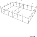
- a sequential set of images to illustrate the construction method using the Wall Trusses of the present invention comprises Figure 4 which illustrates a perspective view of the installed arrangement of Wall Trusses for two apartments, the Floor Shelf installed near the top of the upper Wall Truss; Figure 5 which illustrates a perspective view of a set of Wall Trusses with Floor Modules in a typical multi-story building using the Stacked Wall Truss Construction design and construction approach for multi-story buildings of the present invention; and Figure 6 which illustrates a perspective view of a set of Wall Trusses ready to receive a Floor Module which will be placed on the Floor Shelves in a typical multi-story building using the Stacked Wall Truss Construction design and construction approach for multi-story buildings of the present invention.
- the Wall Trusses can be interconnected to form two enclosed spaces A, B; and this form can be expanded in three dimensions to form a multi-story framework as shown in Figure 5 .
- the basic Wall Truss spaces A, B can be joined with a mating set of enclosed spaces C, D added to the top thereof to form a two-story framework.
- the Wall Truss spaces A, B include Floor Shelves as described above and shown in Figure 5 , and the Floor Modules are placed thereon to provide a floor for the Wall Truss spaces C, D.
- a corresponding set of two-story Wall Truss spaces E-H can be located juxtaposed to Wall Truss spaced A-D, separated therefrom by common area space J. This structure is illustrated in a more finished form in Figures 14 and 15 , which are described below.
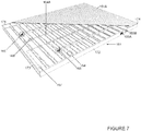
- FIGs 6 and 7 illustrate details of Floor Modules 161, 162 .
- Each Floor Module, such as 161 consists of a plurality of parallel oriented, spaced apart Floor Joists, such as Floor Joist 164, which has formed therein a plurality of cutouts 164A ( Figure 7 ) through which utilities can be routed.
- Floor Modules 161, 162 are the support for Floor Plates 161A, 162A, which provide a substrate for the flooring, such as a Topping Slab 1031 (illustrated in Figure 10 ).
- Figure 6 also illustrates the provision of foundation walls 170, 171, which have embedded therein Foundation Embed Plate Bolts on top of which are affixed Mating Members, as described below (collectively termed "Mating Anchors" herein).
- the Floor Modules 161, 162, with their respective Floor Plates 161A, 162A are installed on the Floor Shelves of enclosed spaces A, B.
- FIG 7 illustrates additional detail of a Floor Module 161, where the Floor Plate 161A is cut away in part to expose the Floor Joists 164.
- the Floor Joists 164 are capped at their ends with Capping Track 171, 172 which are interconnected at their ends with Floor Joists 173, 174 which do not have any openings formed therein.
- elements 171-174 create a solid perimeter surface frame for Floor Module 161 to enable a Topping Slab 1031 (illustrated in Figure 10 ) to be poured on top of Floor Plate 161A and to extend into the spaces between Floor Module 161 and the surrounding Wall Trusses as described below.
- Various utilities are mounted in Floor Module 161 by routing between adjacent Floor Joists 164 and through the openings 164A formed in Floor Joists 164.
- FIG. 8A and 8B illustrate a close-up view of openings 169A, 169B and the respective plumbing 165, 166 and electrical 167, 168 utility interconnects.
- Figure 9 is a cross-section view of an exterior wall of a multi-story building, where Wall Truss 3 is mounted on top of Wall Truss 1.
- the Wall Trusses 1, 3 comprise vertical columns 303, 311 interconnected by a Mating Member having a Floor Shelf 1021 segment.
- a cross-section of Horizontal Members 1051, 1052 are shown for illustrative purposes.
- Exterior Wall Slabs 1042, 1041 are affixed to Wall Trusses 1, 3, respectively.
- the Exterior Wall Slab 1042 is secured in place on the top side thereof, by the overhang of Floor Shelf 1021 turning in a downward direction.
- the bottom side of each Exterior Wall Slab 1041 is secured by the projection/wall pocket 921.
- the space between respective Exterior Wall Slabs 1041, 1042 can be filled by the application of a filler material, which provides protection from the elements.
- a filler material which provides protection from the elements.
- Wall Coverings 1011, 1012 are secured to the vertical columns 311, 301 in a conventional manner.
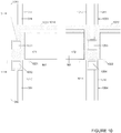
- Figure 10 illustrates a cross-section at the joint between two typical sets of stacked Wall Trusses 1-3 and 1003-1004. Additionally, Figure 10 shows the Topping Slab 1031 poured on top of the Floor Module 161and also filling the gaps (fluid receiving pockets) between the edges of the Floor Shelf 1021, 1022 and the Wall Truss 1, 1003.
- Figure 10 also shows a thin concrete Exterior Wall Panels 1041, 1042 utilized in the preferred embodiment, where this thin concrete Exterior Wall Panels 1041, 1042 are affixed to the Wall Trusses 3, 1 prior to the Wall Trusses 3, 1 being installed on the building, where the Exterior Wall Panels 1041, 1042 are on the outside of Wall Trusses 3, 1 in an exterior condition, and thin concrete Wall Panels 1013 - 1016used on Wall Trusses 3, 1, 1003, 1004 where it functions as a fireproof and soundproof interior separation as needed in a multi-story building.
- FIG 10 also illustrates only a portion of the Wall Trusses 1, 3, 1003, 1004 and coordinated components in the interest of clarity, due to the limited space available in the Figure.
- the Wall Trusses 1, 3 each contain a Wall Truss Column such as 301, 311, respectively, to which is affixed a concrete Wall Panel 1041-1042, in the case of Wall Truss Columns 311, 301, as the exterior finish of the building.
- Wall Truss Columns 311, 301 are interconnected to their respective adjacent Wall Truss Column (not shown) via two horizontal Wall Truss Beams, two of which 1051-1052, respectively, are illustrated in Figure 10 (as are horizontal Wall Truss Beams 1053, 1054 for Wall Trusses 1003, 1004).
- Floor Shelves 1021, 1022 are attached to the horizontal Wall Truss Beams 1052 and 1054, by welding, bolting, or some other structural connection, respectively, to receive Floor Module 161 which is the floor load bearing element between facing Floor Shelves 1021, 1022.
- the Floor Shelf 1021 runs the length of Wall Truss 1.
- the Floor Module 161as shown in Figures 6 and 7 is placed on top of the Floor Shelves 1021, 1022 and span the opening between the walls formed by the Wall Trusses 1, 3, 1003, 1004.
- the Floor Module 161 consists of a plurality of substantially parallel oriented Floor Joists 164 on top of which are placed a Deck 161A which provides a solid surface on top of which the Topping Slab 1031 can be poured.
- a thin Topping Slab 1031 of concrete is poured on top of the Deck 161A, and this Topping Slab 1031 also fills the space between the Floor Module 161 and the Wall Trusses 3, 1003.
- the Floor Module 161 shown in the preferred embodiment of Figures 6 , 7 , and 10 is framed with light gauge steel Floor Joists 164 spanning one direction and a Capping Track 171, 172 which caps and encloses the ends of the Floor Joists 164 in the Floor Module 161 on the two sides of the Floor Module 161 which have the ends of the light gauge joists.
- the Topping Slab 1031 also fills the void between Wall Trusses 3 and 1003 and other similar locations, since Capping Tracks 171, 172 and End Joists 173, 174 in combination with Floor Shelves 1021, 1022 form a pocket into which the concrete poured for Topping Slab 1031 can flow to create an integral structure (floor slab anchor) that locks the Floor Module 161 to the Wall Trusses 3, 1003.
- This concrete Topping Slab 1031 can be finished to become the final interior finish or can be the subfloor for carpeting, or tile, or wood flooring, or the like.
- Deck 161A is supported by Floor Module 161, and concrete floor finish Topping Slab 1031 is applied thereto.
- Figure 13 illustrates a typical Kitchen Module 1300 for a kitchen, which includes a stove/range 1305, a sink 1306, cabinets 1301-1304, 1309, light fixtures 1307, 1308 and the like.
- the utilities 1310, 1311 serving these appliances are run to interconnect points in the appliance module 1300, which utilities mate with the utilities that are pre-installed in the Floor Module 161 as disclosed above.
- the interconnection of the utilities 1310, 1311 can be done after the Topping Slab 1031 is installed which simplifies the construction of the finish in the dwelling unit.
- Figure 12 illustrates a typical roof installation comprising the conventional parallel oriented set of roof joists 1221, illustrated with the roof sheathing 1222 partially removed.
- the roof can be attached to the top floor of the multi-story building using conventional techniques to connect to Wall Trusses 1201-1204 and their Floor Modules 1211-1213 and can be of any style and finish.
- Figure 14 illustrates two apartment units 401, 402 and their respective walls 403-407.
- Walls 403 and 405 each consist of five Wall Truss Columns 451-455 and 456-460, respectively, which Wall Truss Columns are interconnected by pairs of Wall Truss Beams 411-414 and 415-418, respectively.
- walls 404, 406, 407 each consist of five Wall Truss Columns 461-465, 466-470, and 471-475, respectively, which Wall Truss Columns are interconnected by pairs of Wall Truss Beams 421-424, 431-434, 441-444, respectively.
- This plan view illustrates the location of the Wall Truss Beams, which are in practice two chords per span, one at the top of the Wall Truss Columns and one at the bottom of the Wall Truss Columns as diagrammed in Figure 5 .
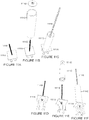
- Figures 11A - 11F illustrate a mechanism that can be used to transition from the customary poured concrete foundation 170 and 171 (in Figure 6 ) of a multi-story building to a precision dimensioned framing system that must lean on and be affixed to the field-poured concrete. It is almost impossible to precisely control the resulting finished dimensions of field poured concrete or embedments cast into the concrete.
- the precise dimension Wall Trusses require a corresponding precision at their affixment point to the foundation at each Wall Truss Column. Weld plates are commonly embedded in field-poured concrete as an attachment point for later stages of construction.
- Figure 11 shows an Anchor Member that includes a novel weld plate 1111A where it has been center drilled and a threaded steel rod 1111B or bolt is affixed to the weld plate 1111A with a threaded portion of the rod 1111B extending upward.
- the weld plate 1111A with threaded rod 1111B attached can be embedded in the concrete during pouring, and the embedment studs secure the weld plate 1111A with threaded bolt 1111B securely.
- a Mating Member 1111C could have a flat plate 1111Q with a hole in it welded to one end.
- This hole might be 1 3/8 inches, and the threaded rod might be 3/8 inches. If the rod were in perfect position, it would be in the center of this hole creating a 1 ⁇ 2 inch uniform gap all around it. However, the threaded rod could be out of position by up to 1 ⁇ 2 inch, and it would be simple and easy to slide the Mating Member 1111C into proper position, and then affix it with a large washer and nut 1111D, and likely subsequent welding, to the weld plate 1111A. A perfect starting point for a precision Wall Truss results.
- the Floor Shelf is a tray for the Floor Modules. So when the Wall Trusses are installed on a particular floor of a building, a continuous Floor Shelf has been created in hallways, rooms, apartment units, and outdoor balcony areas such that the Floor Modules of the pre-made hallways, rooms, apartment units, and outdoor balcony areas can be lifted with the crane (where these pre-made Floor Modules are staged for assembly in close proximity to the crane) and they are quickly and efficiently dropped into place.
- the Wall Trusses can either be a "braced frame” or a "Moment Frame or Special Moment Frame.”
- a braced frame a diagonal piece of steel or other brace is installed in at least one bay of each Wall Truss. The diagonal functions as a shear brace in that Wall Truss, greatly increasing its capacity to resist folding in the direction of the Wall Truss.
- a Special Moment frame is created when, by virtue of just the geometry of the Wall Truss and its members and their connection together, the Wall Truss has shear capacity to resist laying over in the direction of the Wall Truss and functions with the inherent shear capacity of a Vierendeel Truss.
- Moment Frames flex in the cycle loading of earthquakes and with wind loading, as opposed to just being a rigid braced frame; therefore, Moment Frames tend to perform better and are preferred in tall multi-story buildings and in high seismic load areas. Both implementations work, and the architecture and design engineering of the present art can be either.
- the Thin Concrete Wall Panel of the preferred embodiment of the multi-story building is either poured against the pre-made Wall Truss in an on-site forming system, or they are fabricated as another pre-made assembly that is simply affixed to the Wall Trusses. Either way, in the preferred embodiment of the present art, when you hoist a wall frame, it consists of the structural elements, installed utilities, walls, wall finishes, etc. There is no requirement to return to place hand laid brick as in-fill as is done in the traditional poured-in--place concrete buildings today. Hoist the Wall Trusses, place the Floor Modules, pour the Topping Slabs, connect the utilities that have been preinstalled in the Modular Elements at the Utility Interconnect Locations, then move onward and upward.
- Figure 14 illustrates a plan view of one floor of a partially completed multi-story building using the Stacked Prefabricated Structural Steel Wall
- Figure 6 illustrates a perspective view of several typical residential apartments of a multi-story building constructed using the Stacked Wall Truss Construction
- Figure 15 illustrates a typical completed multi-story building using the Stacked Wall Truss Construction.
- the present Stacked Wall Truss Constructions and their use in the construction of multi-story buildings departs from the traditional methods of constructing multi-story buildings by the use of prefabricated modular Wall Trusses that are interconnected in three dimensions to enable the rapid completion of building construction with improved quality of construction over that found in traditional multi-story building construction. Further, additional Modular Elements including Floor Modules and Kitchen Modules compliment the Wall Trusses to create a fully modular program of building construction that can be quickly and efficiently accomplished.
- the resultant building is really a structural steel frame without the use of traditional, heavy, individual stacking columns and beams, since the vertical Wall Trusses create smaller continuous vertical steel elements by virtue of the design configuration and vertical assembly of the Wall Trusses, thereby building construction becomes a process of stacking Wall Trusses, not individual, heavy steel columns and beams.
- An inner Wall Truss Column Mating Member can be placed hanging out of the bottom of each Wall Truss or sticking out of the top of lower Wall Trusses to enable a Wall Truss placement to be near perfectly positioned on top of the installed Wall Truss below.
Landscapes
- Engineering & Computer Science (AREA)
- Architecture (AREA)
- Physics & Mathematics (AREA)
- Electromagnetism (AREA)
- Civil Engineering (AREA)
- Structural Engineering (AREA)
- Conveying And Assembling Of Building Elements In Situ (AREA)
- Load-Bearing And Curtain Walls (AREA)
- Joining Of Building Structures In Genera (AREA)
- Buildings Adapted To Withstand Abnormal External Influences (AREA)
Applications Claiming Priority (2)
| Application Number | Priority Date | Filing Date | Title |
|---|---|---|---|
| US201662298054P | 2016-02-22 | 2016-02-22 | |
| PCT/US2017/013894 WO2017146837A1 (en) | 2016-02-22 | 2017-01-18 | Stacked structural steel wall trusses |
Publications (2)
| Publication Number | Publication Date |
|---|---|
| EP3420154A1 EP3420154A1 (en) | 2019-01-02 |
| EP3420154B1 true EP3420154B1 (en) | 2020-06-24 |
Family
ID=57944552
Family Applications (4)
| Application Number | Title | Priority Date | Filing Date |
|---|---|---|---|
| EP17702487.4A Active EP3420152B1 (en) | 2016-02-22 | 2017-01-18 | Method for constructing multi-story buildings using stacked structural steel wall trusses |
| EP17702486.6A Active EP3420151B1 (en) | 2016-02-22 | 2017-01-18 | Method for constructing multi-story buildings using stacked structural steel wall trusses |
| EP17702720.8A Active EP3420153B1 (en) | 2016-02-22 | 2017-01-18 | Constructing multi-story buildings using stacked structural steel wall trusses |
| EP17704121.7A Active EP3420154B1 (en) | 2016-02-22 | 2017-01-18 | Stacked structural steel wall trusses |
Family Applications Before (3)
| Application Number | Title | Priority Date | Filing Date |
|---|---|---|---|
| EP17702487.4A Active EP3420152B1 (en) | 2016-02-22 | 2017-01-18 | Method for constructing multi-story buildings using stacked structural steel wall trusses |
| EP17702486.6A Active EP3420151B1 (en) | 2016-02-22 | 2017-01-18 | Method for constructing multi-story buildings using stacked structural steel wall trusses |
| EP17702720.8A Active EP3420153B1 (en) | 2016-02-22 | 2017-01-18 | Constructing multi-story buildings using stacked structural steel wall trusses |
Country Status (13)
| Country | Link |
|---|---|
| US (4) | US10584485B2 (ar) |
| EP (4) | EP3420152B1 (ar) |
| JP (4) | JP6946349B2 (ar) |
| KR (4) | KR20180115735A (ar) |
| CN (4) | CN108779635B (ar) |
| AU (4) | AU2017222253A1 (ar) |
| BR (4) | BR112018017096A2 (ar) |
| CA (4) | CA3015699A1 (ar) |
| ES (4) | ES2809715T3 (ar) |
| MX (3) | MX2018010069A (ar) |
| PH (4) | PH12018501755A1 (ar) |
| SA (4) | SA518392237B1 (ar) |
| WO (4) | WO2017146838A1 (ar) |
Families Citing this family (13)
| Publication number | Priority date | Publication date | Assignee | Title |
|---|---|---|---|---|
| US10508432B2 (en) * | 2018-04-24 | 2019-12-17 | Ss-20 Building Systems, Inc. | Connection for stacking post system for multistory building construction |
| CN108643347B (zh) * | 2018-04-27 | 2020-11-24 | 长江大学 | 型钢混凝土框架-钢筋混凝土墙板混合结构体系 |
| EP3594422B1 (en) * | 2018-07-09 | 2021-01-06 | Yau Lee Wah Concrete Precast Products (Shenzhen) Company Limited | Modular integrated building and construction method thereof |
| CN109440923A (zh) * | 2018-12-17 | 2019-03-08 | 贵州大学 | 一种不规则蜂窝状空间网格盒式结构及制作方法 |
| KR102092608B1 (ko) * | 2019-03-21 | 2020-03-25 | 주식회사 썬앤라이트 | 스마트 모듈러 |
| WO2021007653A1 (en) * | 2019-07-15 | 2021-01-21 | Intelligent City Inc. | Facade panel with integrated window system |
| CN110565800A (zh) * | 2019-09-16 | 2019-12-13 | 青岛理工大学 | 一种装配节点模块、集成建造系统及集成建造方法 |
| US11421418B2 (en) | 2019-12-20 | 2022-08-23 | Universal City Studios Llc | Truss with integrated wiring |
| US11692341B2 (en) * | 2020-07-22 | 2023-07-04 | Nano And Advanced Materials Institute Limited | Lightweight concrete modular integrated construction (MIC) system |
| EP4225999A1 (en) | 2020-10-06 | 2023-08-16 | Charles Joseph EL KHOURY | Modular panels and system for using said panels |
| US20230417049A1 (en) * | 2020-10-22 | 2023-12-28 | Innovative Building Technologies, Llc | Pre-manufactured load bearing walls for a multi-story building |
| CN114033221B (zh) * | 2021-11-05 | 2023-09-12 | 中建海龙科技有限公司 | 一种钢结构房屋箱及其生产工艺 |
| CN114232843B (zh) * | 2021-12-16 | 2023-08-08 | 中建五局第三建设有限公司 | 一种全装配式建筑及其施工方法 |
Family Cites Families (28)
| Publication number | Priority date | Publication date | Assignee | Title |
|---|---|---|---|---|
| US1174724A (en) * | 1914-04-07 | 1916-03-07 | Hans Honigmann | Automatic feeding device for platen printing-presses. |
| FR1174724A (fr) * | 1957-04-26 | 1959-03-16 | Sous-ensemble préfabriqué pour bâtiments et autres constructions et ensembles en comportant application | |
| US5012622A (en) * | 1985-03-05 | 1991-05-07 | Shimizu Construction Co., Ltd. | Structural filler filled steel tube column |
| JPS62160337A (ja) * | 1985-12-28 | 1987-07-16 | 清水建設株式会社 | アンボンド充填鋼管構造 |
| JP3234398B2 (ja) * | 1994-04-01 | 2001-12-04 | 新日本製鐵株式会社 | 鋼管の継手構造 |
| JPH08311991A (ja) * | 1995-05-17 | 1996-11-26 | Taisei Corp | 鋼管柱の継手方法 |
| JPH094052A (ja) * | 1995-06-21 | 1997-01-07 | Sekisui Chem Co Ltd | 柱頭柱脚間接合構造及び柱脚基礎間接合構造並びにユニット建物 |
| JPH09317003A (ja) * | 1996-05-28 | 1997-12-09 | Shimizu Corp | 鋼管柱 |
| JP3121557B2 (ja) * | 1997-03-14 | 2001-01-09 | ミサワホーム株式会社 | 建物ユニット及びユニット建物 |
| JP4186371B2 (ja) * | 2000-02-17 | 2008-11-26 | Jfeスチール株式会社 | 梁と根太との連結構造 |
| US6625937B1 (en) * | 2000-12-27 | 2003-09-30 | Sunrise Holding, Ltd. | Modular building and method of construction |
| JP2004316278A (ja) * | 2003-04-17 | 2004-11-11 | Maeda Corp | 鋼管柱脚部の構造 |
| JP4748637B2 (ja) * | 2003-08-29 | 2011-08-17 | 株式会社サトコウ | 建物ユニットの接合構造 |
| US8234827B1 (en) * | 2005-09-01 | 2012-08-07 | Schroeder Sr Robert | Express framing building construction system |
| JP2008190261A (ja) * | 2007-02-06 | 2008-08-21 | Ysc:Kk | 建築物 |
| JP2009062717A (ja) * | 2007-09-06 | 2009-03-26 | Union Kenzai Builder:Kk | 柱脚部の固定構造、鋼管柱材、該鋼管柱材を備えたパネル体 |
| US8661755B2 (en) * | 2008-01-24 | 2014-03-04 | Nucor Corporation | Composite wall system |
| CN101265723B (zh) * | 2008-05-07 | 2012-08-15 | 北京太空板业股份有限公司 | 由复合建筑板材组装而成的建筑结构体系及建造方法 |
| CN101368428B (zh) * | 2008-07-18 | 2011-07-20 | 徐尉 | 一种预制件房屋及其建筑方法 |
| HUE032062T2 (en) * | 2009-12-18 | 2017-08-28 | Patco Llc | Building structural element system |
| US8720154B1 (en) * | 2010-06-17 | 2014-05-13 | James P. Horne | Cold-formed steel structural wall and floor framing system |
| CN201952898U (zh) * | 2010-09-06 | 2011-08-31 | 北京诚栋国际营地集成房屋有限公司 | 拆装式单层平屋顶活动房屋 |
| JP5755458B2 (ja) * | 2011-01-31 | 2015-07-29 | 旭化成ホームズ株式会社 | デッキプレートパネル及びそれを用いた床構造 |
| US20120240482A1 (en) * | 2011-03-22 | 2012-09-27 | XSite Modular | Components for a Modular High-Rise Structures And Method For Assembling Same |
| EP2790883A4 (en) | 2011-12-14 | 2015-07-22 | Marion Invest Ltd | APPARATUS, SYSTEMS AND METHODS FOR MODULAR CONSTRUCTION |
| CN103382741B (zh) * | 2013-06-27 | 2016-05-25 | 张建忠 | 一种预制板的固定连接结构 |
| WO2016009411A1 (es) * | 2014-07-17 | 2016-01-21 | Sistemas De Construcción Industrial S.A.S. – Sisdeco | Sistema de construcción industrial adaptable, con climatización natural |
| CN104314201A (zh) * | 2014-11-17 | 2015-01-28 | 菏泽霸王机械有限公司 | 一种轻质钢结构复合保温墙体 |
-
2017
- 2017-01-18 EP EP17702487.4A patent/EP3420152B1/en active Active
- 2017-01-18 KR KR1020187026727A patent/KR20180115735A/ko unknown
- 2017-01-18 BR BR112018017096A patent/BR112018017096A2/pt not_active Application Discontinuation
- 2017-01-18 CA CA3015699A patent/CA3015699A1/en not_active Abandoned
- 2017-01-18 MX MX2018010069A patent/MX2018010069A/es unknown
- 2017-01-18 BR BR112018017006-2A patent/BR112018017006A2/pt not_active Application Discontinuation
- 2017-01-18 EP EP17702486.6A patent/EP3420151B1/en active Active
- 2017-01-18 EP EP17702720.8A patent/EP3420153B1/en active Active
- 2017-01-18 BR BR112018017093A patent/BR112018017093A2/pt not_active Application Discontinuation
- 2017-01-18 AU AU2017222253A patent/AU2017222253A1/en not_active Abandoned
- 2017-01-18 US US16/076,689 patent/US10584485B2/en not_active Expired - Fee Related
- 2017-01-18 MX MX2018010068A patent/MX2018010068A/es unknown
- 2017-01-18 CA CA3014783A patent/CA3014783A1/en not_active Abandoned
- 2017-01-18 AU AU2017222252A patent/AU2017222252A1/en not_active Abandoned
- 2017-01-18 JP JP2018562503A patent/JP6946349B2/ja active Active
- 2017-01-18 WO PCT/US2017/013902 patent/WO2017146838A1/en active Application Filing
- 2017-01-18 ES ES17702720T patent/ES2809715T3/es active Active
- 2017-01-18 AU AU2017222254A patent/AU2017222254A1/en not_active Abandoned
- 2017-01-18 CN CN201780012812.XA patent/CN108779635B/zh not_active Expired - Fee Related
- 2017-01-18 KR KR1020187026730A patent/KR20180115737A/ko unknown
- 2017-01-18 CN CN201780012781.8A patent/CN108779634B/zh not_active Expired - Fee Related
- 2017-01-18 JP JP2018562501A patent/JP2019509414A/ja active Pending
- 2017-01-18 EP EP17704121.7A patent/EP3420154B1/en active Active
- 2017-01-18 BR BR112018017083A patent/BR112018017083A2/pt not_active Application Discontinuation
- 2017-01-18 JP JP2018562502A patent/JP6946348B2/ja active Active
- 2017-01-18 KR KR1020187026731A patent/KR20180115738A/ko unknown
- 2017-01-18 WO PCT/US2017/013893 patent/WO2017146836A1/en active Application Filing
- 2017-01-18 JP JP2018562504A patent/JP6946350B2/ja active Active
- 2017-01-18 MX MX2018010070A patent/MX2018010070A/es unknown
- 2017-01-18 US US16/076,688 patent/US10584484B2/en not_active Expired - Fee Related
- 2017-01-18 KR KR1020187026728A patent/KR20180115736A/ko unknown
- 2017-01-18 ES ES17702487T patent/ES2795873T3/es active Active
- 2017-01-18 CA CA3014758A patent/CA3014758A1/en not_active Abandoned
- 2017-01-18 AU AU2017222255A patent/AU2017222255A1/en not_active Abandoned
- 2017-01-18 US US16/076,692 patent/US10577793B2/en not_active Expired - Fee Related
- 2017-01-18 US US16/076,691 patent/US10577792B2/en not_active Expired - Fee Related
- 2017-01-18 WO PCT/US2017/013894 patent/WO2017146837A1/en active Application Filing
- 2017-01-18 CN CN201780012843.5A patent/CN108779636B/zh not_active Expired - Fee Related
- 2017-01-18 ES ES17702486T patent/ES2796730T3/es active Active
- 2017-01-18 WO PCT/US2017/013903 patent/WO2017146839A1/en active Application Filing
- 2017-01-18 CA CA3014756A patent/CA3014756A1/en not_active Abandoned
- 2017-01-18 CN CN201780012803.0A patent/CN109072604B/zh not_active Expired - Fee Related
- 2017-01-18 ES ES17704121T patent/ES2809717T3/es active Active
-
2018
- 2018-08-16 SA SA518392237A patent/SA518392237B1/ar unknown
- 2018-08-16 SA SA518392232A patent/SA518392232B1/ar unknown
- 2018-08-16 SA SA518392231A patent/SA518392231B1/ar unknown
- 2018-08-17 PH PH12018501755A patent/PH12018501755A1/en unknown
- 2018-08-17 PH PH12018501752A patent/PH12018501752A1/en unknown
- 2018-08-17 PH PH12018501754A patent/PH12018501754A1/en unknown
- 2018-08-17 PH PH12018501753A patent/PH12018501753A1/en unknown
- 2018-08-19 SA SA518392249A patent/SA518392249B1/ar unknown
Non-Patent Citations (1)
| Title |
|---|
| None * |
Also Published As
Similar Documents
| Publication | Publication Date | Title |
|---|---|---|
| EP3420154B1 (en) | Stacked structural steel wall trusses | |
| AU2017414764A1 (en) | Wall module incorporating cellular concrete in a stacking structural steel wall frame |
Legal Events
| Date | Code | Title | Description |
|---|---|---|---|
| STAA | Information on the status of an ep patent application or granted ep patent |
Free format text: STATUS: UNKNOWN |
|
| STAA | Information on the status of an ep patent application or granted ep patent |
Free format text: STATUS: THE INTERNATIONAL PUBLICATION HAS BEEN MADE |
|
| PUAI | Public reference made under article 153(3) epc to a published international application that has entered the european phase |
Free format text: ORIGINAL CODE: 0009012 |
|
| STAA | Information on the status of an ep patent application or granted ep patent |
Free format text: STATUS: REQUEST FOR EXAMINATION WAS MADE |
|
| 17P | Request for examination filed |
Effective date: 20180731 |
|
| AK | Designated contracting states |
Kind code of ref document: A1 Designated state(s): AL AT BE BG CH CY CZ DE DK EE ES FI FR GB GR HR HU IE IS IT LI LT LU LV MC MK MT NL NO PL PT RO RS SE SI SK SM TR |
|
| AX | Request for extension of the european patent |
Extension state: BA ME |
|
| DAV | Request for validation of the european patent (deleted) | ||
| DAX | Request for extension of the european patent (deleted) | ||
| GRAP | Despatch of communication of intention to grant a patent |
Free format text: ORIGINAL CODE: EPIDOSNIGR1 |
|
| STAA | Information on the status of an ep patent application or granted ep patent |
Free format text: STATUS: GRANT OF PATENT IS INTENDED |
|
| INTG | Intention to grant announced |
Effective date: 20191016 |
|
| GRAJ | Information related to disapproval of communication of intention to grant by the applicant or resumption of examination proceedings by the epo deleted |
Free format text: ORIGINAL CODE: EPIDOSDIGR1 |
|
| STAA | Information on the status of an ep patent application or granted ep patent |
Free format text: STATUS: REQUEST FOR EXAMINATION WAS MADE |
|
| GRAP | Despatch of communication of intention to grant a patent |
Free format text: ORIGINAL CODE: EPIDOSNIGR1 |
|
| STAA | Information on the status of an ep patent application or granted ep patent |
Free format text: STATUS: GRANT OF PATENT IS INTENDED |
|
| INTC | Intention to grant announced (deleted) | ||
| INTG | Intention to grant announced |
Effective date: 20200122 |
|
| GRAS | Grant fee paid |
Free format text: ORIGINAL CODE: EPIDOSNIGR3 |
|
| GRAA | (expected) grant |
Free format text: ORIGINAL CODE: 0009210 |
|
| STAA | Information on the status of an ep patent application or granted ep patent |
Free format text: STATUS: THE PATENT HAS BEEN GRANTED |
|
| AK | Designated contracting states |
Kind code of ref document: B1 Designated state(s): AL AT BE BG CH CY CZ DE DK EE ES FI FR GB GR HR HU IE IS IT LI LT LU LV MC MK MT NL NO PL PT RO RS SE SI SK SM TR |
|
| REG | Reference to a national code |
Ref country code: GB Ref legal event code: FG4D |
|
| REG | Reference to a national code |
Ref country code: CH Ref legal event code: EP |
|
| REG | Reference to a national code |
Ref country code: DE Ref legal event code: R096 Ref document number: 602017018651 Country of ref document: DE |
|
| REG | Reference to a national code |
Ref country code: AT Ref legal event code: REF Ref document number: 1284033 Country of ref document: AT Kind code of ref document: T Effective date: 20200715 |
|
| REG | Reference to a national code |
Ref country code: IE Ref legal event code: FG4D |
|
| PG25 | Lapsed in a contracting state [announced via postgrant information from national office to epo] |
Ref country code: NO Free format text: LAPSE BECAUSE OF FAILURE TO SUBMIT A TRANSLATION OF THE DESCRIPTION OR TO PAY THE FEE WITHIN THE PRESCRIBED TIME-LIMIT Effective date: 20200924 Ref country code: FI Free format text: LAPSE BECAUSE OF FAILURE TO SUBMIT A TRANSLATION OF THE DESCRIPTION OR TO PAY THE FEE WITHIN THE PRESCRIBED TIME-LIMIT Effective date: 20200624 Ref country code: GR Free format text: LAPSE BECAUSE OF FAILURE TO SUBMIT A TRANSLATION OF THE DESCRIPTION OR TO PAY THE FEE WITHIN THE PRESCRIBED TIME-LIMIT Effective date: 20200925 Ref country code: LT Free format text: LAPSE BECAUSE OF FAILURE TO SUBMIT A TRANSLATION OF THE DESCRIPTION OR TO PAY THE FEE WITHIN THE PRESCRIBED TIME-LIMIT Effective date: 20200624 Ref country code: SE Free format text: LAPSE BECAUSE OF FAILURE TO SUBMIT A TRANSLATION OF THE DESCRIPTION OR TO PAY THE FEE WITHIN THE PRESCRIBED TIME-LIMIT Effective date: 20200624 |
|
| REG | Reference to a national code |
Ref country code: LT Ref legal event code: MG4D |
|
| PG25 | Lapsed in a contracting state [announced via postgrant information from national office to epo] |
Ref country code: BG Free format text: LAPSE BECAUSE OF FAILURE TO SUBMIT A TRANSLATION OF THE DESCRIPTION OR TO PAY THE FEE WITHIN THE PRESCRIBED TIME-LIMIT Effective date: 20200924 Ref country code: RS Free format text: LAPSE BECAUSE OF FAILURE TO SUBMIT A TRANSLATION OF THE DESCRIPTION OR TO PAY THE FEE WITHIN THE PRESCRIBED TIME-LIMIT Effective date: 20200624 Ref country code: LV Free format text: LAPSE BECAUSE OF FAILURE TO SUBMIT A TRANSLATION OF THE DESCRIPTION OR TO PAY THE FEE WITHIN THE PRESCRIBED TIME-LIMIT Effective date: 20200624 Ref country code: HR Free format text: LAPSE BECAUSE OF FAILURE TO SUBMIT A TRANSLATION OF THE DESCRIPTION OR TO PAY THE FEE WITHIN THE PRESCRIBED TIME-LIMIT Effective date: 20200624 |
|
| REG | Reference to a national code |
Ref country code: NL Ref legal event code: MP Effective date: 20200624 |
|
| REG | Reference to a national code |
Ref country code: AT Ref legal event code: MK05 Ref document number: 1284033 Country of ref document: AT Kind code of ref document: T Effective date: 20200624 |
|
| PG25 | Lapsed in a contracting state [announced via postgrant information from national office to epo] |
Ref country code: AL Free format text: LAPSE BECAUSE OF FAILURE TO SUBMIT A TRANSLATION OF THE DESCRIPTION OR TO PAY THE FEE WITHIN THE PRESCRIBED TIME-LIMIT Effective date: 20200624 Ref country code: NL Free format text: LAPSE BECAUSE OF FAILURE TO SUBMIT A TRANSLATION OF THE DESCRIPTION OR TO PAY THE FEE WITHIN THE PRESCRIBED TIME-LIMIT Effective date: 20200624 |
|
| PG25 | Lapsed in a contracting state [announced via postgrant information from national office to epo] |
Ref country code: SM Free format text: LAPSE BECAUSE OF FAILURE TO SUBMIT A TRANSLATION OF THE DESCRIPTION OR TO PAY THE FEE WITHIN THE PRESCRIBED TIME-LIMIT Effective date: 20200624 Ref country code: EE Free format text: LAPSE BECAUSE OF FAILURE TO SUBMIT A TRANSLATION OF THE DESCRIPTION OR TO PAY THE FEE WITHIN THE PRESCRIBED TIME-LIMIT Effective date: 20200624 Ref country code: AT Free format text: LAPSE BECAUSE OF FAILURE TO SUBMIT A TRANSLATION OF THE DESCRIPTION OR TO PAY THE FEE WITHIN THE PRESCRIBED TIME-LIMIT Effective date: 20200624 Ref country code: PT Free format text: LAPSE BECAUSE OF FAILURE TO SUBMIT A TRANSLATION OF THE DESCRIPTION OR TO PAY THE FEE WITHIN THE PRESCRIBED TIME-LIMIT Effective date: 20201026 Ref country code: CZ Free format text: LAPSE BECAUSE OF FAILURE TO SUBMIT A TRANSLATION OF THE DESCRIPTION OR TO PAY THE FEE WITHIN THE PRESCRIBED TIME-LIMIT Effective date: 20200624 Ref country code: RO Free format text: LAPSE BECAUSE OF FAILURE TO SUBMIT A TRANSLATION OF THE DESCRIPTION OR TO PAY THE FEE WITHIN THE PRESCRIBED TIME-LIMIT Effective date: 20200624 |
|
| PGFP | Annual fee paid to national office [announced via postgrant information from national office to epo] |
Ref country code: FR Payment date: 20201130 Year of fee payment: 5 Ref country code: GB Payment date: 20201130 Year of fee payment: 5 |
|
| PG25 | Lapsed in a contracting state [announced via postgrant information from national office to epo] |
Ref country code: IS Free format text: LAPSE BECAUSE OF FAILURE TO SUBMIT A TRANSLATION OF THE DESCRIPTION OR TO PAY THE FEE WITHIN THE PRESCRIBED TIME-LIMIT Effective date: 20201024 Ref country code: SK Free format text: LAPSE BECAUSE OF FAILURE TO SUBMIT A TRANSLATION OF THE DESCRIPTION OR TO PAY THE FEE WITHIN THE PRESCRIBED TIME-LIMIT Effective date: 20200624 Ref country code: PL Free format text: LAPSE BECAUSE OF FAILURE TO SUBMIT A TRANSLATION OF THE DESCRIPTION OR TO PAY THE FEE WITHIN THE PRESCRIBED TIME-LIMIT Effective date: 20200624 |
|
| REG | Reference to a national code |
Ref country code: ES Ref legal event code: FG2A Ref document number: 2809717 Country of ref document: ES Kind code of ref document: T3 Effective date: 20210305 |
|
| REG | Reference to a national code |
Ref country code: DE Ref legal event code: R097 Ref document number: 602017018651 Country of ref document: DE |
|
| PG25 | Lapsed in a contracting state [announced via postgrant information from national office to epo] |
Ref country code: DK Free format text: LAPSE BECAUSE OF FAILURE TO SUBMIT A TRANSLATION OF THE DESCRIPTION OR TO PAY THE FEE WITHIN THE PRESCRIBED TIME-LIMIT Effective date: 20200624 |
|
| PGFP | Annual fee paid to national office [announced via postgrant information from national office to epo] |
Ref country code: IT Payment date: 20210122 Year of fee payment: 5 |
|
| PLBE | No opposition filed within time limit |
Free format text: ORIGINAL CODE: 0009261 |
|
| STAA | Information on the status of an ep patent application or granted ep patent |
Free format text: STATUS: NO OPPOSITION FILED WITHIN TIME LIMIT |
|
| PGFP | Annual fee paid to national office [announced via postgrant information from national office to epo] |
Ref country code: TR Payment date: 20210112 Year of fee payment: 5 Ref country code: ES Payment date: 20210201 Year of fee payment: 5 Ref country code: DE Payment date: 20210127 Year of fee payment: 5 |
|
| 26N | No opposition filed |
Effective date: 20210325 |
|
| PG25 | Lapsed in a contracting state [announced via postgrant information from national office to epo] |
Ref country code: SI Free format text: LAPSE BECAUSE OF FAILURE TO SUBMIT A TRANSLATION OF THE DESCRIPTION OR TO PAY THE FEE WITHIN THE PRESCRIBED TIME-LIMIT Effective date: 20200624 Ref country code: MC Free format text: LAPSE BECAUSE OF FAILURE TO SUBMIT A TRANSLATION OF THE DESCRIPTION OR TO PAY THE FEE WITHIN THE PRESCRIBED TIME-LIMIT Effective date: 20200624 |
|
| REG | Reference to a national code |
Ref country code: CH Ref legal event code: PL |
|
| PG25 | Lapsed in a contracting state [announced via postgrant information from national office to epo] |
Ref country code: LU Free format text: LAPSE BECAUSE OF NON-PAYMENT OF DUE FEES Effective date: 20210118 |
|
| REG | Reference to a national code |
Ref country code: BE Ref legal event code: MM Effective date: 20210131 |
|
| PG25 | Lapsed in a contracting state [announced via postgrant information from national office to epo] |
Ref country code: CH Free format text: LAPSE BECAUSE OF NON-PAYMENT OF DUE FEES Effective date: 20210131 Ref country code: LI Free format text: LAPSE BECAUSE OF NON-PAYMENT OF DUE FEES Effective date: 20210131 |
|
| PG25 | Lapsed in a contracting state [announced via postgrant information from national office to epo] |
Ref country code: IE Free format text: LAPSE BECAUSE OF NON-PAYMENT OF DUE FEES Effective date: 20210118 |
|
| PG25 | Lapsed in a contracting state [announced via postgrant information from national office to epo] |
Ref country code: BE Free format text: LAPSE BECAUSE OF NON-PAYMENT OF DUE FEES Effective date: 20210131 |
|
| REG | Reference to a national code |
Ref country code: DE Ref legal event code: R119 Ref document number: 602017018651 Country of ref document: DE |
|
| GBPC | Gb: european patent ceased through non-payment of renewal fee |
Effective date: 20220118 |
|
| PG25 | Lapsed in a contracting state [announced via postgrant information from national office to epo] |
Ref country code: GB Free format text: LAPSE BECAUSE OF NON-PAYMENT OF DUE FEES Effective date: 20220118 Ref country code: DE Free format text: LAPSE BECAUSE OF NON-PAYMENT OF DUE FEES Effective date: 20220802 |
|
| PG25 | Lapsed in a contracting state [announced via postgrant information from national office to epo] |
Ref country code: FR Free format text: LAPSE BECAUSE OF NON-PAYMENT OF DUE FEES Effective date: 20220131 |
|
| PG25 | Lapsed in a contracting state [announced via postgrant information from national office to epo] |
Ref country code: IT Free format text: LAPSE BECAUSE OF NON-PAYMENT OF DUE FEES Effective date: 20220118 |
|
| REG | Reference to a national code |
Ref country code: ES Ref legal event code: FD2A Effective date: 20230227 |
|
| PG25 | Lapsed in a contracting state [announced via postgrant information from national office to epo] |
Ref country code: ES Free format text: LAPSE BECAUSE OF NON-PAYMENT OF DUE FEES Effective date: 20220119 |
|
| PG25 | Lapsed in a contracting state [announced via postgrant information from national office to epo] |
Ref country code: CY Free format text: LAPSE BECAUSE OF FAILURE TO SUBMIT A TRANSLATION OF THE DESCRIPTION OR TO PAY THE FEE WITHIN THE PRESCRIBED TIME-LIMIT Effective date: 20200624 |
|
| PG25 | Lapsed in a contracting state [announced via postgrant information from national office to epo] |
Ref country code: HU Free format text: LAPSE BECAUSE OF FAILURE TO SUBMIT A TRANSLATION OF THE DESCRIPTION OR TO PAY THE FEE WITHIN THE PRESCRIBED TIME-LIMIT; INVALID AB INITIO Effective date: 20170118 |
|
| PG25 | Lapsed in a contracting state [announced via postgrant information from national office to epo] |
Ref country code: MK Free format text: LAPSE BECAUSE OF FAILURE TO SUBMIT A TRANSLATION OF THE DESCRIPTION OR TO PAY THE FEE WITHIN THE PRESCRIBED TIME-LIMIT Effective date: 20200624 |