EP3419829B1 - Procédé permettant de détecter une perturbation dans l'éjection des gouttelettes d'une tête d'impression à jet d'encre - Google Patents
Procédé permettant de détecter une perturbation dans l'éjection des gouttelettes d'une tête d'impression à jet d'encre Download PDFInfo
- Publication number
- EP3419829B1 EP3419829B1 EP17705614.0A EP17705614A EP3419829B1 EP 3419829 B1 EP3419829 B1 EP 3419829B1 EP 17705614 A EP17705614 A EP 17705614A EP 3419829 B1 EP3419829 B1 EP 3419829B1
- Authority
- EP
- European Patent Office
- Prior art keywords
- disturbance
- resonance frequency
- pulse
- pressure chamber
- determined
- Prior art date
- Legal status (The legal status is an assumption and is not a legal conclusion. Google has not performed a legal analysis and makes no representation as to the accuracy of the status listed.)
- Active
Links
Images


Classifications
-
- B—PERFORMING OPERATIONS; TRANSPORTING
- B41—PRINTING; LINING MACHINES; TYPEWRITERS; STAMPS
- B41J—TYPEWRITERS; SELECTIVE PRINTING MECHANISMS, i.e. MECHANISMS PRINTING OTHERWISE THAN FROM A FORME; CORRECTION OF TYPOGRAPHICAL ERRORS
- B41J2/00—Typewriters or selective printing mechanisms characterised by the printing or marking process for which they are designed
- B41J2/005—Typewriters or selective printing mechanisms characterised by the printing or marking process for which they are designed characterised by bringing liquid or particles selectively into contact with a printing material
- B41J2/01—Ink jet
- B41J2/015—Ink jet characterised by the jet generation process
- B41J2/04—Ink jet characterised by the jet generation process generating single droplets or particles on demand
- B41J2/045—Ink jet characterised by the jet generation process generating single droplets or particles on demand by pressure, e.g. electromechanical transducers
- B41J2/04501—Control methods or devices therefor, e.g. driver circuits, control circuits
- B41J2/0451—Control methods or devices therefor, e.g. driver circuits, control circuits for detecting failure, e.g. clogging, malfunctioning actuator
-
- B—PERFORMING OPERATIONS; TRANSPORTING
- B41—PRINTING; LINING MACHINES; TYPEWRITERS; STAMPS
- B41J—TYPEWRITERS; SELECTIVE PRINTING MECHANISMS, i.e. MECHANISMS PRINTING OTHERWISE THAN FROM A FORME; CORRECTION OF TYPOGRAPHICAL ERRORS
- B41J2/00—Typewriters or selective printing mechanisms characterised by the printing or marking process for which they are designed
- B41J2/005—Typewriters or selective printing mechanisms characterised by the printing or marking process for which they are designed characterised by bringing liquid or particles selectively into contact with a printing material
- B41J2/01—Ink jet
- B41J2/015—Ink jet characterised by the jet generation process
- B41J2/04—Ink jet characterised by the jet generation process generating single droplets or particles on demand
- B41J2/045—Ink jet characterised by the jet generation process generating single droplets or particles on demand by pressure, e.g. electromechanical transducers
- B41J2/04501—Control methods or devices therefor, e.g. driver circuits, control circuits
- B41J2/04588—Control methods or devices therefor, e.g. driver circuits, control circuits using a specific waveform
-
- B—PERFORMING OPERATIONS; TRANSPORTING
- B41—PRINTING; LINING MACHINES; TYPEWRITERS; STAMPS
- B41J—TYPEWRITERS; SELECTIVE PRINTING MECHANISMS, i.e. MECHANISMS PRINTING OTHERWISE THAN FROM A FORME; CORRECTION OF TYPOGRAPHICAL ERRORS
- B41J2/00—Typewriters or selective printing mechanisms characterised by the printing or marking process for which they are designed
- B41J2/005—Typewriters or selective printing mechanisms characterised by the printing or marking process for which they are designed characterised by bringing liquid or particles selectively into contact with a printing material
- B41J2/01—Ink jet
- B41J2/015—Ink jet characterised by the jet generation process
- B41J2/04—Ink jet characterised by the jet generation process generating single droplets or particles on demand
- B41J2/045—Ink jet characterised by the jet generation process generating single droplets or particles on demand by pressure, e.g. electromechanical transducers
- B41J2/04501—Control methods or devices therefor, e.g. driver circuits, control circuits
- B41J2/04596—Non-ejecting pulses
-
- B—PERFORMING OPERATIONS; TRANSPORTING
- B41—PRINTING; LINING MACHINES; TYPEWRITERS; STAMPS
- B41J—TYPEWRITERS; SELECTIVE PRINTING MECHANISMS, i.e. MECHANISMS PRINTING OTHERWISE THAN FROM A FORME; CORRECTION OF TYPOGRAPHICAL ERRORS
- B41J2/00—Typewriters or selective printing mechanisms characterised by the printing or marking process for which they are designed
- B41J2/005—Typewriters or selective printing mechanisms characterised by the printing or marking process for which they are designed characterised by bringing liquid or particles selectively into contact with a printing material
- B41J2/01—Ink jet
- B41J2/135—Nozzles
- B41J2/14—Structure thereof only for on-demand ink jet heads
-
- B—PERFORMING OPERATIONS; TRANSPORTING
- B41—PRINTING; LINING MACHINES; TYPEWRITERS; STAMPS
- B41J—TYPEWRITERS; SELECTIVE PRINTING MECHANISMS, i.e. MECHANISMS PRINTING OTHERWISE THAN FROM A FORME; CORRECTION OF TYPOGRAPHICAL ERRORS
- B41J2/00—Typewriters or selective printing mechanisms characterised by the printing or marking process for which they are designed
- B41J2/005—Typewriters or selective printing mechanisms characterised by the printing or marking process for which they are designed characterised by bringing liquid or particles selectively into contact with a printing material
- B41J2/01—Ink jet
- B41J2/21—Ink jet for multi-colour printing
- B41J2/2132—Print quality control characterised by dot disposition, e.g. for reducing white stripes or banding
- B41J2/2142—Detection of malfunctioning nozzles
-
- B—PERFORMING OPERATIONS; TRANSPORTING
- B41—PRINTING; LINING MACHINES; TYPEWRITERS; STAMPS
- B41J—TYPEWRITERS; SELECTIVE PRINTING MECHANISMS, i.e. MECHANISMS PRINTING OTHERWISE THAN FROM A FORME; CORRECTION OF TYPOGRAPHICAL ERRORS
- B41J2/00—Typewriters or selective printing mechanisms characterised by the printing or marking process for which they are designed
- B41J2/005—Typewriters or selective printing mechanisms characterised by the printing or marking process for which they are designed characterised by bringing liquid or particles selectively into contact with a printing material
- B41J2/01—Ink jet
- B41J2/135—Nozzles
- B41J2/14—Structure thereof only for on-demand ink jet heads
- B41J2002/14354—Sensor in each pressure chamber
Definitions
- the present invention generally pertains to a method for detecting a disturbance in an ejection unit of an inkjet print head and an inkjet printer configured to perform the method.
- a well known inkjet print head comprises an ejection unit.
- the ejection unit comprises a pressure chamber for holding an amount of liquid and being in fluid communication with a nozzle orifice. Further, the ejection unit comprises an actuator operatively coupled to the pressure chamber for generating a pressure wave in the liquid in the pressure chamber for ejecting a droplet of the liquid through the nozzle orifice upon application of a droplet ejection pulse.
- a common embodiment applies a piezo-electric transducer as an actuator.
- a disturbance detection pulse may have a different shape than the droplet ejection pulse.
- the disturbance detection pulse is adapted to identify a particular disturbance.
- an air bubble in the pressure chamber has a particular resonance frequency, depending on its size. Droplet ejection is only affected if the air bubble exceeds a certain critical size. Using a sine wave pulse having a frequency corresponding to the resonance frequency of an air bubble having said critical size, it is easy and simple to detect the presence of such air bubble.
- such disturbance specific detection pulse is unsuitable. It would require a large number of disturbance specific detection pulses to identify the most common and regularly occurring disturbances.
- Document WO 2010/023135 discloses a method for detecting an operating state of at least one fluid chamber on an inkjet print head by means of detecting a pressure wave generated in a fluid chamber. From this detected pressure wave, a state indicator is determined using a wavelet window. The invention disclosed is capable of determining the operating state of the fluid chamber from said state indicator.
- a method according to claim 1 includes the method steps of a) determining at least one resonance frequency of the pressure chamber; b) determining a disturbance detection pulse for generating a pressure wave in the liquid in the pressure chamber taking into account the resonance frequencies determined in step a), wherein the disturbance detection pulse has a frequency spectrum different from a frequency spectrum of the droplet ejection pulse; c) detecting a residual pressure wave in the liquid in the pressure chamber; and d) analyzing the residual pressure wave detected in step c) for determining whether a disturbance for droplet ejection is present in the ejection unit.
- the method of the present invention is conceived in view of the insight that the resonance frequencies of the pressure chamber determine the residual pressure wave, if no disturbance is present. Consequently, if a disturbance is present, the frequency response in the residual pressure wave will be most affected at the resonance frequencies of the pressure chamber.
- the disturbance detection pulse should be and can be designed particularly for that purpose. It is within the ordinary skill of the skilled person to design such resonance-exciting disturbance detection pulse.
- the method may further comprise a step a1) determining a damping factor for each resonance frequency determined in step a) and step b) may further comprise taking into account the respective damping factor for each resonance frequency determined in step a).
- Certain resonances damp more quickly than other resonances. Since the residual pressure wave is detected over a period of time, due to the damping differences, one of the resonances may have significantly higher amplitude in the frequency spectrum of the residual pressure wave than the other resonances. In an embodiment, such difference in damping may be compensated for by the amount of excitation of the respective resonance frequencies. So in such embodiment, in steps a) and a1) a first resonance frequency with a strong damping is determined and a second resonance frequency with a weak damping is determined. Then, in step b), the frequency spectrum of the disturbance detection pulse is determined to have higher amplitude in the frequency spectrum at the first resonance frequency than at the second resonance frequency.
- the droplet ejection pulse has a shape represented by a predetermined set of parameters and the disturbance detection pulse has a similar shape represented by the same predetermined set of parameters.
- the disturbance detection pulse has parameter values that are different from the parameter values of the droplet ejection pulse.
- a well known trapezoidal droplet ejection pulse may be represented by a rise time, a dwell time and a fall time.
- step a) of the method at least two resonance frequencies are determined and the method further comprises a step a2) of determining a disturbance relevance for each resonance frequency determined in step a).
- the disturbance relevance represents the relevance of the resonance frequency for detecting a disturbance in the ejection unit.
- Step b) further comprises taking into account the respective disturbance relevance for each resonance frequency determined in step a2).
- the disturbance detection pulse may be adapted to exciting such more relevant resonance frequency more than such less relevant resonance frequency.
- steps a) and a2) a first resonance frequency with a small disturbance relevance is determined and a second resonance frequency with a large disturbance relevance is determined.
- step b) the frequency spectrum of the disturbance detection pulse is determined to have a higher amplitude in the frequency spectrum at the second resonance frequency than at the first resonance frequency.
- Such disturbance detection pulse will excite the second resonance frequency stronger, rendering any deviation in the residual pressure wave at that resonance frequency more pronounced.
- step a) comprises determining a frequency response spectrum of the pressure chamber and step b) comprises taking into account the frequency response spectrum for determining the disturbance detection signal.
- not only the resonance frequencies are taking into account, but the whole frequency response spectrum is taken into account. This allows even more control over the residual pressure wave and the possibilities to deduct the presence of disturbances therefrom.
- an inkjet printer is provided. More in particular, the inkjet printer according to the present invention is configured and adapted to perform the method according to the present invention.
- the inkjet printer is provided with a control unit for controlling the operation of the inkjet print head.
- the control unit is configured to generate a droplet ejection pulse and to generate a disturbance detection pulse.
- the control unit is configured and adapted to receive a signal representing the residual pressure wave and to analyze the residual pressure wave.
- the disturbance detection pulse may be predetermined and stored in a memory unit of the control unit or the disturbance detection pulse may be dynamically determined, e.g. once per predetermined period or each time that the inkjet printer is switched on, by determining the actual resonance frequencies of one, multiple or each pressure chamber.
- Fig. 1A shows an image forming apparatus 36, wherein printing is achieved using a wide format inkjet printer.
- the wide-format image forming apparatus 36 comprises a housing 26, wherein the printing assembly, for example the ink jet printing assembly shown in Fig. 1B is placed.
- the image forming apparatus 36 also comprises a storage means for storing image receiving member 28, 30, a delivery station to collect the image receiving member 28, 30 after printing and storage means for marking material 20.
- the delivery station is embodied as a delivery tray 32.
- the delivery station may comprise processing means for processing the image receiving member 28, 30 after printing, e.g. a folder or a puncher.
- the wide-format image forming apparatus 36 furthermore comprises means for receiving print jobs and optionally means for manipulating print jobs. These means may include a user interface unit 24 and/or a control unit 34, for example a computer.
- Images are printed on a image receiving member, for example paper, supplied by a roll 28, 30.
- the roll 28 is supported on the roll support R1, while the roll 30 is supported on the roll support R2.
- cut sheet image receiving members may be used instead of rolls 28, 30 of image receiving member.
- Printed sheets of the image receiving member, cut off from the roll 28, 30, are deposited in the delivery tray 32.
- Each one of the marking materials for use in the printing assembly are stored in four containers 20 arranged in fluid connection with the respective print heads for supplying marking material to said print heads.
- the local user interface unit 24 is integrated to the print engine and may comprise a display unit and a control panel. Alternatively, the control panel may be integrated in the display unit, for example in the form of a touch-screen control panel.
- the local user interface unit 24 is connected to a control unit 34 placed inside the printing apparatus 36.
- the control unit 34 for example a computer, comprises a processor adapted to issue commands to the print engine, for example for controlling the print process.
- the image forming apparatus 36 may optionally be connected to a network N.
- the connection to the network N is diagrammatically shown in the form of a cable 22, but nevertheless, the connection could be wireless.
- the image forming apparatus 36 may receive printing jobs via the network. Further, optionally, the controller of the printer may be provided with a USB port, so printing jobs may be sent to the printer via this USB port.
- Fig. 1B shows an ink jet printing assembly 3.
- the ink jet printing assembly 3 comprises supporting means for supporting an image receiving member 2.
- the supporting means are shown in Fig. 1B as a platen 1, but alternatively, the supporting means may be a flat surface.
- the platen 1, as depicted in Fig. 1B is a rotatable drum, which is rotatable about its axis as indicated by arrow A.
- the supporting means may be optionally provided with suction holes for holding the image receiving member in a fixed position with respect to the supporting means.
- the ink jet printing assembly 3 comprises print heads 4a - 4d, mounted on a scanning print carriage 5.
- the scanning print carriage 5 is guided by suitable guiding means 6, 7 to move in reciprocation in the main scanning direction B.
- Each print head 4a - 4d comprises an orifice surface 9, which orifice surface 9 is provided with at least one orifice 8.
- the print heads 4a - 4d are configured to eject droplets of marking material onto the image receiving member 2.
- the platen 1, the carriage 5 and the print heads 4a - 4d are controlled by suitable controlling means 10a, 10b and 10c, respectively.
- the image receiving member 2 may be a medium in web or in sheet form and may be composed of e.g. paper, cardboard, label stock, coated paper, plastic or textile. Alternatively, the image receiving member 2 may also be an intermediate member, endless or not. Examples of endless members, which may be moved cyclically, are a belt or a drum. The image receiving member 2 is moved in the sub-scanning direction A by the platen 1 along four print heads 4a - 4d provided with a fluid marking material.
- a scanning print carriage 5 carries the four print heads 4a - 4d and may be moved in reciprocation in the main scanning direction B parallel to the platen 1, such as to enable scanning of the image receiving member 2 in the main scanning direction B. Only four print heads 4a - 4d are depicted for demonstrating the invention. In practice an arbitrary number of print heads may be employed. In any case, at least one print head 4a - 4d per color of marking material is placed on the scanning print carriage 5. For example, for a black-and-white printer, at least one print head 4a - 4d, usually containing black marking material is present. Alternatively, a black-and-white printer may comprise a white marking material, which is to be applied on a black image-receiving member 2.
- At least one print head 4a - 4d for each of the colors usually black, cyan, magenta and yellow is present.
- black marking material is used more frequently in comparison to differently colored marking material. Therefore, more print heads 4a - 4d containing black marking material may be provided on the scanning print carriage 5 compared to print heads 4a - 4d containing marking material in any of the other colors.
- the print head 4a - 4d containing black marking material may be larger than any of the print heads 4a - 4d, containing a differently colored marking material.
- the carriage 5 is guided by guiding means 6, 7.
- These guiding means 6, 7 may be rods as depicted in Fig. 1B .
- the rods may be driven by suitable driving means (not shown).
- the carriage 5 may be guided by other guiding means, such as an arm being able to move the carriage 5.
- Another alternative is to move the image receiving material 2 in the main scanning direction B.
- Each print head 4a - 4d comprises an orifice surface 9 having at least one orifice 8, in fluid communication with a pressure chamber containing fluid marking material provided in the print head 4a - 4d.
- a number of orifices 8 is arranged in a single linear array parallel to the sub-scanning direction A.
- Eight orifices 8 per print head 4a - 4d are depicted in Fig. 1B , however obviously in a practical embodiment several hundreds of orifices 8 may be provided per print head 4a - 4d, optionally arranged in multiple arrays. As depicted in Fig.
- the respective print heads 4a - 4d are placed parallel to each other such that corresponding orifices 8 of the respective print heads 4a - 4d are positioned in-line in the main scanning direction B.
- a line of image dots in the main scanning direction B may be formed by selectively activating up to four orifices 8, each of them being part of a different print head 4a - 4d.
- This parallel positioning of the print heads 4a - 4d with corresponding in-line placement of the orifices 8 is advantageous to increase productivity and/or improve print quality.
- multiple print heads 4a - 4d may be placed on the print carriage adjacent to each other such that the orifices 8 of the respective print heads 4a - 4d are positioned in a staggered configuration instead of in-line. For instance, this may be done to increase the print resolution or to enlarge the effective print area, which may be addressed in a single scan in the main scanning direction.
- the image dots are formed by ejecting droplets of marking material from the orifices 8.
- marking material Upon ejection of the marking material, some marking material may be spilled and stay on the orifice surface 9 of the print head 4a - 4d.
- the ink present on the orifice surface 9, may negatively influence the ejection of droplets and the placement of these droplets on the image receiving member 2. Therefore, it may be advantageous to remove excess of ink from the orifice surface 9.
- the excess of ink may be removed for example by wiping with a wiper and/or by application of a suitable anti-wetting property of the surface, e.g. provided by a coating.
- the print heads 4a - 4d have a number of ejection units, each ejection unit corresponding to one of the orifices 8.
- An ejection unit comprises a liquid chamber in which a pressure wave may be generated, e.g. by suitably driving a piezo-electric element (i.e. an electromechanical transducer) associated with the ejection unit.
- the pressure wave may be such that a droplet of marking material (liquid) is expelled through the corresponding orifice or the pressure wave may be such that no droplet is expelled.
- the latter is commonly known for vibrating a meniscus of the marking material, for example.
- a non-expelling pressure wave for use with an acoustic sensing method for detecting an operating state of the ejection unit. For example, if an air bubble is entrained in the liquid chamber of the ejection unit, the acoustics in the liquid chamber are different compared to the situation where no air bubble is present. As a consequence, a generated pressure wave will be different, too. Detecting and analyzing the pressure wave, which is referred to herein as the residual pressure wave, allows determining an operating state of the ejection unit. This method is known in the prior art and to the skilled person. Therefore, this method is not further elucidated herein.
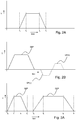
- Fig. 2A illustrates an actuation pulse for actuating an actuator of an inkjet print head for increasing and decreasing a volume of a pressure chamber, thereby generating a pressure wave in a liquid in the pressure chamber, as above described.
- the liquid may also be referred to as ink or fluid marking material, but the liquid may be any other liquid.
- the illustrated actuation pulse has a trapezoid shape, which is a commonly known pulse shape. Still, other shapes of the actuation pulse are contemplated and are within the scope of the present invention.
- the trapezoid pulse starts from an initial voltage, may be 0 volt or any other suitable voltage, with a rise time from time t 0 to time t 1 to a predetermined maximum pulse voltage.
- the maximum pulse voltage is maintained during a dwell time running from time t 1 to time t 2 .
- the voltage drops to the initial value again.
- the actuator is actuated to follow this cycle by increasing the pressure chamber volume during the rise time, maintaining the increased volume during the dwell time and subsequently reducing the pressure chamber volume during the fall time.
- the actual duration of the rise time, dwell time and fall time determine a frequency spectrum of the actuation pulse.
- the frequency spectrum is derivable by performing a Fourier transformation, which is a mathematical method well known in the art and which is therefore not further elucidated herein.
- the pressure chamber has a number of acoustical resonant modes, which are determined inter alia by the dimensions of the pressure chamber and physical properties of a medium, such as the liquid, present in the pressure chamber, wherein such physical properties are viscosity and density, for example. Depending on the frequency spectrum of the actuation pulse, such resonant modes are excited or not. After actuation, i.e. after time t 3 , a residual pressure wave remains in the liquid in the pressure chamber, which residual pressure wave damps over time. The residual pressure wave shape depends strongly on the acoustical resonances in the pressure chamber. While such resonances mainly result from the resonant modes of the pressure chamber, further resonances may occur.
- an air bubble may have become entrapped in the pressure chamber.
- Such air bubble may resonate at a certain frequency, which frequency depends on the size of the air bubble.
- the acoustics including the resonances in the pressure chamber and the shape of the actuation pulse, are adapted to generate a suitable pressure near the orifice such that an amount of liquid is pushed through the orifice, which amount then forms the droplet.
- Fig. 2B illustrates a droplet ejection pulse DEP followed by a first quench pulse QP(a) or a second quench pulse QP(b), which suppress the residual pressure wave in the pressure chamber.
- a first quench pulse QP(a) or a second quench pulse QP(b) which suppress the residual pressure wave in the pressure chamber.
- One of these quench pulses is supplied to prepare the pressure chamber and the liquid contained therein for a next actuation such that the residual pressure wave does not affect the next droplet generation, for example.
- quench pulses are well known in the art.
- the droplet ejection pulse DEP does not include such a quench pulse QP(a) or QP(b).
- the term 'droplet ejection pulse' as used herein only includes the pulse for actually expelling the droplet.
- a disturbance detection pulse formed by the droplet ejection pulse dep as shown in Fig. 2B without the quench pulse QP(a) or QP(b) is deemed to be a same actuation pulse having a same frequency spectrum.
- Fig. 3A illustrates a first embodiment of a droplet ejection pulse DEP and a corresponding disturbance detection pulse DDP.
- the disturbance detection pulse DDP deviates from the droplet ejection pulse not in its shape, but in a value of a number of parameters of the shape.
- the trapezoid pulse shape may be represented by three parameters: duration of the rise time, duration of the dwell time and the duration of the fall time.
- the three values of the three parameters may be (1, 1, 1), meaning that the rise time, dwell time and the fall time have an equal duration. In an embodiment, these values may be actual microseconds, in which case the rise time is 1 microsecond, the dwell time is 1 microsecond and the fall time is 1 microsecond.
- Fig. 3B the corresponding frequency spectrum is shown with a dashed curve. With a maximum at 0 kHz, the amplitude falls gradually to zero at about 500 kHz.
- the residual pressure wave may have the frequency spectrum as shown in Fig. 3C (dashed curve).
- a maximum is present at a frequency of about 150 kHz, which corresponds to a second resonant mode of the pressure chamber.
- a first resonant mode of the pressure chamber is present and derivable from the dashed curve in Fig. 3C at about 70 kHz.
- the amplitude of this first resonant mode is about a fifth of the amplitude at the second resonant mode at about 150 kHz.
- the difference in amplitude is known to be caused by a stronger damping at the first resonant mode than at the second resonant mode.
- any disturbance causing the first resonant mode to be deviated will be more difficult to be identified than a disturbance affecting the second resonant mode.
- common disturbances usually affect the first resonant mode more than the second resonant mode.
- the residual pressure wave resulting from the droplet ejection pulse DEP may not be the best option for readily revealing such common disturbances.
- the disturbance detection pulse DDP has a different set of parameter values. Presuming the pressure chamber with a first resonant mode at about 70 kHz and a second resonant mode at about 150 kHz, wherein common disturbances are best revealed by the amplitude in the residual pressure wave at the first resonant mode of about 70 kHz, the disturbance detection pulse DDP is designed to suppress the second resonant mode at 150 kHz, or at least to amplify the residual pressure wave response at 70 kHz by more strongly exciting the first resonant mode at about 70 kHz.
- Fig. 3B illustrates the corresponding frequency spectrum (solid curve).
- the frequency spectrum of the disturbance detection pulse DDP has a significantly higher amplitude at 0 kHz and falling off to about zero amplitude at about 150 kHz.
- the amplitude is still more than about 60% of the maximum amplitude, while at the second resonant mode the amplitude is about zero.
- Fig. 3C shows the frequency spectrum of the corresponding residual pressure wave (solid curve).
- the second resonant mode has still the highest amplitude.
- the amplitude at about 70 kHz corresponding to the first resonant mode has almost a same amplitude.
- any deviation in the first resonant mode caused by a disturbance is much easier detectable from a residual pressure wave having such a strong signal component from the first resonant mode.
- the disturbance detection pulse DDP as shown in Fig. 3A has a similar pulse shape as the droplet ejection pulse DEP, i.e. a trapezoid shape, with deviating parameter values.
- Such embodiment is very suitable and effective as the drive circuitry for generating the pulse shape may be kept simple and cost-effective.
- a more complex and expensive drive circuitry is available, a more complex and even more effective disturbance detection pulse DDP may be used in the present invention.
- Fig. 4A shows a second and a third embodiment of such a disturbance detection pulse DDP.
- Fig. 4B shows the respective corresponding frequency spectra of the second and third embodiments of Fig. 4A .
- Fig. 4A shows the second embodiment with a solid curve.
- the disturbance detection pulse DDP has been mathematically derived by determining all acoustic resonant modes in the frequency response spectrum of the pressure chamber and equalizing the amplitudes in the frequency spectrum of the residual pressure wave to an equal value, e.g. 1. It is noted that, in an embodiment, one or more resonant modes may be more relevant for detecting disturbances, in which case the amplitudes may be mathematically optimized to different values.
- the second embodiment of the disturbance detection pulse DDP has been derived without imposing further constrains.
- the disturbance detection pulse DDP (unconstrained) has a gradually changing amplitude that becomes negative after about 7 microseconds until about 14 microseconds after its start.
- Its frequency spectrum ( Fig. 4B , solid curve) is also gradually changing and has a broad peak in the frequency range from about 50 kHz to about 100 kHz.
- a noticeable difference with the frequency spectra shown in Fig. 3B is the amplitude at 0 kHz. While the amplitude at 0 kHz was at a maximum for both curves in Fig. 3B , the maximum amplitude is not at a maximum in this second embodiment.
- the third embodiment is illustrated in Fig. 4A as a dotted curve.
- the third embodiment is a simplified embodiment of the second embodiment. While the second embodiment was unconstrained, it is commercially not reasonable to implement the second embodiment. A linearization of the second embodiment simplifies the drive circuitry to a technically and commercially feasible embodiment.
- a between the embossed dots linearly changing amplitude is provided as a third embodiment, herein also referred to as a constrained disturbance detection pulse DDP (constrained).
- DDP constrained disturbance detection pulse
- a difference between the second and the third embodiment is very small. The difference is however more clearly present in Fig. 4B .
- structural elements may be generated by application of three-dimensional (3D) printing techniques. Therefore, any reference to a structural element is intended to encompass any computer executable instructions that instruct a computer to generate such a structural element by three-dimensional printing techniques or similar computer controlled manufacturing techniques. Furthermore, such a reference to a structural element encompasses a computer readable medium carrying such computer executable instructions.
- the terms and phrases used herein are not intended to be limiting; but rather, to provide an understandable description of the invention.
- the terms "a” or “an”, as used herein, are defined as one or more than one.
- the term plurality, as used herein, is defined as two or more than two.
- the term another, as used herein, is defined as at least a second or more.
- the terms including and/or having, as used herein, are defined as comprising (i.e., open language).
- the term coupled, as used herein, is defined as connected, although not necessarily directly.
Landscapes
- Engineering & Computer Science (AREA)
- Quality & Reliability (AREA)
- Particle Formation And Scattering Control In Inkjet Printers (AREA)
- Ink Jet (AREA)
Claims (8)
- Procédé de détection d'une perturbation dans une unité d'éjection d'une tête d'impression à jet d'encre (4a, 4b, 4c, 4d), l'unité d'éjection de la tête d'impression à jet d'encre comprenant- une chambre de pression destinée à contenir une quantité de liquide et étant en communication fluidique avec un orifice de buse (8) ;- un actionneur couplé fonctionnellement à la chambre de pression pour générer une onde de pression dans le liquide dans la chambre de pression pour éjecter une gouttelette du liquide au travers de l'orifice de buse (8) lors de l'application d'une impulsion d'éjection de gouttelette ;le procédé comprenant les étapes dea) détermination d'au moins une fréquence de résonance de la chambre de pression ;b) détermination d'une impulsion de détection de perturbation pour générer une onde de pression dans le liquide dans la chambre de pression en prenant en compte les fréquences de résonance déterminées à l'étape a), dans lequel l'impulsion de détection de perturbation a un spectre de fréquence différent d'un spectre de fréquence de l'impulsion d'éjection de gouttelette ;c) détection d'une onde de pression résiduelle dans le liquide dans la chambre de pression ;d) analyse de l'onde de pression résiduelle détectée à l'étape c) pour déterminer si une perturbation pour l'éjection de gouttelette est présente dans l'unité d'éjection.
- Procédé selon la revendication 1, dans lequel à l'étape a) au moins deux fréquences de résonance sont déterminées, le procédé comprenant en outre
a1) la détermination d'un facteur d'amortissement pour chaque fréquence de résonance déterminée à l'étape a) ;
et dans lequel l'étape b) comprend en outre la prise en compte du facteur d'amortissement respectif pour chaque fréquence de résonance déterminée à l'étape a). - Procédé selon la revendication 2, dans lequel aux étapes a) et a1) une première fréquence de résonance à fort amortissement est déterminée et une seconde fréquence de résonance à faible amortissement est déterminée et dans lequel à l'étape b) le spectre de fréquence de l'impulsion de détection de perturbation est déterminé comme ayant une amplitude plus élevée dans le spectre de fréquence à la première fréquence de résonance qu'à la seconde fréquence de résonance.
- Procédé selon la revendication 1, dans lequel l'impulsion d'éjection de gouttelette a une forme représentée par un ensemble de paramètres prédéterminé et dans lequel l'impulsion de détection de perturbation a une forme similaire représentée par le même ensemble de paramètres prédéterminé ayant des valeurs différentes des valeurs des paramètres pour l'impulsion d'éjection de gouttelette.
- Procédé selon la revendication 1, dans lequel à l'étape a) au moins deux fréquences de résonance sont déterminées, le procédé comprenant en outre
a2) la détermination d'une pertinence de perturbation pour chaque fréquence de résonance déterminée à l'étape a), la pertinence de perturbation représentant la pertinence de la fréquence de résonance pour détecter une perturbation dans l'unité d'éjection ;
et dans lequel l'étape b) comprend en outre la prise en compte de la pertinence de perturbation respective pour chaque fréquence de résonance déterminée à l'étape a). - Procédé selon la revendication 5, dans lequel aux étapes a) et a2) une première fréquence de résonance à faible pertinence de perturbation est déterminée et une seconde fréquence de résonance à pertinence de perturbation élevée est déterminée et dans lequel à l'étape b) le spectre de fréquence de l'impulsion de détection de perturbation est déterminé comme ayant une amplitude plus élevée dans le spectre de fréquence à la seconde fréquence de résonance qu'à la première fréquence de résonance.
- Procédé selon la revendication 1, dans lequel l'étape a) comprend la détermination d'un spectre de réponse en fréquence de la chambre de pression et dans lequel l'étape b) comprend la prise en compte du spectre de réponse en fréquence pour déterminer le signal de détection de perturbation.
- Imprimante à jet d'encre comprenant une tête d'impression à jet d'encre (4a, 4b, 4c, 4d) et une unité de commande (34) couplée fonctionnellement à la tête d'impression à jet d'encre pour commander le fonctionnement de la tête d'impression à jet d'encre, la tête d'impression à jet d'encre comprenant une unité d'éjection, dans laquelle l'unité d'éjection comprend :- une chambre de pression destinée à contenir une quantité de liquide et étant en communication fluidique avec un orifice de buse (8) ;- un actionneur couplé fonctionnellement à la chambre de pression pour générer une onde de pression dans le liquide dans la chambre de pression pour éjecter une gouttelette du liquide au travers de l'orifice de buse (8) lors de l'application d'une impulsion d'éjection de gouttelette ;dans laquelle l'unité de commande est configurée pour fournir l'impulsion d'éjection de gouttelette à la tête d'impression à jet d'encre pour commander la tête d'impression à jet d'encre pour expulser une gouttelette de liquide au travers de l'orifice de buse (8) ; et
dans laquelle l'unité de commande est configurée pour fournir une impulsion de détection de perturbation, puis pour détecter une onde de pression résiduelle dans la chambre de pression et pour analyser l'onde de pression résiduelle pour déterminer si une perturbation est présente dans l'unité d'éjection de la tête d'impression à jet d'encre, l'impulsion de détection de perturbation étant déterminée en prenant en compte au moins une fréquence de résonance de la chambre de pression et ayant un spectre de fréquence différent d'un spectre de fréquence de l'impulsion d'éjection de gouttelette.
Applications Claiming Priority (2)
| Application Number | Priority Date | Filing Date | Title |
|---|---|---|---|
| EP16157271 | 2016-02-25 | ||
| PCT/EP2017/053463 WO2017144335A1 (fr) | 2016-02-25 | 2017-02-16 | Procédé servant à détecter une perturbation dans une éjection de gouttelettes d'une tête d'impression à jet d'encre |
Publications (2)
| Publication Number | Publication Date |
|---|---|
| EP3419829A1 EP3419829A1 (fr) | 2019-01-02 |
| EP3419829B1 true EP3419829B1 (fr) | 2020-04-08 |
Family
ID=55451033
Family Applications (1)
| Application Number | Title | Priority Date | Filing Date |
|---|---|---|---|
| EP17705614.0A Active EP3419829B1 (fr) | 2016-02-25 | 2017-02-16 | Procédé permettant de détecter une perturbation dans l'éjection des gouttelettes d'une tête d'impression à jet d'encre |
Country Status (4)
| Country | Link |
|---|---|
| US (1) | US10471710B2 (fr) |
| EP (1) | EP3419829B1 (fr) |
| JP (1) | JP6975159B2 (fr) |
| WO (1) | WO2017144335A1 (fr) |
Families Citing this family (3)
| Publication number | Priority date | Publication date | Assignee | Title |
|---|---|---|---|---|
| EP3784495B1 (fr) | 2018-04-23 | 2024-03-27 | Canon Production Printing Holding B.V. | Procédé de détection de défaillance de buse rapide |
| EP3670191A1 (fr) * | 2018-12-17 | 2020-06-24 | Canon Production Printing Holding B.V. | Circuit et procédé de détection et de contrôle de changements de viscoélasticité dans une tête d'impression à jet d'encre |
| EP4417427B1 (fr) | 2023-02-14 | 2025-10-01 | Haute école d'ingénierie et d'architecture Fribourg | Système et procédé pour système à jet d'encre |
Family Cites Families (7)
| Publication number | Priority date | Publication date | Assignee | Title |
|---|---|---|---|---|
| US7232199B2 (en) * | 2003-03-28 | 2007-06-19 | Seiko Epson Corporation | Droplet ejection apparatus and method of detecting and judging ejection failure in droplet ejection heads |
| JP4538789B2 (ja) * | 2004-07-07 | 2010-09-08 | 富士フイルム株式会社 | 液吐出装置及び吐出異常検出方法 |
| JP4845879B2 (ja) * | 2005-03-18 | 2011-12-28 | 日本碍子株式会社 | 圧電素子の検査方法、検査装置及び分極処理方法 |
| JP2007076326A (ja) * | 2005-09-16 | 2007-03-29 | Fujifilm Corp | 気泡検出方法及び液体吐出装置並びに画像形成装置 |
| EP2328756B1 (fr) * | 2008-08-27 | 2014-05-07 | OCE-Technologies B.V. | Procédé de détection d'un état de fonctionnement d'une chambre fluide d'une tête d'impression à jet d'encre |
| KR20110092110A (ko) * | 2010-02-08 | 2011-08-17 | 삼성전기주식회사 | 잉크젯 헤드의 모니터링 장치 |
| WO2012175593A1 (fr) * | 2011-06-24 | 2012-12-27 | Oce-Technologies B.V. | Tête d'impression à jet d'encre |
-
2017
- 2017-02-16 WO PCT/EP2017/053463 patent/WO2017144335A1/fr not_active Ceased
- 2017-02-16 JP JP2018542721A patent/JP6975159B2/ja active Active
- 2017-02-16 EP EP17705614.0A patent/EP3419829B1/fr active Active
-
2018
- 2018-08-24 US US16/111,937 patent/US10471710B2/en active Active
Non-Patent Citations (1)
| Title |
|---|
| None * |
Also Published As
| Publication number | Publication date |
|---|---|
| WO2017144335A1 (fr) | 2017-08-31 |
| JP2019511394A (ja) | 2019-04-25 |
| US20180361735A1 (en) | 2018-12-20 |
| JP6975159B2 (ja) | 2021-12-01 |
| US10471710B2 (en) | 2019-11-12 |
| EP3419829A1 (fr) | 2019-01-02 |
Similar Documents
| Publication | Publication Date | Title |
|---|---|---|
| EP3212404B1 (fr) | Procédé pour détecter un état de fonctionnement d'une buse de tête d'impression à jet d'encre | |
| US10144215B2 (en) | Method for detecting an operating status of an inkjet nozzle | |
| EP3222422B1 (fr) | Procédé de fonctionnement d'une tête d'impression à jet d'encre et ensemble de tête d'impression à jet d'encre | |
| JP4538789B2 (ja) | 液吐出装置及び吐出異常検出方法 | |
| JP6409262B2 (ja) | インクジェット装置及びインクジェットシステム | |
| US10471710B2 (en) | Method for detecting disturbance in droplet ejection of an inkjet print head | |
| JP2017517408A (ja) | フラットベッドプリンタアセンブリ | |
| US20150210073A1 (en) | Liquid ejecting apparatus and method of controlling liquid ejecting apparatus | |
| JP2008023793A (ja) | 液体吐出ヘッド及び画像形成装置 | |
| EP3235647A1 (fr) | Appareil d'éjection de liquide, système à jet d'encre et procédé de flushing | |
| JP6754201B2 (ja) | 印刷装置および印刷用コンピュータプログラム | |
| WO2014124836A1 (fr) | Procédé d'établissement d'un intervalle de temps de maintenance pour un dispositif d'impression | |
| US8882239B2 (en) | Method for determining maintenance unit performance | |
| JP6409261B2 (ja) | 装置及びシステム | |
| US9701109B2 (en) | Liquid discharging apparatus and control method of liquid discharging apparatus | |
| EP1609600B1 (fr) | Système à jet d'encre, procédé de réalisation de celle-ci et utilisation dudit système | |
| EP3421242B1 (fr) | Ensemble tête d'impression à jet d'encre et procédé de fabrication d'une telle tête d'impression à jet d'encre | |
| EP2662217A1 (fr) | Procédé de fonctionnement d'une tête d'impression à jet d'encre | |
| EP2855155A1 (fr) | Procédé de fonctionnement d'un dispositif à jet d'encre | |
| JP2020001332A (ja) | 液体噴射ヘッド、液体噴射記録装置および液体噴射ヘッドの駆動方法 | |
| JP2011224834A (ja) | 画像記録装置 |
Legal Events
| Date | Code | Title | Description |
|---|---|---|---|
| STAA | Information on the status of an ep patent application or granted ep patent |
Free format text: STATUS: UNKNOWN |
|
| STAA | Information on the status of an ep patent application or granted ep patent |
Free format text: STATUS: THE INTERNATIONAL PUBLICATION HAS BEEN MADE |
|
| PUAI | Public reference made under article 153(3) epc to a published international application that has entered the european phase |
Free format text: ORIGINAL CODE: 0009012 |
|
| STAA | Information on the status of an ep patent application or granted ep patent |
Free format text: STATUS: REQUEST FOR EXAMINATION WAS MADE |
|
| 17P | Request for examination filed |
Effective date: 20180925 |
|
| AK | Designated contracting states |
Kind code of ref document: A1 Designated state(s): AL AT BE BG CH CY CZ DE DK EE ES FI FR GB GR HR HU IE IS IT LI LT LU LV MC MK MT NL NO PL PT RO RS SE SI SK SM TR |
|
| AX | Request for extension of the european patent |
Extension state: BA ME |
|
| DAV | Request for validation of the european patent (deleted) | ||
| DAX | Request for extension of the european patent (deleted) | ||
| GRAP | Despatch of communication of intention to grant a patent |
Free format text: ORIGINAL CODE: EPIDOSNIGR1 |
|
| STAA | Information on the status of an ep patent application or granted ep patent |
Free format text: STATUS: GRANT OF PATENT IS INTENDED |
|
| INTG | Intention to grant announced |
Effective date: 20190925 |
|
| GRAS | Grant fee paid |
Free format text: ORIGINAL CODE: EPIDOSNIGR3 |
|
| GRAA | (expected) grant |
Free format text: ORIGINAL CODE: 0009210 |
|
| STAA | Information on the status of an ep patent application or granted ep patent |
Free format text: STATUS: THE PATENT HAS BEEN GRANTED |
|
| RAP1 | Party data changed (applicant data changed or rights of an application transferred) |
Owner name: CANON PRODUCTION PRINTING HOLDING B.V. |
|
| AK | Designated contracting states |
Kind code of ref document: B1 Designated state(s): AL AT BE BG CH CY CZ DE DK EE ES FI FR GB GR HR HU IE IS IT LI LT LU LV MC MK MT NL NO PL PT RO RS SE SI SK SM TR |
|
| REG | Reference to a national code |
Ref country code: AT Ref legal event code: REF Ref document number: 1253837 Country of ref document: AT Kind code of ref document: T Effective date: 20200415 Ref country code: CH Ref legal event code: EP |
|
| REG | Reference to a national code |
Ref country code: DE Ref legal event code: R096 Ref document number: 602017014377 Country of ref document: DE |
|
| REG | Reference to a national code |
Ref country code: IE Ref legal event code: FG4D |
|
| REG | Reference to a national code |
Ref country code: NL Ref legal event code: FP |
|
| REG | Reference to a national code |
Ref country code: LT Ref legal event code: MG4D |
|
| PG25 | Lapsed in a contracting state [announced via postgrant information from national office to epo] |
Ref country code: FI Free format text: LAPSE BECAUSE OF FAILURE TO SUBMIT A TRANSLATION OF THE DESCRIPTION OR TO PAY THE FEE WITHIN THE PRESCRIBED TIME-LIMIT Effective date: 20200408 Ref country code: SE Free format text: LAPSE BECAUSE OF FAILURE TO SUBMIT A TRANSLATION OF THE DESCRIPTION OR TO PAY THE FEE WITHIN THE PRESCRIBED TIME-LIMIT Effective date: 20200408 Ref country code: PT Free format text: LAPSE BECAUSE OF FAILURE TO SUBMIT A TRANSLATION OF THE DESCRIPTION OR TO PAY THE FEE WITHIN THE PRESCRIBED TIME-LIMIT Effective date: 20200817 Ref country code: LT Free format text: LAPSE BECAUSE OF FAILURE TO SUBMIT A TRANSLATION OF THE DESCRIPTION OR TO PAY THE FEE WITHIN THE PRESCRIBED TIME-LIMIT Effective date: 20200408 Ref country code: NO Free format text: LAPSE BECAUSE OF FAILURE TO SUBMIT A TRANSLATION OF THE DESCRIPTION OR TO PAY THE FEE WITHIN THE PRESCRIBED TIME-LIMIT Effective date: 20200708 Ref country code: IS Free format text: LAPSE BECAUSE OF FAILURE TO SUBMIT A TRANSLATION OF THE DESCRIPTION OR TO PAY THE FEE WITHIN THE PRESCRIBED TIME-LIMIT Effective date: 20200808 Ref country code: GR Free format text: LAPSE BECAUSE OF FAILURE TO SUBMIT A TRANSLATION OF THE DESCRIPTION OR TO PAY THE FEE WITHIN THE PRESCRIBED TIME-LIMIT Effective date: 20200709 |
|
| REG | Reference to a national code |
Ref country code: AT Ref legal event code: MK05 Ref document number: 1253837 Country of ref document: AT Kind code of ref document: T Effective date: 20200408 |
|
| RAP2 | Party data changed (patent owner data changed or rights of a patent transferred) |
Owner name: CANON PRODUCTION PRINTING HOLDING B.V. |
|
| PG25 | Lapsed in a contracting state [announced via postgrant information from national office to epo] |
Ref country code: BG Free format text: LAPSE BECAUSE OF FAILURE TO SUBMIT A TRANSLATION OF THE DESCRIPTION OR TO PAY THE FEE WITHIN THE PRESCRIBED TIME-LIMIT Effective date: 20200708 Ref country code: RS Free format text: LAPSE BECAUSE OF FAILURE TO SUBMIT A TRANSLATION OF THE DESCRIPTION OR TO PAY THE FEE WITHIN THE PRESCRIBED TIME-LIMIT Effective date: 20200408 Ref country code: LV Free format text: LAPSE BECAUSE OF FAILURE TO SUBMIT A TRANSLATION OF THE DESCRIPTION OR TO PAY THE FEE WITHIN THE PRESCRIBED TIME-LIMIT Effective date: 20200408 Ref country code: HR Free format text: LAPSE BECAUSE OF FAILURE TO SUBMIT A TRANSLATION OF THE DESCRIPTION OR TO PAY THE FEE WITHIN THE PRESCRIBED TIME-LIMIT Effective date: 20200408 |
|
| PG25 | Lapsed in a contracting state [announced via postgrant information from national office to epo] |
Ref country code: AL Free format text: LAPSE BECAUSE OF FAILURE TO SUBMIT A TRANSLATION OF THE DESCRIPTION OR TO PAY THE FEE WITHIN THE PRESCRIBED TIME-LIMIT Effective date: 20200408 |
|
| REG | Reference to a national code |
Ref country code: DE Ref legal event code: R097 Ref document number: 602017014377 Country of ref document: DE |
|
| PG25 | Lapsed in a contracting state [announced via postgrant information from national office to epo] |
Ref country code: IT Free format text: LAPSE BECAUSE OF FAILURE TO SUBMIT A TRANSLATION OF THE DESCRIPTION OR TO PAY THE FEE WITHIN THE PRESCRIBED TIME-LIMIT Effective date: 20200408 Ref country code: DK Free format text: LAPSE BECAUSE OF FAILURE TO SUBMIT A TRANSLATION OF THE DESCRIPTION OR TO PAY THE FEE WITHIN THE PRESCRIBED TIME-LIMIT Effective date: 20200408 Ref country code: EE Free format text: LAPSE BECAUSE OF FAILURE TO SUBMIT A TRANSLATION OF THE DESCRIPTION OR TO PAY THE FEE WITHIN THE PRESCRIBED TIME-LIMIT Effective date: 20200408 Ref country code: SM Free format text: LAPSE BECAUSE OF FAILURE TO SUBMIT A TRANSLATION OF THE DESCRIPTION OR TO PAY THE FEE WITHIN THE PRESCRIBED TIME-LIMIT Effective date: 20200408 Ref country code: CZ Free format text: LAPSE BECAUSE OF FAILURE TO SUBMIT A TRANSLATION OF THE DESCRIPTION OR TO PAY THE FEE WITHIN THE PRESCRIBED TIME-LIMIT Effective date: 20200408 Ref country code: RO Free format text: LAPSE BECAUSE OF FAILURE TO SUBMIT A TRANSLATION OF THE DESCRIPTION OR TO PAY THE FEE WITHIN THE PRESCRIBED TIME-LIMIT Effective date: 20200408 Ref country code: ES Free format text: LAPSE BECAUSE OF FAILURE TO SUBMIT A TRANSLATION OF THE DESCRIPTION OR TO PAY THE FEE WITHIN THE PRESCRIBED TIME-LIMIT Effective date: 20200408 Ref country code: AT Free format text: LAPSE BECAUSE OF FAILURE TO SUBMIT A TRANSLATION OF THE DESCRIPTION OR TO PAY THE FEE WITHIN THE PRESCRIBED TIME-LIMIT Effective date: 20200408 |
|
| PLBE | No opposition filed within time limit |
Free format text: ORIGINAL CODE: 0009261 |
|
| STAA | Information on the status of an ep patent application or granted ep patent |
Free format text: STATUS: NO OPPOSITION FILED WITHIN TIME LIMIT |
|
| PG25 | Lapsed in a contracting state [announced via postgrant information from national office to epo] |
Ref country code: PL Free format text: LAPSE BECAUSE OF FAILURE TO SUBMIT A TRANSLATION OF THE DESCRIPTION OR TO PAY THE FEE WITHIN THE PRESCRIBED TIME-LIMIT Effective date: 20200408 Ref country code: SK Free format text: LAPSE BECAUSE OF FAILURE TO SUBMIT A TRANSLATION OF THE DESCRIPTION OR TO PAY THE FEE WITHIN THE PRESCRIBED TIME-LIMIT Effective date: 20200408 |
|
| 26N | No opposition filed |
Effective date: 20210112 |
|
| PG25 | Lapsed in a contracting state [announced via postgrant information from national office to epo] |
Ref country code: SI Free format text: LAPSE BECAUSE OF FAILURE TO SUBMIT A TRANSLATION OF THE DESCRIPTION OR TO PAY THE FEE WITHIN THE PRESCRIBED TIME-LIMIT Effective date: 20200408 |
|
| PG25 | Lapsed in a contracting state [announced via postgrant information from national office to epo] |
Ref country code: MC Free format text: LAPSE BECAUSE OF FAILURE TO SUBMIT A TRANSLATION OF THE DESCRIPTION OR TO PAY THE FEE WITHIN THE PRESCRIBED TIME-LIMIT Effective date: 20200408 |
|
| REG | Reference to a national code |
Ref country code: BE Ref legal event code: MM Effective date: 20210228 |
|
| PG25 | Lapsed in a contracting state [announced via postgrant information from national office to epo] |
Ref country code: CH Free format text: LAPSE BECAUSE OF NON-PAYMENT OF DUE FEES Effective date: 20210228 Ref country code: LU Free format text: LAPSE BECAUSE OF NON-PAYMENT OF DUE FEES Effective date: 20210216 Ref country code: LI Free format text: LAPSE BECAUSE OF NON-PAYMENT OF DUE FEES Effective date: 20210228 |
|
| PG25 | Lapsed in a contracting state [announced via postgrant information from national office to epo] |
Ref country code: IE Free format text: LAPSE BECAUSE OF NON-PAYMENT OF DUE FEES Effective date: 20210216 |
|
| PG25 | Lapsed in a contracting state [announced via postgrant information from national office to epo] |
Ref country code: BE Free format text: LAPSE BECAUSE OF NON-PAYMENT OF DUE FEES Effective date: 20210228 |
|
| PG25 | Lapsed in a contracting state [announced via postgrant information from national office to epo] |
Ref country code: CY Free format text: LAPSE BECAUSE OF FAILURE TO SUBMIT A TRANSLATION OF THE DESCRIPTION OR TO PAY THE FEE WITHIN THE PRESCRIBED TIME-LIMIT Effective date: 20200408 |
|
| PG25 | Lapsed in a contracting state [announced via postgrant information from national office to epo] |
Ref country code: HU Free format text: LAPSE BECAUSE OF FAILURE TO SUBMIT A TRANSLATION OF THE DESCRIPTION OR TO PAY THE FEE WITHIN THE PRESCRIBED TIME-LIMIT; INVALID AB INITIO Effective date: 20170216 |
|
| PG25 | Lapsed in a contracting state [announced via postgrant information from national office to epo] |
Ref country code: MK Free format text: LAPSE BECAUSE OF FAILURE TO SUBMIT A TRANSLATION OF THE DESCRIPTION OR TO PAY THE FEE WITHIN THE PRESCRIBED TIME-LIMIT Effective date: 20200408 |
|
| PG25 | Lapsed in a contracting state [announced via postgrant information from national office to epo] |
Ref country code: MT Free format text: LAPSE BECAUSE OF FAILURE TO SUBMIT A TRANSLATION OF THE DESCRIPTION OR TO PAY THE FEE WITHIN THE PRESCRIBED TIME-LIMIT Effective date: 20200408 |
|
| PGFP | Annual fee paid to national office [announced via postgrant information from national office to epo] |
Ref country code: NL Payment date: 20250116 Year of fee payment: 9 |
|
| PGFP | Annual fee paid to national office [announced via postgrant information from national office to epo] |
Ref country code: DE Payment date: 20250218 Year of fee payment: 9 |
|
| PGFP | Annual fee paid to national office [announced via postgrant information from national office to epo] |
Ref country code: FR Payment date: 20250221 Year of fee payment: 9 |
|
| PGFP | Annual fee paid to national office [announced via postgrant information from national office to epo] |
Ref country code: GB Payment date: 20250220 Year of fee payment: 9 |
|
| PG25 | Lapsed in a contracting state [announced via postgrant information from national office to epo] |
Ref country code: TR Free format text: LAPSE BECAUSE OF FAILURE TO SUBMIT A TRANSLATION OF THE DESCRIPTION OR TO PAY THE FEE WITHIN THE PRESCRIBED TIME-LIMIT Effective date: 20200408 |