EP3419340B1 - Systeminformationssignalempfangsverfahren, benutzergerät, systeminformationssignalübertragungsverfahren und basisstation - Google Patents
Systeminformationssignalempfangsverfahren, benutzergerät, systeminformationssignalübertragungsverfahren und basisstation Download PDFInfo
- Publication number
- EP3419340B1 EP3419340B1 EP17763500.0A EP17763500A EP3419340B1 EP 3419340 B1 EP3419340 B1 EP 3419340B1 EP 17763500 A EP17763500 A EP 17763500A EP 3419340 B1 EP3419340 B1 EP 3419340B1
- Authority
- EP
- European Patent Office
- Prior art keywords
- prach
- transmission
- random access
- index
- rar
- Prior art date
- Legal status (The legal status is an assumption and is not a legal conclusion. Google has not performed a legal analysis and makes no representation as to the accuracy of the status listed.)
- Active
Links
- 238000000034 method Methods 0.000 title claims description 123
- 230000004044 response Effects 0.000 claims description 16
- 230000015654 memory Effects 0.000 claims description 12
- 230000005540 biological transmission Effects 0.000 description 280
- 238000004891 communication Methods 0.000 description 66
- 238000005259 measurement Methods 0.000 description 23
- 238000005516 engineering process Methods 0.000 description 21
- 238000001514 detection method Methods 0.000 description 16
- 230000006870 function Effects 0.000 description 15
- 238000013459 approach Methods 0.000 description 11
- 230000008569 process Effects 0.000 description 11
- 125000004122 cyclic group Chemical group 0.000 description 8
- 230000008054 signal transmission Effects 0.000 description 8
- 230000011664 signaling Effects 0.000 description 8
- 230000002776 aggregation Effects 0.000 description 7
- 238000004220 aggregation Methods 0.000 description 7
- 238000013507 mapping Methods 0.000 description 7
- 238000013468 resource allocation Methods 0.000 description 6
- 238000010408 sweeping Methods 0.000 description 6
- 238000012545 processing Methods 0.000 description 5
- 238000010295 mobile communication Methods 0.000 description 4
- 238000012546 transfer Methods 0.000 description 4
- 241001522296 Erithacus rubecula Species 0.000 description 3
- 101100533725 Mus musculus Smr3a gene Proteins 0.000 description 3
- 239000000872 buffer Substances 0.000 description 3
- 238000006243 chemical reaction Methods 0.000 description 3
- 238000000794 confocal Raman spectroscopy Methods 0.000 description 3
- 238000011500 cytoreductive surgery Methods 0.000 description 3
- 238000011161 development Methods 0.000 description 3
- 238000010586 diagram Methods 0.000 description 3
- 230000000694 effects Effects 0.000 description 3
- 230000007246 mechanism Effects 0.000 description 3
- 239000002699 waste material Substances 0.000 description 3
- 101001061911 Homo sapiens Ras-related protein Rab-40A Proteins 0.000 description 2
- 102100029553 Ras-related protein Rab-40A Human genes 0.000 description 2
- 230000015556 catabolic process Effects 0.000 description 2
- 238000005352 clarification Methods 0.000 description 2
- 238000013461 design Methods 0.000 description 2
- VJYFKVYYMZPMAB-UHFFFAOYSA-N ethoprophos Chemical compound CCCSP(=O)(OCC)SCCC VJYFKVYYMZPMAB-UHFFFAOYSA-N 0.000 description 2
- 239000011159 matrix material Substances 0.000 description 2
- 230000001960 triggered effect Effects 0.000 description 2
- 108700026140 MAC combination Proteins 0.000 description 1
- 101100274486 Mus musculus Cited2 gene Proteins 0.000 description 1
- 101150071746 Pbsn gene Proteins 0.000 description 1
- 241000700159 Rattus Species 0.000 description 1
- 101150096622 Smr2 gene Proteins 0.000 description 1
- 230000004931 aggregating effect Effects 0.000 description 1
- 238000003491 array Methods 0.000 description 1
- 230000003190 augmentative effect Effects 0.000 description 1
- 230000008901 benefit Effects 0.000 description 1
- 230000003139 buffering effect Effects 0.000 description 1
- 238000004364 calculation method Methods 0.000 description 1
- 230000001413 cellular effect Effects 0.000 description 1
- 230000008859 change Effects 0.000 description 1
- 230000001149 cognitive effect Effects 0.000 description 1
- 239000002131 composite material Substances 0.000 description 1
- 238000006731 degradation reaction Methods 0.000 description 1
- 230000001934 delay Effects 0.000 description 1
- 230000001419 dependent effect Effects 0.000 description 1
- 230000009977 dual effect Effects 0.000 description 1
- 230000006872 improvement Effects 0.000 description 1
- 230000007774 longterm Effects 0.000 description 1
- 238000004519 manufacturing process Methods 0.000 description 1
- 230000000873 masking effect Effects 0.000 description 1
- 238000012544 monitoring process Methods 0.000 description 1
- 230000003287 optical effect Effects 0.000 description 1
- 230000000737 periodic effect Effects 0.000 description 1
- 230000009467 reduction Effects 0.000 description 1
- 230000004043 responsiveness Effects 0.000 description 1
- 230000002441 reversible effect Effects 0.000 description 1
- 238000005070 sampling Methods 0.000 description 1
- 238000010187 selection method Methods 0.000 description 1
- 239000004984 smart glass Substances 0.000 description 1
- 230000001360 synchronised effect Effects 0.000 description 1
- 230000008685 targeting Effects 0.000 description 1
- 238000012360 testing method Methods 0.000 description 1
- 238000004929 transmission Raman spectroscopy Methods 0.000 description 1
- XLYOFNOQVPJJNP-UHFFFAOYSA-N water Substances O XLYOFNOQVPJJNP-UHFFFAOYSA-N 0.000 description 1
Images


Classifications
-
- H—ELECTRICITY
- H04—ELECTRIC COMMUNICATION TECHNIQUE
- H04W—WIRELESS COMMUNICATION NETWORKS
- H04W48/00—Access restriction; Network selection; Access point selection
- H04W48/08—Access restriction or access information delivery, e.g. discovery data delivery
- H04W48/14—Access restriction or access information delivery, e.g. discovery data delivery using user query or user detection
-
- H—ELECTRICITY
- H04—ELECTRIC COMMUNICATION TECHNIQUE
- H04W—WIRELESS COMMUNICATION NETWORKS
- H04W74/00—Wireless channel access, e.g. scheduled or random access
- H04W74/08—Non-scheduled or contention based access, e.g. random access, ALOHA, CSMA [Carrier Sense Multiple Access]
- H04W74/0833—Non-scheduled or contention based access, e.g. random access, ALOHA, CSMA [Carrier Sense Multiple Access] using a random access procedure
- H04W74/0841—Non-scheduled or contention based access, e.g. random access, ALOHA, CSMA [Carrier Sense Multiple Access] using a random access procedure with collision treatment
- H04W74/085—Non-scheduled or contention based access, e.g. random access, ALOHA, CSMA [Carrier Sense Multiple Access] using a random access procedure with collision treatment collision avoidance
-
- H—ELECTRICITY
- H04—ELECTRIC COMMUNICATION TECHNIQUE
- H04W—WIRELESS COMMUNICATION NETWORKS
- H04W48/00—Access restriction; Network selection; Access point selection
- H04W48/08—Access restriction or access information delivery, e.g. discovery data delivery
-
- H—ELECTRICITY
- H04—ELECTRIC COMMUNICATION TECHNIQUE
- H04W—WIRELESS COMMUNICATION NETWORKS
- H04W48/00—Access restriction; Network selection; Access point selection
- H04W48/08—Access restriction or access information delivery, e.g. discovery data delivery
- H04W48/10—Access restriction or access information delivery, e.g. discovery data delivery using broadcasted information
-
- H—ELECTRICITY
- H04—ELECTRIC COMMUNICATION TECHNIQUE
- H04W—WIRELESS COMMUNICATION NETWORKS
- H04W56/00—Synchronisation arrangements
- H04W56/001—Synchronization between nodes
-
- H—ELECTRICITY
- H04—ELECTRIC COMMUNICATION TECHNIQUE
- H04W—WIRELESS COMMUNICATION NETWORKS
- H04W56/00—Synchronisation arrangements
- H04W56/001—Synchronization between nodes
- H04W56/0015—Synchronization between nodes one node acting as a reference for the others
-
- H—ELECTRICITY
- H04—ELECTRIC COMMUNICATION TECHNIQUE
- H04W—WIRELESS COMMUNICATION NETWORKS
- H04W72/00—Local resource management
- H04W72/04—Wireless resource allocation
- H04W72/044—Wireless resource allocation based on the type of the allocated resource
- H04W72/0446—Resources in time domain, e.g. slots or frames
-
- H—ELECTRICITY
- H04—ELECTRIC COMMUNICATION TECHNIQUE
- H04W—WIRELESS COMMUNICATION NETWORKS
- H04W72/00—Local resource management
- H04W72/04—Wireless resource allocation
- H04W72/044—Wireless resource allocation based on the type of the allocated resource
- H04W72/0453—Resources in frequency domain, e.g. a carrier in FDMA
-
- H—ELECTRICITY
- H04—ELECTRIC COMMUNICATION TECHNIQUE
- H04W—WIRELESS COMMUNICATION NETWORKS
- H04W72/00—Local resource management
- H04W72/20—Control channels or signalling for resource management
- H04W72/23—Control channels or signalling for resource management in the downlink direction of a wireless link, i.e. towards a terminal
-
- H—ELECTRICITY
- H04—ELECTRIC COMMUNICATION TECHNIQUE
- H04W—WIRELESS COMMUNICATION NETWORKS
- H04W72/00—Local resource management
- H04W72/30—Resource management for broadcast services
-
- H—ELECTRICITY
- H04—ELECTRIC COMMUNICATION TECHNIQUE
- H04W—WIRELESS COMMUNICATION NETWORKS
- H04W74/00—Wireless channel access, e.g. scheduled or random access
- H04W74/002—Transmission of channel access control information
- H04W74/006—Transmission of channel access control information in the downlink, i.e. towards the terminal
-
- H—ELECTRICITY
- H04—ELECTRIC COMMUNICATION TECHNIQUE
- H04W—WIRELESS COMMUNICATION NETWORKS
- H04W74/00—Wireless channel access, e.g. scheduled or random access
- H04W74/002—Transmission of channel access control information
- H04W74/008—Transmission of channel access control information with additional processing of random access related information at receiving side
-
- H—ELECTRICITY
- H04—ELECTRIC COMMUNICATION TECHNIQUE
- H04W—WIRELESS COMMUNICATION NETWORKS
- H04W74/00—Wireless channel access, e.g. scheduled or random access
- H04W74/08—Non-scheduled or contention based access, e.g. random access, ALOHA, CSMA [Carrier Sense Multiple Access]
- H04W74/0833—Non-scheduled or contention based access, e.g. random access, ALOHA, CSMA [Carrier Sense Multiple Access] using a random access procedure
-
- H—ELECTRICITY
- H04—ELECTRIC COMMUNICATION TECHNIQUE
- H04W—WIRELESS COMMUNICATION NETWORKS
- H04W48/00—Access restriction; Network selection; Access point selection
- H04W48/08—Access restriction or access information delivery, e.g. discovery data delivery
- H04W48/12—Access restriction or access information delivery, e.g. discovery data delivery using downlink control channel
-
- H—ELECTRICITY
- H04—ELECTRIC COMMUNICATION TECHNIQUE
- H04W—WIRELESS COMMUNICATION NETWORKS
- H04W74/00—Wireless channel access, e.g. scheduled or random access
- H04W74/08—Non-scheduled or contention based access, e.g. random access, ALOHA, CSMA [Carrier Sense Multiple Access]
Definitions
- the present invention relates to a wireless communication system, and more particularly, to methods and devices for transmitting/receiving system information.
- M2M machine-to-machine
- BS base station
- a general wireless communication system performs data transmission/reception through one downlink (DL) band and through one uplink (UL) band corresponding to the DL band (in case of a frequency division duplex (FDD) mode), or divides a prescribed radio frame into a UL time unit and a DL time unit in the time domain and then performs data transmission/reception through the UL/DL time unit (in case of a time division duplex (TDD) mode).
- a base station (BS) and a user equipment (UE) transmit and receive data and/or control information scheduled on a prescribed time unit basis, e.g. on a subframe basis.
- the data is transmitted and received through a data region configured in a UL/DL subframe and the control information is transmitted and received through a control region configured in the UL/DL subframe.
- various physical channels carrying radio signals are formed in the UL/DL subframe.
- carrier aggregation technology serves to use a wider UL/DL bandwidth by aggregating a plurality of UL/DL frequency blocks in order to use a broader frequency band so that more signals relative to signals when a single carrier is used can be simultaneously processed.
- a communication environment has evolved into increasing density of nodes accessible by a user at the periphery of the nodes.
- a node refers to a fixed point capable of transmitting/receiving a radio signal to/from the UE through one or more antennas.
- a communication system including high-density nodes may provide a better communication service to the UE through cooperation between the nodes.
- eMBB enhanced mobile broadband
- RAT legacy radio access technology
- massive machine type communication for providing various services at any time and anywhere by connecting a plurality of devices and objects to each other is one main issue to be considered in next generation communication.
- next generation radio access technology has been discussed by taking into consideration eMBB communication, mMTC, ultra-reliable and low-latency communication (URLLC), and the like.
- the number of user equipments (UEs) to which a BS should provide a service in a prescribed resource region increases and the amount of data and control information that the BS should transmit to the UEs increases. Since the amount of resources available to the BS for communication with the UE(s) is limited, a new method in which the BS efficiently receives/transmits uplink/downlink data and/or uplink/downlink control information using the limited radio resources is needed.
- uplink/downlink signals can be efficiently transmitted/received. Therefore, overall throughput of a radio communication system can be improved.
- delay/latency occurring during communication between a user equipment and a base station may be reduced.
- signals can be transmitted/received in the system supporting new radio access technologies.
- CDMA code division multiple access
- FDMA frequency division multiple access
- TDMA time division multiple access
- OFDMA orthogonal frequency division multiple access
- SC-FDMA single carrier frequency division multiple access
- MC-FDMA multicarrier frequency division multiple access
- CDMA may be embodied through radio technology such as universal terrestrial radio access (UTRA) or CDMA2000.
- TDMA may be embodied through radio technology such as global system for mobile communications (GSM), general packet radio service (GPRS), or enhanced data rates for GSM evolution (EDGE).
- GSM global system for mobile communications
- GPRS general packet radio service
- EDGE enhanced data rates for GSM evolution
- OFDMA may be embodied through radio technology such as institute of electrical and electronics engineers (IEEE) 802.11 (Wi-Fi), IEEE 802.16 (WiMAX), IEEE 802.20, or evolved UTRA (E-UTRA).
- UTRA is a part of a universal mobile telecommunications system (UMTS).
- 3rd generation partnership project (3GPP) long term evolution (LTE) is a part of evolved UMTS (E-UMTS) using E-UTRA.
- 3GPP LTE employs OFDMA in DL and SC-FDMA in UL.
- LTE-advanced (LTE-A) is an evolved version of 3GPP LTE. For convenience of description, it is assumed that the present invention is applied to 3GPP LTE/LTE-A.
- the present invention is applicable to contention based communication such as Wi-Fi as well as non-contention based communication as in the 3GPP LTE/LTE-A system in which an eNB allocates a DL/UL time/frequency resource to a UE and the UE receives a DL signal and transmits a UL signal according to resource allocation of the eNB.
- an access point (AP) or a control node for controlling the AP allocates a resource for communication between the UE and the AP
- a communication resource is occupied through contention between UEs which desire to access the AP.
- CSMA carrier sense multiple access
- CSMA refers to a probabilistic media access control (MAC) protocol for confirming, before a node or a communication device transmits traffic on a shared transmission medium (also called a shared channel) such as a frequency band, that there is no other traffic on the same shared transmission medium.
- MAC media access control
- a transmitting device determines whether another transmission is being performed before attempting to transmit traffic to a receiving device. In other words, the transmitting device attempts to detect presence of a carrier from another transmitting device before attempting to perform transmission. Upon sensing the carrier, the transmitting device waits for another transmitting device which is performing transmission to finish transmission, before performing transmission thereof.
- CSMA can be a communication scheme based on the principle of "sense before transmit” or “listen before talk".
- a scheme for avoiding collision between transmitting devices in the contention based communication system using CSMA includes carrier sense multiple access with collision detection (CSMA/CD) and/or carrier sense multiple access with collision avoidance (CSMA/CA).
- CSMA/CD is a collision detection scheme in a wired local area network (LAN) environment.
- a personal computer (PC) or a server which desires to perform communication in an Ethernet environment first confirms whether communication occurs on a network and, if another device carries data on the network, the PC or the server waits and then transmits data. That is, when two or more users (e.g.
- CSMA/CD is a scheme for flexibly transmitting data by monitoring collision.
- a transmitting device using CSMA/CD adjusts data transmission thereof by sensing data transmission performed by another device using a specific rule.
- CSMA/CA is a MAC protocol specified in IEEE 802.11 standards.
- a wireless LAN (WLAN) system conforming to IEEE 802.11 standards does not use CSMA/CD which has been used in IEEE 802.3 standards and uses CA, i.e. a collision avoidance scheme.
- Transmitting devices always sense carrier of a network and, if the network is empty, the transmitting devices wait for determined time according to locations thereof registered in a list and then transmit data.
- Various methods are used to determine priority of the transmitting devices in the list and to reconfigure priority.
- collision may occur and, in this case, a collision sensing procedure is performed.
- a transmitting device using CSMA/CA avoids collision between data transmission thereof and data transmission of another transmitting device using a specific rule.
- the term “assume” may mean that a subject to transmit a channel transmits the channel in accordance with the corresponding "assumption”. This may also mean that a subject to receive the channel receives or decodes the channel in a form conforming to the "assumption", on the assumption that the channel has been transmitted according to the "assumption”.
- puncturing a channel on a specific resource means that the signal of the channel is mapped to the specific resource in the procedure of resource mapping of the channel, but a portion of the signal mapped to the punctured resource is excluded in transmitting the channel.
- the specific resource which is punctured is counted as a resource for the channel in the procedure of resource mapping of the channel, a signal mapped to the specific resource among the signals of the channel is not actually transmitted.
- the receiver of the channel receives, demodulates or decodes the channel, assuming that the signal mapped to the specific resource is not transmitted.
- rate-matching of a channel on a specific resource means that the channel is never mapped to the specific resource in the procedure of resource mapping of the channel, and thus the specific resource is not used for transmission of the channel.
- the rate-matched resource is not counted as a resource for the channel in the procedure of resource mapping of the channel.
- the receiver of the channel receives, demodulates, or decodes the channel, assuming that the specific rate-matched resource is not used for mapping and transmission of the channel.
- a user equipment may be a fixed or mobile device.
- the UE include various devices that transmit and receive user data and/or various kinds of control information to and from a base station (BS).
- the UE may be referred to as a terminal equipment (TE), a mobile station (MS), a mobile terminal (MT), a user terminal (UT), a subscriber station (SS), a wireless device, a personal digital assistant (PDA), a wireless modem, a handheld device, etc.
- a BS generally refers to a fixed station that performs communication with a UE and/or another BS, and exchanges various kinds of data and control information with the UE and another BS.
- the BS may be referred to as an advanced base station (ABS), a node-B (NB), an evolved node-B (eNB), a base transceiver system (BTS), an access point (AP), a processing server (PS), etc.
- ABS advanced base station
- NB node-B
- eNB evolved no
- a node refers to a fixed point capable of transmitting/receiving a radio signal through communication with a UE.
- Various types of eNBs may be used as nodes irrespective of the terms thereof.
- a BS, a node B (NB), an e-node B (eNB), a pico-cell eNB (PeNB), a home eNB (HeNB), a relay, a repeater, etc. may be a node.
- the node may not be an eNB.
- the node may be a radio remote head (RRH) or a radio remote unit (RRU).
- RRH radio remote head
- RRU radio remote unit
- the RRH or RRU generally has a lower power level than a power level of an eNB. Since the RRH or RRU (hereinafter, RRH/RRU) is generally connected to the eNB through a dedicated line such as an optical cable, cooperative communication between RRH/RRU and the eNB can be smoothly performed in comparison with cooperative communication between eNBs connected by a radio line. At least one antenna is installed per node.
- the antenna may mean a physical antenna or mean an antenna port or a virtual antenna.
- a cell refers to a prescribed geographical area to which one or more nodes provide a communication service. Accordingly, in the present invention, communicating with a specific cell may mean communicating with an eNB or a node which provides a communication service to the specific cell.
- a DL/UL signal of a specific cell refers to a DL/UL signal from/to an eNB or a node which provides a communication service to the specific cell.
- a node providing UL/DL communication services to a UE is called a serving node and a cell to which UL/DL communication services are provided by the serving node is especially called a serving cell.
- channel status/quality of a specific cell refers to channel status/quality of a channel or communication link formed between an eNB or node which provides a communication service to the specific cell and a UE.
- the UE may measure DL channel state received from a specific node using cell-specific reference signal(s) (CRS(s)) transmitted on a CRS resource and/or channel state information reference signal(s) (CSI-RS(s)) transmitted on a CSI-RS resource, allocated by antenna port(s) of the specific node to the specific node.
- CRS(s) cell-specific reference signal(s)
- CSI-RS(s) channel state information reference signal
- CSI-RS configuration may be understood with reference to 3GPP TS 36.211 and 3GPP TS 36.331 documents.
- a 3GPP LTE/LTE-A system uses the concept of a cell in order to manage radio resources and a cell associated with the radio resources is distinguished from a cell of a geographic region.
- a "cell” of a geographic region may be understood as coverage within which a node can provide service using a carrier and a "cell" of a radio resource is associated with bandwidth (BW) which is a frequency range configured by the carrier. Since DL coverage, which is a range within which the node is capable of transmitting a valid signal, and UL coverage, which is a range within which the node is capable of receiving the valid signal from the UE, depends upon a carrier carrying the signal, the coverage of the node may be associated with coverage of the "cell" of a radio resource used by the node. Accordingly, the term "cell" may be used to indicate service coverage of the node sometimes, a radio resource at other times, or a range that a signal using a radio resource can reach with valid strength at other times.
- the 3GPP LTE-A standard uses the concept of a cell to manage radio resources.
- the "cell" associated with the radio resources is defined by combination of downlink resources and uplink resources, that is, combination of DL CC and UL CC.
- the cell may be configured by downlink resources only, or may be configured by downlink resources and uplink resources.
- linkage between a carrier frequency of the downlink resources (or DL CC) and a carrier frequency of the uplink resources (or UL CC) may be indicated by system information.
- SIB2 system information block type 2
- the carrier frequency means a center frequency of each cell or CC.
- a cell operating on a primary frequency may be referred to as a primary cell (Pcell) or PCC
- a cell operating on a secondary frequency may be referred to as a secondary cell (Scell) or SCC.
- the carrier corresponding to the Pcell on downlink will be referred to as a downlink primary CC (DL PCC)
- the carrier corresponding to the Pcell on uplink will be referred to as an uplink primary CC (UL PCC).
- a Scell means a cell that may be configured after completion of radio resource control (RRC) connection establishment and used to provide additional radio resources.
- the Scell may form a set of serving cells for the UE together with the Pcell in accordance with capabilities of the UE.
- RRC radio resource control
- the carrier corresponding to the Scell on the downlink will be referred to as downlink secondary CC (DL SCC), and the carrier corresponding to the Scell on the uplink will be referred to as uplink secondary CC (UL SCC).
- DL SCC downlink secondary CC
- UL SCC uplink secondary CC
- the UE is in RRC-CONNECTED state, if it is not configured by carrier aggregation or does not support carrier aggregation, a single serving cell configured by the Pcell only exists.
- 3GPP LTE/LTE-A standards define DL physical channels corresponding to resource elements carrying information derived from a higher layer and DL physical signals corresponding to resource elements which are used by a physical layer but which do not carry information derived from a higher layer.
- a physical downlink shared channel (PDSCH), a physical broadcast channel (PBCH), a physical multicast channel (PMCH), a physical control format indicator channel (PCFICH), a physical downlink control channel (PDCCH), and a physical hybrid ARQ indicator channel (PHICH) are defined as the DL physical channels, and a reference signal and a synchronization signal are defined as the DL physical signals.
- a reference signal also called a pilot, refers to a special waveform of a predefined signal known to both a BS and a UE.
- a cell-specific RS CRS
- UE-RS UE-specific RS
- PRS positioning RS
- CSI-RS channel state information RS
- the 3GPP LTE/LTE-A standards define UL physical channels corresponding to resource elements carrying information derived from a higher layer and UL physical signals corresponding to resource elements which are used by a physical layer but which do not carry information derived from a higher layer.
- a physical uplink shared channel PUSCH
- a physical uplink control channel PUCCH
- a physical random access channel PRACH
- DM RS demodulation reference signal
- SRS sounding reference signal
- a physical downlink control channel (PDCCH), a physical control format indicator channel (PCFICH), a physical hybrid automatic retransmit request indicator channel (PHICH), and a physical downlink shared channel (PDSCH) refer to a set of time-frequency resources or resource elements (REs) carrying downlink control information (DCI), a set of time-frequency resources or REs carrying a control format indicator (CFI), a set of time-frequency resources or REs carrying downlink acknowledgement (ACK)/negative ACK (NACK), and a set of time-frequency resources or REs carrying downlink data, respectively.
- DCI downlink control information
- CFI control format indicator
- ACK downlink acknowledgement
- NACK negative ACK
- a physical uplink control channel (PUCCH), a physical uplink shared channel (PUSCH) and a physical random access channel (PRACH) refer to a set of time-frequency resources or REs carrying uplink control information (UCI), a set of time-frequency resources or REs carrying uplink data and a set of time-frequency resources or REs carrying random access signals, respectively.
- PUCCH physical uplink control channel
- PUSCH physical uplink shared channel
- PRACH physical random access channel
- a time-frequency resource or RE that is assigned to or belongs to PDCCH/PCFICH/PHICH/PDSCH/PUCCH/PUSCH/PRACH is referred to as PDCCH/PCFICH/PHICH/PDSCH/PUCCH/PUSCH/PRACH RE or PDCCH/PCFICH/PHICH/PDSCH/PUCCH/PUSCH/PRACH time-frequency resource, respectively.
- PUCCH/PUSCH/PRACH transmission of a UE is conceptually identical to UCI/uplink data/random access signal transmission on PUSCH/PUCCH/PRACH, respectively.
- PDCCH/PCFICH/PHICH/PDSCH transmission of an eNB is conceptually identical to downlink data/DCI transmission on PDCCH/PCFICH/PHICH/PDSCH, respectively.
- CRS/DMRS/CSI-RS/SRS/UE-RS/TRS symbol/carrier/subcarrier/RE OFDM symbol/subcarrier/RE to or for which CRS/DMRS/CSI-RS/SRS/UE-RS/TRS is assigned or configured.
- CRS/DMRS/CSI-RS/SRS/UE-RS/TRS symbol/carrier/subcarrier/RE OFDM symbol to or for which a tracking RS (TRS) is assigned or configured
- TRS subcarrier referred to as a TRS subcarrier
- RE to or for which the TRS is assigned or configured is referred to as a TRS RE.
- a subframe configured for transmission of the TRS is referred to as a TRS subframe.
- a subframe in which a broadcast signal is transmitted is referred to as a broadcast subframe or a PBCH subframe and a subframe in which a synchronization signal (e.g. PSS and/or SSS) is transmitted is referred to a synchronization signal subframe or a PSS/SSS subframe.
- OFDM symbol/subcarrier/RE to or for which PSS/SSS is assigned or configured is referred to as PSS/SSS symbol/subcarrier/RE, respectively.
- a CRS port, a UE-RS port, a CSI-RS port, and a TRS port refer to an antenna port configured to transmit a CRS, an antenna port configured to transmit a UE-RS, an antenna port configured to transmit a CSI-RS, and an antenna port configured to transmit a TRS, respectively.
- Antenna ports configured to transmit CRSs may be distinguished from each other by the locations of REs occupied by the CRSs according to CRS ports, antenna ports configured to transmit UE-RSs may be distinguished from each other by the locations of REs occupied by the UE-RSs according to UE-RS ports, and antenna ports configured to transmit CSI-RSs may be distinguished from each other by the locations of REs occupied by the CSI-RSs according to CSI-RS ports. Therefore, the term CRS/UE-RS/CSI-RS/TRS ports may also be used to indicate a pattern of REs occupied by CRSs/UE-RSs/CSI-RSs/TRSs in a predetermined resource region. In the present invention, both a DMRS and a UE-RS refer to RSs for demodulation and, therefore, the terms DMRS and UE-RS are used to refer to RSs for demodulation.
- 3GPP LTE/LTE-A standard documents for example, 3GPP TS 36.211, 3GPP TS 36.212, 3GPP TS 36.213, 3GPP TS 36.321 and 3GPP TS 36.331 may be referenced.
- FIG. 1 illustrates the structure of a radio frame used in a wireless communication system.
- FIG. 1(a) illustrates an exemplary structure of a radio frame which can be used in frequency division multiplexing (FDD) in 3GPP LTE/LTE-A
- FIG. 1(b) illustrates an exemplary structure of a radio frame which can be used in time division multiplexing (TDD) in 3GPP LTE/LTE-A.
- FDD frequency division multiplexing
- TDD time division multiplexing
- a 3GPP LTE/LTE-A radio frame is 10ms (307,200T s ) in duration.
- the radio frame is divided into 10 subframes of equal size.
- Subframe numbers may be assigned to the 10 subframes within one radio frame, respectively.
- Each subframe is 1ms long and is further divided into two slots. 20 slots are sequentially numbered from 0 to 19 in one radio frame. Duration of each slot is 0.5ms.
- a time interval in which one subframe is transmitted is defined as a transmission time interval (TTI).
- Time resources may be distinguished by a radio frame number (or radio frame index), a subframe number (or subframe index), a slot number (or slot index), and the like.
- a TTI refers to an interval at which data may be scheduled.
- the transmission opportunity of a UL grant or DL grant is given every 1 ms in the current LTE/LTE-A system.
- the UL/DL grant opportunity is not given several times within a time shorter than 1 ms. Accordingly, the TTI is 1 ms in the current LTE-LTE-A system.
- a radio frame may have different configurations according to duplex modes.
- FDD mode for example, since DL transmission and UL transmission are discriminated according to frequency, a radio frame for a specific frequency band operating on a carrier frequency includes either DL subframes or UL subframes.
- TDD mode since DL transmission and UL transmission are discriminated according to time, a radio frame for a specific frequency band operating on a carrier frequency includes both DL subframes and UL subframes.
- FIG. 2 illustrates the structure of a DL/UL slot structure in the LTE/LTE-A based wireless communication system.
- a slot includes a plurality of orthogonal frequency division multiplexing (OFDM) symbols in the time domain and includes a plurality of resource blocks (RBs) in the frequency domain.
- the OFDM symbol may refer to one symbol duration.
- a signal transmitted in each slot may be expressed by a resource grid including N DL/UL RB * N RB sc subcarriers and N DL/UL symb OFDM symbols.
- N DL RB denotes the number of RBs in a DL slot
- N UL RB denotes the number of RBs in a UL slot.
- N DL RS and N UL RB depend on a DL transmission bandwidth and a UL transmission bandwidth, respectively.
- N DL symb denotes the number of OFDM symbols in a DL slot
- N UL symb denotes the number of OFDM symbols in a UL slot
- N RB sc denotes the number of subcarriers configuring one RB.
- An OFDM symbol may be referred to as an OFDM symbol, a single carrier frequency division multiplexing (SC-FDM) symbol, etc. according to multiple access schemes.
- the number of OFDM symbols included in one slot may be varied according to channel bandwidths and CP lengths. For example, in a normal cyclic prefix (CP) case, one slot includes 7 OFDM symbols. In an extended CP case, one slot includes 6 OFDM symbols. Although one slot of a subframe including 7 OFDM symbols is shown in FIG. 2 for convenience of description, examples of the present invention are similarly applicable to subframes having a different number of OFDM symbols. Referring to FIG. 2 , each OFDM symbol includes N DL/UL RB * N RB sc subcarriers in the frequency domain.
- the type of the subcarrier may be divided into a data subcarrier for data transmission, a reference signal (RS) subcarrier for RS transmission, and a null subcarrier for a guard band and a DC component.
- the null subcarrier for the DC component is unused and is mapped to a carrier frequency ⁇ 0 in a process of generating an OFDM signal or in a frequency up-conversion process.
- the carrier frequency is also called a center frequency ⁇ c .
- FIG. 3 illustrates a radio frame structure for transmission of a synchronization signal (SS) in the LTE/LTE-A based wireless communication system.
- FIG. 3 illustrates a radio frame structure for transmission of an SS and a PBCH in frequency division duplex (FDD), wherein FIG. 3(a) illustrates transmission locations of an SS and a PBCH in a radio frame configured as a normal cyclic prefix (CP) and FIG. 3(b) illustrates transmission locations of an SS and a PBCH in a radio frame configured as an extended CP.
- FDD frequency division duplex
- the UE performs an initial cell search procedure of acquiring time and frequency synchronization with the cell and detecting a physical cell identity N cell ID of the cell.
- the UE may establish synchronization with the eNB by receiving synchronization signals, e.g. a primary synchronization signal (PSS) and a secondary synchronization signal (SSS), from the eNB and obtain information such as a cell identity (ID).
- PSS primary synchronization signal
- SSS secondary synchronization signal
- An SS will be described in more detail with reference to FIG. 3 .
- An SS is categorized into a PSS and an SSS.
- the PSS is used to acquire time-domain synchronization of OFDM symbol synchronization, slot synchronization, etc. and/or frequency-domain synchronization and the SSS is used to acquire frame synchronization, a cell group ID, and/or CP configuration of a cell (i.e. information as to whether a normal CP is used or an extended CP is used).
- each of a PSS and an SSS is transmitted on two OFDM symbols of every radio frame.
- SSs are transmitted in the first slot of subframe 0 and the first slot of subframe 5, in consideration of a global system for mobile communication (GSM) frame length of 4.6 ms for facilitation of inter-radio access technology (inter-RAT) measurement.
- GSM global system for mobile communication
- inter-RAT inter-radio access technology
- a PSS is transmitted on the last OFDM symbol of the first slot of subframe 0 and on the last OFDM symbol of the first slot of subframe 5
- an SSS is transmitted on the second to last OFDM symbol of the first slot of subframe 0 and on the second to last OFDM symbol of the first slot of subframe 5.
- a boundary of a corresponding radio frame may be detected through the SSS.
- the PSS is transmitted on the last OFDM symbol of a corresponding slot and the SSS is transmitted on an OFDM symbol immediately before an OFDM symbol on which the PSS is transmitted.
- a transmit diversity scheme of an SS uses only a single antenna port and standards therefor are not separately defined.
- a UE may discern that a corresponding subframe is one of subframe 0 and subframe 5 because the PSS is transmitted every 5ms but the UE cannot discern whether the subframe is subframe 0 or subframe 5. Accordingly, the UE cannot recognize the boundary of a radio frame only by the PSS. That is, frame synchronization cannot be acquired only by the PSS.
- the UE detects the boundary of a radio frame by detecting an SSS which is transmitted twice in one radio frame with different sequences.
- a UE which has demodulated a DL signal by performing a cell search procedure using an SSS and determined time and frequency parameters necessary for transmitting a UL signal at an accurate time, can communicate with an eNB only after acquiring system information necessary for system configuration of the UE from the eNB.
- the system information is configured by a master information block (MIB) and system information blocks (SIBs).
- MIB master information block
- SIBs system information blocks
- Each SIB includes a set of functionally associated parameters and may be categorized into an MIB, SIB Type 1 (SIB1), SIB Type 2 (SIB2), and SIB3 to SIB 17 according to included parameters.
- the MIB includes most frequency transmitted parameters which are essential for initial access of the UE to a network of the eNB.
- the UE may receive the MIB through a broadcast channel (e.g. a PBCH).
- the MIB includes DL bandwidth (BW), PHICH configuration, and a system frame number SFN. Accordingly, the UE can be explicitly aware of information about the DL BW, SFN, and PHICH configuration by receiving the PBCH. Meanwhile, information which can be implicitly recognized by the UE through reception of the PBCH is the number of transmit antenna ports of the eNB.
- Information about the number of transmit antennas of the eNB is implicitly signaled by masking (e.g. XOR operation) a sequence corresponding to the number of transmit antennas to a 16-bit cyclic redundancy check (CRC) used for error detection of the PBCH.
- masking e.g. XOR operation
- CRC cyclic redundancy check
- SIB 1 includes not only information about time-domain scheduling of other SIBs but also parameters needed to determine whether a specific cell is suitable for cell selection. SIB1 is received by the UE through broadcast signaling or dedicated signaling.
- a DL carrier frequency and a system BW corresponding to the DL carrier frequency may be acquired by the MIB that the PBCH carries.
- a UL carrier frequency and a system BW corresponding to the UL carrier frequency may be acquired through system information which is a DL signal. If no stored valid system information about a corresponding cell is present as a result of receiving the MIB, the UE applies a DL BW in the MIB to a UL BW until SIB2 is received. For example, the UE may recognize an entire UL system BW which is usable for UL transmission thereby through UL-carrier frequency and UL-BW information in SIB2 by acquiring SIB2.
- a PSS/SSS and a PBCH are transmitted only in a total of 6 RBs, i.e. a total of 72 subcarriers, irrespective of actual system BW, wherein 3 RBs are in the left and the other 3 RBs are in the right centering on a DC subcarrier on corresponding OFDM symbols. Therefore, the UE is configured to detect or decode the SS and the PBCH irrespective of DL BW configured for the UE.
- the UE may perform a random access procedure to complete access to the eNB. To this end, the UE may transmit a preamble through a physical random access channel (PRACH) and receive a response message to the preamble through a PDCCH and a PDSCH. In contention based random access, the UE may perform additional PRACH transmission and a contention resolution procedure of a PDCCH and a PDSCH corresponding to the PDCCH.
- PRACH physical random access channel
- contention based random access the UE may perform additional PRACH transmission and a contention resolution procedure of a PDCCH and a PDSCH corresponding to the PDCCH.
- the UE may perform PDCCH/PDSCH reception and PUSCH/PUCCH transmission as general uplink/downlink transmission procedures.
- the random access procedure is also referred to as a random access channel (RACH) procedure.
- the random access procedure is used for various purposes including initial access, adjustment of UL synchronization, resource assignment, and handover.
- Random access procedures are categorized into a contention-based procedure and a dedicated (i.e., non-contention-based) procedure.
- the contention-based random access procedure is used for general operations including initial access, while the dedicated random access procedure is used for limited operations such as handover.
- the UE randomly selects a RACH preamble sequence. Accordingly, it is possible for multiple UEs to transmit the same RACH preamble sequence at the same time. Thereby, a contention resolution procedure needs to be subsequently performed.
- the dedicated random access procedure the UE uses an RACH preamble sequence that the eNB uniquely allocates to the UE. Accordingly, the random access procedure may be performed without collision with other UEs.
- the contention-based random access procedure includes the following four steps. Messages transmitted in Steps 1 to 4 given below may be referred to as Msg1 to Msg4.
- the dedicated random access procedure includes the following three steps. Messages transmitted in Steps 0 to 2 may be referred to as Msg0 to Msg2, respectively. Uplink transmission (i.e., Step 3) corresponding to the RAR may also be performed as a part of the random access procedure.
- the dedicated random access procedure may be triggered using a PDCCH for ordering transmission of an RACH preamble (hereinafter, a PDCCH order).
- the UE After transmitting the RACH preamble, the UE attempts to receive an RAR within a preset time window. Specifically, the UE attempts to detect a PDCCH with RA-RNTI (Random Access RNTI) (hereinafter, RA-RNTI PDCCH) (e.g., CRC is masked with RA-RNTI on the PDCCH) in the time window. In detecting the RA- RNTI PDCCH, the UE checks the PDSCH for presence of an RAR directed thereto.
- the RAR includes timing advance (TA) information indicating timing offset information for UL synchronization, UL resource allocation information (UL grant information), and a temporary UE identifier (e.g., temporary cell-RNTI (TC-RNTI)).
- TA timing advance
- TC-RNTI temporary cell-RNTI
- the UE may perform UL transmission (of, e.g., Msg3) according to the resource allocation information and the TA value in the RAR.
- HARQ is applied to UL transmission corresponding to the RAR.
- the UE may receive acknowledgement information (e.g., PHICH) corresponding to Msg3.
- a random access preamble i.e., a RACH preamble consists of a cyclic prefix (CP) having a length of T CP and a sequence part having a length of T SEQ .
- T CP and T SEQ depend on a frame structure and a random access configuration, and preamble formats are controlled by higher layers.
- the RACH preamble is transmitted in a UL subframe. Transmission of random access preambles is restricted to be performed on certain time and frequency resources. Such a resource is referred to as a PRACH resource.
- PRACH resources are numbered as the subframe number increases in a radio frame and the RPB number increases in the frequency domain so that index 0 may correspond to the lowest PRB and subframe in the radio frame.
- random access resources are defined according to a PRACH configuration index (cf. 3GPP TS 36.211).
- the PRACH configuration index is provided through a higher layer signal (transmitted from an eNB).
- FIG. 4 illustrates the structure of a DL subframe used in the LTE/LTE-A based wireless communication system.
- a DL subframe is divided into a control region and a data region in the time domain.
- a maximum of 3 (or 4) OFDM symbols located in a front part of a first slot of a subframe corresponds to the control region.
- a resource region for PDCCH transmission in a DL subframe is referred to as a PDCCH region.
- OFDM symbols other than the OFDM symbol(s) used in the control region correspond to the data region to which a physical downlink shared channel (PDSCH) is allocated.
- PDSCH physical downlink shared channel
- a resource region available for PDSCH transmission in the DL subframe is referred to as a PDSCH region.
- Examples of a DL control channel used in 3GPP LTE include a physical control format indicator channel (PCFICH), a physical downlink control channel (PDCCH), a physical hybrid ARQ indicator channel (PHICH), etc.
- PCFICH physical control format indicator channel
- PDCCH physical downlink control channel
- PHICH physical hybrid ARQ indicator channel
- the control information transmitted through the PDCCH will be referred to as downlink control information (DCI).
- the DCI includes resource allocation information for a UE or UE group and other control information.
- Transmit format and resource allocation information of a downlink shared channel (DL-SCH) are referred to as DL scheduling information or DL grant.
- Transmit format and resource allocation information of an uplink shared channel (UL-SCH) are referred to as UL scheduling information or UL grant.
- the size and usage of the DCI carried by one PDCCH are varied depending on DCI formats.
- the size of the DCI may be varied depending on a coding rate.
- formats 0 and 4 are defined for a UL
- formats 1, 1A, 1B, 1C, 1D, 2, 2A, 2B, 2C, 3 and 3A are defined for a DL.
- Combination selected from control information such as a hopping flag, RB allocation, modulation coding scheme (MCS), redundancy version (RV), new data indicator (NDI), transmit power control (TPC), cyclic shift, cyclic shift demodulation reference signal (DM RS), UL index, channel quality information (CQI) request, DL assignment index, HARQ process number, transmitted precoding matrix indicator (TPMI), precoding matrix indicator (PMI) information is transmitted to the UE as the DCI.
- MCS modulation coding scheme
- RV redundancy version
- NDI new data indicator
- TPC transmit power control
- CQI cyclic shift demodulation reference signal
- CQI channel quality information
- TPMI transmitted precoding matrix indicator
- PMI precoding matrix indicator
- the PDCCH is transmitted on an aggregation of one or a plurality of continuous control channel elements (CCEs).
- the CCE is a logic allocation unit used to provide a coding rate based on the status of a radio channel to the PDCCH.
- the CCE corresponds to a plurality of resource element groups (REGs).
- each CCE includes nine REGs, and the nine REGs are distributed over first one/two/three OFDM symbols (or four OFDM symbols if necessary for 1.4 MHz) and over the system bandwidth in order to mitigate interference for the purpose of diversity.
- One REG corresponds to four REs.
- Four QPSK symbols are mapped to each REG.
- a resource element (RE) occupied by the reference signal (RS) is not included in the REG. Accordingly, the number of REGs within given OFDM symbols is varied depending on the presence of the RS.
- the REGs are also used for other downlink control channels (that is, PDFICH and PHICH).
- FIG. 5 illustrates the structure of a UL subframe used in the LTE/LTE-A based wireless communication system.
- a UL subframe may be divided into a data region and a control region in the frequency domain.
- One or several PUCCHs may be allocated to the control region to deliver UCI.
- One or several PUSCHs may be allocated to the data region of the UE subframe to carry user data.
- subcarriers distant from a direct current (DC) subcarrier are used as the control region.
- subcarriers located at both ends of a UL transmission BW are allocated to transmit UCI.
- a DC subcarrier is a component unused for signal transmission and is mapped to a carrier frequency ⁇ 0 in a frequency up-conversion process.
- a PUCCH for one UE is allocated to an RB pair belonging to resources operating on one carrier frequency and RBs belonging to the RB pair occupy different subcarriers in two slots.
- the PUCCH allocated in this way is expressed by frequency hopping of the RB pair allocated to the PUCCH over a slot boundary. If frequency hopping is not applied, the RB pair occupies the same subcarriers.
- MTC machine type communication
- MTC refers to exchange of information between a machine and an eNB without involving persons or with minimal human intervention.
- MTC may be used for data communication for measurement/sensing/reporting such as meter reading, water level measurement, use of a surveillance camera, inventory reporting of a vending machine, etc. and may also be used for automatic application or firmware update processes for a plurality of UEs.
- the amount of transmission data is small and UL/DL data transmission or reception (hereinafter, transmission/reception) occurs occasionally.
- MTC UEs MTC UEs
- MTC UEs MTC UEs
- the channel environment thereof remains substantially the same. If an MTC UE is used for metering, reading of a meter, surveillance, and the like, the MTC UE is very likely to be located in a place such as a basement, a warehouse, and mountain regions which the coverage of a typical eNB does not reach. In consideration of the purposes of the MTC UE, it is better for a signal for the MTC UE to have wider coverage than the signal for the conventional UE (hereinafter, a legacy UE).
- the MTC UE When considering the usage of the MTC UE, there is a high probability that the MTC UE requires a signal of wide coverage compared with the legacy UE. Therefore, if the eNB transmits a PDCCH, a PDSCH, etc. to the MTC UE using the same scheme as a scheme of transmitting the PDCCH, the PDSCH, etc. to the legacy UE, the MTC UE has difficulty in receiving the PDCCH, the PDSCH, etc.
- the present invention proposes that the eNB apply a coverage enhancement scheme such as subframe repetition (repetition of a subframe with a signal) or subframe bundling upon transmission of a signal to the MTC UE having a coverage issue so that the MTC UE can effectively receive a signal transmitted by the eNB.
- a coverage enhancement scheme such as subframe repetition (repetition of a subframe with a signal) or subframe bundling upon transmission of a signal to the MTC UE having a coverage issue so that the MTC UE can effectively receive a signal transmitted by the eNB.
- the PDCCH and/or the PDSCH may be transmitted to the MTC UE having the coverage issue through multiple (e.g., about 100) subframes.
- the examples of the present invention can be applied to not only the 3GPP LTE/LTE-A system but also a new radio access technology (RAT) system.
- RAT radio access technology
- massive MTC capable of providing various services anytime and anywhere by connecting a number of devices or things to each other has been considered as a main issue in the next generation communication system.
- the design of a communication system capable of supporting services/UEs sensitive to reliability and latency has also been discussed. That is, the introduction of the next generation RAT considering the enhanced mobile broadband communication, massive MTC, Ultra-reliable and low latency communication (URLLC), etc. has been discussed.
- the corresponding technology is simply referred to as a new RAT in this specification.
- Packet data latency is one of the performance metrics that vendors, operators and also end-users (via speed test applications) regularly measure. Latency measurements are done in all phases of a radio access network system lifetime, when verifying a new software release or system component, when deploying a system and when the system is in commercial operation.
- LTE Long Term Evolution
- Packet data latency is important not only for the perceived responsiveness of the system; it is also a parameter that indirectly influences the throughput.
- HTTP/TCP is the dominating application and transport layer protocol suite used on the internet today. According to HTTP Archive (http://httparchive.org/trends.php) the typical size of HTTP-based transactions over the internet are in the range from a few 10's of Kbytes up to 1 Mbyte. In this size range, the TCP slow start period is a significant part of the total transport period of the packet stream. During TCP slow start the performance is latency limited. Hence, improved latency can rather easily be shown to improve the average throughput, for this type of TCP-based data transactions.
- UE L2 buffers need to be dimensioned correspondingly.
- RTT round trip time
- the only way to reduce buffering requirements in the UE and eNB side is to reduce latency.
- Radio resource efficiency could also be positively impacted by latency reductions.
- Lower packet data latency could increase the number of transmission attempts possible within a certain delay bound; hence higher block error ration (BLER) targets could be used for the data transmissions, freeing up radio resources but still keeping the same level of robustness for users in poor radio conditions.
- BLER block error ration
- the increased number of possible transmissions within a certain delay bound could also translate into more robust transmissions of real-time data streams (e.g. VoLTE), if keeping the same BLER target. This would improve the VoLTE voice system capacity.
- VoLTE real-time data streams
- gaming There are more over a number of existing applications that would be positively impacted by reduced latency in terms of increased perceived quality of experience: examples are gaming, real-time applications like VoLTE/OTT VoIP and video telephony/conferencing.
- FIG. 6 illustrates an example of a short TTI and a transmission example of a control channel and a data channel in the short TTI.
- a shortened TTI (sTTI) shorter than 1 ms may be configured.
- sTTI shortened TTI
- an sTTI consisting of 2 OFDM symbols, an sTTI consisting of 4 OFDM symbols and/or an sTTI consisting of 7 OFDM symbols may be configured.
- all OFDM symbols constituting a default TTI or the OFDM symbols except the OFDM symbols occupying the PDCCH region of the TTI may be divided into two or more sTTIs on some or all frequency resources in the frequency band of the default TTI.
- a default TTI or main TTI used in the system is referred to as a TTI or subframe, and the TTI having a shorter length than the default/main TTI of the system is referred to as an sTTI.
- a TTI shorter than 1 ms may be referred to as the sTTI.
- the method of transmitting/receiving a signal in a TTI and an sTTI is applicable not only to the system according to the current LTE/LTE-A numerology but also to the default/main TTI and sTTI of the system according to the numerology for the new RAT environment.
- a PDCCH for transmission/scheduling of data within an sTTI i.e., sPDCCH
- a PDSCH transmitted within an sTTI i.e., sPDSCH
- a plurality of the sTTIs may be configured within one subframe, using different OFDM symbols.
- the OFDM symbols in the subframe may be divided into one or more sTTIs in the time domain.
- OFDM symbols constituting an sTTI may be configured, excluding the leading OFDM symbols on which the legacy control channel is transmitted.
- Transmission of the sPDCCH and sPDSCH may be performed in a TDM manner within the sTTI, using different OFDM symbol regions.
- the sPDCCH and sPDSCH may be transmitted in an FDM manner, using different regions of PRB(s)/frequency resources.
- the new RAT system uses an OFDM transmission scheme or a similar transmission scheme.
- the new RAT system may follow the OFDM parameters defined in the following table.
- Table 1 Parameter Value Subcarrier-spacing ( ⁇ ⁇ ) 75kHz OFDM symbol length 13.33us Cyclic Prefix(CP) length 1.04us/0/94us System BW 100MHz No. of available subcarriers 1200 Subframe length 0.2ms Number of OFDM symbol per Subframe 14 symbols
- mmW millimeter wave
- the wavelength is shortened, and thus a plurality of antenna elements may be installed in the same area.
- a total of 100 antenna elements may be installed in a 5-by-5 cm panel in a 30 GHz band with a wavelength of about 1 cm in a 2-dimensional array at intervals of 0.5 ⁇ (wavelength). Therefore, in mmW, increasing the coverage or the throughput by increasing the beamforming (BF) gain using multiple antenna elements is taken into consideration.
- BF beamforming
- TXRU transceiver unit
- Hybrid BF with B TXRUs that are fewer than Q antenna elements as an intermediate form of digital BF and analog BF may be considered.
- the number of directions in which beams may be transmitted at the same time is limited to B or less, which depends on the method of collection of B TXRUs and Q antenna elements.
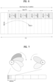
- FIG. 7 shows an example where analog beamforming is applied.
- the present invention describes an initial access procedure in the mmWave system, which is different from the conventional one due to the analog beamforming features.
- the present invention proposes not only how a UE and an eNB operate according to the changed initial access procedure but signaling information that should be exchanged between the UE and eNB and a method therefor.
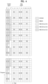
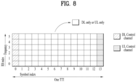
- FIG. 8 illustrates a self-contained subframe structure
- a self-contained subframe structure is considered in the new fifth-generation RAT.
- the hatched area represents the transmission region of a DL control channel (e.g., PDCCH) carrying the DCI
- the black area represents the transmission region of a UL control channel (e.g., PUCCH) carrying the UCI.
- the DCI is control information that the eNB transmits to the UE.
- the DCI may include information on cell configuration that the UE should know, DL specific information such as DL scheduling, and UL specific information such as UL grant.
- the UCI is control information that the UE transmits to the eNB.
- the UCI may include a HARQ ACK/NACK report on the DL data, a CSI report on the DL channel status, and a scheduling request (SR).
- SR scheduling request
- the region of symbols from symbol index 1 to symbol index 12 may be used for transmission of a physical channel (e.g., a PDSCH) carrying downlink data, or may be used for transmission of a physical channel (e.g., PUSCH) carrying uplink data.
- a physical channel e.g., a PDSCH
- a physical channel e.g., PUSCH
- DL transmission and UL transmission may be sequentially performed in one subframe, and thus transmission/reception of DL data and reception/transmission of UL ACK/NACK for the DL data may be performed in one subframe.
- the time taken to retransmit data when a data transmission error occurs may be reduced, thereby minimizing the latency of final data transmission.
- a time gap is needed for the process of switching from the transmission mode to the reception mode or from the reception mode to the transmission mode of the eNB and UE.
- some OFDM symbols at the time of switching from DL to UL in the self-contained subframe structure are set as a guard period (GP).
- a DL control channel can be Time Division Multiplexed (TDMed) with DL data or UL data and then transmitted.
- TDMed Time Division Multiplexed
- an eNB may transmit a DL control channel(s) over the entire band, but one UE may receive its DL control channel in specific partial band rather than the entire band.
- the DL control channel corresponding to information transmitted from the eNB to the UE may contain not only DL specific information such as DL scheduling but also information on a cell configuration and UL specific information such as UL grant.
- the new RAT system which is called the mmWave system or 5G system
- the minimum system bandwidth of 5 MHz, 10 MHz, 40 MHz, 80 MHz, etc. should be able to be supported.
- the minimum system band may vary according to the basic subcarrier spacing. For example, when the basic subcarrier spacing is respectively set to 15 kHz, 30 kHz, 120 kHz, and 240 kHz, the minimum system band may be 5 MHz, 10 MHz, 40 MHz, and 80 MHz, respectively.
- the new RAT system is designed such that it operates on not only 6 GHz or less but 6 GHz or more and a plurality of subcarriers are used in one system to support various scenarios and use cases.
- the length of a subcarrier When the length of a subcarrier is changed, the length of a subframe can increase/decrease according to the change in the subcarrier length.
- one subframe may be defined to have a short time period, for example, 0.5 ms, 0.25 ms, 0.125 ms, etc.
- the new RAT system will use high frequency band (e.g., 6GHz or higher) and support a subcarrier spacing greater than 15 kHz, i.e., the subcarrier spacing of the conventional LTE system.
- one resource unit RU can be defined as twelve subcarriers in the frequency domain and one subframe in the time domain.
- a UE To be associated with and served by a specific system, a UE should first perform the following operations. The UE should obtain the time and frequency synchronization of the corresponding system, receive basic System Information (SI), and adjust its uplink timing. In general, such a procedure is referred to as an initial access procedure, and the initial access procedure includes a synchronization procedure and an RACH procedure (i.e., random access procedure).
- SI basic System Information
- RACH procedure i.e., random access procedure
- a UE obtains OFDM symbol timing and subframe timing as well as a cell ID based on a PSS and an SSS, performs descrambling and decoding of a PBCH using the cell ID, and then obtains important information of the corresponding system.
- the basic synchronization procedure of the mmWave or new RAT system (hereinafter referred to as the mmWave/new RAT system) is similar to the above-described procedure, but the PSS/SSS transmission/reception method of the mmWave/new RAT system is significantly different from the conventional one.
- FIG. 9 illustrates examples of the time periods and resource regions of the new system where PSS/SSS/PBCH are transmitted. Specifically, FIG. 9(a) shows an example of the PSS/SSS/PBCH transmission period, and FIG. 9(b) shows an example of the PSS/SSS/ESS/PBCH transmission period.
- PSS/SSS/PBCH can be transmitted in different directions per OFDM symbol.
- the number of beam directions can be selected within the range of 1 to N.
- the number of beams (or beam directions) can be dynamically determined according to frequency or by considering cell interference.
- a UE can obtain symbol synchronization and a physical cell ID.
- the UE can obtain a cell ID by detecting a PSS and an SSS.
- PSS/SSS have been transmitted omni-directionally
- a method by which an eNB performs beamforming by rotating beam directions omni-directionally to transmit signals such as PSS/SSS/PBCH has been considered. That is, beam sweeping or beam scanning means transmitting and receiving signals by rotating beam directions as described above.
- the eNB can transmit signals such as PSS/SSS/PBCH in each of the N beam directions.
- the eNB transmits synchronization signals such as PSS/SSS/PBCH in each direction by sweeping the directions that the eNB can have or support.
- one beam group may be composed of several beams. PSS/SSS/PBCH can be transmitted in each beam group. In this case, one beam group includes one or more beams.
- a UE can acquire system timing as follows.
- a UE detects a PSS transmitted at a fixed location (for example, in 6 or x PRBs with respect to the center frequency) or a variable location. Similarly, the UE can obtain subframe timing and/or frame timing by detecting an SSS transmitted at a known location, that is, at a location relative to that of the PSS transmission resource. Then, by combining the PSS and the SSS, the UE can obtain a cell ID. To prevent signals transmitted through the SSS and relevant hypotheses from significantly increasing, the UE may obtain the subframe timing by detecting an additional synchronization signal (e.g., Extended Synchronization Signal (ESS)) transmitted from the eNB.
- ESS Extended Synchronization Signal
- a Beam Reference Signal can be transmitted for link quality measurement per beam direction.
- the BRS can be transmitted for the purpose of RSRP/RRM/RLM measurement, and it can be used for neighbor cell measurement.
- the BRS can be transmitted over the entire band to allow a UE to perform measurement over the entire band.
- the BRS may be an RS transmitted over the entire band per antenna port for an analog beam direction in which the PSS/SSS are transmitted.
- the UE should know information on the number of ports used for BRS transmission and the location of resources per port on which the BRS is transmitted in advance.
- the number of ports used for the BRS transmission that is, the number of BRS ports that the UE should measure at the corresponding time can be provided through the ESS.
- the eNB can inform the UE of ⁇ 1, 2, 4, 8 ⁇ , ⁇ 2, 4, 6, 8 ⁇ , or other combinations having different values through the ESS.
- informing the number of antenna ports through the ESS may mean that the UE should attempt to detect the number of antenna ports from the ESS based on multiple hypotheses for the number of antenna ports.
- the number of ports for a BRS that is transmitted in the same beam direction as a PBCH can be signaled on the PBCH.
- the UE should decode a PBCH of a neighbor cell and measure a BRS of the corresponding neighbor cell for neighbor cell measurement.
- an ESS can be transmitted on frequency resources different from those used for transmitting PSS/SSS within the same symbol.
- a UE may obtain subframe timing and frame timing from an ESS.
- the acquisition of subframe timing may mean obtaining the start location of a subframe, that is, information indicating how many symbols exist prior to the symbol detected by the UE in the corresponding subframe.
- frame timing may be related to the transmission periodicity of a synchronization signal. After detecting a synchronization signal, the UE may estimate the time required until the same synchronization signal arrives and be able to know how many subframes exist prior to a specific subframe in the corresponding time interval.
- the number of BRS ports can be indicated through the ESS.
- information on the number of DM-RS ports in a PBCH can be also indicated by the ESS.
- the number of PBCH DM-RS ports may be limited to 2.
- the number of PBCH DM-RS ports (for example, 1, 2, 4, or 8) may be indicated by the ESS.
- the ESS may carry information on the system bandwidth or BRS transmission bandwidth. In this case, for RSRP measurement, the UE may check resources used for BRS transmission without decoding the PBCH.
- an ESS sequence needs to be designed such that the UE can obtain information about how many symbols exist prior to the symbol where an ESS is present in a corresponding subframe.
- an ESS sequence should be a function of the cell ID and the index of the OFDM symbol in which a corresponding ESS is transmitted.
- FIG. 10 illustrates examples of a method for transmitting synchronization signals in the new system.
- the eNB may transmit the synchronization signals in a plurality of subframes.
- the synchronization signal means a signal transmitted from the eNB for synchronization such as PSS/SSS/SSS.
- SS Synchronization Signal
- the eNB can assume that B subframes are required to transmit all the SSs in respective directions of the B beams.
- FIG. 10 show a case in which B is 2. For example, it is assumed two subframes are required to transmit all SSs in each beam direction.
- SS1 and SS2 may represent part of a set of SSs with multiple beam directions or some SSs transmitted in different subframes.
- SSs may be divided into SS1 in a specific subframe and SS2 in another subframe for transmission thereof.
- SS1 and SS2 may be transmitted at a certain time interval as shown in FIG. 10(a) , or they may be transmitted in consecutive subframes as shown in FIG. 10(b) .
- the time required for the eNB to transmit next SS1 and SS2 after transmitting current SS1 and SS2 can be defined as the synchronization signal transmission periodicity.
- the time required for the eNB to transmit synchronization signals in all of its beam directions after transmitting synchronization signals in the same beam directions can be defined as the synchronization signal transmission periodicity.
- the synchronization signal transmission periodicity may be 2T subframes.
- an ESS sequence may contain information on how many subframes there are before the subframe in which the corresponding ESS sequence is transmitted.
- the ESS sequence may be generated as a function of the subframe index.
- a BRS sequence is generated as a function of the cell ID and symbol index and/or beam index.
- the BRS is generated as a function of the BRS antenna port number and BRS transmission subframe number.
- a PBCH DM-RS sequence is generated as a function of the cell ID, symbol index, PBCH transmission subframe number, and DM-RS port number.
- a PBCH may contain information such as basic system information, system frame number, the number of antenna ports, system bandwidth, etc. Additionally, the PBCH may contain information on PRACH configuration, time-frequency resources used for System Information Block (SIB) (i.e., SI) transmission (or the periodicity of SIB transmission), time-frequency resources used for paging transmission, etc.
- SIB System Information Block
- the PRACH configuration information may be included in the SIB (i.e., SI).
- the information on the time-frequency resources that can be used for the SIB and paging transmission may be independently signaled per beam direction (for example, per beam index).
- a UE Upon obtaining information on time-frequency resources that can be used for SIB and paging reception, a UE performs blind decoding for PDCCH detection in order to receive the corresponding information in the subframes designated for the SIB and paging reception.
- a UE-specific Search Space (USS) and a Common Search Space (CSS) are configured for a UE, the UE expects that a common channel is transmitted in subframes for the SIB/paging and then performs blind decoding of both the USS and CSS because the information on the SIB/paging transmission corresponds to system information.
- the UE does not perform blind decoding (BD) of the CSS on other subframes except the subframes for the SIB/paging.
- BD blind decoding
- the CSS may mean a search space for all UEs in a cell.
- it may mean a Group-specific Search Space (GSS) commonly allocated for a plurality of UEs rather than all UEs in a cell.
- GSS Group-specific Search Space
- a group RNTI or group ID that a UE should read may be determined as a function of the beam ID having the same symbol or beam direction as that of the PSS/SSS that the UE successfully receives and the cell ID. Even if the configuration of the group ID is not separately provided to the UE, the UE may determine the group ID after detecting the beam ID and cell ID.
- the UE may receive an RNTI value used for receiving group common data and control information (for example, the corresponding RNTI value is signaled to the UE).
- the UE may use the group ID for scrambling or as a DM-RS scrambling ID.
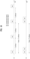
- FIG. 11 illustrate an example where system information is transmitted/received according to the present invention.
- SI system information
- a BCH with a periodicity of 40 ms
- SIB1 is transmitted on a DL-SCH with a periodicity of 80 ms
- other applicable SIBs are transmitted on a DL-SCH with time-frequency domain scheduling by an SI-RNTI on a PDCCH.
- Each of the applicable SIBs has a configurable periodicity and located within a time window.
- SI corresponding to carrier aggregation and/or Dual Connectivity is provided through dedicated signaling, which is a part of the Radio Resource Control (RRC) reconfiguration procedure for a (P)Scell for a configured UE.
- RRC Radio Resource Control
- Such an SI broadcasting approach is mainly suitable for macro cell deployment. However, this approach may not be optimal for other scenarios. That is, this broadcasting approach has a disadvantage in that resources are wasted, for example, when there are no or few UEs that camp on a cell, access to the system, and/or are interested in specific types of SIBs.
- Another disadvantage of the broadcasting approach is that when a UE obtains initial system information, latency occurs due to periodic broadcasting of the SI.
- the UE should wait for a period until a relevant SIB(s) is transmitted, and average delay corresponding to half of a configured period is typically required before the UE determines whether to access the features of the corresponding system.
- a further disadvantage is that as the system is developed and additional functions are added, the expandability of the broadcasting approach is impacted. As the amount of SI increases, the broadcasting approach requires more resources. Specifically, as new information messages are added, each of the messages may need to be broadcasted through a new time window. Since this means that the UE should wake up more frequently, it may affect the power consumption of the UE. In particular, when the broadcasting approach is applied to the new RAT system, there may be additional disadvantages.
- the new RAT may require multiple beams to provide proper coverage when it is deployed in high frequency bands (e.g., more than 6 GHz).
- high frequency bands e.g., more than 6 GHz.
- the broadcasting approach is used as in the conventional LTE/LTE-A system, that is, if SI is transmitted via each of the multiple beams, it may be inappropriate or inefficient.
- the new RAT deployment includes not only macro deployment but high-density cells with small coverage. In the case of cells with wide coverage, the broadcasting approach for all the applicable system information is appropriate to provide functions of system access, camping, mobility, etc.
- the new RAT system supports a short TTI, a UE can obtain system information more rapidly using a dedicated signal compared to waiting for system information broadcasting. This may be required to support URLLC services properly. Further, in a high-density deployment, the broadcasting approach may increase interference levels and affects the network power consumption.
- the present invention proposes on-demand SI to reduce the amount of broadcasted SI.
- the on-demand SI is provided when it is requested by a UE.
- some or all of the system information may be on-demand SI.
- all SI may be transmitted in an on-demand manner.
- some of the SI may be transmitted in an always-on manner, and the rest of the SI may be transmitted in an on-demand manner.
- the always-on SI may be common SI for all UEs transmitted in all beam directions of a corresponding cell.
- SI essential for initial access may be periodically broadcasted as the always-on SI, and except the broadcast minimum SI, the remaining SI may be the on-demand SI.
- the on-demand SI may be UE-group specific SI transmitted in a specific beam direction.
- An SI tag indicates whether there are changes in corresponding SI messages.
- an SI tag may be transmitted through a PBCH or an ESS.
- a UE requests SIB transmission through a RACH procedure (S1130).
- SIBs i.e., SI
- the UE may not read the SIBs in a predetermined cycle if the UE does not need the update.
- the UE requests the SItransmission through the RACH procedure, the UE should perform the RACH procedure based on out-of-date SI to obtain the updated SI because the UE does not have the updated SI.
- RACH resources available for the UE are determined in advance (S1110).
- the system may designate specific time/frequency or time/frequency/preambles for an SI request in advance.
- the UE receives first information regarding a random access -channel resource for a request of SI.
- the UE transmits a random access channel preamble on the random access channel resource based on the first information.
- RACH resources for an SI request may be shared by all UEs in a cell.
- RACH resources for an SI request may be designated per beam direction, that is, per SS block.
- RAR Random Access Response
- the network can transmit only updated SIBs instead of transmitting all SIBs.
- the eNB may broadcast SI in a corresponding cell (in a corresponding beam direction) or transmit corresponding system information through the RAR for a corresponding preamble index.
- scheduling information on a time/frequency region in which corresponding system information is transmitted in response to an SI request may be included in the RAR for the SI request and then transmitted.
- the UE receives the requested SI based on receiving the RAR.
- the UE may inform the eNB that the corresponding PRACH transmission is for requesting the SIBs through the message carried by the PRACH.
- the UE may explicitly inform, through the PRACH, that the purpose of the PRACH transmission is not to transmit specific data in UL but to receive specific data in DL, and more particularly, to request system information.
- the UE may set a field in the message carried by the PRACH to a specific value or transmit a specific sequence on the PRACH.
- separate PRACH resources or sequences for on-demand SIBs or PBCH transmission are reserved (by the eNB for a specific UE or a specific beam direction) (S1110).
- Such an indication may be transmitted in Msg1 or Msg3.
- a UE may attempt PRACH transmission and transmit an SI request in Msg3.
- FIG. 12 illustrates an example where an SS is transmitted per beam direction on a cell or carrier.
- FIG. 12 shows that SS blocks, and more particular, a plurality of SS blocks for multiple beams are consecutively transmitted, SS blocks for a set of beams may not be consecutively transmitted on a corresponding cell/carrier as shown in FIG. 10(a) .
- a UE may observe that the signal strength varies in each direction when detecting the PSS/SSS.
- the UE performs PSS/SSS detection with respect to PSS/SSS, which are transmitted per symbol in different directions, on a subframe in which the PSS/SSS are transmitted (hereinafter referred to as a PSS/SSS subframe).
- PSS/SSS subframe a subframe in which the PSS/SSS are transmitted.
- an ESS, a PBCH, and an RS for PBCH decoding hereinafter referred to as a PBCH DM-RS
- the UE can obtain the beam direction most suitable for the corresponding UE, that is, the beam direction where signals are received with the best channel quality. Then, by reporting the optimal beam direction or the resources where the PSS/SSS/PBCH with the best channel quality are present to the eNB, the UE can receive the PDCCH/PDSCH transmitted via the optimal beam. Similarly, for the PUSCH/PUCCH transmitted from the UE, the eNB may perform proper reception (RX) beamforming.
- RX proper reception
- an index or ID may be assigned to each beam (that is, each beam direction) or per beam group.
- a beam index may be tied with a symbol index where PSS/SSS/PBCH and BRS are transmitted so that the beam index may be implicitly promised/defined between the eNB and UE.
- a beam index may be tied with a symbol index where PSS/SSS/PBCH and BRS are transmitted and a BRS port number having the best reception quality in the corresponding symbol so that the beam index may be promised/defined between the eNB and UE.
- the signals transmitted in the same direction including PSS/SSS/PBCH can be defined as one SS block.
- the SS blocks may be separately indexed to distinguish therebetween.
- a specific SS block may indicate the transmission direction of a DL signal/channel such as PSS/SSS/PBCH.
- PSS/SSS/PBCH if PSS/SSS/PBCH are transmitted in 10 beam directions, the PSS/SSS/PBCH transmitted in the same direction may be configured as one SS block.
- the corresponding system could be interpreted to have 10 SS blocks. Since SS blocks are related to beam directions one-by-one, an SS block index could be interpreted to be a beam index.
- the index of a specific beam may be implicitly identified by the symbol index where the PSS/SSS corresponding to the cell ID are transmitted and the BRS port index with the best reception quality in the corresponding symbol.
- PSS/SSS transmission periodicity is P (e.g., P subframes) and an eNB needs B subframes to transmit all its beams, it is impossible to identify a beam index by simply using a cell ID and a symbol index.
- the eNB and UE can explicitly exchange a beam index with each other via an SSS, ESS, BRS (beam RS), or PBCH.
- BRS beam RS
- the BRS means an RS transmitted over the entire band to estimate a beam direction transmitted per symbol.
- a beam index may mean an index with an explicit number or order for beam directions.
- a beam index may mean a specific beam direction of a symbol where PSS/SSS are transmitted rather than an index with an explicit number or order for beam directions.
- a beam index may mean the direction of a beam transmitted via a BRS port with the best reception quality among the directions of specific beams transmitted from an eNB in a symbol where PSS/SSS are transmitted.
- a beam index may mean the index of a beam group including multiple beam directions and indicate a grouped beam direction having multiple beam directions.
- a beam index may mean an SS block index as described above.
- a UE may inform the eNB that which beam direction is most suitable for the corresponding UE without explicitly reporting the beam index as described above. That is, if a RACH resource is configured for and connected to each direction in which broadcast signals such as PSS/SSS/PBCH are transmitted, the UE can inform the best beam direction without signaling the beam index separately.
- the eNB may know that the beam direction optimized for the UE is the beam direction in which the PSS/SSS/PBCH connected to the specific RACH resource are transmitted.
- the eNB can estimate the beam index with the best reception quality from the perspective of the corresponding UE, that is, the SS block index from the RACH resource used by the UE to transmit the PRACH preamble.
- the UE may select a set of preferred beams using one or any combination of the following alternatives and list up a plurality of RACH resource candidates associated with the corresponding beams.
- the UE may also transmit the hypothesis/basis used for selecting the corresponding beam index or SS block index. For example, a UE may report the received signal quality together with the beam index or SS block.
- information on the received SINR of the PSS/SSS may be transmitted together with the corresponding beam index.
- information on the RSRP of the PBCH DM-RS may be transmitted together with the corresponding beam index.
- Alt3 or Alt4 if the beam or SS block is selected on the basis of a BRS, information on the RSRP of the BRS may be transmitted together with the corresponding beam index.
- the UE may report the quality of a DL signal received in the corresponding beam direction while performing UL transmission after RACH message 3 (Msg3).
- Msg3 RACH message 3
- the UE may select a plurality of optimal beam indices or SS block indices where the received signal quality is higher than a predetermined threshold and report to the network the selected DL beam directions and information on the DL received signal quality per beam direction. Specifically, the UE may report the information when transmitting RACH Msg3 or transmitting UL data thereafter.
- TRP Transmission and Reception Point
- PRACH preamble repetition or beam sweeping may be considered according to TX/RX reciprocal capability of a TRP (e.g., eNB) or UE.
- TX/RX reciprocal capability could be interpreted as TX/RX beam correspondence at the TRP and UE.
- the UE may be unable to transmit an uplink signal in the beam direction where the UE receives a downlink signal. This is because the UL optimal path may be different from the DL optimal path. If the TRP can determine a TRP RX beam for corresponding uplink reception based on UE's downlink measurements for one or more TX beams of the TRP and /or if the TRP can determine a TRP TX beam for corresponding downlink transmission based on TRP's uplink measurements for one or more RX beams of the TRP, the TX/RX beam correspondence at the TRP can be hold.
- the UE can determine a UE RX beam for corresponding uplink transmission based on UE's downlink measurements for one or more RX beams of the UE and/or if the UE can determine a UE TX beam for corresponding downlink reception based on an indication from the TRP, which is made based on uplink measurements for one or more TX beams of the UE, the TX/RX beam correspondence at the UE can be hold.
- RX beamforming should be applied to PRACH resources, which are used by a UE to attempt uplink random access, according to the direction in which an eNB transmits PSS/SSS for successful PRACH reception.
- the PRACH resources may be allocated per PSS/SSS direction, that is, per beam index (or SS block index).
- a RACH resource may be associated with each SS block index where PSS/SSS and PBCH are transmitted. Basically, a RACH resource may mean a time-frequency resource where an RACH preamble may be transmitted.
- PRACH resources means time-frequency resources used by a UE to transmit a PRACH, and information on PRACH sequences, root sequences, PRACH transmission power, maximum retransmission number, repetition number, etc. may be further included.
- the UE may inform the network of its preference for a specific SS block index using the time-frequency resources used by the UE for PRACH preamble transmission and a PRACH preamble index used by the UE.
- the PRACH time-frequency resources may include information on a subframe number that can be used to transmit a PRACH in the direction corresponding to a beam index (or value for indicating a corresponding subframe), symbol numbers in the corresponding subframe, the number of symbols in the corresponding subframe, a PRB index in the frequency domain (a value for indicating the location of a corresponding PRB in the frequency domain), and/or frequency-domain bandwidth, etc.
- PRACH resources for different beam indices or SS block indices may be TDMed. Assuming that an eNB performs RX beam scanning to receive an RACH for a single beam, a corresponding beam direction is reserved during a corresponding symbol or beam scanning duration regardless of whether there is RACH transmission.
- the UE can autonomously transmit an RACH preamble on RACH resources, it is assumed that the corresponding RACH resources are reserved at all times. To reduce this period, a number of UEs need to be multiplexed during a certain period by using the system bandwidth as much as possible. Thus, multiple PRACH resources can be configured in the frequency domain.
- UEs can be distinguished by using Code Division Multiplexing (CDM), by using Frequency Division Multiplexing (FDM) instead of the CDM or by using both of the CDM and FDM.
- CDM Code Division Multiplexing
- FDM Frequency Division Multiplexing
- information indicating that a UE prefers a specific SS block index or information indicating that the signal quality of the corresponding SS block index is good can be signaled if the UEs use different codes (e.g., preamble sequences).
- PRACH resources can be commonly configured for all beam indices. That is, time-frequency resources on which a UE can transmit a PRACH and an eNB can expect PRACH transmission from a UE may be commonly configured for all beam directions, or one time-frequency resource may be allocated per beam index group. When PRACH resources are commonly configured for multiple beams, latency can be reduced. When PRACH resources are commonly configured for multiple or all beams, PRACHs corresponding to a plurality of beam indices can be transmitted on one time-frequency resource. In other words, PRACH transmission time-frequency resources for UEs having different optimal beam directions may be shared between multiple UEs or between multiple beam indices. Alternatively, PRACH time-frequency resources may be configured in a cell-common manner.
- common PRACH resources it is assumed that a UE transmits a PRACH without using a specific beam, and the performance degradation caused when the eNB does not use RX beamforming may be overcome by PRACH repeated transmission and the like.
- whether common PRACH resources or PRACH resource where RX beams are assumed are selected can be determined by latency requirements, power constraint, RSRP, etc.
- how a UE transmits a PRACH may be slightly changed according to RACH resource selection. For example, in the case of transmission where no RX beam is assumed, the network may not know the beam optimized for the UE. In this case, there is a disadvantage in that a subsequent transmission channel such as an RAR may be transmitted without use of any TX beam.
- RACH resources may be fixedly reserved based on beam directions, and thus the disadvantage that the corresponding radio resources cannot be used by a UE with a different beam direction can be overcome.
- the network can dynamically adjust the amount of common RACH resources and the amount of RACH resources that depend on beam directions.
- the eNB may differently configure the power of the UE or dynamically inform the UE of the resource type (e.g., PUSCH resource) so that the UE can operate by changing the number of repetitions.
- the resource type e.g., PUSCH resource
- the eNB informs information on receiver gain semi-statically or dynamically so that the UE can determine its power and repetition.
- mutually promised RACH transmission resources may be distinguished from RACH transmission resources used by the eNB to receive a PRACH preamble by rotating the reception beam direction.
- the mutually promised RACH transmission resources may be distinguished from RACH transmission resources on which the eNB fixes the reception direction but the UE performs PRACH preamble transmission by rotating the transmission direction.
- the eNB may configure the beam direction where an RAR is transmitted together with RACH resources.
- the UE may not select the corresponding RACH resources. That is, although PRACH resources may be shared by all UEs, the PRACH resource may be sub-divided according to TX beam directions of the RAR transmission, and each UE may select its PRACH resources from among the sub-divided PRACH resources according to the RAR transmission beam directions. That is, the network instructs the eNB to use TX beams as described above but may also allow the eNB to perform the RACH reception without the RX beam scanning.
- RACH resources may be configured such that the eNB can perform reception beam scanning instead of being fixed in the reception beam direction.
- the above-described method by which RACH resources are shared by a plurality of SS block indices can be applied more effectively when the beam correspondence of an eNB or TRP is not matched.
- a UE may repeatedly transmit a PRACH preamble, and the TRP may perform the reception beam scanning operation to receive the PRACH preamble.
- the preamble indices used by the corresponding UE may be part of an index set associated with a specific SS block index.
- PRACH resource configuration information includes a time-frequency resource region that can be used by a UE for PRACH transmission, a PRACH transmission preamble index, preamble transmission power, RA-RNTI information used for PRACH transmission.
- the PRACH resources may be separately configured per beam index or SS block index, and the information included in the PRACH configuration may be independently configured per beam index or SS block.
- the preamble index, preamble transmission power, and RA-RNIT may vary per beam index or SS block index.
- All or some of the information included in the PRACH configuration may be beam-index-specific.
- the time-frequency resources available for PRACH transmission may be shared by a plurality of beam indices or all beam indices, and in this case, the PRACH time-frequency resources in the PRACH configuration may be common for beam indices included in a specific beam index group or all beam indices. However, each piece of information should be transmitted per beam index.
- an RAR window size and time-frequency resource for RAR transmission may be configured/signaled per beam index (e.g., SS block index).
- the RAR window and/or time-frequency resources for the RAR transmission may be common for multiple beam indices.
- RACH configuration information may include configuration information on the RAR, and it can be provided to a UE(s).
- the RAR configuration information representatively contains information on a time-frequency region where the RAR is transmitted. Details will be described later.
- Information on the PRACH resource configuration corresponding to a beam index can be transmitted on a channel different from that transmitted in a symbol where the PSS/SSS with the same beam index as that of the corresponding PRACH resources are present. The following options can be applied to channels capable of carrying the PRACH configuration.
- a UE may select a plurality of beam indices/directions for the beam direction that is preferred by the UE or has the best reception quality and obtain PRACH configuration information per beam index or beam direction. That is, an eNB may transmit the PRACH configuration information per beam index.
- a plurality of SS blocks may be defined. Each of the plurality of SS blocks may be transmitted in its unique DL transmission beam direction.
- RACH resources may be configured per SS direction.
- the UE may receive signals/channels in SS blocks and select an SS block index with the best reception quality.
- the UE may transmit a PRACH preamble by selecting the RACH resources associated with the corresponding SS block index. In this case, the UE may select one or more SS block indices and attempt the PRACH preamble transmission on RACH resources associated with each of the SS blocks.
- a random access channel resource is associated with a synchronization signal block among a plurality of synchronization signal blocks.
- load information can be signaled as RACH configuration information per SS block.
- This load information may be used to restrict RACH transmission for a specific SS block index, and more specifically, restrict to make a random access attempt using a specific RACH resource.
- a transmission power offset may be signaled as RACH configuration information per SS block index.
- the UE may calculate an actual received signal level by adding or subtracting the signaled power offset.
- the power offset may enforce a UE to select a specific SS block index and attempt a RACH procedure by using an RACH resource associated with the selected SS block or prohibit the UE from selecting the specific SS block index.
- an RAR message includes an RACH preamble sequence index detected by an eNB, a Timing Advance (TA) command for adjusting UE's uplink transmission timing, uplink transmission power information, power ramping information, UL grant for Msg3 transmission, a temporary ID, etc.
- TA Timing Advance
- RAR transmission generally indicates that UE's RACH transmission is successful.
- a UE upon receiving an RAR for a RACH preamble which has been transmitted on a specific cell/carrier, a UE performs uplink transmission based on the corresponding RAR unless a radio link on the corresponding cell/carrier is disconnected or a RACH procedure is retriggered by a PDCCH order and the like, instead of retransmitting the RACH preamble.
- an RAR may include network load information in a specific beam direction. That is, by signaling whether there are large or small loads, an eNB may allow a UE who transmits a corresponding preamble to make RACH attempt to another beam. If receiving an RAR indicating that there are large loads in the direction where the PRACH is transmitted, the UE performs a RACH procedure for another beam direction on the corresponding cell/carrier even though the UE receives the RAR for the PRACH transmission corresponding to the corresponding beam direction.
- the load information in an RAR may be used as a beam switching command.
- the network may designate a separate preamble for beam switching in an RAR message.
- the eNB may inform preamble transmission power for another beam direction. If the RAR containing the beam switching instruction has no signaling related to transmission power, the UE may consider the PRACH transmission for another beam direction as PRACH retransmission and then perform the retransmission by ramping up the power. In this case, the UE may select a beam direction with the best quality among beam directions except the beam direction in which the load information is signaled and then transmit a PRACH preamble for the selected beam direction.
- the RAR configuration for each PRACH configuration may be established independently or commonly.
- a UE may expect that an RAR will be transmitted within a specific window after k subframes or a specific time from the PRACH transmission time.
- the UE may expect that the RAR for a PRACH will be transmitted within a predetermined time period (i.e., time window) from the k-th subframe (or specific time) after the UE transmits the PRACH.
- the UE may expect that an RAR for the PRACH will be received within a specific time period (i.e., RAR arrival window) from subframe k.
- RAR arrival window may be signaled/defined per PRACH configuration. In other words, these two values may be signaled/defined per beam index.
- the value of k and the RAR arrival window may be signaled or defined commonly for all PRACH configurations.
- each beam direction has a different PRACH resource, multiple RACHs belonging to the same beam-group may share the same RAR window.
- the UE may expect that an RAR(s) for the PRACH preambles will be received on the same time resource.
- FIG. 13 illustrates Random Access Response (RAR) message formats according to the present invention.
- a UE transmits preamble 1 on an RACH resource for beam index A and (the same/a different) UE transmits preamble 2 on an RACH resource for beam index B.
- an RAR for preamble 1 and an RAR for preamble 2 can be transmitted in the same window.
- responses for multiple PRACHs may be transmitted as a single RAR message.
- responses for PRACH transmission for various beam indices or SS blocks may be included in one RAR message.
- which PRACH response in an RAR message corresponds to which beam index may also be signaled.
- responses for RACH preamble transmissions associated with the plurality of beam indices may be transmitted in one RAR message.
- beam indices for individual PRACH responses are signaled in one RAR message.
- an RAR may be transmitted per beam index.
- each RAR message carries a corresponding beam index.
- PRACH responses for a corresponding beam index may be transmitted in an RAR message.
- RAR 1 and RAR 2 for preamble 1 and preamble 2, which are transmitted for beam direction A are transmitted together with beam index A in one RAR message
- RAR 1 and RAR 2 for preamble 1 and preamble 2, which are transmitted for beam direction B are transmitted together with beam index B in another RAR message.
- M RAR message reception time units corresponding to N PRACH signals may be deployed consecutively or uniformly.
- M may be equal to or less than N
- N may be equal to or less than K.
- a UE may perform RAR detection/reception operation as follows. The UE first performs PRACH signal transmission through a PRACH time unit corresponding to its preferred beam index and sequentially checks beam indices included in a received RAR, for example, starting at the first RAR time unit in the RAR window.
- the UE may perform subsequent operation (e.g., Msg3 transmission) according to the corresponding RAR and stop the RAR detection/reception operation in the corresponding RAR window.
- subsequent operation e.g., Msg3 transmission
- the UE may consider that the RAR reception fails and then perform subsequent operation (e.g., PRACH signal retransmission, PRACH power ramping, and/or PRACH transmission count increment).
- subsequent operation e.g., PRACH signal retransmission, PRACH power ramping, and/or PRACH transmission count increment.
- the eNB can efficiently use resources by configuring/transmitting only the RAR for the actually received PRACH in the RAR window. For example, the eNB may transmit RARs in first some symbols/periods within the RAR window and transmit DL/UL data/control channels in the remaining symbols.
- the random access procedure of the 3GPP LTE system can be summarized as follows.
- the L1 random access procedure encompasses the transmission of random access preamble and random access response.
- the remaining messages are scheduled for transmission by the higher layer on the shared data channel and are not considered part of the L1 random access procedure.
- a random access channel occupies 6 resource blocks in a subframe or set of consecutive subframes reserved for random access preamble transmissions.
- the eNB is not prohibited from scheduling data in the resource blocks reserved for random access channel preamble transmission. The following steps are required for the L1 random access procedure.
- the random access procedure at the medium access control (MAC) layer can be performed as follows.
- information on UL transmission power for PRACH preamble transmission is included in an RACH configuration and transmitted to a UE.
- UE-common random access parameters such as preamblelnitialReceivedTargetPower, powerRampingStep, preambleTransMax, etc. are transmitted to the UE through an RRC signal (see PRACH-Config of TS 36.331).
- PREAMBLE_TRANSMISSION_COUNTER starts from 1 and increases by 1 whenever preamble transmission is attempted. The maximum number of times that preamble transmission can be performed is defined as preambleTransMax, and the preamble transmission can be repeatedly performed no more than preambleTransMax.
- DELTA_PREAMBLE has the following predefined values (see Table 7.6-1 of 3GPP TS 36.321). Table 2 Preamble Format DELTA PREAMBLE value 0 0 dB 1 0 dB 2 -3 dB 3 -3 dB 4 8 dB
- the PRACH preamble transmission power is determined according to equation (1) below.
- P PRACH min ⁇ P CMAX(i), PREAMBLE_RECEIVED_TARGET_POWER+PL c ⁇ _[dBm].
- a plurality of SS blocks can be defined. Specifically, a plurality of SS blocks are defined, and each of the SS blocks can be transmitted in its unique DL transmission beam direction.
- a RACH resource may be configured per SS block.
- a UE may receive signals/channels in the SS blocks and select an SS block index with the best reception quality.
- the UE may select an RACH resource associated with the corresponding SS block index and transmit a PRACH preamble on the selected resource. In this case, the UE may select one or more SS block indices and attempt PRACH transmission on the RACH resource associated with each SS block.
- the UE attempts the PRACH transmission again and repeat the above-described processes. It is called PRACH retransmission. Whenever performing the PRACH retransmission, the UE ramps up the PRACH transmission power by a certain degree. That is, the UE performs the retransmission according to the number of allowed PRACH retransmission rounds. Whenever performing the retransmission, the UE ramps up the power, but the ramped-up power cannot exceed the maximum transmission power.
- PREAMBLE_TRANSMISSION_COUNTER the number of times that PRACH retransmission can be performed.
- the PRACH preamble transmission power of the LTE system is determined according to Equation (1) above and Equation (2) below.
- PREAMBLE_RECEIVED_TARGET_POWER preambleInitialReceivedTargetPower + DELTA_PREAMBLE + (PREAMBLE_TRANSMISSION_COUNTER-1) * powerRampingStep.
- PRACH preamble repetition or beam sweeping may be considered according to TX/RX reciprocal capability of a TRP or UE.
- the TX/RX reciprocal capability could be referred to as TX/RX beam correspondence at the TRP and a UE. If the TRP and UE cannot maintain the TX/RX reciprocal capability in the multi-beam environment, the UE may be unable to transmit an uplink signal in the beam direction where the UE receives a downlink signal. This is because the UL optimal path may be different from the DL optimal path.
- the TRP can determine a TRP RX beam for corresponding uplink reception based on UE's downlink measurements for one or more TX beams of the TRP and /or if the TRP can determine a TRP TX beam for corresponding downlink transmission based on TRP's uplink measurements for one or more RX beams of the TRP, the TX/RX beam correspondence at the TRP can be hold.
- the UE can determine a UE RX beam for corresponding uplink transmission based on UE's downlink measurements for one or more RX beams of the UE and/or if the UE can determine a UE TX beam for corresponding downlink reception based on an indication from the TRP, which is made based on uplink measurements for one or more TX beams of the UE, the TX/RX beam correspondence at the UE can be hold.
- FIG. 14 illustrates PRACH transmission according to the present invention.
- FIG. 14 shows that PRACH resources for a set of beam directions applied to a cell/carrier are consecutive in the time domain, the PRACH resources can be arranged nonconsecutively.
- FIG. 14 shows the PRACH resources for the set of beam directions available on the cell/carrier are the same in the frequency domain, different frequency resources may be configured.
- An RACH resource can be defined per beam direction in which an SS is transmitted, or per SS block. At this time, the corresponding RACH resource may be sub-divided into RACH basic units.
- the RACH basic unit can be defined as a time-frequency resource used for transmitting one PRACH preamble.
- one PRACH resource configured for one beam direction or SS block can be segmented into two RACH basic units.
- FIG. 14 shows that one PRACH resource is segmented into two RACH basic units, the PRACH resource may be segmented into three or more RACH basic units.
- One-time PRACH attempt may mean that a PRACH preamble is transmitted on a RACH resource defined per SS block.
- preamble repetition or beam sweeping is performed on the corresponding RACH resource, it may be considered as one-time PRACH attempt.
- a UE transmits RACH preambles on the same RACH resource by changing a beam direction according to RACH basic units it may be considered as one-time PRACH attempt.
- a plurality of PRACH preambles are transmitted using different RACH basic units on the same RACH resource, it is not considered as retransmission. For example, referring to FIG.
- a UE transmits RACH preambles on RACH basic units of a PRACH preamble resource for SS block 1 (in different directions), this may be considered as one-time RACH transmission attempt.
- transmission power may not increase per preamble transmission.
- an RACH preamble is transmitted on a next RACH resource (that is, when a UE stands by during an RAR window for RAR reception and then transmits an RACH preamble on an RACH resource after the RAR window) or if a PRACH preamble is transmitted on a PRACH resource associated with another beam/SS block, it is considered as retransmission.
- a next RACH resource that is, when a UE stands by during an RAR window for RAR reception and then transmits an RACH preamble on an RACH resource after the RAR window
- a PRACH preamble is transmitted on a PRACH resource associated with another beam/SS block
- a UE may transmit a RACH preamble on a next PRACH preamble resource for SS block 1 or a PRACH preamble resource associated with another SS block.
- the RACH preamble transmission is considered different from the previous RACH preamble transmission.
- PREAMBLE_TRANSMISSION_COUNTER of Equation (2), which indicates how many times PRACH preamble retransmission is performed, increases.
- the amount of ramped-up power may vary per beam index.
- the amount of power ramped up by a UE may be configured/signaled independently between beam indices, and the power increase for retransmission may be computed per beam index.
- the calculation of PREAMBLE_TRANSMISSION_COUNTER is performed by collecting all RACH resources even if different beam directions, i.e., different RACH resources are used.
- PRACH transmission power is obtained by calculating how many times each UE performs PRACH preamble transmission instead of calculating how many times the PRACH preamble transmission is performed per RACH resource.
- RACH transmission fails even though power is ramped up by attempting the RACH transmission for beams with good quality, the delay of the RACH transmission increases if the power is set to the default value on the next RACH resource.
- path loss values may vary.
- the UE compensates for the path loss of the PRACH preamble transmission power in each RACH resource used for the PRACH preamble transmission. For example, assuming that RACH resource j is associated with beam direction or SS block index j, PRACH transmission power P PRACH,j on RACH resource j can be defined by Equations (3) and (4).
- P PRACHj min ⁇ P CMAX,c(i), PREAMBLE_RECEIVED_TARGET_POWER+PL c,beam(j) ⁇ _[dBm].
- P CMAX,c (i) is the configured UE transmit power for subframe i of serving cell c
- PL c,beam(j) is the downlink path loss estimate calculated in the UE for beam direction j (or SS block index j) of serving cell c.
- PREAMBLE_RECEIVED_TARGET_POWER preambleInitialReceivedTargetPower + DELTA_PREAMBLE + (PREAMBLE_TRANSMISSION_COUNTER-1) * powerRampingStep(j). where, if powerRampingStep is configured RACH resource common, powerRampingStep(j) is powerRampingStep.
- preambleInitialReceivedTargetPower and preamble formats are configured per RACH resource (i.e., per beam direction or SS block index)
- preamblelnitialReceivedTargetPower and DELTA_PREAMBLE can be respectively changed to preambleInitialReceivedTargetPower (j) and DELTA_PREAMBLE(j) in Equation 4.
- the network can configure and signal the number of RACH resources that can be used by the UE.
- the network may configure offsets for received signal levels of the best and second best beams and then transmit the offsets by including them in a RACH configuration.
- offsets for received signal levels of the best, second best, third best beams are signaled. This may mean that the UE can attempt the PRACH preamble transmission with respect to beams only within the corresponding offsets as wells as the best beam.
- a plurality of RACH resources can be allocated for a UE.
- a method by which the UE selects a RACH resource for a random access procedure among the plurality of RACH resources will be described.
- the method for selecting a RACH resource for a random access procedure, i.e., RACH procedure will be described relating to a PRACH retransmission method.
- a UE when a UE performs PRACH transmission, if a plurality of SS blocks are received above a certain level, in other words, if the UE has multiple preferred beam indices, the UE first transmits a PRACH for an SS block with the highest received signal strength (i.e., the best beam index). If the UE does not receive an RAR for the corresponding PRACH within a given RAR window, the UE retransmits the PRACH for the corresponding beam index.
- the UE preferentially transmits a PRACH preamble on a RACH resource associated with the SS block index with the highest received signal strength, and when the retransmission is required, the UE preferentially attempts to transmit a PRACH preamble for the SS block index with the highest received signal strength.
- a UE prefers three beam indices: beam indices a, b and c.
- beam index a is the best beam
- beam index c is the beam with the lowest quality.
- the numbers of retransmission rounds for beam indices a, b and c are denoted by Ra, Rb and Rc, respectively.
- the UE may attempt retransmission for the beam index with the second best quality Rb times (where Rb ⁇ 1). If the UE still does not receive any RAR in spite of attempting the PRACH retransmission Rb times, the UE may attempt retransmission for the beam index with the third best quality Rc times (where Rc ⁇ 1).
- the number of PRACH preamble retransmission rounds for each SS block may be independently defined or configured. The UE preferentially attempts to transmit a PRACH preamble for the SS block index with the highest received signal strength.
- the UE attempts retransmission for the SS block index with the highest received signal strength as many times as possible within the maximum number of retransmission rounds. If the UE still does not receive any RAR from the network despite the retransmission attempts or if the UE does not completes the RACH procedure due to contention resolution failure even though the UE receive a RAR, the UE may attempt the PRACH transmission for the SS block with the second best received quality.
- the UE Whenever the UE performs PRACH retransmission, the UE ramps up power by a value (delta) signaled to the UE. That is, whenever a PRACH for beam index a is transmitted, power is ramped up. The PRACH for beam index a is retransmitted Ra times, and the power is ramped up every retransmission until the maximum power is reached. When the maximum power is reached, the retransmission for beam index a is performed with the maximum power. If the UE does not receive an RAR even though the UE retransmits the PRACH for beam index a Ra times, the UE transmits a PRACH for beam index b on a PRACH resource associated with beam index b.
- a value (delta) signaled to the UE That is, whenever a PRACH for beam index a is transmitted, power is ramped up. The PRACH for beam index a is retransmitted Ra times, and the power is ramped up every retransmission until the maximum power is
- the UE When the UE transmits the PRACH for the beam index b, the UE should reset or initialize the transmission power. That is, the maximum power used for the PRACH transmission for beam index a is not used. As if the PRACH was transmitted at the first time, the PRACH for beam index b is transmitted at the power used for the initial transmission. Thereafter, if the UE does not receive an RAR, the power is ramped up. Similarly, if the UE does not receive an RAR in spite of retransmitting the PRACH for beam index b Rb times, the UE transmits a PRACH for beam index c, which has the next best quality.
- the UE may calculate the initial transmission power with respect to the received signal strength (e.g., RSRP) of the SS block associated with the corresponding RACH resource similar to the power control method described in Method 1. That is, when the UE performs the PRACH preamble retransmission, the PRACH preamble transmission power may compensate for the path loss in each RACH resource or SS block index used for the PRACH preamble transmission.
- the received signal strength e.g., RSRP
- the UE may report this fact to higher layers and then perform cell reselection operation. For example, unlike the power control method described in Method 1, in the case of RACH retransmission for different beam indices, the UE may attempt power ramping per beam index using a separate power ramping counter per beam index. That is, when the UE performs RACH preamble retransmission for a different beam index (i.e., SS block index), retransmission rounds are not counted unlike Method 1 where retransmission rounds are counted regardless of beam indices (i.e., SS block indices).
- a UE when a UE performs PRACH transmission, if a plurality of SS blocks are received above a certain signal strength level, in other words, if the UE has multiple preferred beam indices, the UE first transmits a PRACH for an SS block with the highest received signal strength (i.e., the best beam index). For example, when the UE has multiple preferred beam indices, the UE first transmits a PRACH for the best beam index. Thereafter, if the UE does not receive an RAR for the corresponding PRACH within a given RAR window, the UE transmits a PRACH for the beam index with the second best reception quality.
- the UE If the UE does not receive an RAR for the corresponding PRACH in the RAR window, the UE transmits a PRACH for the beam index with the third best reception quality.
- the UE may perform PRACH preamble retransmission by sequentially selecting RACH preamble transmission for the plurality of SS block indices according to the SS block reception quality.
- a UE performs PRACH preamble transmission with respect to a number of RACH resources, it may degrade the system performance due to the ping-pong effect.
- restrictions may be imposed on the number of PRACH resources where a UE can attempt the PRACH preamble transmission and the reception quality range of associated SS blocks.
- a network may signal the maximum number of SS blocks where a UE makes RACH attempts or the number of RACH resources, an offset value from the received signal strength of the best SS block, etc. via a PRACH configuration.
- the offset may be used to allow the RACH preamble transmission only for SS block indices within a certain range from the received signal strength of the best SS block.
- the UE may transmit a PRACH based on the second best quality. In this case, the UE may consider it as PRACH retransmission and then ramp up the power. However, since although it is considered as the PRACH retransmission from the perspective of the UE, the corresponding transmission is PRACH transmission for another beam index, it is preferred not to ramp up the power. Thus, when the UE transmits individual PRACHs for a set of the preferred beam indices, if the UE transmits the PRACH for the specific beam index for the first time, the UE does not ramp up the power.
- the UE transmits the PRACH for the best beam index again by ramping up the power.
- the UE may attempt the power ramping-up per beam index by separately using a power ramping counter per SS block index (or beam index) as mentioned in Alt a.
- path loss values may vary.
- the UE may compensate for the path loss in each RACH resource or SS block index used for the corresponding PRACH preamble transmission using the corresponding PRACH preamble transmission power.
- a UE prefers three beam indices: beam indices a, b and c.
- beam index a is the best beam
- beam index c is the beam with the lowest quality.
- the numbers of retransmission rounds for beam indices a, b and c are denoted by Ra, Rb and Rc, respectively. If the UE does not receive an RAR after transmitting a PRACH for beam index a, the UE transmits a PRACH for beam index b. If the UE receive no RAR for the PRACH for beam index b, the UE transmits a PRACH for beam index c.
- the UE transmits the PRACH for beam index a again by ramping up the power. If the UE still does not receive an RAR for the PRACH for beam index a, the UE transmits the PRACH for beam index b, which is the next beam index, with the ramped up power, that is the power that is previously used for transmitting the PRACH for beam index a. Similarly, if the UE does not receive an RAR for the PRACH for the beam index b, the UE transmits the PRACH for beam index c with the same power. That is, the UE can perform the PRACH retransmission for each beam index by ramping up the power as described above.
- the UE may ramp up the power.
- the UE may use the previous power as it is without resetting or initializing the PRACH transmission power. That is, when the UE performs the retransmission on the same RACH resource, the UE may ramp up the power.
- the UE may maintain the previous PRACH preamble transmission power.
- a UE receives a plurality of SS blocks above a certain signal strength level, in other words, if the UE has multiple preferred beam indices, the UE can transmit PRACH preambles for the plurality of SS blocks. That is, if the UE does not receive an RAR for any one of the beam indices after transmitting respective PRACHs for the plurality of beam indices, the UE may attempt the PRACH transmission again. For example, after respectively transmitting PRACHs for beam indices a, b and c, the UE may wait for RARs for the transmitted PRACHs in the same window or overlapping windows.
- the UE may transmit a PRACH for another beam index.
- the UE may retransmits the PRACHs for beam indices a, b and c. In this case, the UE ramps up and transmits the PRACH for each of the beam indices.
- the UE may transmit a plurality of PRACHs without waiting for RAR reception. However, if PRACHs are for the same beam index, the UE cannot perform the PRACH transmission until receiving an RAR, that is, before reaching a new RAR transmission window. In other words, only when PRACHs are for different beam indices, the UE can perform the PRACH transmission without waiting for the RAR reception.
- the UE may determine the PRACH transmission order and the number of PRACH transmission rounds when performing the round robin rotation for the beam indices. Preferably, the best beam index starts first. When a specific beam index has channel quality above a certain threshold, if the reception quality of the specific beam index is significantly different from that of another beam index, the UE may attempt PRACH transmission for the beam index with the better quality more frequently.
- the UE may attempt RACH transmission in the form of [a, b, a, b, c, a, b, a, b, c,..] rather than [a, b, c, a, b, c,..].
- the power ramping principle can be established such that in the case of retransmission for the same beam index, power is ramped up, and for different beam indices, power is ramped up by the number of retransmission rounds for a corresponding beam index.
- the first available PRACH resource is the first available resource among available RACH resources or the resource capable of reducing the total delay maximally.
- the RACH resource corresponding to the beam with a largest amount of resources may be selected as the first available PRACH resource, or an RACH resource may be selected as the first available PRACH resource by considering loads and the like as described above.
- the maximum number of times that a UE can perform PRACH (re)transmission should be defined.
- the maximum retransmission number can be mainly defined according to the following two method.
- Rmax the maximum PRACH transmission number per UE, Rmax may be signaled.
- Configuring PRACH resources per beam may cause resource waste.
- the UE may require beamforming.
- it is desirable to configure PRACH resources per beam index but in the case of UEs located at the cell center, the eNB does not need to perform RX beamforming.
- PRACH resources can be differently configured.
- a UE may transmit a PRACH on common PRACH resources, and the eNB may be configured not to perform the RX beamforming on the corresponding resources. Since the corresponding resource region is not limited to a specific beam direction, it is possible to avoid resource waste. If UEs are located at the cell center, the UEs may have almost no propagation loss or blockage.
- Such UEs i.e., UEs with excellent channel states may be configured to perform PRACH transmission on resources where omni-direction reception is possible.
- common PRACH resources can be separately allocated.
- the UEs may repeatedly transmit PRACHs on the common PRACH resources regardless of beam indices.
- the UE may transmit a PRACH per beam index using beam-index-specific PRACH resources according to the aforementioned methods.
- a UE transmits a PRACH for the best beam index. And, if no RAR is transmitted within a given window, the UE attempts the PRACH transmission for the corresponding beam index again. The UE may attempt the retransmission x times (where x ⁇ 1). If the UE fails to receive an RAR after performing the retransmission x times, the UE transmits a PRACH for the beam index with the second best quality and then waits to receive an RAR within the given window. Similarly, if the UE receives no RAR for the corresponding PRACH, the UE may perform PRACH retransmission for the corresponding beam index y times (where y ⁇ 1).
- the UE may attempt PRACH transmission for the beam index with the third best quality.
- the number of times that the UE attempts the PRACH transmission may be different per beam index, and in this case, if a specific beam index has better reception quality, the number of PRACH attempts for the specific beam index may increase.
- a UE After transmitting a PRACH for a specific beam index, a UE may receive an RAR for the corresponding PRACH. In this case, the UE may transmit its C-RNTI and a set of preferred beam indices (e.g., SS block indices) if possible. After receiving the report about the beam indices, an eNB may select a specific beam index from the corresponding beam index set and transmit the selected beam index when scheduling the corresponding UE.
- a set of preferred beam indices e.g., SS block indices
- PRACH Message 3 may contain the index of one preferred beam, which is obtained by a UE through downlink beam RS measurement or N beam indices (where N is a random integer greater than 1) and the received signal strength for the corresponding beam indices (e.g., RSRSP).
- N is a random integer greater than 1
- RSRSP received signal strength for the corresponding beam indices
- an eNB Upon receiving RACH Message 3 from a UE, an eNB transmits RACH Message 4 to the corresponding UE.
- RACH Message 4 is transmitted for contention resolution.
- an eNB based on best N beam indices (beam information) reported by a UE, an eNB signals a beam index to be used for data transmission to the corresponding UE in RACH Message 4.
- the eNB can signal one or more beam indices.
- the UE expect that its PDCCH/PDSCH will be transmitted in the direction corresponding to the signaled beam index and may perform RX beamforming in the corresponding direction.
- the UE transmits a PUSCH the UE may perform uplink transmission such as PUSCH/PUCCH in the direction corresponding to the signaled beam index.
- a UE may report its preferred beam indices as follows. The following methods can also be used when UE's preferred beam directions are changed/added.
- FIG. 11 is a block diagram illustrating elements of a transmitting device 10 and a receiving device 20 for implementing the present invention.
- the transmitting device 10 and the receiving device 20 respectively include Radio Frequency (RF) units 13 and 23 capable of transmitting and receiving radio signals carrying information, data, signals, and/or messages, memories 12 and 22 for storing information related to communication in a wireless communication system, and processors 11 and 21 operationally connected to elements such as the RF units 13 and 23 and the memories 12 and 22 to control the elements and configured to control the memories 12 and 22 and/or the RF units 13 and 23 so that a corresponding device may perform at least one of the above-described examples of the present invention.
- RF Radio Frequency
- the memories 12 and 22 may store programs for processing and controlling the processors 11 and 21 and may temporarily store input/output information.
- the memories 12 and 22 may be used as buffers.
- the processors 11 and 21 generally control the overall operation of various modules in the transmitting device and the receiving device. Especially, the processors 11 and 21 may perform various control functions to implement the present invention.
- the processors 11 and 21 may be referred to as controllers, microcontrollers, microprocessors, or microcomputers.
- the processors 11 and 21 may be implemented by hardware, firmware, software, or a combination thereof. In a hardware configuration, application specific integrated circuits (ASICs), digital signal processors (DSPs), digital signal processing devices (DSPDs), programmable logic devices (PLDs), or field programmable gate arrays (FPGAs) may be included in the processors 11 and 21.
- ASICs application specific integrated circuits
- DSPs digital signal processors
- DSPDs digital signal processing devices
- PLDs programmable logic devices
- FPGAs field programmable gate arrays
- firmware or software may be configured to include modules, procedures, functions, etc. performing the functions or operations of the present invention.
- Firmware or software configured to perform the present invention may be included in the processors 11 and 21 or stored in the memories 12 and 22 so as to be driven by the processors 11 and 21.
- the processor 11 of the transmitting device 10 performs predetermined coding and modulation for a signal and/or data scheduled to be transmitted to the outside by the processor 11 or a scheduler connected with the processor 11, and then transfers the coded and modulated data to the RF unit 13.
- the processor 11 converts a data stream to be transmitted into K layers through demultiplexing, channel coding, scrambling, and modulation.
- the coded data stream is also referred to as a codeword and is equivalent to a transport block which is a data block provided by a MAC layer.
- One transport block (TB) is coded into one codeword and each codeword is transmitted to the receiving device in the form of one or more layers.
- the RF unit 13 may include an oscillator.
- the RF unit 13 may include N t (where N t is a positive integer) transmit antennas.
- a signal processing process of the receiving device 20 is the reverse of the signal processing process of the transmitting device 10.
- the RF unit 23 of the receiving device 20 receives radio signals transmitted by the transmitting device 10.
- the RF unit 23 may include N r (where N r is a positive integer) receive antennas and frequency down-converts each signal received through receive antennas into a baseband signal.
- the processor 21 decodes and demodulates the radio signals received through the receive antennas and restores data that the transmitting device 10 intended to transmit.
- the RF units 13 and 23 include one or more antennas.
- An antenna performs a function for transmitting signals processed by the RF units 13 and 23 to the exterior or receiving radio signals from the exterior to transfer the radio signals to the RF units 13 and 23.
- the antenna may also be called an antenna port.
- Each antenna may correspond to one physical antenna or may be configured by a combination of more than one physical antenna element.
- the signal transmitted from each antenna cannot be further deconstructed by the receiving device 20.
- An RS transmitted through a corresponding antenna defines an antenna from the view point of the receiving device 20 and enables the receiving device 20 to derive channel estimation for the antenna, irrespective of whether the channel represents a single radio channel from one physical antenna or a composite channel from a plurality of physical antenna elements including the antenna.
- an antenna is defined such that a channel carrying a symbol of the antenna can be obtained from a channel carrying another symbol of the same antenna.
- An RF unit supporting a MIMO function of transmitting and receiving data using a plurality of antennas may be connected to two or more antennas.
- a UE operates as the transmitting device 10 in UL and as the receiving device 20 in DL.
- an eNB operates as the receiving device 20 in UL and as the transmitting device 10 in DL.
- a processor, an RF unit, and a memory included in the UE will be referred to as a UE processor, a UE RF unit, and a UE memory, respectively, and a processor, an RF unit, and a memory included in the eNB will be referred to as an eNB processor, an eNB RF unit, and an eNB memory, respectively.
- the eNB processor may control the eNB RF unit to transmit a synchronization signal, a broadcast signal, and system information in accordance with any one of the proposals of the present invention.
- the eNB processor may control the eNB RF unit to receive a RACH from the UE in accordance with any one of the proposals of the present invention.
- the eNB processor may control the eNB RF unit to transmit PDCCH/PDSCH in accordance with the proposals of the present invention.
- the eNB processor may control the eNB RF unit to receive PUSCH/PUCCH in accordance with the proposals of the present invention.
- the UE processor may control the UE RF unit to receive a synchronization signal, a broadcast signal, and system information in accordance with any one of the proposals of the present invention.
- the UE processor may control the UE RF unit to transmit a RACH in accordance with any one of the proposals of the present invention.
- the UE processor may control the UE RF unit to receive PDCCH/PDSCH in accordance with the proposals of the present invention.
- the UE processor may control the UE RF unit to transmit PUSCH/PUCCH in accordance with the proposals of the present invention.
- the examples of the present invention are applicable to a BS, a UE, or other devices in a wireless communication system.
Claims (8)
- Verfahren zum Empfangen von Systeminformationen, SI, durch ein Anwendergerät, UE, wobei das Verfahren Folgendes umfasst:Empfangen (S1110) erster Informationen bezüglich eines Random Access Channel-Betriebsmittels für eine Anforderung von SI;Senden (S1130) einer Random Access Channel-Präambel auf dem Random Access Channel-Betriebsmittel basierend auf den ersten Informationen,Empfangen einer Random Access-Antwort, RAR, basierend auf dem Senden der Random Access Channel-Präambel auf dem Random Access Channel-Betriebsmittel; undEmpfangen (S1150) der angeforderten SI basierend auf dem Empfangen der RAR,wobei dem Random Access Channel-Betriebsmittel ein Synchronisationssignalblock von mehreren Synchronisationssignalblöcken zugeordnet ist undwobei das UE die RAR basierend auf einer temporären Kennung, RA-RNTI, eines Random Access-Funknetzes, die mit einem Synchronisationssignalblock-Index des Synchronisationssignalblocks von mehreren Synchronisationssignalblöcken in Beziehung steht, empfängt.
- Verfahren nach Anspruch 1,wobei die ersten Informationen Informationen bezüglich mehrerer Random Access Channel-Betriebsmittel enthalten, wobei jedem der mehreren Random Access Channel-Betriebsmittel wenigstens ein Synchronisationssignalblock von den mehreren Synchronisationssignalblöcken zugeordnet ist undwobei das Random Access Channel-Betriebsmittel, über das das UE die Random Access Channel-Präambel sendet, eines der mehreren Random Access Channel-Betriebsmittel ist.
- Verfahren nach Anspruch 1 oder 2, das ferner Folgendes umfasst:Empfangen zweiter Informationen bezüglich einer Aktualisierung der Systeminformationen,wobei das UE die Random Access Channel-Präambel auf dem Random Access Channel-Betriebsmittel basierend auf dem Empfangen der zweiten Informationen sendet.
- Verfahren nach einem der Ansprüche 1 bis 3,
wobei die ersten Informationen über ein Rundsendesignal empfangen werden. - Anwendergerät, UE, das Folgendes umfasst:einen Hochfrequenz-Sendeempfänger, RF-Sendeempfänger, (13) ;einen Prozessor (11); undeinen Speicher (12), der mit dem Prozessor (11) betriebstechnisch verbunden werden kann und wenigstens ein Programm speichert, das dann, wenn es ausgeführt wird, den Prozessor (11) veranlasst, Operationen nach einem der Ansprüche 1 bis 4 auszuführen.
- Verfahren zum Senden von Systeminformationen, SI, durch eine Basisstation, BS, wobei das Verfahren Folgendes umfasst:Senden (S1110) erster Informationen bezüglich eines Random Access Channel-Betriebsmittels für eine Anforderung von SI;Empfangen (S1130) einer Random Access Channel-Präambel auf dem Random Access Channel-Betriebsmittel basierend auf den ersten Informationen; undSenden einer Random Access-Antwort, RAR, basierend auf dem Empfangen der Random Access Channel-Präambel auf dem Random Access Channel-Betriebsmittel; undSenden (S1150) der angeforderten SI basierend auf dem Senden der RAR,wobei dem Random Access Channel-Betriebsmittel ein Synchronisationssignalblock von mehreren Synchronisationssignalblöcken zugeordnet ist undwobei die BS die RAR basierend auf einer temporären Kennung, RA-RNTI, eines Random Access-Funknetzes, die mit einem Synchronisationssignalblock-Index des Synchronisationssignalblocks von mehreren Synchronisationssignalblöcken in Beziehung steht.
- Verfahren nach Anspruch 6,wobei die ersten Informationen Informationen bezüglich mehrerer Random Access Channel-Betriebsmittel enthalten, wobei jedem der mehreren Random Access Channel-Betriebsmittel wenigstens ein Synchronisationssignalblock von den mehreren Synchronisationssignalblöcken zugeordnet ist undwobei das Random Access Channel-Betriebsmittel, auf dem die BS die Random Access Channel-Präambel empfängt, eines von den mehreren Random Access Channel-Betriebsmitteln ist.
- Basisstation, BS, die Folgendes umfasst:einen Hochfrequenz-Sendeempfänger, RF-Sendeempfänger, (23) ;einen Prozessor;einen Prozessor (21); undeinen Speicher (22), der mit dem Prozessor (21) betriebstechnisch verbunden werden kann und wenigstens ein Programm speichert, das dann, wenn es ausgeführt wird, den Prozessor (21) dazu veranlasst, Operationen nach einem der Ansprüche 6 oder 7 auszuführen.
Applications Claiming Priority (6)
| Application Number | Priority Date | Filing Date | Title |
|---|---|---|---|
| US201662307319P | 2016-03-11 | 2016-03-11 | |
| US201662310795P | 2016-03-20 | 2016-03-20 | |
| US201662333290P | 2016-05-09 | 2016-05-09 | |
| US201662349078P | 2016-06-12 | 2016-06-12 | |
| US201762441573P | 2017-01-03 | 2017-01-03 | |
| PCT/KR2017/002243 WO2017155238A1 (ko) | 2016-03-11 | 2017-03-02 | 시스템 정보 신호 수신 방법 및 사용자기기와, 시스템 정보 신호 전송 방법 및 기지국 |
Publications (3)
| Publication Number | Publication Date |
|---|---|
| EP3419340A1 EP3419340A1 (de) | 2018-12-26 |
| EP3419340A4 EP3419340A4 (de) | 2019-08-14 |
| EP3419340B1 true EP3419340B1 (de) | 2024-05-01 |
Family
ID=59789535
Family Applications (1)
| Application Number | Title | Priority Date | Filing Date |
|---|---|---|---|
| EP17763500.0A Active EP3419340B1 (de) | 2016-03-11 | 2017-03-02 | Systeminformationssignalempfangsverfahren, benutzergerät, systeminformationssignalübertragungsverfahren und basisstation |
Country Status (4)
| Country | Link |
|---|---|
| US (3) | US11291055B2 (de) |
| EP (1) | EP3419340B1 (de) |
| KR (1) | KR102145743B1 (de) |
| WO (2) | WO2017155239A2 (de) |
Families Citing this family (97)
| Publication number | Priority date | Publication date | Assignee | Title |
|---|---|---|---|---|
| WO2017155239A2 (ko) * | 2016-03-11 | 2017-09-14 | 엘지전자 주식회사 | 임의 접속 채널 신호 전송 방법 및 사용자기기와, 임의 접속 채널 신호 수신 방법 및 기지국 |
| US11563505B2 (en) * | 2016-06-01 | 2023-01-24 | Qualcomm Incorporated | Time division multiplexing of synchronization channels |
| CA3044483C (en) | 2016-06-03 | 2021-08-31 | Guangdong Oppo Mobile Telecommunications Corp., Ltd. | Method and device for transmitting data |
| EP3481107B1 (de) | 2016-06-30 | 2022-11-02 | Koninklijke Philips N.V. | Systeminformationübertragungsverfahren und -vorrichtung |
| WO2018009204A1 (en) * | 2016-07-07 | 2018-01-11 | Intel Corporation | Two-tier sector rf beamforming adaptation |
| DK3487255T3 (da) * | 2016-07-15 | 2022-01-17 | Ntt Docomo Inc | Terminal, radiokommunikationfremgangsmåde, basisstation og system |
| WO2018016799A1 (ko) * | 2016-07-20 | 2018-01-25 | 엘지전자 주식회사 | 빔 정보를 기반으로 시스템 정보를 수신하는 방법 및 장치 |
| WO2018030211A1 (ja) * | 2016-08-09 | 2018-02-15 | 三菱電機株式会社 | 通信システム |
| CN109922529B (zh) * | 2016-08-11 | 2020-04-28 | 华为技术有限公司 | 系统信息传输方法及装置 |
| CN116782393A (zh) * | 2016-08-12 | 2023-09-19 | 华为技术有限公司 | 一种系统信息发送方法及装置 |
| CN107734596B (zh) * | 2016-08-12 | 2023-06-16 | 华为技术有限公司 | 一种物理广播信道发送和接收方法及装置 |
| US11265137B2 (en) * | 2016-09-27 | 2022-03-01 | Mitsubishi Electric Corporation | Base station, terminal, wireless communication system, and transmission/reception method |
| US11202318B2 (en) * | 2016-09-29 | 2021-12-14 | Huawei Technologies Co., Ltd. | Initial access method and apparatus |
| JP7193342B2 (ja) * | 2016-09-29 | 2022-12-20 | 株式会社Nttドコモ | 端末、無線基地局、無線通信方法及び無線通信システム |
| CN107889190B (zh) | 2016-09-30 | 2023-02-03 | 华为技术有限公司 | 一种系统消息的获取、发送方法及相关装置 |
| KR102645317B1 (ko) * | 2016-11-03 | 2024-03-11 | 삼성전자 주식회사 | mmWave 시스템을 위한 beamforming 기반 송수신 동작 방식 및 장치 |
| EP3531784B1 (de) * | 2016-12-26 | 2020-09-09 | Guangdong Oppo Mobile Telecommunications Corp., Ltd. | Direktzugriffsverfahren und -vorrichtung |
| CN117062096A (zh) | 2017-01-06 | 2023-11-14 | 株式会社Ntt都科摩 | 终端、前导码发送方法、基站以及无线通信系统 |
| US11284440B2 (en) * | 2017-01-16 | 2022-03-22 | Samsung Electronics Co., Ltd. | Method and apparatus for performing random access |
| JP2020065094A (ja) * | 2017-02-03 | 2020-04-23 | 株式会社Nttドコモ | 基地局及びユーザ装置 |
| US11063652B2 (en) * | 2017-03-07 | 2021-07-13 | Apple Inc. | Techniques for improved beam management |
| EP3373659A1 (de) * | 2017-03-10 | 2018-09-12 | Fujitsu Limited | Synchronisierung und rundfunksignaldesign für 5g |
| WO2018169278A1 (ko) * | 2017-03-14 | 2018-09-20 | 엘지전자 주식회사 | 무선 통신 시스템에서 단말과 기지국 간 임의 접속 절차 수행 방법 및 이를 지원하는 장치 |
| US10505799B2 (en) * | 2017-03-20 | 2019-12-10 | Motorola Mobility Llc | System information for changing a configuration |
| JP7065075B2 (ja) * | 2017-03-23 | 2022-05-11 | 株式会社Nttドコモ | ユーザ装置、及びランダムアクセスプリアンブル送信方法 |
| US10257835B2 (en) * | 2017-03-24 | 2019-04-09 | At&T Intellectual Property I, L.P. | Facilitating enhanced beam management in a wireless communication system |
| JP2020109886A (ja) * | 2017-04-28 | 2020-07-16 | シャープ株式会社 | 端末装置および方法 |
| JP7068282B2 (ja) * | 2017-05-02 | 2022-05-16 | 株式会社Nttドコモ | 端末、無線通信方法及びシステム |
| CN110612760B (zh) * | 2017-05-02 | 2023-12-05 | 株式会社Ntt都科摩 | 基站装置 |
| CN112188594B (zh) * | 2017-05-04 | 2023-07-04 | Oppo广东移动通信有限公司 | 传输信号的方法、网络设备和终端设备 |
| WO2018204887A1 (en) * | 2017-05-04 | 2018-11-08 | Ofinno Technologies, Llc | Rach power offset |
| WO2018204678A1 (en) * | 2017-05-05 | 2018-11-08 | Intel IP Corporation | Absolute power control tolerance for nb-iot/mtc |
| CN108882259B (zh) * | 2017-05-16 | 2020-10-27 | 维沃移动通信有限公司 | 一种随机接入的方法、终端、源基站和目标基站 |
| EP3631996A1 (de) | 2017-06-02 | 2020-04-08 | Intel IP Corporation | Strahlgeformte messung für new radio (nr) |
| KR102362403B1 (ko) * | 2017-06-05 | 2022-02-14 | 삼성전자 주식회사 | 차세대 이동통신 시스템에서 프리엠블을 이용하여 시스템 정보를 요청하는 방법 및 장치 |
| CN112399607B (zh) * | 2017-06-14 | 2024-03-29 | 维沃移动通信有限公司 | 一种系统信息传输方法、终端及网络设备 |
| US11647471B2 (en) * | 2017-06-15 | 2023-05-09 | Nec Corporation | Methods and devices for physical random access channel power control |
| US10980064B2 (en) * | 2017-06-16 | 2021-04-13 | Futurewei Technologies, Inc. | Radio communications using random access in wireless networks |
| CN109151902B (zh) * | 2017-06-16 | 2021-09-03 | 维沃移动通信有限公司 | 一种随机接入过程前导码重传计数的方法及终端 |
| CN109121198A (zh) * | 2017-06-23 | 2019-01-01 | 维沃移动通信有限公司 | 一种非授权频段下的信息传输方法及网络设备 |
| US10425901B2 (en) | 2017-06-26 | 2019-09-24 | Qualcomm Incorporated | Uplink transmit power control during random access procedures |
| US11259320B2 (en) * | 2017-07-21 | 2022-02-22 | Qualcomm Incorporated | Multiple-beam uplink random access channel messages |
| KR102411093B1 (ko) * | 2017-08-09 | 2022-06-22 | 가부시키가이샤 엔티티 도코모 | 유저장치 |
| CN116709494A (zh) * | 2017-08-10 | 2023-09-05 | 三星电子株式会社 | 用于确定上行链路发送定时的方法和装置 |
| CN109392186B (zh) | 2017-08-10 | 2021-01-08 | 维沃移动通信有限公司 | 随机接入方法、终端、网络设备及计算机可读存储介质 |
| CN109039978B (zh) * | 2017-08-11 | 2020-03-20 | 华为技术有限公司 | 基于序列的信号处理方法、通信设备及通信系统 |
| CN109392156B (zh) * | 2017-08-11 | 2023-10-24 | 华为技术有限公司 | 信号传输方法、相关装置及系统 |
| CN111096053A (zh) | 2017-09-15 | 2020-05-01 | 三星电子株式会社 | 识别蜂窝网络中下行链路发送波束的装置和方法 |
| US10582486B2 (en) | 2017-09-22 | 2020-03-03 | Samsung Electronics Co., Ltd. | Method and apparatus for control resource set configuration for common control |
| CN109561499B (zh) * | 2017-09-26 | 2021-09-07 | 捷开通讯(深圳)有限公司 | 寻呼方法、装置及可读存储介质 |
| CN109600820B (zh) * | 2017-09-30 | 2023-12-08 | 华为技术有限公司 | 一种数据传输方法、网络设备及终端设备 |
| US11533750B2 (en) | 2017-10-09 | 2022-12-20 | Qualcomm Incorporated | Random access response techniques based on synchronization signal block transmissions |
| EP3701762A1 (de) * | 2017-10-27 | 2020-09-02 | Telefonaktiebolaget LM Ericsson (publ) | Konfliktfreier zufallszugriff mit mehreren ssb |
| JP6934532B2 (ja) * | 2017-11-16 | 2021-09-15 | 株式会社Nttドコモ | ユーザ装置及びプリアンブル送信方法 |
| US20200367224A1 (en) * | 2017-11-16 | 2020-11-19 | Telefonaktiebolaget Lm Ericsson (Publ) | Response Beam Aggregation for Paging on Higher Carrier Frequencies in NR |
| RU2745022C1 (ru) * | 2017-11-27 | 2021-03-18 | Идак Холдингз, Инк. | Первоначальный доступ и доступ к каналу в новой радиосети/новой радиосети в нелицензированной полосе частот (nr/nr u) |
| US10785080B2 (en) | 2018-01-11 | 2020-09-22 | Qualcomm Incorporated | Determining a number of RACH preamble messages for transmission |
| US10939362B2 (en) * | 2018-01-11 | 2021-03-02 | Mediatek Inc. | Apparatuses and methods for system information (SI) request through a contention-based random access procedure |
| CN110149642B (zh) * | 2018-02-12 | 2021-12-10 | 华为技术有限公司 | 一种中继节点同步信号的发送方法及装置 |
| CA3034009A1 (en) | 2018-02-15 | 2019-08-15 | Comcast Cable Communications, Llc | Wireless communications using wireless device information |
| EP3755106B1 (de) * | 2018-02-15 | 2024-04-24 | Ntt Docomo, Inc. | Benutzervorrichtung und basisstationsvorrichtung |
| CN112042232B (zh) | 2018-04-04 | 2022-06-10 | 中兴通讯股份有限公司 | 为信息请求分配随机接入信道资源 |
| CN110446271B (zh) * | 2018-05-02 | 2022-11-01 | 中国移动通信有限公司研究院 | 一种随机接入的方法、用户设备及网络侧设备 |
| KR102444420B1 (ko) * | 2018-05-10 | 2022-09-19 | 삼성전자 주식회사 | 광대역 무선 통신 시스템에서 상향링크 시간정렬을 제어하는 방법 및 장치 |
| US11234244B2 (en) * | 2018-07-05 | 2022-01-25 | Asustek Computer Inc. | Method and apparatus for performing random access resource selection in new radio access technology-unlicensed (NR-U) cells in a wireless communication system |
| CN112514504B (zh) | 2018-07-17 | 2023-06-20 | 中兴通讯股份有限公司 | 用于传送信号和信道信息的方法、装置和系统 |
| US11153912B2 (en) * | 2018-08-07 | 2021-10-19 | Samsung Electronics Co., Ltd. | System and method of selecting rach occasions for system information request |
| CN110831226B (zh) * | 2018-08-08 | 2023-11-21 | 夏普株式会社 | 由用户设备执行的方法以及用户设备 |
| WO2020032727A1 (ko) * | 2018-08-09 | 2020-02-13 | 엘지전자 주식회사 | 무선 통신 시스템에서 단말에 의해 수행되는 rach 전송 방법 및 상기 방법을 이용하는 단말 |
| US11528672B2 (en) | 2018-08-17 | 2022-12-13 | Intel Corporation | Long transmission duration for wireless systems |
| US10686585B2 (en) | 2018-08-31 | 2020-06-16 | Apple Inc. | Methods and devices for broadcast channel decoding |
| WO2020067697A1 (ko) * | 2018-09-28 | 2020-04-02 | 삼성전자 주식회사 | 무선 통신 시스템에서 사용자 구분을 위한 제어정보 전송 방법 및 장치 |
| WO2020081719A1 (en) * | 2018-10-18 | 2020-04-23 | Intel Corporation | Dynamic radio frequency switching in new radio for radio resource management in radio resource control idle state |
| KR20200046466A (ko) * | 2018-10-24 | 2020-05-07 | 삼성전자주식회사 | 이동 통신 시스템에서 빔 탐색을 위한 방법 및 장치 |
| WO2020091191A1 (ko) * | 2018-11-01 | 2020-05-07 | 엘지전자 주식회사 | 차세대 통신 시스템에서 릴레이 노드를 위한 디스커버리 신호 송수신 방법 및 이를 위한 장치 |
| US11095356B2 (en) * | 2018-11-02 | 2021-08-17 | Qualcomm Incorporated | Secondary cell recovery for secondary cell groups |
| US20200245157A1 (en) * | 2019-01-24 | 2020-07-30 | Qualcomm Incorporated | Techniques for indicating a preferred beam in wireless communication random access |
| US11974325B2 (en) | 2019-02-01 | 2024-04-30 | Lg Electronics Inc. | Method for transmitting and receiving physical random access channel preamble in wireless communication system and apparatus therefor |
| US20220141885A1 (en) * | 2019-02-14 | 2022-05-05 | Telefonaktiebolaget Lm Ericsson (Publ) | Random Access Procedure |
| CN111436138A (zh) * | 2019-02-14 | 2020-07-21 | 维沃移动通信有限公司 | 信号传输方法、设备及系统 |
| EP3920451B1 (de) * | 2019-02-15 | 2023-06-21 | LG Electronics Inc. | Verfahren zum senden und empfangen von signalen in einem drahtloskommunikationssystem und vorrichtung zur unterstützung davon |
| US20220104280A1 (en) * | 2019-03-29 | 2022-03-31 | Lg Electronics Inc. | Method for transmitting and receiving signal in wireless communication system and apparatus for supporting same |
| AU2019443820B2 (en) | 2019-04-30 | 2023-05-11 | Zte Corporation | Wireless communication with conflict avoidance |
| EP3965518A4 (de) * | 2019-04-30 | 2022-05-04 | Fujitsu Limited | Zufallszugriffsverfahren und vorrichtung sowie kommunikationssystem |
| US11751249B2 (en) | 2019-06-05 | 2023-09-05 | Qualcomm Incorporated | Random access diversity |
| EP4005286A1 (de) * | 2019-07-31 | 2022-06-01 | Qualcomm Incorporated | Verwaltung von drahtloser vorrichtungskommunikation zum erlangen von systeminformationen von einer basisstation bei gleichzeitiger kollisionsreduzierung |
| US11234259B2 (en) | 2020-07-15 | 2022-01-25 | Qualcomm Incorporated | Managing wireless device communication with a base station |
| CN111901081A (zh) * | 2020-01-16 | 2020-11-06 | 中兴通讯股份有限公司 | 数据传输方法、装置、第一通信节点和第二通信节点 |
| KR20210105772A (ko) * | 2020-02-19 | 2021-08-27 | 삼성전자주식회사 | 무선 통신 시스템에서 단말이 기지국의 부하에 기초하여 기지국으로의 접속을 제어하는 방법 및 그 단말 |
| CA3160209A1 (en) * | 2020-02-21 | 2021-08-26 | Samuli Turtinen | Determination of contention resolution timer |
| US11570808B2 (en) * | 2020-04-08 | 2023-01-31 | Qualcomm Incorporated | Two-step random access procedure in wireless communication |
| US11546908B2 (en) * | 2020-06-10 | 2023-01-03 | Qualcomm Incorporated | History augmented synchronization signal based antenna beam selection |
| CN116530165A (zh) * | 2020-11-13 | 2023-08-01 | Oppo广东移动通信有限公司 | 无线通信方法、终端设备和网络设备 |
| KR20220084704A (ko) * | 2020-12-14 | 2022-06-21 | 삼성전자주식회사 | 무선 통신 시스템에서 ssb 송수신 방법 및 장치 |
| US11876871B2 (en) * | 2021-02-18 | 2024-01-16 | Verizon Patent And Licensing Inc. | Systems and methods for providing firmware over-the-air updates |
| US11856609B2 (en) * | 2021-03-30 | 2023-12-26 | Qualcomm Incorporated | Random access channel preamble transmission parameters based on coverage enhancement level |
| CN115002875B (zh) * | 2022-05-31 | 2024-03-01 | 山东闻远通信技术有限公司 | 一种搜索次强小区的方法、装置、电子设备及存储介质 |
Family Cites Families (42)
| Publication number | Priority date | Publication date | Assignee | Title |
|---|---|---|---|---|
| GB2447878A (en) | 2006-10-04 | 2008-10-01 | Nec Corp | Signalling system information in mobile telecommunications |
| EA014639B1 (ru) * | 2006-10-31 | 2010-12-30 | Шарп Кабусики Кайся | Система мобильной связи, устройство базовой станции и устройство мобильной станции |
| HUE033683T2 (en) * | 2007-06-18 | 2017-12-28 | Lg Electronics Inc | Procedure for performing user device upload direction connection synchronization in a wireless communication system |
| CN103944705B (zh) * | 2008-08-04 | 2017-04-05 | 太阳专利信托公司 | 用户设备、接收方法、基站、集成电路以及发送方法 |
| WO2010084688A1 (ja) * | 2009-01-20 | 2010-07-29 | シャープ株式会社 | 移動局装置、基地局装置、無線リンク同期判定方法 |
| WO2011005011A2 (ko) * | 2009-07-06 | 2011-01-13 | 엘지전자 주식회사 | 무선 통신 시스템에서 임의 접속 방법 및 장치 |
| KR101687546B1 (ko) * | 2009-07-28 | 2016-12-19 | 엘지전자 주식회사 | 냉장고 |
| JP2011035861A (ja) * | 2009-08-06 | 2011-02-17 | Sharp Corp | 移動局装置、無線通信方法および移動局装置の制御プログラム |
| US8644277B2 (en) * | 2009-08-06 | 2014-02-04 | Qualcomm Incorporated | Dynamic selection of random access channel configurations |
| US9661654B2 (en) | 2010-01-12 | 2017-05-23 | Samsung Electronics Co., Ltd. | Apparatus and method for accessing random access channel in a wireless communication system |
| KR20110113897A (ko) | 2010-04-12 | 2011-10-19 | 주식회사 팬택 | 다수의 요소 반송파를 운영하는 무선 통신 시스템에서 업링크 타이밍 그룹에 대한 정보를 송수신하는 방법 및 장치 |
| US8861452B2 (en) * | 2010-08-16 | 2014-10-14 | Qualcomm Incorporated | Method and apparatus for use of licensed spectrum for control channels in cognitive radio communications |
| KR20120044198A (ko) | 2010-10-27 | 2012-05-07 | 한국전자통신연구원 | 임의접속 방법 |
| GB2520204B (en) * | 2010-11-05 | 2015-07-15 | Lg Electronics Inc | Method for performing handover in wireless communication system |
| KR20120123997A (ko) | 2011-05-02 | 2012-11-12 | 주식회사 팬택 | 랜덤 액세스 장치 및 방법 |
| KR101550126B1 (ko) * | 2011-06-15 | 2015-09-11 | 엘지전자 주식회사 | 랜덤 액세스 수행 방법 및 장치 |
| US8437303B2 (en) * | 2011-07-04 | 2013-05-07 | Ofinno Technologies, Llc | System frame number in multicarrier systems |
| WO2013028018A2 (ko) * | 2011-08-23 | 2013-02-28 | 엘지전자 주식회사 | 무선 접속 시스템에서 동기 신호 송수신 방법 이를 위한 장치 |
| US9185669B2 (en) * | 2011-09-08 | 2015-11-10 | Lg Electronics Inc. | Synchronization method for distributed antenna system and apparatus using the same |
| KR101884353B1 (ko) * | 2011-12-20 | 2018-08-01 | 엘지전자 주식회사 | 무선 통신 시스템에서 랜덤 접속 과정의 수행 방법 및 장치 |
| US8964780B2 (en) * | 2012-01-25 | 2015-02-24 | Ofinno Technologies, Llc | Sounding in multicarrier wireless communications |
| CN104081680B (zh) * | 2012-03-27 | 2017-09-12 | 富士通株式会社 | 无线通信系统、用在该系统中的传输方法以及基站和终端 |
| EP2897416B1 (de) * | 2012-09-13 | 2019-07-24 | LG Electronics Inc. | Betriebsverfahren zur erfassung von systeminformationen in einem drahtlosen kommunikationssystem und vorrichtung zur unterstützung des verfahrens |
| US9967805B2 (en) | 2013-02-25 | 2018-05-08 | Telefonaktiebolaget Lm Ericsson (Publ) | Extended system information distribution mechanisms |
| US10200139B2 (en) * | 2013-03-22 | 2019-02-05 | Lg Electronics Inc. | Method and apparatus for performing interference coordination in wireless communication system |
| EP3986031B1 (de) * | 2013-04-03 | 2024-04-03 | InterDigital Patent Holdings, Inc. | Zellerkennung, -identifizierung und -messungen für kleinzellige anordnungen |
| GB2577819B (en) * | 2013-07-22 | 2020-11-04 | Zte Wistron Telecom Ab | Cell synchronization and synchronization cell indication |
| JP2015041818A (ja) * | 2013-08-20 | 2015-03-02 | 株式会社Nttドコモ | 同期信号受信方法及び移動局装置 |
| EP3075089B1 (de) | 2013-11-27 | 2021-09-08 | Telefonaktiebolaget LM Ericsson (publ) | Senden und erkennen von synchronisationssignalen sowie zugehörige informationsnachricht |
| WO2015081993A1 (en) * | 2013-12-04 | 2015-06-11 | Telefonaktiebolaget L M Ericsson (Publ) | Backhaul beam searching |
| EP2887561B1 (de) * | 2013-12-18 | 2019-07-03 | Alcatel Lucent | Strahlformungsvorrichtungen, Verfahren und Computerprogramme für einen Basisstations-Sender-Empfänger und einen mobilen Sender-Empfänger |
| US10420050B2 (en) * | 2014-02-13 | 2019-09-17 | Lg Electronics Inc. | Method for transmitting/receiving synchronization signal for D2D communication in wireless communication system, and apparatus therefor |
| US9871568B2 (en) * | 2014-08-11 | 2018-01-16 | Intel Corporation | System detection in a high frequency band radio access technology architecture |
| US9374796B2 (en) * | 2014-10-10 | 2016-06-21 | Qualcomm Incorporated | Channel structure for a cellular internet of things system |
| KR101996160B1 (ko) * | 2015-03-17 | 2019-07-03 | 텔레폰악티에볼라겟엘엠에릭슨(펍) | 무선 통신 네트워크에서의 동기화 |
| US11382081B2 (en) * | 2015-10-16 | 2022-07-05 | Samsung Electronics Co., Ltd. | Method and apparatus for system information acquisition in wireless communication system |
| KR102116843B1 (ko) * | 2015-10-21 | 2020-06-01 | 텔레호낙티에볼라게트 엘엠 에릭슨(피유비엘) | 액세스 정보를 처리하기 위한 방법들, 네트워크 노드들 및 무선 디바이스 |
| CN108141737B (zh) | 2015-12-31 | 2020-12-15 | 华为技术有限公司 | 系统信息传输方法、基站和用户设备 |
| US10278160B2 (en) | 2016-02-26 | 2019-04-30 | Samsung Electronics Co., Ltd. | Apparatus and method for performing random access in beam-formed system |
| US10455621B2 (en) | 2016-02-29 | 2019-10-22 | Samsung Electronics Co., Ltd. | Apparatus and method for signaling system information |
| WO2017155239A2 (ko) * | 2016-03-11 | 2017-09-14 | 엘지전자 주식회사 | 임의 접속 채널 신호 전송 방법 및 사용자기기와, 임의 접속 채널 신호 수신 방법 및 기지국 |
| US10531384B2 (en) * | 2016-04-05 | 2020-01-07 | Qualcomm Incorporated | Scheduling request collection after a discontinuous reception period |
-
2017
- 2017-03-02 WO PCT/KR2017/002250 patent/WO2017155239A2/ko active Application Filing
- 2017-03-02 WO PCT/KR2017/002243 patent/WO2017155238A1/ko active Application Filing
- 2017-03-02 US US16/084,091 patent/US11291055B2/en active Active
- 2017-03-02 KR KR1020187026304A patent/KR102145743B1/ko active IP Right Review Request
- 2017-03-02 EP EP17763500.0A patent/EP3419340B1/de active Active
- 2017-03-02 US US16/084,078 patent/US20200305197A1/en not_active Abandoned
-
2022
- 2022-02-04 US US17/665,001 patent/US11729839B2/en active Active
Non-Patent Citations (2)
| Title |
|---|
| NEC: "LTE BCH-on-demand", 3GPP DRAFT; R2-062930 LTE BCH ON DEMAND, 3RD GENERATION PARTNERSHIP PROJECT (3GPP), MOBILE COMPETENCE CENTRE ; 650, ROUTE DES LUCIOLES ; F-06921 SOPHIA-ANTIPOLIS CEDEX ; FRANCE, vol. RAN WG2, no. Seoul, Korea; 20061005, 5 October 2006 (2006-10-05), XP050132448 * |
| NORTEL: "System Information broadcast gating", 3GPP DRAFT; R2-063137, 3RD GENERATION PARTNERSHIP PROJECT (3GPP), MOBILE COMPETENCE CENTRE ; 650, ROUTE DES LUCIOLES ; F-06921 SOPHIA-ANTIPOLIS CEDEX ; FRANCE, vol. RAN WG2, no. Riga, Latvia; 20061101, 1 November 2006 (2006-11-01), XP050132644 * |
Also Published As
| Publication number | Publication date |
|---|---|
| US20220159719A1 (en) | 2022-05-19 |
| EP3419340A4 (de) | 2019-08-14 |
| WO2017155239A3 (ko) | 2018-08-02 |
| WO2017155238A1 (ko) | 2017-09-14 |
| US20200296765A1 (en) | 2020-09-17 |
| KR102145743B1 (ko) | 2020-08-19 |
| US11729839B2 (en) | 2023-08-15 |
| US11291055B2 (en) | 2022-03-29 |
| US20200305197A1 (en) | 2020-09-24 |
| EP3419340A1 (de) | 2018-12-26 |
| KR102145743B9 (ko) | 2021-10-15 |
| WO2017155239A2 (ko) | 2017-09-14 |
| KR20180116313A (ko) | 2018-10-24 |
Similar Documents
| Publication | Publication Date | Title |
|---|---|---|
| US11729839B2 (en) | Random access channel signal transmission method and user equipment, and random access channel signal reception method and base station | |
| US11178696B2 (en) | Method for performing random access process and user equipment | |
| US11778613B2 (en) | Downlink signal reception method and user equipment, and downlink signal transmission method and base station | |
| US10980066B2 (en) | Method and user equipment for transmitting random access signals, and method and base station for receiving random access signals | |
| US10716148B2 (en) | Method and user equipment for transmitting random access preamble | |
| US10873929B2 (en) | Method and user equipment for transmitting random access signals, and method and base station for receiving random access signals | |
| US11184210B2 (en) | Method and user equipment for transmitting random access preamble, and method and base station for receiving random access preamble | |
| KR101951678B1 (ko) | 임의 접속 채널을 송수신하는 방법 및 이를 위한 장치 | |
| US11109416B2 (en) | Method and user equipment for transmitting random access channel, and method and base station for receiving random access channel | |
| US10243642B2 (en) | Method and base station for receiving system information, and method and user equipment for transmitting system information | |
| US10660081B2 (en) | Downlink signal reception method and user equipment, and downlink signal transmission method and base station | |
| US10701720B2 (en) | Uplink signal transmission method and user equipment, and uplink signal reception method and base station | |
| US11026193B2 (en) | Method for transmitting synchronization signal and base station, and method for receiving synchronization signal and user equipment | |
| US10958381B2 (en) | Uplink signal transmission method and user equipment, and uplink signal reception method and base station | |
| US10798696B2 (en) | Method and user equipment for receiving downlink signal, and method and base station for transmitting downlink signal |
Legal Events
| Date | Code | Title | Description |
|---|---|---|---|
| STAA | Information on the status of an ep patent application or granted ep patent |
Free format text: STATUS: THE INTERNATIONAL PUBLICATION HAS BEEN MADE |
|
| PUAI | Public reference made under article 153(3) epc to a published international application that has entered the european phase |
Free format text: ORIGINAL CODE: 0009012 |
|
| STAA | Information on the status of an ep patent application or granted ep patent |
Free format text: STATUS: REQUEST FOR EXAMINATION WAS MADE |
|
| 17P | Request for examination filed |
Effective date: 20180919 |
|
| AK | Designated contracting states |
Kind code of ref document: A1 Designated state(s): AL AT BE BG CH CY CZ DE DK EE ES FI FR GB GR HR HU IE IS IT LI LT LU LV MC MK MT NL NO PL PT RO RS SE SI SK SM TR |
|
| AX | Request for extension of the european patent |
Extension state: BA ME |
|
| DAV | Request for validation of the european patent (deleted) | ||
| DAX | Request for extension of the european patent (deleted) | ||
| A4 | Supplementary search report drawn up and despatched |
Effective date: 20190717 |
|
| RIC1 | Information provided on ipc code assigned before grant |
Ipc: H04W 48/14 20090101AFI20190711BHEP Ipc: H04W 74/08 20090101ALN20190711BHEP |
|
| STAA | Information on the status of an ep patent application or granted ep patent |
Free format text: STATUS: EXAMINATION IS IN PROGRESS |
|
| 17Q | First examination report despatched |
Effective date: 20200727 |
|
| STAA | Information on the status of an ep patent application or granted ep patent |
Free format text: STATUS: EXAMINATION IS IN PROGRESS |
|
| REG | Reference to a national code |
Ref country code: DE Ref legal event code: R079 Ref document number: 602017081564 Country of ref document: DE Free format text: PREVIOUS MAIN CLASS: H04W0048080000 Ipc: H04W0048140000 Ref country code: DE Free format text: PREVIOUS MAIN CLASS: H04W0048080000 |
|
| GRAP | Despatch of communication of intention to grant a patent |
Free format text: ORIGINAL CODE: EPIDOSNIGR1 |
|
| STAA | Information on the status of an ep patent application or granted ep patent |
Free format text: STATUS: GRANT OF PATENT IS INTENDED |
|
| RIC1 | Information provided on ipc code assigned before grant |
Ipc: H04W 48/12 20090101ALN20230930BHEP Ipc: H04W 74/08 20090101ALN20230930BHEP Ipc: H04W 48/14 20090101AFI20230930BHEP |
|
| RIC1 | Information provided on ipc code assigned before grant |
Ipc: H04W 48/12 20090101ALN20231009BHEP Ipc: H04W 74/08 20090101ALN20231009BHEP Ipc: H04W 48/14 20090101AFI20231009BHEP |
|
| INTG | Intention to grant announced |
Effective date: 20231108 |
|
| GRAS | Grant fee paid |
Free format text: ORIGINAL CODE: EPIDOSNIGR3 |
|
| GRAA | (expected) grant |
Free format text: ORIGINAL CODE: 0009210 |
|
| STAA | Information on the status of an ep patent application or granted ep patent |
Free format text: STATUS: THE PATENT HAS BEEN GRANTED |
|
| AK | Designated contracting states |
Kind code of ref document: B1 Designated state(s): AL AT BE BG CH CY CZ DE DK EE ES FI FR GB GR HR HU IE IS IT LI LT LU LV MC MK MT NL NO PL PT RO RS SE SI SK SM TR |
|
| REG | Reference to a national code |
Ref country code: GB Ref legal event code: FG4D |