EP3418503A2 - Geteilter synchronisationsring für variable schaufelanordnung - Google Patents
Geteilter synchronisationsring für variable schaufelanordnung Download PDFInfo
- Publication number
- EP3418503A2 EP3418503A2 EP18168256.8A EP18168256A EP3418503A2 EP 3418503 A2 EP3418503 A2 EP 3418503A2 EP 18168256 A EP18168256 A EP 18168256A EP 3418503 A2 EP3418503 A2 EP 3418503A2
- Authority
- EP
- European Patent Office
- Prior art keywords
- vane
- ring portion
- stem
- radially outward
- ring
- Prior art date
- Legal status (The legal status is an assumption and is not a legal conclusion. Google has not performed a legal analysis and makes no representation as to the accuracy of the status listed.)
- Granted
Links
Images





Classifications
-
- F—MECHANICAL ENGINEERING; LIGHTING; HEATING; WEAPONS; BLASTING
- F01—MACHINES OR ENGINES IN GENERAL; ENGINE PLANTS IN GENERAL; STEAM ENGINES
- F01D—NON-POSITIVE DISPLACEMENT MACHINES OR ENGINES, e.g. STEAM TURBINES
- F01D17/00—Regulating or controlling by varying flow
- F01D17/10—Final actuators
- F01D17/12—Final actuators arranged in stator parts
- F01D17/14—Final actuators arranged in stator parts varying effective cross-sectional area of nozzles or guide conduits
- F01D17/16—Final actuators arranged in stator parts varying effective cross-sectional area of nozzles or guide conduits by means of nozzle vanes
- F01D17/162—Final actuators arranged in stator parts varying effective cross-sectional area of nozzles or guide conduits by means of nozzle vanes for axial flow, i.e. the vanes turning around axes which are essentially perpendicular to the rotor centre line
-
- F—MECHANICAL ENGINEERING; LIGHTING; HEATING; WEAPONS; BLASTING
- F01—MACHINES OR ENGINES IN GENERAL; ENGINE PLANTS IN GENERAL; STEAM ENGINES
- F01D—NON-POSITIVE DISPLACEMENT MACHINES OR ENGINES, e.g. STEAM TURBINES
- F01D25/00—Component parts, details, or accessories, not provided for in, or of interest apart from, other groups
- F01D25/24—Casings; Casing parts, e.g. diaphragms, casing fastenings
- F01D25/246—Fastening of diaphragms or stator-rings
-
- F—MECHANICAL ENGINEERING; LIGHTING; HEATING; WEAPONS; BLASTING
- F01—MACHINES OR ENGINES IN GENERAL; ENGINE PLANTS IN GENERAL; STEAM ENGINES
- F01D—NON-POSITIVE DISPLACEMENT MACHINES OR ENGINES, e.g. STEAM TURBINES
- F01D9/00—Stators
- F01D9/02—Nozzles; Nozzle boxes; Stator blades; Guide conduits, e.g. individual nozzles
- F01D9/04—Nozzles; Nozzle boxes; Stator blades; Guide conduits, e.g. individual nozzles forming ring or sector
- F01D9/041—Nozzles; Nozzle boxes; Stator blades; Guide conduits, e.g. individual nozzles forming ring or sector using blades
-
- F—MECHANICAL ENGINEERING; LIGHTING; HEATING; WEAPONS; BLASTING
- F04—POSITIVE - DISPLACEMENT MACHINES FOR LIQUIDS; PUMPS FOR LIQUIDS OR ELASTIC FLUIDS
- F04D—NON-POSITIVE-DISPLACEMENT PUMPS
- F04D29/00—Details, component parts, or accessories
- F04D29/40—Casings; Connections of working fluid
- F04D29/52—Casings; Connections of working fluid for axial pumps
- F04D29/54—Fluid-guiding means, e.g. diffusers
- F04D29/56—Fluid-guiding means, e.g. diffusers adjustable
- F04D29/563—Fluid-guiding means, e.g. diffusers adjustable specially adapted for elastic fluid pumps
-
- F—MECHANICAL ENGINEERING; LIGHTING; HEATING; WEAPONS; BLASTING
- F05—INDEXING SCHEMES RELATING TO ENGINES OR PUMPS IN VARIOUS SUBCLASSES OF CLASSES F01-F04
- F05D—INDEXING SCHEME FOR ASPECTS RELATING TO NON-POSITIVE-DISPLACEMENT MACHINES OR ENGINES, GAS-TURBINES OR JET-PROPULSION PLANTS
- F05D2220/00—Application
- F05D2220/30—Application in turbines
- F05D2220/32—Application in turbines in gas turbines
-
- F—MECHANICAL ENGINEERING; LIGHTING; HEATING; WEAPONS; BLASTING
- F05—INDEXING SCHEMES RELATING TO ENGINES OR PUMPS IN VARIOUS SUBCLASSES OF CLASSES F01-F04
- F05D—INDEXING SCHEME FOR ASPECTS RELATING TO NON-POSITIVE-DISPLACEMENT MACHINES OR ENGINES, GAS-TURBINES OR JET-PROPULSION PLANTS
- F05D2230/00—Manufacture
- F05D2230/60—Assembly methods
-
- F—MECHANICAL ENGINEERING; LIGHTING; HEATING; WEAPONS; BLASTING
- F05—INDEXING SCHEMES RELATING TO ENGINES OR PUMPS IN VARIOUS SUBCLASSES OF CLASSES F01-F04
- F05D—INDEXING SCHEME FOR ASPECTS RELATING TO NON-POSITIVE-DISPLACEMENT MACHINES OR ENGINES, GAS-TURBINES OR JET-PROPULSION PLANTS
- F05D2260/00—Function
- F05D2260/50—Kinematic linkage, i.e. transmission of position
Definitions
- the present disclosure relates to gas turbine engines, and more specifically, to synchronization rings for variable vane assemblies of gas turbine engines.
- a gas turbine engine typically includes a fan section, a compressor section, a combustor section, and a turbine section.
- Certain sections of gas turbine engines, such as the compressor section include a plurality of vanes for directing air and/or combustion gases.
- Variable vane assemblies have been utilized in gas turbine engines to change the pitch of the vanes.
- Conventional variable vane assemblies utilize a synchronization ring and vane arms coupled to the vanes to synchronize adjustments made to the pitch of the vanes.
- many conventional variable vane assemblies have complex and time-intensive assembly methods. Further, replacing or repairing a single vane in certain assemblies may involve disconnecting all of the vanes from a conventional synchronization ring.
- the present disclosure provides a synchronization ring for a variable vane assembly of a gas turbine engine.
- the synchronization ring may include a first ring portion and a second ring portion.
- the first ring portion and the second ring portion are detachably coupled together to jointly define a plurality of cylindrical bores circumferentially distributed around the synchronization ring and extending radially through the synchronization ring, according to various embodiments.
- the first ring portion defines a plurality of first semi-cylindrical bores circumferentially distributed around the first ring portion and extending radially through the first ring portion.
- the second ring portion defines a plurality of second semi-cylindrical bores circumferentially distributed around the second ring portion and extending radially through the second ring portion.
- the plurality of first semi-cylindrical bores are circumferentially aligned with the plurality of second semi-cylindrical bores to jointly define the plurality of cylindrical bores.
- the first ring portion includes a plurality of first arcuate segments circumferentially coupled together.
- the second ring portion includes a plurality of second arcuate segments circumferentially coupled together.
- a first interface between first adjacent arcuate segments of the plurality of first arcuate segments may be circumferentially misaligned with a second interface between second adjacent arcuate segments of the plurality of second arcuate segments.
- the plurality of first arcuate segments includes a first quantity of arcuate segments and the plurality of second arcuate segments includes a second quantity of arcuate segments, wherein the first quantity is different than the second quantity.
- the first ring portion may be a forward ring portion that has fewer segments than the second ring portion, which may be an aft ring portion.
- the gas turbine engine includes a case and a synchronization ring.
- the synchronization ring may be disposed radially outward of the case and may be configured to circumferentially rotate relative to the case.
- the synchronization ring may include a forward ring portion and an aft ring portion detachably coupled together, wherein the forward ring portion and the aft ring portion jointly define a plurality of cylindrical bores circumferentially distributed around the synchronization ring and extending radially through the synchronization ring.
- the case may be a compressor case.
- the case defines a plurality of vane stem slots circumferentially distributed around the case and extending radially through the case.
- the gas turbine engine may further include a vane, a vane arm, and a pin.
- the vane may include a vane body and a vane stem, wherein the vane body is disposed on a radially inward side of the case and the vane stem extends radially outward through one of the plurality of vane stem slots.
- the vane arm may include a first end and a second end, wherein the first end is coupled to a radially outward end of the vane stem, the vane arm extending substantially perpendicular to the vane stem.
- the pin may be coupled to the second end of the vane arm and the pin may extend radially through one of the plurality of cylindrical bores.
- the first end of the vane arm includes a dovetail-type cavity and the radially outward end of the vane stem includes a complementary dovetail-type protrusion.
- the pin is at least one of rotatably coupled to the second end of the vane arm and rotatable within the one of the plurality of cylindrical bores.
- the vane is a first vane
- the vane body is first vane body
- the vane stem is a first vane stem
- the radially outward end is a first radially outward end
- the vane arm is a first vane arm
- the pin is a first pin.
- the gas turbine engine further includes a second vane, a second vane arm, and a second pin.
- the second vane may have a second vane body and a second vane stem, wherein the second vane body is disposed on a radially inward side of the case and the second vane stem extends radially outward through one of the plurality of vane stem slots.
- the second vane arm may include a third end and a fourth end, wherein the third end is coupled to a second radially outward end of the second vane stem, the second vane arm extending substantially perpendicular to the second vane stem.
- the second pin may be coupled to the fourth end of the second vane arm, the second pin extending radially, wherein the second pin extends radially through one of the plurality of cylindrical bores.
- the first pin extends radially inward from the second end of the first vane arm and the second pin extends radially outward from the fourth end of the second vane arm.
- the method may include inserting a vane stem of a vane radially outward through a vane stem slot of a case and coupling a first end of a vane arm to a radially outward end of the vane stem, wherein a pin is coupled to a second end of the vane arm.
- the method may further include positioning a forward ring portion of a synchronization ring forward of the pin and positioning an aft ring portion of the synchronization ring aft of the pin.
- the method may include coupling the forward ring portion to the aft ring portion, wherein the forward ring portion and the aft ring portion jointly define a cylindrical bore around the pin.
- coupling the first end of the vane arm to the radially outward end of the vane stem includes relative axial movement between the vane arm and the radially outward end of the vane stem.
- the first end of the vane arm may include a dovetail-type cavity and the radially outward end of the vane stem may include a complementary dovetail-type protrusion, wherein coupling the first end of the vane arm to the radially outward end of the vane stem includes axially inserting the dovetail-type protrusion into the dovetail-type cavity.
- the method further includes individually removing the vane for at least one of replacement and repair, wherein individually removing the vane includes decoupling at least a local arcuate segment of the aft ring portion from the forward ring portion and decoupling the first end of the vane arm from the radially outward end of the vane stem via relative axial movement between the vane arm and the radially outward end of the vane stem.
- aft refers to the direction associated with the exhaust (e.g., the back end) of a gas turbine engine.
- forward refers to the direction associated with the intake (e.g., the front end) of a gas turbine engine.
- a first component that is "radially outward" of a second component means that the first component is positioned at a greater distance away from the engine central longitudinal axis than the second component.
- a first component that is “radially inward” of a second component means that the first component is positioned closer to the engine central longitudinal axis than the second component.
- a first component that is radially inward of a second component rotates through a circumferentially shorter path than the second component.
- the terminology “radially outward” and “radially inward” may also be used relative to references other than the engine central longitudinal axis.
- a first component of a combustor that is radially inward or radially outward of a second component of a combustor is positioned relative to the central longitudinal axis of the combustor.
- Gas turbine engine 20 may be a two-spool turbofan that generally incorporates a fan section 22, a compressor section 24, a combustor section 26 and a turbine section 28.
- Alternative engines may include, for example, an augmentor section among other systems or features.
- fan section 22 can drive fluid (e.g., air) along a bypass flow-path B while compressor section 24 can drive fluid along a core flow-path C for compression and communication into combustor section 26 then expansion through turbine section 28.
- fluid e.g., air
- compressor section 24 can drive fluid along a core flow-path C for compression and communication into combustor section 26 then expansion through turbine section 28.
- Gas turbine engine 20 may generally comprise a low speed spool 30 and a high speed spool 32 mounted for rotation about an engine central longitudinal axis A-A' relative to an engine static structure 36 or engine case via several bearing systems 38, 38-1, and 38-2.
- Engine central longitudinal axis A-A' is oriented in the z direction on the provided xyz axis. It should be understood that various bearing systems 38 at various locations may alternatively or additionally be provided, including for example, bearing system 38, bearing system 38-1, and bearing system 38-2.
- Low speed spool 30 may generally comprise an inner shaft 40 that interconnects a fan 42, a low pressure compressor 44 and a low pressure turbine 46.
- Inner shaft 40 may be connected to fan 42 through a geared architecture 48 that can drive fan 42 at a lower speed than low speed spool 30.
- Geared architecture 48 may comprise a gear assembly 60 enclosed within a gear housing 62.
- Gear assembly 60 couples inner shaft 40 to a rotating fan structure.
- High speed spool 32 may comprise an outer shaft 50 that interconnects a high pressure compressor 52 and high pressure turbine 54.
- a combustor 56 may be located between high pressure compressor 52 and high pressure turbine 54.
- the combustor section 26 may have an annular wall assembly having inner and outer shells that support respective inner and outer heat shielding liners.
- the heat shield liners may include a plurality of combustor panels that collectively define the annular combustion chamber of the combustor 56.
- An annular cooling cavity is defined between the respective shells and combustor panels for supplying cooling air. Impingement holes are located in the shell to supply the cooling air from an outer air plenum and into the annular cooling cavity.
- a mid-turbine frame 57 of engine static structure 36 may be located generally between high pressure turbine 54 and low pressure turbine 46.
- Mid-turbine frame 57 may support one or more bearing systems 38 in turbine section 28.
- Inner shaft 40 and outer shaft 50 may be concentric and rotate via bearing systems 38 about the engine central longitudinal axis A-A', which is collinear with their longitudinal axes.
- a "high pressure" compressor or turbine experiences a higher pressure than a corresponding "low pressure” compressor or turbine.
- the core airflow C may be compressed by low pressure compressor 44 then high pressure compressor 52, mixed and burned with fuel in combustor 56, then expanded over high pressure turbine 54 and low pressure turbine 46.
- Turbines 46, 54 rotationally drive the respective low speed spool 30 and high speed spool 32 in response to the expansion.
- geared architecture 48 may be an epicyclic gear train, such as a star gear system (sun gear in meshing engagement with a plurality of star gears supported by a carrier and in meshing engagement with a ring gear) or other gear system.
- Geared architecture 48 may have a gear reduction ratio of greater than about 2.3 and low pressure turbine 46 may have a pressure ratio that is greater than about five (5).
- the bypass ratio of gas turbine engine 20 is greater than about ten (10:1).
- the diameter of fan 42 may be significantly larger than that of the low pressure compressor 44, and the low pressure turbine 46 may have a pressure ratio that is greater than about five (5:1).
- Low pressure turbine 46 pressure ratio may be measured prior to inlet of low pressure turbine 46 as related to the pressure at the outlet of low pressure turbine 46 prior to an exhaust nozzle. It should be understood, however, that the above parameters are exemplary of various embodiments of a suitable geared architecture engine and that the present disclosure contemplates other gas turbine engines including direct drive turbofans.
- a gas turbine engine may comprise an industrial gas turbine (IGT) or a geared aircraft engine, such as a geared turbofan, or non-geared aircraft engine, such as a turbofan, or may comprise any gas turbine engine as desired.
- IGT industrial gas turbine
- a geared aircraft engine such as a geared turbofan
- non-geared aircraft engine such as a turbofan
- the present disclosure provides a synchronization ring 120 of a variable vane assembly 100 that includes two axial portions.
- the synchronization ring 120 includes a first ring portion 121 and a second ring portion 122 that are detachably coupled together to jointly define a plurality of cylindrical bores 125 of the synchronization ring 120, according to various embodiments.
- the first ring portion 121 may be a forward ring portion and the second ring portion 122 may be an aft ring portion (e.g., two separable axial halves that jointly form the synchronization ring 120).
- Synchronization rings are generally utilized in variable vane assemblies to link a plurality of vanes to an actuator.
- one or more actuators may be mechanically coupled to the synchronization ring 120, which is mechanically coupled to vane stems 134 of a plurality of vanes (with momentary reference to FIGS. 3 and 4 ) via a corresponding plurality of vane arms 140. Therefore, in response to actuating the actuator(s), the synchronization ring 120 rotates around and relative to, for example, a compressor case 110, thereby causing the pitch of all of the vanes to be simultaneously adjusted.
- variable vane assemblies have various shortcomings, particularly pertaining to their associated methods of assembly and repair.
- the split synchronization ring 120 of the variable vane assembly 100 overcomes these shortcomings, as described in greater detail below.
- the first ring portion 121 defines a plurality of first semi-cylindrical bores 123 that are circumferentially distributed around the first ring portion 121 and that extend radially through the first ring portion 121.
- the second ring portion 122 defines a plurality of second semi-cylindrical bores 124 that are circumferentially distributed around the second ring portion 122 and that extend radially through the second ring portion 122, according to various embodiments.
- the plurality of first semi-cylindrical bores 123 may be circumferentially aligned with the plurality of second semi-cylindrical bores 124 to jointly define the plurality of cylindrical bores 125.
- the case 110 around which the synchronization ring 120 is situated, defines a plurality of vane stem slots 112 that are circumferentially distributed around the case 110 and that extend radially through the case 110.
- the gas turbine engine 20 may include a plurality of vanes.
- Each vane may include a vane body and a vane stem 134, according to various embodiments.
- the vane body may disposed on a radially inward side of the case 110 and the vane stem 134 may extend radially outward through one of the plurality of vane stem slots 112.
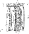
- FIG. 2 the radially outward surface of the case 110 is shown. Accordingly, a radially outward end of a vane stem 134 protrudes from the vane stem slots 112 defined in the case 110, and this radially outward end of the vane stem 134 is coupled to a vane arm 140, according to various embodiments.
- the vane arm 140 may include a first end 141 and a second end 142. The radially outward end of the vane stem 134 may be coupled to the first end 141, and a radially extending pin 150 may be coupled to the second end 142.
- the vane arm 140 extends substantially perpendicular to the vane stem 134 (e.g., perpendicular to the radial direction).
- the pin 150 extends radially through one of the plurality of cylindrical bores 125 that is jointly formed by the first and second ring portions 121, 122.
- first and second ring portions 121, 122 are detachably coupled together (e.g., via bolts), these ring portions 121, 122 may be disconnected from each other to allow more freedom during assembly of the gas turbine engine 20, as described in greater detail below with reference to FIGS. 6 , 7A , 7B , 7C , 7D , 7E , and 7F .
- the first end 141 of the vane arm 140 has a dovetail-type cavity 146, and the radially outward end of the vane stem 134 includes a complementary dovetail-type protrusion 136.
- the engagement between the first end 141 of the vane arm 140 and the vane stem 134 may be configured to reinforce against radial movement of the vane.
- the dovetail-type connection may prevent the vane from moving radially relative to the vane arm 140.
- coupling the first end 141 of the vane arm 140 to the radially outward end of the vane stem 134 may involve axial movement between the vane arm 140 and the vane stem 134 (i.e., coupling the first end 141 of the vane arm 140 to the vane stem 134 may include inserting the dovetail-type protrusion 136 in an axial direction into the dovetail-type cavity 146).
- the position of the vane arms 140 may be individually adjusted, thus improving the ease of assembly and repair.
- the first ring portion 121 may be detached from the second ring portion 122, thus allowing individual vane arms 140 to be axially moved and adjusted to individually engage the vane arms 140 to respective vane stems 134.
- the pin 150 is at least one of rotatably coupled to the second end 142 of the vane arm 140 or rotatable within the one of the plurality of cylindrical bores 125. Said differently, the pin 150 may be coupled in rotatable engagement with the second end 142 of the vane arm 140 and/or the pin 150 may extend through a cylindrical bore 125 jointly formed by the first and second ring portions 121, 122. In various embodiments, the pin 150 may be preassembled attached to the vane arm 140 (i.e., the pin 150 may be permanently coupled to the vane arm 140, such that separating the pin 150 from the vane arm 140 would damage at least one of the pin 150 or the vane arm 140). Additional details pertaining to methods of assembly and repair are included below with reference to FIGS. 6 , 7A , 7B , 7C , 7D , 7E , and 7F .
- the ring portions 121, 122 of the synchronization ring 120 are formed of a plurality of arcuate segments.
- the first ring portion 121 may include a plurality of first arcuate segments 121A, 121B that are circumferentially coupled together.
- the ring portions 121, 122 may include a clevis 119 that mechanically links arcuate segments 121A, 121B together.
- the ring portions 121, 122 may also include attachment interfaces 118, such as bolt holes or the like, for axially connecting the ring portions 121, 122 together.
- the second ring portion 122 may also include a plurality of second arcuate segments 122A, 122B, 122C, 122D that are circumferentially coupled together.
- a first interface/joint between first adjacent arcuate segments of the plurality of first arcuate segments 121A, 121B is configured to be circumferentially misaligned with a second interface/joint between second adjacent arcuate segments of the plurality of second arcuate segments 122A, 122B.
- the first ring portion 121 is comprised of a first quantity of first arcuate segments 121A, 121B
- the second ring portion 122 is comprised of a second quantity of second arcuate segments 122A, 122B, 122C, 122D.
- the first quantity is different than the second quantity.
- the first quantity may be less than the second quantity (i.e., the second ring portion 122 or aft ring portion may be divided into more arcuate segments than the first ring portion 121).
- a method 690 of assembling the gas turbine engine 20 includes inserting the vane stem 134 through the vane stem slot 112 of the case 110 at step 691, according to various embodiments.
- the method 690 may further include coupling the vane arm 140 (e.g., the first end 141 of the vane arm 140) to a radially outward end of the vane stem 134 at step 692 and positioning the first and second ring portions 121, 122 at steps 693 and 694 respectively.
- the first ring portion 121 which may be a forward ring portion, may be positioned forward of the pin 150 at step 693
- the second ring portion 122 which may be an aft ring portion, may be positioned aft of the pin 150 at step 694.
- the method 690 may further include coupling the first ring portion 121 to the second ring portion 122 to jointly define the cylindrical bore 125 around the pin 150.
- steps 692 and 693 of the method 690 of assembling the gas turbine engine 20 include coupling several (of many) vane arms 140A, 140B, 140C to respective vane stems and positioning the first/forward ring portion 121E forward of the pins 150.
- the remaining vane arms 140 are coupled to respective vane stems.
- the vane arms 140 can be individually moved axially, thus allowing axial engagement features, such as the aforementioned dovetail-type protrusion 136 and dovetail-type cavity 146, to be individually axially engaged.
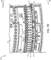
- some of the vane arms may include pins 151 that extend radially outward (i.e., away from the case 110). These outwardly extending pins 151 are described in greater detail below with reference to FIG. 7D .
- steps 694 and 695 of the method 690 include positioning the second/aft ring portion 122E aft of the pins 150 and coupling the forward ring portion 121E to the aft ring portion 122E.
- one or more additional components may be disposed between the two ring portions 121E, 122E.
- a bracket 160A that facilitates engagement of the synchronization ring 120 with the radially outward surface of the case 110 may be mounted between the two ring portions 121E, 122E.
- an actuator interface 160B may be similarly disposed between the two ring portions 121E, 122E.
- the actuator interface 160B may be a location where the drive actuator of the variable vane assembly 100 mechanically links to the synchronization ring 120 for driving rotation of the synchronization ring 120 about the case 110.
- the forward and aft ring portions 121E, 122E may be comprised of multiple arcuate segments. Accordingly, the method of assembling the gas turbine engine may further include individual positioning arcuate sections of the ring portions relative to the pins. Said differently, and with reference to FIG. 7D , arcuate segment 122F may be a section of the aft ring portion and may be positioned aft of the radially outward extending pins 151. Similarly, and with reference to FIG. 7F , arcuate segment 121F may be a section of the forward ring portion and may be positioned forward of the radially outward extending pins 151.
- the method 690 may include coupling a first section of the case 110A to a second section of the case 110B.
- the case 110 may be formed in two halves, and thus vane stems 134 of the vanes may be inserted through the vane stem slots 112 while the two halves 110A, 110B of the case 110 are separate. After the vanes are coupled to the vane arms 140, the halves 110A, 110B of the case may be coupled together.
- the method 690 further includes individually removing a vane to be replaced or repaired.
- Individually removing the vane includes decoupling at least a local arcuate segment of the aft ring portion from the first ring portion and decoupling the first end of the vane arm from the radially outward end of the vane stem via relative axial movement between the vane arm and the radially outward end of the vane stem, according to various embodiments.
- any of the method or process descriptions may be executed in any order and are not necessarily limited to the order presented.
- any reference to singular includes plural embodiments, and any reference to more than one component or step may include a singular embodiment or step.
- Elements and steps in the figures are illustrated for simplicity and clarity and have not necessarily been rendered according to any particular sequence. For example, steps that may be performed concurrently or in different order are illustrated in the figures to help to improve understanding of embodiments of the present disclosure.
- Any reference to attached, fixed, connected or the like may include permanent, removable, temporary, partial, full and/or any other possible attachment option. Additionally, any reference to without contact (or similar phrases) may also include reduced contact or minimal contact. Surface shading lines may be used throughout the figures to denote different parts or areas but not necessarily to denote the same or different materials. In some cases, reference coordinates may be specific to each figure.
- references to "one embodiment,” “an embodiment,” “various embodiments,” etc. indicate that the embodiment described may include a particular feature, structure, or characteristic, but every embodiment may not necessarily include the particular feature, structure, or characteristic. Moreover, such phrases are not necessarily referring to the same embodiment. Further, when a particular feature, structure, or characteristic is described in connection with an embodiment, it is submitted that it is within the knowledge of one skilled in the art to affect such feature, structure, or characteristic in connection with other embodiments whether or not explicitly described. After reading the description, it will be apparent to one skilled in the relevant art(s) how to implement the disclosure in alternative embodiments.
Landscapes
- Engineering & Computer Science (AREA)
- Mechanical Engineering (AREA)
- General Engineering & Computer Science (AREA)
- Turbine Rotor Nozzle Sealing (AREA)
Applications Claiming Priority (1)
| Application Number | Priority Date | Filing Date | Title |
|---|---|---|---|
| US15/630,650 US10526911B2 (en) | 2017-06-22 | 2017-06-22 | Split synchronization ring for variable vane assembly |
Publications (3)
| Publication Number | Publication Date |
|---|---|
| EP3418503A2 true EP3418503A2 (de) | 2018-12-26 |
| EP3418503A3 EP3418503A3 (de) | 2019-03-06 |
| EP3418503B1 EP3418503B1 (de) | 2020-04-15 |
Family
ID=62027878
Family Applications (1)
| Application Number | Title | Priority Date | Filing Date |
|---|---|---|---|
| EP18168256.8A Active EP3418503B1 (de) | 2017-06-22 | 2018-04-19 | Geteilter synchronisationsring für variable schaufelanordnung |
Country Status (2)
| Country | Link |
|---|---|
| US (1) | US10526911B2 (de) |
| EP (1) | EP3418503B1 (de) |
Families Citing this family (6)
| Publication number | Priority date | Publication date | Assignee | Title |
|---|---|---|---|---|
| DE102017222209A1 (de) * | 2017-12-07 | 2019-06-13 | MTU Aero Engines AG | Leitschaufelanbindung sowie Strömungsmaschine |
| BE1026411B1 (fr) * | 2018-06-21 | 2020-01-30 | Safran Aero Boosters Sa | Virole extérieure de turbomachine |
| FR3107319B1 (fr) * | 2020-02-19 | 2022-08-12 | Safran Aircraft Engines | Module de turbomachine equipe de systeme de changement de pas des pales d’aubes de stator |
| PL437817A1 (pl) | 2021-05-07 | 2022-11-14 | General Electric Company | Układ o zmiennej geometrii i działaniu rozdzielonym do sprężarki silnika turbinowego |
| FR3133367B1 (fr) * | 2022-03-11 | 2024-08-23 | Safran Aircraft Engines | Propulseur aeronautique |
| CN117006097A (zh) * | 2022-04-29 | 2023-11-07 | 中国科学院工程热物理研究所 | 叶片调节机构及压气机 |
Family Cites Families (33)
| Publication number | Priority date | Publication date | Assignee | Title |
|---|---|---|---|---|
| US3314654A (en) * | 1965-07-30 | 1967-04-18 | Gen Electric | Variable area turbine nozzle for axial flow gas turbine engines |
| US3608860A (en) * | 1969-11-12 | 1971-09-28 | Allis Chalmers Mfg Co | Wicket-gate-restraining device |
| FR2608678B1 (fr) * | 1986-12-17 | 1991-02-08 | Snecma | Dispositif de commande d'aubes a calage variable de redresseur de turbomachine |
| US4792277A (en) * | 1987-07-08 | 1988-12-20 | United Technologies Corporation | Split shroud compressor |
| US4834613A (en) * | 1988-02-26 | 1989-05-30 | United Technologies Corporation | Radially constrained variable vane shroud |
| FR2644525B1 (fr) * | 1989-03-15 | 1991-05-24 | Snecma | Systeme de retention d'aubes de stator a calage variable |
| US4990056A (en) | 1989-11-16 | 1991-02-05 | General Motors Corporation | Stator vane stage in axial flow compressor |
| FR2682157B1 (fr) * | 1991-10-02 | 1995-01-20 | Snecma | Biellette de commande d'aube et reseau de telles biellettes. |
| FR2707338B1 (fr) * | 1993-07-07 | 1995-08-11 | Snecma | Aube de turbomachine à cambrure variable. |
| US5421703A (en) * | 1994-05-25 | 1995-06-06 | General Electric Company | Positively retained vane bushing for an axial flow compressor |
| US6086327A (en) * | 1999-01-20 | 2000-07-11 | Mack Plastics Corporation | Bushing for a jet engine vane |
| DE10161292A1 (de) * | 2001-12-13 | 2003-06-26 | Rolls Royce Deutschland | Lagerring zur Lagerung von Schaufelfüßen von verstellbaren Statorschaufeln im Hochdruckverdichter einer Gasturbine |
| US6984104B2 (en) | 2002-12-16 | 2006-01-10 | United Technologies Corporation | Variable vane arm/unison ring attachment system |
| GB2412946A (en) | 2004-04-06 | 2005-10-12 | Rolls Royce Plc | A unison ring |
| FR2882570B1 (fr) * | 2005-02-25 | 2007-04-13 | Snecma Moteurs Sa | Dipositif de commande d'aubes a calage variable dans une turbomachine |
| US7588415B2 (en) | 2005-07-20 | 2009-09-15 | United Technologies Corporation | Synch ring variable vane synchronizing mechanism for inner diameter vane shroud |
| US7510369B2 (en) * | 2005-09-02 | 2009-03-31 | United Technologies Corporation | Sacrificial inner shroud liners for gas turbine engines |
| FR2902454A1 (fr) | 2006-06-16 | 2007-12-21 | Snecma Sa | Stator de turbomachine comportant un etage d'aubes de redresseurs actionnees par une couronne rotative a centrage automatique |
| US7713022B2 (en) * | 2007-03-06 | 2010-05-11 | United Technologies Operations | Small radial profile shroud for variable vane structure in a gas turbine engine |
| FR2922257B1 (fr) | 2007-10-12 | 2014-03-28 | Snecma | Perfectionnement a un anneau de commande de calage des aubes fixes d'une turbomachine |
| US8500394B2 (en) * | 2008-02-20 | 2013-08-06 | United Technologies Corporation | Single channel inner diameter shroud with lightweight inner core |
| US8328512B2 (en) * | 2009-06-05 | 2012-12-11 | United Technologies Corporation | Inner diameter shroud assembly for variable inlet guide vane structure in a gas turbine engine |
| US8668443B2 (en) | 2010-01-08 | 2014-03-11 | Honeywell International Inc. | Variable-vane assembly having unison ring guided radially by rollers and fixed members, and restrained axially by one or more fixed axial stops |
| US20110176913A1 (en) * | 2010-01-19 | 2011-07-21 | Stephen Paul Wassynger | Non-linear asymmetric variable guide vane schedule |
| FR2963384B1 (fr) * | 2010-07-30 | 2012-08-31 | Turbomeca | Dispositif de commande d'aubes pivotantes de turbomachine |
| US9422825B2 (en) | 2012-11-05 | 2016-08-23 | United Technologies Corporation | Gas turbine engine synchronization ring |
| WO2014143445A2 (en) * | 2013-02-10 | 2014-09-18 | United Technologies Corporation | Variable vane overlap shroud |
| US9932988B2 (en) * | 2013-02-15 | 2018-04-03 | United Technologies Corporation | Bushing arranged between a body and a shaft, and connected to the shaft |
| EP2971597B1 (de) | 2013-03-13 | 2021-12-29 | Raytheon Technologies Corporation | Maschinenschaufelarm eines variablen schaufelverstellsystems |
| FR3009335B1 (fr) * | 2013-07-30 | 2015-09-04 | Snecma | Dispositif de guidage d'aubes de redresseur a angle de calage variable de turbomachine |
| EP3039252B1 (de) * | 2013-08-28 | 2024-09-25 | RTX Corporation | Buchse für verstellbare leitschaufel |
| JP6543689B2 (ja) | 2014-07-16 | 2019-07-10 | ボーグワーナー インコーポレーテッド | 可変型タービン幾何学的形態のターボチャージャー用調節リング組立体 |
| FR3027635B1 (fr) * | 2014-10-27 | 2016-11-04 | Snecma | Systeme de commande d'aubes a calage variable pour une turbomachine |
-
2017
- 2017-06-22 US US15/630,650 patent/US10526911B2/en active Active
-
2018
- 2018-04-19 EP EP18168256.8A patent/EP3418503B1/de active Active
Non-Patent Citations (1)
| Title |
|---|
| None |
Also Published As
| Publication number | Publication date |
|---|---|
| US20180371937A1 (en) | 2018-12-27 |
| EP3418503B1 (de) | 2020-04-15 |
| EP3418503A3 (de) | 2019-03-06 |
| US10526911B2 (en) | 2020-01-07 |
Similar Documents
| Publication | Publication Date | Title |
|---|---|---|
| EP3418503B1 (de) | Geteilter synchronisationsring für variable schaufelanordnung | |
| EP2900956B1 (de) | Gasturbinentriebwerk mit einer dichtungsanordnung für eine statische struktur | |
| EP3670860B1 (de) | Bläser und niederdruckverdichter, die an die niedergeschwindigkeitsspule einer gasturbine gekoppelt sind | |
| US9915163B2 (en) | Cam-follower active clearance control | |
| CA2881861C (en) | Fan drive gear system module and inlet guide vane coupling mechanism | |
| EP3258073B1 (de) | Aktiv-kernkühlsystem | |
| US10837635B2 (en) | Fuel swirler with anti-rotation features | |
| US10208610B2 (en) | Ring seal arrangement | |
| EP3392461B1 (de) | Gasturbinentriebwerk und verfahren zum zusammenbauen eines solchen gasturbinentriebwerkes | |
| US10202858B2 (en) | Reconfiguring a stator vane structure of a turbine engine | |
| US12049904B2 (en) | Tandem blade rotor disk | |
| EP3477046B1 (de) | Verdrehsicherungsanordnung für zwei gekoppelte wellen, gasturbinenmotor und zugehöriges montageverfahren für einen gasturbinenmotor | |
| EP3677837B1 (de) | Brennkammerkühlplatte mit strömungsführung | |
| EP3453836B1 (de) | Leitschaufelträger mit verdrehsicherung | |
| US10408088B2 (en) | Mid-turbine frame stator with repairable bushing and retention pin |
Legal Events
| Date | Code | Title | Description |
|---|---|---|---|
| PUAI | Public reference made under article 153(3) epc to a published international application that has entered the european phase |
Free format text: ORIGINAL CODE: 0009012 |
|
| STAA | Information on the status of an ep patent application or granted ep patent |
Free format text: STATUS: THE APPLICATION HAS BEEN PUBLISHED |
|
| AK | Designated contracting states |
Kind code of ref document: A2 Designated state(s): AL AT BE BG CH CY CZ DE DK EE ES FI FR GB GR HR HU IE IS IT LI LT LU LV MC MK MT NL NO PL PT RO RS SE SI SK SM TR |
|
| AX | Request for extension of the european patent |
Extension state: BA ME |
|
| PUAL | Search report despatched |
Free format text: ORIGINAL CODE: 0009013 |
|
| AK | Designated contracting states |
Kind code of ref document: A3 Designated state(s): AL AT BE BG CH CY CZ DE DK EE ES FI FR GB GR HR HU IE IS IT LI LT LU LV MC MK MT NL NO PL PT RO RS SE SI SK SM TR |
|
| AX | Request for extension of the european patent |
Extension state: BA ME |
|
| RIC1 | Information provided on ipc code assigned before grant |
Ipc: F01D 17/16 20060101AFI20190129BHEP |
|
| RIC1 | Information provided on ipc code assigned before grant |
Ipc: F01D 17/16 20060101AFI20190211BHEP |
|
| STAA | Information on the status of an ep patent application or granted ep patent |
Free format text: STATUS: REQUEST FOR EXAMINATION WAS MADE |
|
| 17P | Request for examination filed |
Effective date: 20190906 |
|
| RBV | Designated contracting states (corrected) |
Designated state(s): AL AT BE BG CH CY CZ DE DK EE ES FI FR GB GR HR HU IE IS IT LI LT LU LV MC MK MT NL NO PL PT RO RS SE SI SK SM TR |
|
| GRAP | Despatch of communication of intention to grant a patent |
Free format text: ORIGINAL CODE: EPIDOSNIGR1 |
|
| STAA | Information on the status of an ep patent application or granted ep patent |
Free format text: STATUS: GRANT OF PATENT IS INTENDED |
|
| INTG | Intention to grant announced |
Effective date: 20191107 |
|
| GRAS | Grant fee paid |
Free format text: ORIGINAL CODE: EPIDOSNIGR3 |
|
| GRAA | (expected) grant |
Free format text: ORIGINAL CODE: 0009210 |
|
| STAA | Information on the status of an ep patent application or granted ep patent |
Free format text: STATUS: THE PATENT HAS BEEN GRANTED |
|
| AK | Designated contracting states |
Kind code of ref document: B1 Designated state(s): AL AT BE BG CH CY CZ DE DK EE ES FI FR GB GR HR HU IE IS IT LI LT LU LV MC MK MT NL NO PL PT RO RS SE SI SK SM TR |
|
| REG | Reference to a national code |
Ref country code: CH Ref legal event code: EP |
|
| REG | Reference to a national code |
Ref country code: DE Ref legal event code: R096 Ref document number: 602018003700 Country of ref document: DE |
|
| REG | Reference to a national code |
Ref country code: IE Ref legal event code: FG4D |
|
| REG | Reference to a national code |
Ref country code: AT Ref legal event code: REF Ref document number: 1257527 Country of ref document: AT Kind code of ref document: T Effective date: 20200515 |
|
| REG | Reference to a national code |
Ref country code: NL Ref legal event code: MP Effective date: 20200415 |
|
| REG | Reference to a national code |
Ref country code: LT Ref legal event code: MG4D |
|
| PG25 | Lapsed in a contracting state [announced via postgrant information from national office to epo] |
Ref country code: SE Free format text: LAPSE BECAUSE OF FAILURE TO SUBMIT A TRANSLATION OF THE DESCRIPTION OR TO PAY THE FEE WITHIN THE PRESCRIBED TIME-LIMIT Effective date: 20200415 Ref country code: LT Free format text: LAPSE BECAUSE OF FAILURE TO SUBMIT A TRANSLATION OF THE DESCRIPTION OR TO PAY THE FEE WITHIN THE PRESCRIBED TIME-LIMIT Effective date: 20200415 Ref country code: NL Free format text: LAPSE BECAUSE OF FAILURE TO SUBMIT A TRANSLATION OF THE DESCRIPTION OR TO PAY THE FEE WITHIN THE PRESCRIBED TIME-LIMIT Effective date: 20200415 Ref country code: PT Free format text: LAPSE BECAUSE OF FAILURE TO SUBMIT A TRANSLATION OF THE DESCRIPTION OR TO PAY THE FEE WITHIN THE PRESCRIBED TIME-LIMIT Effective date: 20200817 Ref country code: IS Free format text: LAPSE BECAUSE OF FAILURE TO SUBMIT A TRANSLATION OF THE DESCRIPTION OR TO PAY THE FEE WITHIN THE PRESCRIBED TIME-LIMIT Effective date: 20200815 Ref country code: FI Free format text: LAPSE BECAUSE OF FAILURE TO SUBMIT A TRANSLATION OF THE DESCRIPTION OR TO PAY THE FEE WITHIN THE PRESCRIBED TIME-LIMIT Effective date: 20200415 Ref country code: NO Free format text: LAPSE BECAUSE OF FAILURE TO SUBMIT A TRANSLATION OF THE DESCRIPTION OR TO PAY THE FEE WITHIN THE PRESCRIBED TIME-LIMIT Effective date: 20200715 Ref country code: GR Free format text: LAPSE BECAUSE OF FAILURE TO SUBMIT A TRANSLATION OF THE DESCRIPTION OR TO PAY THE FEE WITHIN THE PRESCRIBED TIME-LIMIT Effective date: 20200716 |
|
| REG | Reference to a national code |
Ref country code: AT Ref legal event code: MK05 Ref document number: 1257527 Country of ref document: AT Kind code of ref document: T Effective date: 20200415 |
|
| PG25 | Lapsed in a contracting state [announced via postgrant information from national office to epo] |
Ref country code: LV Free format text: LAPSE BECAUSE OF FAILURE TO SUBMIT A TRANSLATION OF THE DESCRIPTION OR TO PAY THE FEE WITHIN THE PRESCRIBED TIME-LIMIT Effective date: 20200415 Ref country code: RS Free format text: LAPSE BECAUSE OF FAILURE TO SUBMIT A TRANSLATION OF THE DESCRIPTION OR TO PAY THE FEE WITHIN THE PRESCRIBED TIME-LIMIT Effective date: 20200415 Ref country code: BG Free format text: LAPSE BECAUSE OF FAILURE TO SUBMIT A TRANSLATION OF THE DESCRIPTION OR TO PAY THE FEE WITHIN THE PRESCRIBED TIME-LIMIT Effective date: 20200715 Ref country code: HR Free format text: LAPSE BECAUSE OF FAILURE TO SUBMIT A TRANSLATION OF THE DESCRIPTION OR TO PAY THE FEE WITHIN THE PRESCRIBED TIME-LIMIT Effective date: 20200415 |
|
| PG25 | Lapsed in a contracting state [announced via postgrant information from national office to epo] |
Ref country code: AL Free format text: LAPSE BECAUSE OF FAILURE TO SUBMIT A TRANSLATION OF THE DESCRIPTION OR TO PAY THE FEE WITHIN THE PRESCRIBED TIME-LIMIT Effective date: 20200415 |
|
| REG | Reference to a national code |
Ref country code: DE Ref legal event code: R097 Ref document number: 602018003700 Country of ref document: DE |
|
| PG25 | Lapsed in a contracting state [announced via postgrant information from national office to epo] |
Ref country code: RO Free format text: LAPSE BECAUSE OF FAILURE TO SUBMIT A TRANSLATION OF THE DESCRIPTION OR TO PAY THE FEE WITHIN THE PRESCRIBED TIME-LIMIT Effective date: 20200415 Ref country code: CZ Free format text: LAPSE BECAUSE OF FAILURE TO SUBMIT A TRANSLATION OF THE DESCRIPTION OR TO PAY THE FEE WITHIN THE PRESCRIBED TIME-LIMIT Effective date: 20200415 Ref country code: IT Free format text: LAPSE BECAUSE OF FAILURE TO SUBMIT A TRANSLATION OF THE DESCRIPTION OR TO PAY THE FEE WITHIN THE PRESCRIBED TIME-LIMIT Effective date: 20200415 Ref country code: SM Free format text: LAPSE BECAUSE OF FAILURE TO SUBMIT A TRANSLATION OF THE DESCRIPTION OR TO PAY THE FEE WITHIN THE PRESCRIBED TIME-LIMIT Effective date: 20200415 Ref country code: EE Free format text: LAPSE BECAUSE OF FAILURE TO SUBMIT A TRANSLATION OF THE DESCRIPTION OR TO PAY THE FEE WITHIN THE PRESCRIBED TIME-LIMIT Effective date: 20200415 Ref country code: AT Free format text: LAPSE BECAUSE OF FAILURE TO SUBMIT A TRANSLATION OF THE DESCRIPTION OR TO PAY THE FEE WITHIN THE PRESCRIBED TIME-LIMIT Effective date: 20200415 Ref country code: ES Free format text: LAPSE BECAUSE OF FAILURE TO SUBMIT A TRANSLATION OF THE DESCRIPTION OR TO PAY THE FEE WITHIN THE PRESCRIBED TIME-LIMIT Effective date: 20200415 Ref country code: LU Free format text: LAPSE BECAUSE OF NON-PAYMENT OF DUE FEES Effective date: 20200419 Ref country code: DK Free format text: LAPSE BECAUSE OF FAILURE TO SUBMIT A TRANSLATION OF THE DESCRIPTION OR TO PAY THE FEE WITHIN THE PRESCRIBED TIME-LIMIT Effective date: 20200415 Ref country code: MC Free format text: LAPSE BECAUSE OF FAILURE TO SUBMIT A TRANSLATION OF THE DESCRIPTION OR TO PAY THE FEE WITHIN THE PRESCRIBED TIME-LIMIT Effective date: 20200415 |
|
| REG | Reference to a national code |
Ref country code: BE Ref legal event code: MM Effective date: 20200430 |
|
| PLBE | No opposition filed within time limit |
Free format text: ORIGINAL CODE: 0009261 |
|
| STAA | Information on the status of an ep patent application or granted ep patent |
Free format text: STATUS: NO OPPOSITION FILED WITHIN TIME LIMIT |
|
| PG25 | Lapsed in a contracting state [announced via postgrant information from national office to epo] |
Ref country code: SK Free format text: LAPSE BECAUSE OF FAILURE TO SUBMIT A TRANSLATION OF THE DESCRIPTION OR TO PAY THE FEE WITHIN THE PRESCRIBED TIME-LIMIT Effective date: 20200415 Ref country code: PL Free format text: LAPSE BECAUSE OF FAILURE TO SUBMIT A TRANSLATION OF THE DESCRIPTION OR TO PAY THE FEE WITHIN THE PRESCRIBED TIME-LIMIT Effective date: 20200415 Ref country code: BE Free format text: LAPSE BECAUSE OF NON-PAYMENT OF DUE FEES Effective date: 20200430 |
|
| 26N | No opposition filed |
Effective date: 20210118 |
|
| PG25 | Lapsed in a contracting state [announced via postgrant information from national office to epo] |
Ref country code: IE Free format text: LAPSE BECAUSE OF NON-PAYMENT OF DUE FEES Effective date: 20200419 |
|
| PG25 | Lapsed in a contracting state [announced via postgrant information from national office to epo] |
Ref country code: SI Free format text: LAPSE BECAUSE OF FAILURE TO SUBMIT A TRANSLATION OF THE DESCRIPTION OR TO PAY THE FEE WITHIN THE PRESCRIBED TIME-LIMIT Effective date: 20200415 |
|
| PG25 | Lapsed in a contracting state [announced via postgrant information from national office to epo] |
Ref country code: CH Free format text: LAPSE BECAUSE OF NON-PAYMENT OF DUE FEES Effective date: 20210430 Ref country code: LI Free format text: LAPSE BECAUSE OF NON-PAYMENT OF DUE FEES Effective date: 20210430 |
|
| PG25 | Lapsed in a contracting state [announced via postgrant information from national office to epo] |
Ref country code: TR Free format text: LAPSE BECAUSE OF FAILURE TO SUBMIT A TRANSLATION OF THE DESCRIPTION OR TO PAY THE FEE WITHIN THE PRESCRIBED TIME-LIMIT Effective date: 20200415 Ref country code: MT Free format text: LAPSE BECAUSE OF FAILURE TO SUBMIT A TRANSLATION OF THE DESCRIPTION OR TO PAY THE FEE WITHIN THE PRESCRIBED TIME-LIMIT Effective date: 20200415 Ref country code: CY Free format text: LAPSE BECAUSE OF FAILURE TO SUBMIT A TRANSLATION OF THE DESCRIPTION OR TO PAY THE FEE WITHIN THE PRESCRIBED TIME-LIMIT Effective date: 20200415 |
|
| PG25 | Lapsed in a contracting state [announced via postgrant information from national office to epo] |
Ref country code: MK Free format text: LAPSE BECAUSE OF FAILURE TO SUBMIT A TRANSLATION OF THE DESCRIPTION OR TO PAY THE FEE WITHIN THE PRESCRIBED TIME-LIMIT Effective date: 20200415 |
|
| REG | Reference to a national code |
Ref country code: DE Ref legal event code: R081 Ref document number: 602018003700 Country of ref document: DE Owner name: RAYTHEON TECHNOLOGIES CORPORATION (N.D.GES.D.S, US Free format text: FORMER OWNER: UNITED TECHNOLOGIES CORPORATION, FARMINGTON, CONN., US Ref country code: DE Ref legal event code: R081 Ref document number: 602018003700 Country of ref document: DE Owner name: RTX CORPORATION (N.D.GES.D. STAATES DELAWARE),, US Free format text: FORMER OWNER: UNITED TECHNOLOGIES CORPORATION, FARMINGTON, CONN., US |
|
| P01 | Opt-out of the competence of the unified patent court (upc) registered |
Effective date: 20230521 |
|
| PGFP | Annual fee paid to national office [announced via postgrant information from national office to epo] |
Ref country code: DE Payment date: 20250319 Year of fee payment: 8 |
|
| REG | Reference to a national code |
Ref country code: DE Ref legal event code: R081 Ref document number: 602018003700 Country of ref document: DE Owner name: RTX CORPORATION (N.D.GES.D. STAATES DELAWARE),, US Free format text: FORMER OWNER: RAYTHEON TECHNOLOGIES CORPORATION (N.D.GES.D.STAATES DELAWARE), ARLINGTON, VA, US |
|
| PGFP | Annual fee paid to national office [announced via postgrant information from national office to epo] |
Ref country code: GB Payment date: 20260319 Year of fee payment: 9 |
|
| PGFP | Annual fee paid to national office [announced via postgrant information from national office to epo] |
Ref country code: FR Payment date: 20260320 Year of fee payment: 9 |