EP3677837B1 - Brennkammerkühlplatte mit strömungsführung - Google Patents
Brennkammerkühlplatte mit strömungsführung Download PDFInfo
- Publication number
- EP3677837B1 EP3677837B1 EP20150392.7A EP20150392A EP3677837B1 EP 3677837 B1 EP3677837 B1 EP 3677837B1 EP 20150392 A EP20150392 A EP 20150392A EP 3677837 B1 EP3677837 B1 EP 3677837B1
- Authority
- EP
- European Patent Office
- Prior art keywords
- panel
- flow guide
- shell
- combustor
- section
- Prior art date
- Legal status (The legal status is an assumption and is not a legal conclusion. Google has not performed a legal analysis and makes no representation as to the accuracy of the status listed.)
- Active
Links
- 238000001816 cooling Methods 0.000 title description 6
- 239000000446 fuel Substances 0.000 claims description 21
- 238000002485 combustion reaction Methods 0.000 claims description 13
- 239000012809 cooling fluid Substances 0.000 claims description 3
- 238000004891 communication Methods 0.000 claims description 2
- 230000001154 acute effect Effects 0.000 claims 1
- 238000000034 method Methods 0.000 description 7
- 230000008901 benefit Effects 0.000 description 6
- 239000000203 mixture Substances 0.000 description 3
- 230000008569 process Effects 0.000 description 3
- 239000000463 material Substances 0.000 description 2
- 230000003068 static effect Effects 0.000 description 2
- 230000003416 augmentation Effects 0.000 description 1
- 230000006835 compression Effects 0.000 description 1
- 238000007906 compression Methods 0.000 description 1
- 230000008878 coupling Effects 0.000 description 1
- 238000010168 coupling process Methods 0.000 description 1
- 238000005859 coupling reaction Methods 0.000 description 1
- 230000001419 dependent effect Effects 0.000 description 1
- 230000009467 reduction Effects 0.000 description 1
- 230000004044 response Effects 0.000 description 1
- 239000000126 substance Substances 0.000 description 1
Images


Classifications
-
- F—MECHANICAL ENGINEERING; LIGHTING; HEATING; WEAPONS; BLASTING
- F23—COMBUSTION APPARATUS; COMBUSTION PROCESSES
- F23R—GENERATING COMBUSTION PRODUCTS OF HIGH PRESSURE OR HIGH VELOCITY, e.g. GAS-TURBINE COMBUSTION CHAMBERS
- F23R3/00—Continuous combustion chambers using liquid or gaseous fuel
- F23R3/005—Combined with pressure or heat exchangers
-
- F—MECHANICAL ENGINEERING; LIGHTING; HEATING; WEAPONS; BLASTING
- F23—COMBUSTION APPARATUS; COMBUSTION PROCESSES
- F23R—GENERATING COMBUSTION PRODUCTS OF HIGH PRESSURE OR HIGH VELOCITY, e.g. GAS-TURBINE COMBUSTION CHAMBERS
- F23R3/00—Continuous combustion chambers using liquid or gaseous fuel
- F23R3/002—Wall structures
-
- F—MECHANICAL ENGINEERING; LIGHTING; HEATING; WEAPONS; BLASTING
- F23—COMBUSTION APPARATUS; COMBUSTION PROCESSES
- F23R—GENERATING COMBUSTION PRODUCTS OF HIGH PRESSURE OR HIGH VELOCITY, e.g. GAS-TURBINE COMBUSTION CHAMBERS
- F23R3/00—Continuous combustion chambers using liquid or gaseous fuel
- F23R3/02—Continuous combustion chambers using liquid or gaseous fuel characterised by the air-flow or gas-flow configuration
- F23R3/04—Air inlet arrangements
- F23R3/06—Arrangement of apertures along the flame tube
-
- F—MECHANICAL ENGINEERING; LIGHTING; HEATING; WEAPONS; BLASTING
- F02—COMBUSTION ENGINES; HOT-GAS OR COMBUSTION-PRODUCT ENGINE PLANTS
- F02C—GAS-TURBINE PLANTS; AIR INTAKES FOR JET-PROPULSION PLANTS; CONTROLLING FUEL SUPPLY IN AIR-BREATHING JET-PROPULSION PLANTS
- F02C7/00—Features, components parts, details or accessories, not provided for in, or of interest apart form groups F02C1/00 - F02C6/00; Air intakes for jet-propulsion plants
- F02C7/12—Cooling of plants
- F02C7/16—Cooling of plants characterised by cooling medium
- F02C7/18—Cooling of plants characterised by cooling medium the medium being gaseous, e.g. air
-
- F—MECHANICAL ENGINEERING; LIGHTING; HEATING; WEAPONS; BLASTING
- F05—INDEXING SCHEMES RELATING TO ENGINES OR PUMPS IN VARIOUS SUBCLASSES OF CLASSES F01-F04
- F05D—INDEXING SCHEME FOR ASPECTS RELATING TO NON-POSITIVE-DISPLACEMENT MACHINES OR ENGINES, GAS-TURBINES OR JET-PROPULSION PLANTS
- F05D2220/00—Application
- F05D2220/30—Application in turbines
- F05D2220/32—Application in turbines in gas turbines
- F05D2220/323—Application in turbines in gas turbines for aircraft propulsion, e.g. jet engines
-
- F—MECHANICAL ENGINEERING; LIGHTING; HEATING; WEAPONS; BLASTING
- F05—INDEXING SCHEMES RELATING TO ENGINES OR PUMPS IN VARIOUS SUBCLASSES OF CLASSES F01-F04
- F05D—INDEXING SCHEME FOR ASPECTS RELATING TO NON-POSITIVE-DISPLACEMENT MACHINES OR ENGINES, GAS-TURBINES OR JET-PROPULSION PLANTS
- F05D2240/00—Components
- F05D2240/35—Combustors or associated equipment
-
- F—MECHANICAL ENGINEERING; LIGHTING; HEATING; WEAPONS; BLASTING
- F05—INDEXING SCHEMES RELATING TO ENGINES OR PUMPS IN VARIOUS SUBCLASSES OF CLASSES F01-F04
- F05D—INDEXING SCHEME FOR ASPECTS RELATING TO NON-POSITIVE-DISPLACEMENT MACHINES OR ENGINES, GAS-TURBINES OR JET-PROPULSION PLANTS
- F05D2260/00—Function
- F05D2260/20—Heat transfer, e.g. cooling
- F05D2260/201—Heat transfer, e.g. cooling by impingement of a fluid
-
- F—MECHANICAL ENGINEERING; LIGHTING; HEATING; WEAPONS; BLASTING
- F05—INDEXING SCHEMES RELATING TO ENGINES OR PUMPS IN VARIOUS SUBCLASSES OF CLASSES F01-F04
- F05D—INDEXING SCHEME FOR ASPECTS RELATING TO NON-POSITIVE-DISPLACEMENT MACHINES OR ENGINES, GAS-TURBINES OR JET-PROPULSION PLANTS
- F05D2260/00—Function
- F05D2260/20—Heat transfer, e.g. cooling
- F05D2260/202—Heat transfer, e.g. cooling by film cooling
-
- F—MECHANICAL ENGINEERING; LIGHTING; HEATING; WEAPONS; BLASTING
- F23—COMBUSTION APPARATUS; COMBUSTION PROCESSES
- F23R—GENERATING COMBUSTION PRODUCTS OF HIGH PRESSURE OR HIGH VELOCITY, e.g. GAS-TURBINE COMBUSTION CHAMBERS
- F23R2900/00—Special features of, or arrangements for continuous combustion chambers; Combustion processes therefor
- F23R2900/03041—Effusion cooled combustion chamber walls or domes
-
- F—MECHANICAL ENGINEERING; LIGHTING; HEATING; WEAPONS; BLASTING
- F23—COMBUSTION APPARATUS; COMBUSTION PROCESSES
- F23R—GENERATING COMBUSTION PRODUCTS OF HIGH PRESSURE OR HIGH VELOCITY, e.g. GAS-TURBINE COMBUSTION CHAMBERS
- F23R2900/00—Special features of, or arrangements for continuous combustion chambers; Combustion processes therefor
- F23R2900/03042—Film cooled combustion chamber walls or domes
-
- F—MECHANICAL ENGINEERING; LIGHTING; HEATING; WEAPONS; BLASTING
- F23—COMBUSTION APPARATUS; COMBUSTION PROCESSES
- F23R—GENERATING COMBUSTION PRODUCTS OF HIGH PRESSURE OR HIGH VELOCITY, e.g. GAS-TURBINE COMBUSTION CHAMBERS
- F23R2900/00—Special features of, or arrangements for continuous combustion chambers; Combustion processes therefor
- F23R2900/03043—Convection cooled combustion chamber walls with means for guiding the cooling air flow
-
- F—MECHANICAL ENGINEERING; LIGHTING; HEATING; WEAPONS; BLASTING
- F23—COMBUSTION APPARATUS; COMBUSTION PROCESSES
- F23R—GENERATING COMBUSTION PRODUCTS OF HIGH PRESSURE OR HIGH VELOCITY, e.g. GAS-TURBINE COMBUSTION CHAMBERS
- F23R2900/00—Special features of, or arrangements for continuous combustion chambers; Combustion processes therefor
- F23R2900/03044—Impingement cooled combustion chamber walls or subassemblies
-
- F—MECHANICAL ENGINEERING; LIGHTING; HEATING; WEAPONS; BLASTING
- F23—COMBUSTION APPARATUS; COMBUSTION PROCESSES
- F23R—GENERATING COMBUSTION PRODUCTS OF HIGH PRESSURE OR HIGH VELOCITY, e.g. GAS-TURBINE COMBUSTION CHAMBERS
- F23R2900/00—Special features of, or arrangements for continuous combustion chambers; Combustion processes therefor
- F23R2900/03045—Convection cooled combustion chamber walls provided with turbolators or means for creating turbulences to increase cooling
-
- F—MECHANICAL ENGINEERING; LIGHTING; HEATING; WEAPONS; BLASTING
- F23—COMBUSTION APPARATUS; COMBUSTION PROCESSES
- F23R—GENERATING COMBUSTION PRODUCTS OF HIGH PRESSURE OR HIGH VELOCITY, e.g. GAS-TURBINE COMBUSTION CHAMBERS
- F23R3/00—Continuous combustion chambers using liquid or gaseous fuel
- F23R3/42—Continuous combustion chambers using liquid or gaseous fuel characterised by the arrangement or form of the flame tubes or combustion chambers
- F23R3/50—Combustion chambers comprising an annular flame tube within an annular casing
-
- F—MECHANICAL ENGINEERING; LIGHTING; HEATING; WEAPONS; BLASTING
- F23—COMBUSTION APPARATUS; COMBUSTION PROCESSES
- F23R—GENERATING COMBUSTION PRODUCTS OF HIGH PRESSURE OR HIGH VELOCITY, e.g. GAS-TURBINE COMBUSTION CHAMBERS
- F23R3/00—Continuous combustion chambers using liquid or gaseous fuel
- F23R3/42—Continuous combustion chambers using liquid or gaseous fuel characterised by the arrangement or form of the flame tubes or combustion chambers
- F23R3/60—Support structures; Attaching or mounting means
-
- Y—GENERAL TAGGING OF NEW TECHNOLOGICAL DEVELOPMENTS; GENERAL TAGGING OF CROSS-SECTIONAL TECHNOLOGIES SPANNING OVER SEVERAL SECTIONS OF THE IPC; TECHNICAL SUBJECTS COVERED BY FORMER USPC CROSS-REFERENCE ART COLLECTIONS [XRACs] AND DIGESTS
- Y02—TECHNOLOGIES OR APPLICATIONS FOR MITIGATION OR ADAPTATION AGAINST CLIMATE CHANGE
- Y02T—CLIMATE CHANGE MITIGATION TECHNOLOGIES RELATED TO TRANSPORTATION
- Y02T50/00—Aeronautics or air transport
- Y02T50/60—Efficient propulsion technologies, e.g. for aircraft
Definitions
- the present disclosure relates generally to gas turbine engines and, more particularly, to flow guides for use with a panel of a combustor section of a gas turbine engine to provide desired flow of compressed gas over the panel.
- Gas turbine engines include compressor sections to compress an airflow, combustor sections that combine the airflow with fuel for combustion and generate exhaust, and turbine sections that convert the exhaust into torque to drive the compressor sections.
- the combustor sections may include a combustor liner which may include an outer shell and an inner panel.
- the combustor liner may experience relatively great temperatures. It may be desirable to direct compressed gas across the inner panel to provide heat transfer from the panel to the compressed gas, thus cooling the panel.
- a combustor liner according to the preamble of claim 1 is described by US2003/140632 .
- a combustor liner for a gas turbine engine as set forth in claim 1.
- a gas turbine engine 20 is provided.
- “aft” refers to the direction associated with the tail (e.g., the back end) of an aircraft, or generally, to the direction of exhaust of the gas turbine engine.
- “forward” refers to the direction associated with the nose (e.g., the front end) of an aircraft, or generally, to the direction of flight or motion.
- radially inward refers to the negative R direction and radially outward refers to the R direction.
- An A-R-C axis is shown throughout the drawings to illustrate the relative position of various components.
- the gas turbine engine 20 may be a two-spool turbofan that generally incorporates a fan section 22, a compressor section 24, a combustor section 26 and a turbine section 28.
- the fan section 22 drives air along a bypass flow-path B while the compressor section 24 drives air along a core flow-path C for compression and communication into the combustor section 26 then expansion through the turbine section 28.
- a turbofan gas turbine engine 20 depicted as a turbofan gas turbine engine 20 herein, it should be understood that the concepts described herein are not limited to use with turbofans as the teachings may be applied to other types of turbine engines including three-spool architectures, geared turbofan architectures, and turboshaft or industrial gas turbines with one or more spools.
- the gas turbine engine 20 generally comprises a low speed spool 30 and a high speed spool 32 mounted for rotation about an engine central longitudinal axis X-X' relative to an engine static structure 36 via several bearing systems 38, 38-1, and 38-2. It should be understood that various bearing systems 38 at various locations may alternatively or additionally be provided, including for example, the bearing system 38, the bearing system 38-1, and the bearing system 38-2.
- the low speed spool 30 generally includes an inner shaft 40 that interconnects a fan 42, a low pressure (or first) compressor section 44 and a low pressure (or second) turbine section 46.
- the inner shaft 40 is connected to the fan 42 through a geared architecture 48 that can drive the fan shaft 98, and thus the fan 42, at a lower speed than the low speed spool 30.
- the geared architecture 48 includes a gear assembly 60 enclosed within a gear diffuser case 62.
- the gear assembly 60 couples the inner shaft 40 to a rotating fan structure.
- the high speed spool 32 includes an outer shaft 50 that interconnects a high pressure (or second) compressor section 52 and the high pressure (or first) turbine section 54.
- a combustor 56 is located between the high pressure compressor 52 and the high pressure turbine 54.
- a mid-turbine frame 57 of the engine static structure 36 is located generally between the high pressure turbine 54 and the low pressure turbine 46.
- the mid-turbine frame 57 supports one or more bearing systems 38 in the turbine section 28.
- the inner shaft 40 and the outer shaft 50 are concentric and rotate via the bearing systems 38 about the engine central longitudinal axis X-X', which is collinear with their longitudinal axes.
- a "high pressure" compressor or turbine experiences a higher pressure than a corresponding "low pressure” compressor or turbine.
- the core airflow C is compressed by the low pressure compressor section 44 then the high pressure compressor 52, mixed and burned with fuel in the combustor 56, then expanded over the high pressure turbine 54 and the low pressure turbine 46.
- the mid-turbine frame 57 includes airfoils 59 which are in the core airflow path.
- the turbines 46, 54 rotationally drive the respective low speed spool 30 and high speed spool 32 in response to the expansion.
- the gas turbine engine 20 is a high-bypass ratio geared aircraft engine.
- the bypass ratio of the gas turbine engine 20 may be greater than about six.
- the bypass ratio of the gas turbine engine 20 may also be greater than ten.
- the geared architecture 48 may be an epicyclic gear train, such as a star gear system (sun gear in meshing engagement with a plurality of star gears supported by a carrier and in meshing engagement with a ring gear) or other gear system.
- the geared architecture 48 may have a gear reduction ratio of greater than about 2.3 and the low pressure turbine 46 may have a pressure ratio that is greater than about five.
- the diameter of the fan 42 may be significantly larger than that of the low pressure compressor section 44, and the low pressure turbine 46 may have a pressure ratio that is greater than about five.
- the pressure ratio of the low pressure turbine 46 is measured prior to an inlet of the low pressure turbine 46 as related to the pressure at the outlet of the low pressure turbine 46. It should be understood, however, that the above parameters are exemplary of various embodiments of a suitable geared architecture engine and that the present disclosure contemplates other turbine engines including direct drive turbofans.
- next generation turbofan engines are designed for higher efficiency and use higher pressure ratios and higher temperatures in the high pressure compressor 52 than are conventionally experienced. These higher operating temperatures and pressure ratios create operating environments that cause thermal loads that are higher than the thermal loads conventionally experienced, which may shorten the operational life of current components.
- the combustor section 26 may include an annular combustor 132.
- the annular combustor 132 may include multiple fuel nozzles 124, which each include their own trim valve 134.
- each fuel nozzle 124 delivers fuel to a respective section of the combustion chamber 128.
- the fuel nozzles 124 may be arranged circumferentially around an axis within a combustor 132.
- the fuel nozzles 124 may include stems 136 that extend from a diffuser case 118 to openings.
- the combustor section 26 may include multiple openings circumferentially around the combustor section 26 that receive fuel nozzles 124.
- the combustor section 26 may further include a diffuser case 118.
- the diffuser case 118 surrounds or encloses a plurality of combustor liners 130.
- Various impingement jets may be used for impingement cooling of the liner 130, and effusion holes may be used for convection cooling and to build film cooling on the hot side of the liner.
- the combustor liner 130 may define a combustion chamber 128.
- a fuel source 125 provides fuel to the fuel nozzle 124 for delivery to the combustion chamber 128.
- the fuel nozzle 124 extends through an aperture 121 in the diffuser case 118.
- An end of the fuel nozzle 124 may be arranged at an inlet 126 of the combustion chamber 128.
- One or more liners 130 e.g. the bulkhead liners
- These or other liners 130 can include one or more openings to receive igniters used to begin combustion of the air/fuel mixture.
- the diffuser case 118 and the combustor liner 130 may define an outer shroud 156 and an inner shroud 154 therebetween.
- air or another compressed gas may flow through at least one of the inner shroud 154 or the outer shroud 156.
- the fuel nozzle 124 may extend through the outer shroud 156 and may be extended into the inner shroud 154.
- the inner shroud 154 and the outer shroud 156 may each be referred to as a diffuser chamber 154, 156.
- the combustor liner 130 includes a panel 150 and a shell 152.
- the panel 150 may be directly or indirectly coupled to the shell 152, for example by placing the shell 152 on stand-off pins 207 on the panel 150 then securing a fastener (not shown) to the stud 209 to retain the shell 152, to resist movement of the panel 150 relative to the shell 152.
- the panel 150 at least partially defines the combustion chamber 128, and the shell 152 may be located between the outer shroud 156 and the panel 150, or between the inner shroud 154 and the panel.
- the panel 150 and shell 152 define a cavity 211 therebetween.
- the panel 150 may have an outer surface 200 (a "cold” side) that faces towards the shell 152 and an inner surface 202 (a "hot” side) that at least partially defines the combustion chamber 128.
- the panel 150 may further include a plurality of effusion holes 220 through which a cooling fluid, such as the core engine air (i.e. compressed gas) may flow from the cavity 211 to the combustion chamber 128.
- the shell 152 may define one or more impingement holes 208 that receive a compressed gas, such as air, from the shroud 154, 156 (i.e., diffuser chamber).
- the compressed gas from the impingement hole 208 may be directed into the cavity 211 and towards the panel 150, as shown by arrows 210. Because the panel 150 is located proximate to the combustion chamber 128, the panel 150 may be subjected to relatively high temperatures. In that regard, cooling of the panel 150 may be desirable.
- the compressed gas from the impingement hole 208 may facilitate heat transfer from the panel 150 to the compressed gas, thus reducing a temperature of the panel 150.
- the compressed gas may flow through the panel swirler 214 (and/or through the effusion holes 220) to the combustion chamber 128 where it may mix with the fuel and be combusted.
- the panel 150 includes various features to increase heat transfer from the panel 150 to the compressed gas received from the impingement holes 208 in the shell 152.
- the panel 150 further includes a plurality of heat augmentors 206 extending from the outer surface 200 towards the shell 152.
- the heat augmentors 206 may have a shape that resembles a pin and may provide increased surface area of the outer surface 200 in order to increase heat transfer from the panel 150 to the compressed gas.
- the heat augmentors may include pin fins or material having other shapes that extends from the panel 150.
- the panel 150 further includes a flow guide 204 extending from the outer surface 200 towards the shell 152.
- the cross-section of the flow guide 204 is a triangle having an apex 205 oriented towards the shell 152.
- the flow guide 204 may receive the compressed gas from the impingement holes 208 as shown by the arrows 210.
- the flow guide 204 may direct the compressed gas over a portion of the outer surface 200 as shown by arrows 212, thus directing the compressed gas in a desired direction.
- the flow guide 204 may increase heat transfer from the outer surface 200 and may also increase ejection of debris.
- the flow guide 204 could be unitary with the panel 150, or a separate piece secured to the panel 150 using known techniques.
- the cross-section of the flow guide 204 may resemble an isosceles triangle or an equilateral triangle, and forms an angle 207 with the outer surface 200.
- the angle 207 may be any angle such as, for example, between 1 degree and 89 degrees, between 10 degrees and 80 degrees, between 20 degrees and 70 degrees, or the like.
- the angle 207 and shape of the flow guide 204 may be selected based on a desired amount for the flow to be turned, a desired direction of the flow, or the like.
- some or all of the impingement holes 208 may have an angle that is equal to, greater than, or less than the angle 207 of the flow guide 204.
- the flow guide 204 may further turn impingement flow to enhance and drive crossflow through the heat augmentors.
- the flow guide 204 may be referred to as a surface area augmentation to enhance heat transfer.
- the flow guide 204 may further host effusion holes.
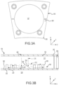
- FIG. 3B which is not part of the invention as defined by the claims, the flow guide 204 may receive the compressed gas from multiple impingement holes 208.
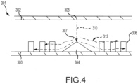
- another combustor liner 301 may include a flow guide 304 that receives compressed gas from a single impingement hole 308.
- the combustor liner 301 may include a shell 302 and a panel 300, and the panel 300 may include heat augmentors 306 extending towards the shell 302.
- the flow guide 304 may extend from the panel 300 towards the shell 302.
- the flow guide 304 may include an apex 307 directed towards the impingement hole 308.
- the apex 307 may be directly aligned with the impingement hole 308 (such as in a radial direction) or may be offset from the impingement hole 308.
- the compressed gas may be received by the flow guide 304 at the apex 307 as shown by an arrow 310.
- the compressed gas may then flow along an outer surface of the panel 300 towards the heat augmentors 306 as shown by arrows 312.
- FIG. 3B the heat augmentors 206 are separated from the flow guide 204.
- heat augmentors 406 extend towards a shell 402 from a flow guide 404 (i.e., may be aligned with the flow guide 404, such as in a radial direction).
- FIG. 5 illustrates a combustor liner 401 that includes a panel 400 and the shell 402.
- the shell 402 defines a plurality of inner impingement holes 408 and a plurality of outer impingement holes 416.
- the panel 400 includes the flow guide 404 and heat augmentors 406 that extend towards the shell 402.
- the heat augmentors 406 extend away from the panel 400 and are in contact with the flow guide 404.
- the inner impingement holes 408 direct compressed gas towards the flow guide 404 at a location aligned with the flow guide 404, as shown by arrows 410.
- the outer impingement holes 416 direct the compressed gas towards a portion of the flow guide 404 aligned with the heat augmentors 406, as shown by arrows 414.
- the heat augmentors 406 may have a variable height based on the location on the flow guide 404 at which they are located. In various embodiments, the heat augmentors 406 may each have the same height regardless of their location on the flow guide 404.
- another combustor liner 501 includes a panel 500 and a shell 502.
- the shell 502 defines a plurality of impingement holes 508 through which compressed gas may flow towards the panel 500, as shown by arrows 510.
- the panel 500 includes a flow guide 504 and fails to include heat augmentors.
- the flow guide 504 may sufficiently increase a surface area of the panel 500 to provide the desired amount of heat transfer from the panel 500 to the compressed gas.
- the compressed gas may flow along a surface of the flow guide 504 as shown by arrows 512.
- the terms “comprises”, “comprising”, or any other variation thereof, are intended to cover a non-exclusive inclusion, such that a process, method, article, or apparatus that comprises a list of elements does not include only those elements but may include other elements not expressly listed or inherent to such process, method, article, or apparatus.
Landscapes
- Engineering & Computer Science (AREA)
- Chemical & Material Sciences (AREA)
- Combustion & Propulsion (AREA)
- Mechanical Engineering (AREA)
- General Engineering & Computer Science (AREA)
- Turbine Rotor Nozzle Sealing (AREA)
Claims (4)
- Brennkammerauskleidung (401) für ein Gasturbinentriebwerk, wobei die Brennkammerauskleidung (401) Folgendes umfasst:eine Hülle in Kommunikation mit dem Gasstrom des Kerntriebwerks; eine Platte, die sich von der Hülle unterscheidet;Wärmeübertragungsverstärker (406), die sich von der Platte erstrecken; undeine Strömungsführung (404), die sich von der Platte erstreckt und dazu konfiguriert ist, ein Kühlfluid in einem spitzen Winkel aufzunehmen und das Kühlfluid zu den Wärmeübertragungsverstärkern (406) zu leiten, wobei die Strömungsführung (404) einen dreieckigen Querschnitt mit einem Scheitelpunkt aufweist, der dazu konfiguriert ist, zur Hülle hin orientiert zu sein, dadurch gekennzeichnet, dass sich mindestens einige der Wärmeübertragungsverstärker (406) von der Strömungsführung (404) zur Hülle hin erstrecken.
- Brennkammerauskleidung (400) nach Anspruch 1, wobei die Hülle ein Prallloch (416) definiert und der Scheitelpunkt der Strömungsführung (404) radial mit dem Prallloch (416) ausgerichtet ist.
- Brennkammerauskleidung (401) nach einem der vorhergehenden Ansprüche, wobei die Strömungsführung (404) dazu konfiguriert ist, das Druckgas direkt von mehreren Pralllöchern (416) zu empfangen, die durch die Hülle definiert sind.
- Brennkammerabschnitt (26) zur Verwendung mit einem Gasturbinentriebwerk, wobei der Brennkammerabschnitt Folgendes umfasst:die Brennkammerauskleidung (401) nach einem der vorhergehenden Ansprüche, die eine Verbrennungskammer (128) definiert; undeine Kraftstoffdüse (124), die dazu konfiguriert ist, einen Kraftstoff in die Verbrennungskammer (128) zu leiten.
Applications Claiming Priority (2)
| Application Number | Priority Date | Filing Date | Title |
|---|---|---|---|
| US201962788594P | 2019-01-04 | 2019-01-04 | |
| US16/724,980 US11415320B2 (en) | 2019-01-04 | 2019-12-23 | Combustor cooling panel with flow guide |
Publications (2)
| Publication Number | Publication Date |
|---|---|
| EP3677837A1 EP3677837A1 (de) | 2020-07-08 |
| EP3677837B1 true EP3677837B1 (de) | 2023-07-26 |
Family
ID=69137818
Family Applications (1)
| Application Number | Title | Priority Date | Filing Date |
|---|---|---|---|
| EP20150392.7A Active EP3677837B1 (de) | 2019-01-04 | 2020-01-06 | Brennkammerkühlplatte mit strömungsführung |
Country Status (2)
| Country | Link |
|---|---|
| US (1) | US11415320B2 (de) |
| EP (1) | EP3677837B1 (de) |
Families Citing this family (1)
| Publication number | Priority date | Publication date | Assignee | Title |
|---|---|---|---|---|
| US11371702B2 (en) * | 2020-08-31 | 2022-06-28 | General Electric Company | Impingement panel for a turbomachine |
Citations (2)
| Publication number | Priority date | Publication date | Assignee | Title |
|---|---|---|---|---|
| US20030140632A1 (en) * | 2000-01-18 | 2003-07-31 | Rolls-Royce Plc | Air impingement cooling system |
| US20170298824A1 (en) * | 2012-08-21 | 2017-10-19 | Rolls-Royce Deutschland Ltd & Co Kg | Gas-turbine combustion chamber with impingement-cooled bolts of the combustion chamber tiles |
Family Cites Families (8)
| Publication number | Priority date | Publication date | Assignee | Title |
|---|---|---|---|---|
| DE10248548A1 (de) | 2002-10-18 | 2004-04-29 | Alstom (Switzerland) Ltd. | Kühlbares Bauteil |
| US7681398B2 (en) | 2006-11-17 | 2010-03-23 | Pratt & Whitney Canada Corp. | Combustor liner and heat shield assembly |
| DE102007018061A1 (de) | 2007-04-17 | 2008-10-23 | Rolls-Royce Deutschland Ltd & Co Kg | Gasturbinenbrennkammerwand |
| US7926280B2 (en) * | 2007-05-16 | 2011-04-19 | Pratt & Whitney Canada Corp. | Interface between a combustor and fuel nozzle |
| EP2954261B1 (de) | 2013-02-08 | 2020-03-04 | United Technologies Corporation | Gasturbinenbrennkammer |
| US10670268B2 (en) | 2013-05-23 | 2020-06-02 | Raytheon Technologies Corporation | Gas turbine engine combustor liner panel |
| US20170191417A1 (en) | 2016-01-06 | 2017-07-06 | General Electric Company | Engine component assembly |
| CN107449308A (zh) | 2017-07-13 | 2017-12-08 | 西北工业大学 | 一种带有圆弧形曲面凸台的冲击冷却系统 |
-
2019
- 2019-12-23 US US16/724,980 patent/US11415320B2/en active Active
-
2020
- 2020-01-06 EP EP20150392.7A patent/EP3677837B1/de active Active
Patent Citations (2)
| Publication number | Priority date | Publication date | Assignee | Title |
|---|---|---|---|---|
| US20030140632A1 (en) * | 2000-01-18 | 2003-07-31 | Rolls-Royce Plc | Air impingement cooling system |
| US20170298824A1 (en) * | 2012-08-21 | 2017-10-19 | Rolls-Royce Deutschland Ltd & Co Kg | Gas-turbine combustion chamber with impingement-cooled bolts of the combustion chamber tiles |
Also Published As
| Publication number | Publication date |
|---|---|
| US11415320B2 (en) | 2022-08-16 |
| US20200217505A1 (en) | 2020-07-09 |
| EP3677837A1 (de) | 2020-07-08 |
Similar Documents
| Publication | Publication Date | Title |
|---|---|---|
| CN111335973B (zh) | 用于燃气涡轮发动机的护罩密封 | |
| US20190136699A1 (en) | Modified structural truss for airfoils | |
| EP3396251B1 (de) | Krafstoffverwirbler mit Anti-drehfunktionene | |
| US10533437B2 (en) | Inner diffuser case for a gas turbine engine | |
| US20190285276A1 (en) | Castellated combustor panels | |
| EP3090163A2 (de) | Wärmeverwaltung für verdichterkranz | |
| EP3048250B1 (de) | Kühlsystem mit überkühlter luft mit ringförmigem mischkanal | |
| EP2901082A1 (de) | Innenstreben eines diffusorgehäuses für einen verbrenner eines gasturbinenmotors | |
| US10934845B2 (en) | Dual cooling airflow to blades | |
| EP3677838B1 (de) | Brennkammerauskleidung mit bolzen für einen gasturbinenmotor | |
| US11118474B2 (en) | Vane cooling structures | |
| EP3677837B1 (de) | Brennkammerkühlplatte mit strömungsführung | |
| US20220364728A1 (en) | Effusion cooling for dilution/quench hole edges in combustor liner panels | |
| US20230228419A1 (en) | Extended bulkhead panel | |
| US10655480B2 (en) | Mini-disk for gas turbine engine | |
| EP3677836A1 (de) | Effusionskühlung von brennkammerplattenbolzen durch wärmeübertragungsverstärker | |
| US9926789B2 (en) | Flow splitting baffle |
Legal Events
| Date | Code | Title | Description |
|---|---|---|---|
| PUAI | Public reference made under article 153(3) epc to a published international application that has entered the european phase |
Free format text: ORIGINAL CODE: 0009012 |
|
| STAA | Information on the status of an ep patent application or granted ep patent |
Free format text: STATUS: THE APPLICATION HAS BEEN PUBLISHED |
|
| AK | Designated contracting states |
Kind code of ref document: A1 Designated state(s): AL AT BE BG CH CY CZ DE DK EE ES FI FR GB GR HR HU IE IS IT LI LT LU LV MC MK MT NL NO PL PT RO RS SE SI SK SM TR |
|
| AX | Request for extension of the european patent |
Extension state: BA ME |
|
| STAA | Information on the status of an ep patent application or granted ep patent |
Free format text: STATUS: REQUEST FOR EXAMINATION WAS MADE |
|
| 17P | Request for examination filed |
Effective date: 20210111 |
|
| RBV | Designated contracting states (corrected) |
Designated state(s): AL AT BE BG CH CY CZ DE DK EE ES FI FR GB GR HR HU IE IS IT LI LT LU LV MC MK MT NL NO PL PT RO RS SE SI SK SM TR |
|
| RAP1 | Party data changed (applicant data changed or rights of an application transferred) |
Owner name: RAYTHEON TECHNOLOGIES CORPORATION |
|
| STAA | Information on the status of an ep patent application or granted ep patent |
Free format text: STATUS: EXAMINATION IS IN PROGRESS |
|
| 17Q | First examination report despatched |
Effective date: 20210624 |
|
| GRAP | Despatch of communication of intention to grant a patent |
Free format text: ORIGINAL CODE: EPIDOSNIGR1 |
|
| STAA | Information on the status of an ep patent application or granted ep patent |
Free format text: STATUS: GRANT OF PATENT IS INTENDED |
|
| INTG | Intention to grant announced |
Effective date: 20230208 |
|
| RIN1 | Information on inventor provided before grant (corrected) |
Inventor name: ICHIHASHI, FUMITAKA |
|
| GRAS | Grant fee paid |
Free format text: ORIGINAL CODE: EPIDOSNIGR3 |
|
| GRAA | (expected) grant |
Free format text: ORIGINAL CODE: 0009210 |
|
| STAA | Information on the status of an ep patent application or granted ep patent |
Free format text: STATUS: THE PATENT HAS BEEN GRANTED |
|
| AK | Designated contracting states |
Kind code of ref document: B1 Designated state(s): AL AT BE BG CH CY CZ DE DK EE ES FI FR GB GR HR HU IE IS IT LI LT LU LV MC MK MT NL NO PL PT RO RS SE SI SK SM TR |
|
| REG | Reference to a national code |
Ref country code: CH Ref legal event code: EP |
|
| REG | Reference to a national code |
Ref country code: DE Ref legal event code: R096 Ref document number: 602020014247 Country of ref document: DE |
|
| REG | Reference to a national code |
Ref country code: IE Ref legal event code: FG4D |
|
| RAP4 | Party data changed (patent owner data changed or rights of a patent transferred) |
Owner name: RTX CORPORATION |
|
| REG | Reference to a national code |
Ref country code: LT Ref legal event code: MG9D |
|
| REG | Reference to a national code |
Ref country code: NL Ref legal event code: MP Effective date: 20230726 |
|
| REG | Reference to a national code |
Ref country code: AT Ref legal event code: MK05 Ref document number: 1592303 Country of ref document: AT Kind code of ref document: T Effective date: 20230726 |
|
| PG25 | Lapsed in a contracting state [announced via postgrant information from national office to epo] |
Ref country code: NL Free format text: LAPSE BECAUSE OF FAILURE TO SUBMIT A TRANSLATION OF THE DESCRIPTION OR TO PAY THE FEE WITHIN THE PRESCRIBED TIME-LIMIT Effective date: 20230726 |
|
| PG25 | Lapsed in a contracting state [announced via postgrant information from national office to epo] |
Ref country code: GR Free format text: LAPSE BECAUSE OF FAILURE TO SUBMIT A TRANSLATION OF THE DESCRIPTION OR TO PAY THE FEE WITHIN THE PRESCRIBED TIME-LIMIT Effective date: 20231027 |
|
| PGFP | Annual fee paid to national office [announced via postgrant information from national office to epo] |
Ref country code: GB Payment date: 20231219 Year of fee payment: 5 |
|
| PG25 | Lapsed in a contracting state [announced via postgrant information from national office to epo] |
Ref country code: IS Free format text: LAPSE BECAUSE OF FAILURE TO SUBMIT A TRANSLATION OF THE DESCRIPTION OR TO PAY THE FEE WITHIN THE PRESCRIBED TIME-LIMIT Effective date: 20231126 |
|
| PG25 | Lapsed in a contracting state [announced via postgrant information from national office to epo] |
Ref country code: SE Free format text: LAPSE BECAUSE OF FAILURE TO SUBMIT A TRANSLATION OF THE DESCRIPTION OR TO PAY THE FEE WITHIN THE PRESCRIBED TIME-LIMIT Effective date: 20230726 Ref country code: RS Free format text: LAPSE BECAUSE OF FAILURE TO SUBMIT A TRANSLATION OF THE DESCRIPTION OR TO PAY THE FEE WITHIN THE PRESCRIBED TIME-LIMIT Effective date: 20230726 Ref country code: PT Free format text: LAPSE BECAUSE OF FAILURE TO SUBMIT A TRANSLATION OF THE DESCRIPTION OR TO PAY THE FEE WITHIN THE PRESCRIBED TIME-LIMIT Effective date: 20231127 Ref country code: NO Free format text: LAPSE BECAUSE OF FAILURE TO SUBMIT A TRANSLATION OF THE DESCRIPTION OR TO PAY THE FEE WITHIN THE PRESCRIBED TIME-LIMIT Effective date: 20231026 Ref country code: LV Free format text: LAPSE BECAUSE OF FAILURE TO SUBMIT A TRANSLATION OF THE DESCRIPTION OR TO PAY THE FEE WITHIN THE PRESCRIBED TIME-LIMIT Effective date: 20230726 Ref country code: LT Free format text: LAPSE BECAUSE OF FAILURE TO SUBMIT A TRANSLATION OF THE DESCRIPTION OR TO PAY THE FEE WITHIN THE PRESCRIBED TIME-LIMIT Effective date: 20230726 Ref country code: IS Free format text: LAPSE BECAUSE OF FAILURE TO SUBMIT A TRANSLATION OF THE DESCRIPTION OR TO PAY THE FEE WITHIN THE PRESCRIBED TIME-LIMIT Effective date: 20231126 Ref country code: HR Free format text: LAPSE BECAUSE OF FAILURE TO SUBMIT A TRANSLATION OF THE DESCRIPTION OR TO PAY THE FEE WITHIN THE PRESCRIBED TIME-LIMIT Effective date: 20230726 Ref country code: GR Free format text: LAPSE BECAUSE OF FAILURE TO SUBMIT A TRANSLATION OF THE DESCRIPTION OR TO PAY THE FEE WITHIN THE PRESCRIBED TIME-LIMIT Effective date: 20231027 Ref country code: FI Free format text: LAPSE BECAUSE OF FAILURE TO SUBMIT A TRANSLATION OF THE DESCRIPTION OR TO PAY THE FEE WITHIN THE PRESCRIBED TIME-LIMIT Effective date: 20230726 Ref country code: AT Free format text: LAPSE BECAUSE OF FAILURE TO SUBMIT A TRANSLATION OF THE DESCRIPTION OR TO PAY THE FEE WITHIN THE PRESCRIBED TIME-LIMIT Effective date: 20230726 |
|
| PGFP | Annual fee paid to national office [announced via postgrant information from national office to epo] |
Ref country code: FR Payment date: 20231219 Year of fee payment: 5 |
|
| PG25 | Lapsed in a contracting state [announced via postgrant information from national office to epo] |
Ref country code: PL Free format text: LAPSE BECAUSE OF FAILURE TO SUBMIT A TRANSLATION OF THE DESCRIPTION OR TO PAY THE FEE WITHIN THE PRESCRIBED TIME-LIMIT Effective date: 20230726 |
|
| PG25 | Lapsed in a contracting state [announced via postgrant information from national office to epo] |
Ref country code: ES Free format text: LAPSE BECAUSE OF FAILURE TO SUBMIT A TRANSLATION OF THE DESCRIPTION OR TO PAY THE FEE WITHIN THE PRESCRIBED TIME-LIMIT Effective date: 20230726 |
|
| REG | Reference to a national code |
Ref country code: DE Ref legal event code: R097 Ref document number: 602020014247 Country of ref document: DE |
|
| PG25 | Lapsed in a contracting state [announced via postgrant information from national office to epo] |
Ref country code: SM Free format text: LAPSE BECAUSE OF FAILURE TO SUBMIT A TRANSLATION OF THE DESCRIPTION OR TO PAY THE FEE WITHIN THE PRESCRIBED TIME-LIMIT Effective date: 20230726 Ref country code: RO Free format text: LAPSE BECAUSE OF FAILURE TO SUBMIT A TRANSLATION OF THE DESCRIPTION OR TO PAY THE FEE WITHIN THE PRESCRIBED TIME-LIMIT Effective date: 20230726 Ref country code: ES Free format text: LAPSE BECAUSE OF FAILURE TO SUBMIT A TRANSLATION OF THE DESCRIPTION OR TO PAY THE FEE WITHIN THE PRESCRIBED TIME-LIMIT Effective date: 20230726 Ref country code: EE Free format text: LAPSE BECAUSE OF FAILURE TO SUBMIT A TRANSLATION OF THE DESCRIPTION OR TO PAY THE FEE WITHIN THE PRESCRIBED TIME-LIMIT Effective date: 20230726 Ref country code: DK Free format text: LAPSE BECAUSE OF FAILURE TO SUBMIT A TRANSLATION OF THE DESCRIPTION OR TO PAY THE FEE WITHIN THE PRESCRIBED TIME-LIMIT Effective date: 20230726 Ref country code: CZ Free format text: LAPSE BECAUSE OF FAILURE TO SUBMIT A TRANSLATION OF THE DESCRIPTION OR TO PAY THE FEE WITHIN THE PRESCRIBED TIME-LIMIT Effective date: 20230726 Ref country code: SK Free format text: LAPSE BECAUSE OF FAILURE TO SUBMIT A TRANSLATION OF THE DESCRIPTION OR TO PAY THE FEE WITHIN THE PRESCRIBED TIME-LIMIT Effective date: 20230726 |
|
| PGFP | Annual fee paid to national office [announced via postgrant information from national office to epo] |
Ref country code: DE Payment date: 20231219 Year of fee payment: 5 |
|
| PG25 | Lapsed in a contracting state [announced via postgrant information from national office to epo] |
Ref country code: IT Free format text: LAPSE BECAUSE OF FAILURE TO SUBMIT A TRANSLATION OF THE DESCRIPTION OR TO PAY THE FEE WITHIN THE PRESCRIBED TIME-LIMIT Effective date: 20230726 |
|
| PLBE | No opposition filed within time limit |
Free format text: ORIGINAL CODE: 0009261 |
|
| STAA | Information on the status of an ep patent application or granted ep patent |
Free format text: STATUS: NO OPPOSITION FILED WITHIN TIME LIMIT |
|
| 26N | No opposition filed |
Effective date: 20240429 |
|
| PG25 | Lapsed in a contracting state [announced via postgrant information from national office to epo] |
Ref country code: SI Free format text: LAPSE BECAUSE OF FAILURE TO SUBMIT A TRANSLATION OF THE DESCRIPTION OR TO PAY THE FEE WITHIN THE PRESCRIBED TIME-LIMIT Effective date: 20230726 |
|
| PG25 | Lapsed in a contracting state [announced via postgrant information from national office to epo] |
Ref country code: MC Free format text: LAPSE BECAUSE OF FAILURE TO SUBMIT A TRANSLATION OF THE DESCRIPTION OR TO PAY THE FEE WITHIN THE PRESCRIBED TIME-LIMIT Effective date: 20230726 |
|
| PG25 | Lapsed in a contracting state [announced via postgrant information from national office to epo] |
Ref country code: MC Free format text: LAPSE BECAUSE OF FAILURE TO SUBMIT A TRANSLATION OF THE DESCRIPTION OR TO PAY THE FEE WITHIN THE PRESCRIBED TIME-LIMIT Effective date: 20230726 |
|
| REG | Reference to a national code |
Ref country code: CH Ref legal event code: PL |
|
| PG25 | Lapsed in a contracting state [announced via postgrant information from national office to epo] |
Ref country code: LU Free format text: LAPSE BECAUSE OF NON-PAYMENT OF DUE FEES Effective date: 20240106 |