EP3418180B1 - Foldable propeller and method for assembly - Google Patents
Foldable propeller and method for assembly Download PDFInfo
- Publication number
- EP3418180B1 EP3418180B1 EP18177454.8A EP18177454A EP3418180B1 EP 3418180 B1 EP3418180 B1 EP 3418180B1 EP 18177454 A EP18177454 A EP 18177454A EP 3418180 B1 EP3418180 B1 EP 3418180B1
- Authority
- EP
- European Patent Office
- Prior art keywords
- propeller
- hub
- pivot pin
- head
- stem
- Prior art date
- Legal status (The legal status is an assumption and is not a legal conclusion. Google has not performed a legal analysis and makes no representation as to the accuracy of the status listed.)
- Active
Links
Images


Classifications
-
- B—PERFORMING OPERATIONS; TRANSPORTING
- B63—SHIPS OR OTHER WATERBORNE VESSELS; RELATED EQUIPMENT
- B63H—MARINE PROPULSION OR STEERING
- B63H1/00—Propulsive elements directly acting on water
- B63H1/02—Propulsive elements directly acting on water of rotary type
- B63H1/12—Propulsive elements directly acting on water of rotary type with rotation axis substantially in propulsive direction
- B63H1/14—Propellers
- B63H1/20—Hubs; Blade connections
- B63H1/22—Hubs; Blade connections the blades being foldable
Definitions
- the present invention relates to a foldable propeller for a boat, e.g. for a sailboat or a multihull yacht, where the foldable propeller comprises a hub for fastening at a driveshaft connected to a motor, where the foldable propeller further comprises a plurality of individual blades, where each of the blades comprises a blade root arranged to pivot around a separate pivot pin at the hub in order to be either in a first and operative orientation, where the blade is pointing mainly in a radial direction, or in a second and inoperative orientation, where the blade is pointing mainly in an axial direction.
- Using a foldable propeller prevents the propeller from being rotated by the water and reduces drag and noise when sailing without motor. Furthermore, there is less tendency for the propeller to get tangled up in fishing lines and rope.
- WO2015/055210 describes a foldable blade propeller, comprising three blades, where the foldable propeller is corrosion resistant, has a low moment of inertia, and where slack between the individual parts of the foldable propeller can be adjusted according to production tolerances and to wear. Further, a foldable propeller is described, where the mechanism for taking up the forces acting on the propeller when operated, comprises a closed mechanical system allowing for the use of a low tensile strength material for parts of the propeller.
- US 5403217 describes another foldable blade propeller for a power vessel, wherein the foldable blade propeller comprises a hub for directly or indirectly mounting on a driving shaft, where the foldable blade propeller further comprises at least two propeller blades, where each of the propeller blades comprises a base arranged to turn around each own pivot pin at the mentioned hub for in that way to be in either a first operative orientation, where the propeller blades are pointing in a mainly radial direction, or to be in another and inoperative orientation, where the propeller blades are pointing in a mainly axial direction, and where the mentioned hub comprises one or several slots for the mentioned bases and a first set of holes for inserting of pivot pins.
- the foldable propeller is useful for a boat, e.g. for a sailboat or a multihull yacht.
- the foldable propeller comprises a hub for directly or indirectly fastening to a driveshaft that is connected to a motor.
- the drive shaft is defining a rotation axis for the propeller.
- the foldable propeller further comprises a plurality of individual blades, typically two, three or four blades.
- Each of the blades comprises a blade root arranged to pivot around a separate pivot pin in the hub in order for the blades to be either in a first or second orientation, where the first orientation is an operative orientation where the blades are extending from the blade root in a radial direction from the hub lateral to the rotation axis, and wherein the second orientation is an inoperative orientation where the blades are pointing mainly in an axial direction, parallel or largely parallel with the rotational axis.
- the hub comprises a plurality of hub flanges, one for each blade, with a slot in between neighbouring hub flanges, where each slot is accommodating one of the blade roots.
- the hub flanges are also holding the pivot pins for the blades.
- Each pivot pin comprises a stem between the first end and the second end. When mounted, the stem extends through an aperture in the blade root with the aperture being mounted pivotal about the stem.
- Each hub flange comprises a hole in which a first end of one of the pivot pins is accommodated and an aperture in which a second end, or at least part of a second end, of another of the pivot pins is accommodated, such that each pivot pin extends from one of the hub flanges to another of the hub flanges.
- pivot pins are oriented in a plane perpendicular to the rotation axis of the propeller.
- the pivot pins are connected to each other to form a polygon.
- the corresponding three pivot pins form a triangle in cooperation.
- the corresponding four pivot pins form a square.
- the triangle or square is oriented in a plane perpendicular to the rotation axis of the propeller. It is pointed out that the propeller, in principle, can have more than four blades.
- the pivot pin comprises at its second end a head with a recess that accommodates the first end of another of the pivot pins inside the head.
- each of the pivot pins comprises at its second end a portion that is dimensioned larger than the first end, the portion forming a head with a recess that accommodates the first end of another of the pivot pins inside the head.
- the head and the stem are formed as a single integral piece.
- the term single integral piece means that the head and the stem are not configured for disassembly from each other. For example, for separating the head from the stem, destructive cutting or sawing would have to be used.
- the first end has a cross section that is equal to or smaller than a cross section of the stem.
- the first end can be pushed through the aperture in the blade root for insertion into the hub.
- a first of the pivot pins is inserted with its first end from an outer side of a first of the hub flanges into and through the aperture of the first hub flange. While the blade root is positioned with its blade root aperture inside the slot between the first hub flange and a second of the hub flanges, the method comprises pushing the first end of the pivot pin through the blade root aperture of the root blade and across the slot into the hole of the second hub flange. The procedure is repeated for the remaining blades and pivot pins. The head of each pivot pin after insertion accommodates the first end of another of the pivot pins.
- locking members are used to hold the arrangement in place, for example one locking member for each pivot pin.
- An example of such locking member is a cross dowel.
- the cross dowel is cylindrical with a longitudinal axis, optionally arranged parallel with the rotation axis of the propeller, and a threaded hole into or through the cross dowel for cooperation with a locking screw.
- a cross dowel is provided at each head.
- a cross dowel is arranged inside each vertex of the equilateral triangle or square shaped by the pivot pins when installed.
- a cross dowels is mounted along a concavity, typically cylindrical concavity, in each of the heads, where the concavity is stabilising the cross dowel.
- a locking screw is mounted through a hole in each of the heads and into the corresponding threaded hole of the cross dowel and tightened for a stable configuration.
- the hub comprises holes arranged parallel to the rotational axis of the hub.
- each pivot pin has an outer side facing outwards from the rotational axis of the propeller and an opposite inner side facing the rotational axis of the propeller.
- the inner side at the first end comprise a first concavity, which is abutting a first side of a cross dowel for stabilization.
- each head comprises a second concavity, which is abutting a second side of the cross dowel. While accommodated between the first concavity and second concavity, for example arranged opposite to each other, movements of the cross dowel perpendicular to a longitudinal axis of the cross dowel are prevented.
- the hub end cap become part of the structural stabilising arrangement and contribute to transferring the loads acting on the foldable propeller when in use.
- the recess in the head comprises an abutment cavity abutting the outer side of the pivot pin and holding the concavity of the inner side of the pivot pin against the cross dowel.
- the first end of the pivot pin is slanted at an acute angle relatively to the stem in order for the outer side of the stem being longer than the inner side of the stem.
- This embodiment is an optional technical solution for giving passage-space for the stem of another of the pivot pins during insertion of the pivot pins one after the other in the hub. This is useful, in particular, for a triangular assembly of the pivot pins.
- the pivot pin at its first end comprises a first part of a notched interlock
- the recess in the head comprises an abutment cavity comprising a second part of a notched interlock.
- the first part and the second part cooperate in the abutment cavity such as to form the notched interlock with at least one recess and at least one notch in cooperation in the abutment cavity.
- the at least one recess and notch are formed as interlocking barb-shaped ribs.
- the head comprises a hole extending through the head for a locking screw
- the first part of the pivot pin comprises a corresponding hole with the threading for receiving the thread of the locking screw when it extends through the hole.
- the hub comprise a galvanic anode, for example installed at a hub end cap using a suitable fastening means, e.g. a screw that engages a threaded hole in the hub end cap.
- the hub end cap may be installed at the end of the hub, for example using screws that engage threaded holes in the hub. Such screws may at the same time engage the above mentioned cross dowels, for example arranged in the vertex of the equilateral triangle or square. This way, the cross dowels have two functions, firstly to support and secure the pivot pins and secondly to serve as a mounting interface for the hub end cap.
- hub end plate carrying a galvanic anode is that the hub end plate and the cross dowels or screws act as electrical connecting members that allow the galvanic anode to work and protect the metal parts of the hub and especially the blades and the blade roots from galvanic corrosion.
- each blade has a blade root comprising a gear engaging one or more other gears at other blade roots.
- gears at the blade root of the propeller blades secures a simultaneous engagement of all propeller blades when engaging the drive shaft.
- the propeller blades are forced into the operative orientation by the radial forces from the rotation.
- a foldable propeller, according to the invention may however be designed with blades without such a gear.
- a foldable propeller as described having a plurality of blades will typically have blades manufactured from a metal alloy comprising Ni, Al, Cu, bronze and/or other copper and stainless steel alloys that will be suitable for this purpose.
- the hub is manufactured from a metal alloy.
- it is made from metal, optionally steel.
- the hub is manufactured from a plastic material, e.g. Polyoxymethylene (POM, polyacetal), polyethylene terephthalate (PET, polyester), polyamide (PA). Other types of polymers and thermosetting materials with suitable properties may also be used for the hub.
- the plastic material is fibre reinforced. Examples of useful fibres are fibres made from glass, carbon, synthetic fibres, or metal fibres.
- a hub made from plastics has the advantage of being an electrical insulator preventing or at least minimising corrosion of the metal parts of the hub. Furthermore, plastic is often a low-cost material that is easy to machine and strong enough to transfer the torque of the motor.
- a hub made from a polymer also has a considerably lower weight and thus also less inertia when rotating and especially when changing between forward and reverse rotation of the propeller, which is one of the situations where the prior art foldable propellers experience a high load due to a relatively high weight of the hub itself.
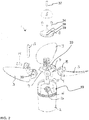
- FIG. 1-3 shows a propeller with foldable blades.
- Each cross dowels 12 is installed in a mating hole 15 at the hub 2, as illustrated in FIG. 2 .
- the cross dowels 12 further extend through holes 17 in lockbox flanges 18 of the lockboxes 7. This arrangement secures the triangular pivot pin structure and the blade roots 4 in the slots 19 in the hub 2 in a very solid manner.
- the anode 5 is installed at the hub end cap 6 using a screw 37 that engages a threaded hole 38 in the hub end cap 6.
- the hub end cap 6 is installed at the hub 2 using screws 34 that extend through corresponding apertures 39 in the hub end cap 6 and engage in threaded holes 33 in the ends of the cross dowels 12.
- a recess at each threaded hole 39 is arranged, where each recess (not shown) is configured for receiving the end of a cross dowel 12. This way, the cross dowels 12 are supported by the hub end cap 6 and the hub end cap 6 becomes a part of the structural arrangement and contributes in transferring the loads acting on the foldable propeller 1 when in use.
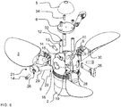
- the pivot pins 7 have their respective first ends and second ends arranged in a triangular shape, where the ends of two pivot pins are arranged adjacent each other.
- the respective ends are shaped with engagement members for engagement with a lockbox 7.
- the pivot pins 7 have a first end 20 and a second end 21 and a stem 29 therein between.
- the portion At the second end 21, there is provided a portion that is dimensioned larger than the first end 20, the portion forming a head 26 and comprises a pivot pin recess 24 for accommodating the first end 20 of a neighboring pivot pin 9 inside the head 26 when the pivot pins 9 are combined into a triangle, as illustrated in FIG. 4 .
- the head 26 and the stem 29 are formed as a single integral piece, for example moulded or machined as a single piece.
- a locking screw 14 extends through a corresponding hole 27 in the head 26 at the second end 21 and is fastened into the threaded hole 13 in a cross dowel 12.
- the head of the locking screw 14 is accommodated in recess 25 in the head 26 at the second end 21 of the pivot pin 9.
- each pivot pin 9 has an outer side 32 that when mounted is facing outwards from the rotational axis of the propeller 1.
- An opposite inner side 32 is facing the rotational axis of the propeller 1 when the pivot pin 9 is mounted.
- the inner side 31 at the first end 20 comprise a first concavity 11 which when mounted is abutting a first side of a cross dowel 12.
- Each head 26 comprises a second concavity 11' which when mounted is abutting a second side of the cross dowel 12.
- this enclosure of the cross dowel 12 between the concavities 11, 11' prevents lateral movements of the cross dowel 13.
- FIG. 6 is an exploded assembly drawing.
- the first ends 20 of the pivot pins 9 are each inserted into the hub 2 through apertures 16 in each of the three hub flanges 28.
- the pivot pins 9 are extending across the slots 19, with the stem 29 extending through the aperture 30 of the blade root gear 8 of the propeller blade 3 (not shown in FIG. 6 but similar as in FIG. 2 ) and into the holes 10 of an opposite hub flange 28 and then further extending into the head 26 at the second end 21 of a neighboring pivot pin 9, behind the holes 10, as also illustrated in FIG. 4a .
- the cross dowels 12 are inserted into the mating holes 15 of the hub, and the locking screws 14 are inserted through the holes 27 and screwed into the threaded holes 13 of the cross dowels 12.
- the recess 25 is accommodating the locking screw 14 head when the locking screw 14 is fastened.
- the gears 8 at the blade root 4 comprises two oppositely arranged pinion gears for intermeshing with the neighbouring blades' pinion gears in order to synchronize the pivot movement of the plurality of blades 4 from an active orientation, when the propeller rotates, to an inactive orientation where the blades are oriented folded backwards parallel or quasi parallel to the axis of rotation of the propeller 1.
- the first end 20 of the pivot pin 9 is slanted at an acute angle V relatively to the stem 29 in order for the outer side 31 of the stem 29 being longer than the inner side 31 of the stem 29.
- this first end 20 with the acute angel is used for giving passing-space for the stem 29 of another of the pivot pins 9 during insertion of the pivot pins 9 one after the other in the hub 2.
- the head 26 comprises an abutment cavity 24' that is abutting the outer side of the pivot pin 9 for holding the cavity 11 of the inner side 32 of the pivot pin 9 against the cross dowel 12.
- the end cap 6 in FIG. 6 is fastened with screws 34, similarly as illustrated in FIG. 2 , where the screws 34 are fastened into longitudinal threaded holes 33 at the top of the cross dowel 12.
- the anode 5 is fastened to the end cap 6 by a further screw.
- FIG. 7 illustrates different views of an alternative embodiment of a pivot pin 9 in which the first end 20 comprises a first part 35A, and the abutment cavity 24' in the recess 24 of the head 26 comprises a second part 35B of a notched interlock 35.
- such notched interlock 35 is illustrated in FIG. 8 for an embodiment of a square assembly of four pivot pins 9, although such interlock 35 is also workable for a triangular assembly of three pivot pins 9.
- the notches and recesses of the interlock 35 are formed as barb-shaped ribs, which eases assembly when the first end 20 of one pivot pin 9 is pushed into the head 26 of a second pivot pin 9 in a corner of a triangular of square assembly of pivot pins 9.
- FIG. 9 illustrates different views of an embodiment of a pivot pin 9, which is similar to the pivot pin 9 of FIG. 7 , however, without the first concavity 11 for the cross dowel 12, but with a threaded screw hole 36 in the first end 20. Also, the head 26 of the pivot pin 9 is free from a second concavity 11' for a cross dowel. Instead, for stability of the square assembly of pivot pins 9, or similarly for a triangular assembly, the first end 20 of the pivot pin 9 comprises a hole 36 with an inner threading 36' for cooperation with the corresponding outer threading of the locking screw 14.
- FIG. 10 An exemplary assembled form is illustrated in FIG. 10 for an embodiment of a square assembly of four pivot pins 9, although the interlock 35 is also workable for a triangular assembly of three pivot pins 9.
- Fig. 11 shows a two bladed foldable propeller in an exploded view with the pivot pins of FIG. 12 .
- the pivot pins 9 have a notched interlock 35, similarly to the embodiments of FIGs 7-10 .
- the bottom 24" of the pivot pin recess 24 is inclined relatively to the longitudinal axis 40 of the pivot pin 9.
- the first end 20 of the pivot pin 9 is slanted at an acute angle relatively to the stem 29 such that the outer side 31 of the stem 29 is longer than the inner side 32 of the stem 29 and, thus, fitting tightly into the pin recess 24 where the first end 20 of the pivot pin 9 is abutting the bottom 24" of the pivot pin recess 24.
- the slanted first end 20 of the pivot pin 9 acts as a wedge relatively to the second part 35B of the interlock 35 when the pivot pin 9 is inserted into the pivot pin recess 24 such that the first part 35A of the interlock 35 is is secured in engagement with the second part 35B of the interlock 35.
Landscapes
- Chemical & Material Sciences (AREA)
- Engineering & Computer Science (AREA)
- Combustion & Propulsion (AREA)
- Mechanical Engineering (AREA)
- Ocean & Marine Engineering (AREA)
- Harvester Elements (AREA)
- Structures Of Non-Positive Displacement Pumps (AREA)
- Shafts, Cranks, Connecting Bars, And Related Bearings (AREA)
Priority Applications (2)
| Application Number | Priority Date | Filing Date | Title |
|---|---|---|---|
| SI201830032T SI3418180T1 (sl) | 2017-06-19 | 2018-06-13 | Zložljiv propeler in postopek za sestavljanje |
| PL18177454T PL3418180T3 (pl) | 2017-06-19 | 2018-06-13 | Składana śruba napędowa i sposób montażu |
Applications Claiming Priority (1)
| Application Number | Priority Date | Filing Date | Title |
|---|---|---|---|
| DKPA201770477A DK179393B1 (en) | 2017-06-19 | 2017-06-19 | Foldable propeller and method for assembly |
Publications (2)
| Publication Number | Publication Date |
|---|---|
| EP3418180A1 EP3418180A1 (en) | 2018-12-26 |
| EP3418180B1 true EP3418180B1 (en) | 2019-11-20 |
Family
ID=62189445
Family Applications (1)
| Application Number | Title | Priority Date | Filing Date |
|---|---|---|---|
| EP18177454.8A Active EP3418180B1 (en) | 2017-06-19 | 2018-06-13 | Foldable propeller and method for assembly |
Country Status (5)
| Country | Link |
|---|---|
| US (1) | US10793243B2 (pl) |
| EP (1) | EP3418180B1 (pl) |
| DK (1) | DK179393B1 (pl) |
| PL (1) | PL3418180T3 (pl) |
| SI (1) | SI3418180T1 (pl) |
Families Citing this family (2)
| Publication number | Priority date | Publication date | Assignee | Title |
|---|---|---|---|---|
| DK179125B1 (en) * | 2016-02-18 | 2017-11-20 | Flexofold Aps | Folding propeller |
| KR102592023B1 (ko) * | 2021-11-03 | 2023-10-19 | 한국항공우주연구원 | 항공기용 프로펠러 허브 |
Family Cites Families (7)
| Publication number | Priority date | Publication date | Assignee | Title |
|---|---|---|---|---|
| US5183384A (en) * | 1988-05-16 | 1993-02-02 | Trumbly Joe H | Foldable propeller assembly |
| DK553389A (da) * | 1989-11-07 | 1991-05-08 | Bo Bojsen | Foldepropel |
| US5403217A (en) * | 1994-04-18 | 1995-04-04 | Vosper; George W. | Folding blade propeller |
| AUPN617295A0 (en) * | 1995-10-25 | 1995-11-16 | Tristream Propeller Company Pty Limited | An improved propeller |
| SE509770C2 (sv) * | 1995-11-28 | 1999-03-08 | Volvo Penta Ab | Propeller |
| DK178074B1 (en) * | 2013-10-14 | 2015-05-04 | Flexofold Aps | Folding propeller |
| GB201415491D0 (en) * | 2014-09-02 | 2014-10-15 | Superprop Ltd | Propeller |
-
2017
- 2017-06-19 DK DKPA201770477A patent/DK179393B1/en active
-
2018
- 2018-06-13 PL PL18177454T patent/PL3418180T3/pl unknown
- 2018-06-13 EP EP18177454.8A patent/EP3418180B1/en active Active
- 2018-06-13 SI SI201830032T patent/SI3418180T1/sl unknown
- 2018-06-19 US US16/011,795 patent/US10793243B2/en active Active
Non-Patent Citations (1)
| Title |
|---|
| None * |
Also Published As
| Publication number | Publication date |
|---|---|
| PL3418180T3 (pl) | 2020-09-07 |
| DK201770477A1 (en) | 2018-05-28 |
| EP3418180A1 (en) | 2018-12-26 |
| SI3418180T1 (sl) | 2020-04-30 |
| DK179393B1 (en) | 2018-05-28 |
| US10793243B2 (en) | 2020-10-06 |
| US20190135395A1 (en) | 2019-05-09 |
Similar Documents
| Publication | Publication Date | Title |
|---|---|---|
| EP3057864B1 (en) | Folding propeller | |
| EP3418180B1 (en) | Foldable propeller and method for assembly | |
| CN215622624U (zh) | 螺旋桨及船用推进器 | |
| US7806661B2 (en) | Propeller | |
| US20200156748A1 (en) | Propeller | |
| CN101830277A (zh) | 船舶螺旋桨 | |
| US7025642B1 (en) | Boat propeller | |
| EP2484583A1 (en) | Boat propulsion device | |
| EP3416884B1 (en) | Folding propeller | |
| KR20150043467A (ko) | 전방 스크류를 갖는 링 프로펠러 | |
| US20140072445A1 (en) | Demountable Propeller | |
| US20140133992A1 (en) | Connection mechanism for mounting blades for a wind turbine | |
| CN114364606B (zh) | 海洋船舶螺旋桨和用于安装海洋船舶螺旋桨的方法 | |
| JP6605272B2 (ja) | 船舶用可変ピッチプロペラ | |
| JP2000249037A (ja) | 風車の翼取り付け構造 | |
| CN210083513U (zh) | 船舶及其螺旋桨的紧固组件 | |
| EP3168457A1 (en) | Wind turbine with blades with a coning angle | |
| US12065226B1 (en) | Fixed-pitch bolted propeller | |
| EP2532579B1 (en) | Propeller having dismountable blades | |
| WO2017178061A1 (en) | A propeller for a marine vessel and a method of installing the hub cap to the hub | |
| RU2781501C1 (ru) | Гребной винт морского судна, лопасть гребного винта и способ установки гребного винта морского судна | |
| GB2345732A (en) | Thrust balanced propeller | |
| EP2698314A1 (en) | Demountable propeller |
Legal Events
| Date | Code | Title | Description |
|---|---|---|---|
| PUAI | Public reference made under article 153(3) epc to a published international application that has entered the european phase |
Free format text: ORIGINAL CODE: 0009012 |
|
| STAA | Information on the status of an ep patent application or granted ep patent |
Free format text: STATUS: THE APPLICATION HAS BEEN PUBLISHED |
|
| AK | Designated contracting states |
Kind code of ref document: A1 Designated state(s): AL AT BE BG CH CY CZ DE DK EE ES FI FR GB GR HR HU IE IS IT LI LT LU LV MC MK MT NL NO PL PT RO RS SE SI SK SM TR |
|
| AX | Request for extension of the european patent |
Extension state: BA ME |
|
| STAA | Information on the status of an ep patent application or granted ep patent |
Free format text: STATUS: REQUEST FOR EXAMINATION WAS MADE |
|
| GRAP | Despatch of communication of intention to grant a patent |
Free format text: ORIGINAL CODE: EPIDOSNIGR1 |
|
| STAA | Information on the status of an ep patent application or granted ep patent |
Free format text: STATUS: GRANT OF PATENT IS INTENDED |
|
| 17P | Request for examination filed |
Effective date: 20190612 |
|
| RBV | Designated contracting states (corrected) |
Designated state(s): AL AT BE BG CH CY CZ DE DK EE ES FI FR GB GR HR HU IE IS IT LI LT LU LV MC MK MT NL NO PL PT RO RS SE SI SK SM TR |
|
| RIC1 | Information provided on ipc code assigned before grant |
Ipc: B63H 1/22 20060101AFI20190627BHEP |
|
| INTG | Intention to grant announced |
Effective date: 20190718 |
|
| GRAA | (expected) grant |
Free format text: ORIGINAL CODE: 0009210 |
|
| STAA | Information on the status of an ep patent application or granted ep patent |
Free format text: STATUS: THE PATENT HAS BEEN GRANTED |
|
| GRAS | Grant fee paid |
Free format text: ORIGINAL CODE: EPIDOSNIGR3 |
|
| AK | Designated contracting states |
Kind code of ref document: B1 Designated state(s): AL AT BE BG CH CY CZ DE DK EE ES FI FR GB GR HR HU IE IS IT LI LT LU LV MC MK MT NL NO PL PT RO RS SE SI SK SM TR |
|
| REG | Reference to a national code |
Ref country code: GB Ref legal event code: FG4D |
|
| REG | Reference to a national code |
Ref country code: CH Ref legal event code: EP |
|
| REG | Reference to a national code |
Ref country code: DE Ref legal event code: R096 Ref document number: 602018001256 Country of ref document: DE |
|
| REG | Reference to a national code |
Ref country code: IE Ref legal event code: FG4D |
|
| REG | Reference to a national code |
Ref country code: AT Ref legal event code: REF Ref document number: 1203894 Country of ref document: AT Kind code of ref document: T Effective date: 20191215 |
|
| REG | Reference to a national code |
Ref country code: NL Ref legal event code: MP Effective date: 20191120 |
|
| REG | Reference to a national code |
Ref country code: LT Ref legal event code: MG4D |
|
| PG25 | Lapsed in a contracting state [announced via postgrant information from national office to epo] |
Ref country code: NL Free format text: LAPSE BECAUSE OF FAILURE TO SUBMIT A TRANSLATION OF THE DESCRIPTION OR TO PAY THE FEE WITHIN THE PRESCRIBED TIME-LIMIT Effective date: 20191120 Ref country code: LT Free format text: LAPSE BECAUSE OF FAILURE TO SUBMIT A TRANSLATION OF THE DESCRIPTION OR TO PAY THE FEE WITHIN THE PRESCRIBED TIME-LIMIT Effective date: 20191120 Ref country code: SE Free format text: LAPSE BECAUSE OF FAILURE TO SUBMIT A TRANSLATION OF THE DESCRIPTION OR TO PAY THE FEE WITHIN THE PRESCRIBED TIME-LIMIT Effective date: 20191120 Ref country code: LV Free format text: LAPSE BECAUSE OF FAILURE TO SUBMIT A TRANSLATION OF THE DESCRIPTION OR TO PAY THE FEE WITHIN THE PRESCRIBED TIME-LIMIT Effective date: 20191120 Ref country code: GR Free format text: LAPSE BECAUSE OF FAILURE TO SUBMIT A TRANSLATION OF THE DESCRIPTION OR TO PAY THE FEE WITHIN THE PRESCRIBED TIME-LIMIT Effective date: 20200221 Ref country code: NO Free format text: LAPSE BECAUSE OF FAILURE TO SUBMIT A TRANSLATION OF THE DESCRIPTION OR TO PAY THE FEE WITHIN THE PRESCRIBED TIME-LIMIT Effective date: 20200220 Ref country code: FI Free format text: LAPSE BECAUSE OF FAILURE TO SUBMIT A TRANSLATION OF THE DESCRIPTION OR TO PAY THE FEE WITHIN THE PRESCRIBED TIME-LIMIT Effective date: 20191120 Ref country code: BG Free format text: LAPSE BECAUSE OF FAILURE TO SUBMIT A TRANSLATION OF THE DESCRIPTION OR TO PAY THE FEE WITHIN THE PRESCRIBED TIME-LIMIT Effective date: 20200220 |
|
| PG25 | Lapsed in a contracting state [announced via postgrant information from national office to epo] |
Ref country code: IS Free format text: LAPSE BECAUSE OF FAILURE TO SUBMIT A TRANSLATION OF THE DESCRIPTION OR TO PAY THE FEE WITHIN THE PRESCRIBED TIME-LIMIT Effective date: 20200320 Ref country code: HR Free format text: LAPSE BECAUSE OF FAILURE TO SUBMIT A TRANSLATION OF THE DESCRIPTION OR TO PAY THE FEE WITHIN THE PRESCRIBED TIME-LIMIT Effective date: 20191120 Ref country code: RS Free format text: LAPSE BECAUSE OF FAILURE TO SUBMIT A TRANSLATION OF THE DESCRIPTION OR TO PAY THE FEE WITHIN THE PRESCRIBED TIME-LIMIT Effective date: 20191120 |
|
| PG25 | Lapsed in a contracting state [announced via postgrant information from national office to epo] |
Ref country code: AL Free format text: LAPSE BECAUSE OF FAILURE TO SUBMIT A TRANSLATION OF THE DESCRIPTION OR TO PAY THE FEE WITHIN THE PRESCRIBED TIME-LIMIT Effective date: 20191120 |
|
| PG25 | Lapsed in a contracting state [announced via postgrant information from national office to epo] |
Ref country code: PT Free format text: LAPSE BECAUSE OF FAILURE TO SUBMIT A TRANSLATION OF THE DESCRIPTION OR TO PAY THE FEE WITHIN THE PRESCRIBED TIME-LIMIT Effective date: 20200412 Ref country code: EE Free format text: LAPSE BECAUSE OF FAILURE TO SUBMIT A TRANSLATION OF THE DESCRIPTION OR TO PAY THE FEE WITHIN THE PRESCRIBED TIME-LIMIT Effective date: 20191120 Ref country code: DK Free format text: LAPSE BECAUSE OF FAILURE TO SUBMIT A TRANSLATION OF THE DESCRIPTION OR TO PAY THE FEE WITHIN THE PRESCRIBED TIME-LIMIT Effective date: 20191120 Ref country code: CZ Free format text: LAPSE BECAUSE OF FAILURE TO SUBMIT A TRANSLATION OF THE DESCRIPTION OR TO PAY THE FEE WITHIN THE PRESCRIBED TIME-LIMIT Effective date: 20191120 Ref country code: ES Free format text: LAPSE BECAUSE OF FAILURE TO SUBMIT A TRANSLATION OF THE DESCRIPTION OR TO PAY THE FEE WITHIN THE PRESCRIBED TIME-LIMIT Effective date: 20191120 Ref country code: RO Free format text: LAPSE BECAUSE OF FAILURE TO SUBMIT A TRANSLATION OF THE DESCRIPTION OR TO PAY THE FEE WITHIN THE PRESCRIBED TIME-LIMIT Effective date: 20191120 |
|
| REG | Reference to a national code |
Ref country code: AT Ref legal event code: MK05 Ref document number: 1203894 Country of ref document: AT Kind code of ref document: T Effective date: 20191120 |
|
| REG | Reference to a national code |
Ref country code: DE Ref legal event code: R097 Ref document number: 602018001256 Country of ref document: DE |
|
| PG25 | Lapsed in a contracting state [announced via postgrant information from national office to epo] |
Ref country code: SM Free format text: LAPSE BECAUSE OF FAILURE TO SUBMIT A TRANSLATION OF THE DESCRIPTION OR TO PAY THE FEE WITHIN THE PRESCRIBED TIME-LIMIT Effective date: 20191120 Ref country code: SK Free format text: LAPSE BECAUSE OF FAILURE TO SUBMIT A TRANSLATION OF THE DESCRIPTION OR TO PAY THE FEE WITHIN THE PRESCRIBED TIME-LIMIT Effective date: 20191120 |
|
| PLBE | No opposition filed within time limit |
Free format text: ORIGINAL CODE: 0009261 |
|
| STAA | Information on the status of an ep patent application or granted ep patent |
Free format text: STATUS: NO OPPOSITION FILED WITHIN TIME LIMIT |
|
| 26N | No opposition filed |
Effective date: 20200821 |
|
| PG25 | Lapsed in a contracting state [announced via postgrant information from national office to epo] |
Ref country code: AT Free format text: LAPSE BECAUSE OF FAILURE TO SUBMIT A TRANSLATION OF THE DESCRIPTION OR TO PAY THE FEE WITHIN THE PRESCRIBED TIME-LIMIT Effective date: 20191120 |
|
| PG25 | Lapsed in a contracting state [announced via postgrant information from national office to epo] |
Ref country code: MC Free format text: LAPSE BECAUSE OF FAILURE TO SUBMIT A TRANSLATION OF THE DESCRIPTION OR TO PAY THE FEE WITHIN THE PRESCRIBED TIME-LIMIT Effective date: 20191120 |
|
| PG25 | Lapsed in a contracting state [announced via postgrant information from national office to epo] |
Ref country code: LU Free format text: LAPSE BECAUSE OF NON-PAYMENT OF DUE FEES Effective date: 20200613 |
|
| REG | Reference to a national code |
Ref country code: BE Ref legal event code: MM Effective date: 20200630 |
|
| PG25 | Lapsed in a contracting state [announced via postgrant information from national office to epo] |
Ref country code: IE Free format text: LAPSE BECAUSE OF NON-PAYMENT OF DUE FEES Effective date: 20200613 |
|
| PG25 | Lapsed in a contracting state [announced via postgrant information from national office to epo] |
Ref country code: BE Free format text: LAPSE BECAUSE OF NON-PAYMENT OF DUE FEES Effective date: 20200630 |
|
| REG | Reference to a national code |
Ref country code: CH Ref legal event code: PL |
|
| PG25 | Lapsed in a contracting state [announced via postgrant information from national office to epo] |
Ref country code: LI Free format text: LAPSE BECAUSE OF NON-PAYMENT OF DUE FEES Effective date: 20210630 Ref country code: CH Free format text: LAPSE BECAUSE OF NON-PAYMENT OF DUE FEES Effective date: 20210630 |
|
| PG25 | Lapsed in a contracting state [announced via postgrant information from national office to epo] |
Ref country code: TR Free format text: LAPSE BECAUSE OF FAILURE TO SUBMIT A TRANSLATION OF THE DESCRIPTION OR TO PAY THE FEE WITHIN THE PRESCRIBED TIME-LIMIT Effective date: 20191120 Ref country code: MT Free format text: LAPSE BECAUSE OF FAILURE TO SUBMIT A TRANSLATION OF THE DESCRIPTION OR TO PAY THE FEE WITHIN THE PRESCRIBED TIME-LIMIT Effective date: 20191120 Ref country code: CY Free format text: LAPSE BECAUSE OF FAILURE TO SUBMIT A TRANSLATION OF THE DESCRIPTION OR TO PAY THE FEE WITHIN THE PRESCRIBED TIME-LIMIT Effective date: 20191120 |
|
| PG25 | Lapsed in a contracting state [announced via postgrant information from national office to epo] |
Ref country code: MK Free format text: LAPSE BECAUSE OF FAILURE TO SUBMIT A TRANSLATION OF THE DESCRIPTION OR TO PAY THE FEE WITHIN THE PRESCRIBED TIME-LIMIT Effective date: 20191120 |
|
| P01 | Opt-out of the competence of the unified patent court (upc) registered |
Effective date: 20230514 |
|
| PGFP | Annual fee paid to national office [announced via postgrant information from national office to epo] |
Ref country code: PL Payment date: 20250521 Year of fee payment: 8 Ref country code: DE Payment date: 20250627 Year of fee payment: 8 |
|
| PGFP | Annual fee paid to national office [announced via postgrant information from national office to epo] |
Ref country code: GB Payment date: 20250627 Year of fee payment: 8 |
|
| PGFP | Annual fee paid to national office [announced via postgrant information from national office to epo] |
Ref country code: FR Payment date: 20250625 Year of fee payment: 8 |
|
| PGFP | Annual fee paid to national office [announced via postgrant information from national office to epo] |
Ref country code: SI Payment date: 20250519 Year of fee payment: 8 |
|
| PGFP | Annual fee paid to national office [announced via postgrant information from national office to epo] |
Ref country code: IT Payment date: 20250619 Year of fee payment: 8 |