EP3418111A1 - Siège pour véhicule - Google Patents
Siège pour véhicule Download PDFInfo
- Publication number
- EP3418111A1 EP3418111A1 EP18178785.4A EP18178785A EP3418111A1 EP 3418111 A1 EP3418111 A1 EP 3418111A1 EP 18178785 A EP18178785 A EP 18178785A EP 3418111 A1 EP3418111 A1 EP 3418111A1
- Authority
- EP
- European Patent Office
- Prior art keywords
- seat
- point
- tension
- backrest
- attachment
- Prior art date
- Legal status (The legal status is an assumption and is not a legal conclusion. Google has not performed a legal analysis and makes no representation as to the accuracy of the status listed.)
- Granted
Links
Images


Classifications
-
- B—PERFORMING OPERATIONS; TRANSPORTING
- B60—VEHICLES IN GENERAL
- B60N—SEATS SPECIALLY ADAPTED FOR VEHICLES; VEHICLE PASSENGER ACCOMMODATION NOT OTHERWISE PROVIDED FOR
- B60N2/00—Seats specially adapted for vehicles; Arrangement or mounting of seats in vehicles
- B60N2/24—Seats specially adapted for vehicles; Arrangement or mounting of seats in vehicles for particular purposes or particular vehicles
- B60N2/42—Seats specially adapted for vehicles; Arrangement or mounting of seats in vehicles for particular purposes or particular vehicles the seat constructed to protect the occupant from the effect of abnormal g-forces, e.g. crash or safety seats
- B60N2/427—Seats or parts thereof displaced during a crash
- B60N2/42709—Seats or parts thereof displaced during a crash involving residual deformation or fracture of the structure
-
- B—PERFORMING OPERATIONS; TRANSPORTING
- B60—VEHICLES IN GENERAL
- B60N—SEATS SPECIALLY ADAPTED FOR VEHICLES; VEHICLE PASSENGER ACCOMMODATION NOT OTHERWISE PROVIDED FOR
- B60N2/00—Seats specially adapted for vehicles; Arrangement or mounting of seats in vehicles
- B60N2/24—Seats specially adapted for vehicles; Arrangement or mounting of seats in vehicles for particular purposes or particular vehicles
-
- B—PERFORMING OPERATIONS; TRANSPORTING
- B60—VEHICLES IN GENERAL
- B60N—SEATS SPECIALLY ADAPTED FOR VEHICLES; VEHICLE PASSENGER ACCOMMODATION NOT OTHERWISE PROVIDED FOR
- B60N2/00—Seats specially adapted for vehicles; Arrangement or mounting of seats in vehicles
- B60N2/24—Seats specially adapted for vehicles; Arrangement or mounting of seats in vehicles for particular purposes or particular vehicles
- B60N2/30—Non-dismountable or dismountable seats storable in a non-use position, e.g. foldable spare seats
- B60N2/3038—Cushion movements
- B60N2/304—Cushion movements by rotation only
- B60N2/3045—Cushion movements by rotation only about transversal axis
- B60N2/305—Cushion movements by rotation only about transversal axis the cushion being hinged on the vehicle frame
-
- B—PERFORMING OPERATIONS; TRANSPORTING
- B60—VEHICLES IN GENERAL
- B60N—SEATS SPECIALLY ADAPTED FOR VEHICLES; VEHICLE PASSENGER ACCOMMODATION NOT OTHERWISE PROVIDED FOR
- B60N2/00—Seats specially adapted for vehicles; Arrangement or mounting of seats in vehicles
- B60N2/24—Seats specially adapted for vehicles; Arrangement or mounting of seats in vehicles for particular purposes or particular vehicles
- B60N2/42—Seats specially adapted for vehicles; Arrangement or mounting of seats in vehicles for particular purposes or particular vehicles the seat constructed to protect the occupant from the effect of abnormal g-forces, e.g. crash or safety seats
- B60N2/4207—Seats specially adapted for vehicles; Arrangement or mounting of seats in vehicles for particular purposes or particular vehicles the seat constructed to protect the occupant from the effect of abnormal g-forces, e.g. crash or safety seats characterised by the direction of the g-forces
- B60N2/4242—Seats specially adapted for vehicles; Arrangement or mounting of seats in vehicles for particular purposes or particular vehicles the seat constructed to protect the occupant from the effect of abnormal g-forces, e.g. crash or safety seats characterised by the direction of the g-forces vertical
-
- B—PERFORMING OPERATIONS; TRANSPORTING
- B60—VEHICLES IN GENERAL
- B60N—SEATS SPECIALLY ADAPTED FOR VEHICLES; VEHICLE PASSENGER ACCOMMODATION NOT OTHERWISE PROVIDED FOR
- B60N2/00—Seats specially adapted for vehicles; Arrangement or mounting of seats in vehicles
- B60N2/70—Upholstery springs ; Upholstery
- B60N2/7011—Upholstery springs ; Upholstery of substantially two-dimensional shape, e.g. hammock-like, plastic shells, fabrics
Definitions
- the technical field of the invention is that of the seats with pivoting seat and soft backrest for the boarding of military personnel.
- Such a file can not be coupled with a seat according to the patent FR2932428 because in case of rupture of the abutment the stretched backrest opposes the free collapse of the seat in a way harmful to the occupant.
- the invention proposes to solve the problem of obstruction of subsidence caused by a flexible file.
- the invention provides a file tensioning means favorable to the accessibility of the parts located behind the seat.
- the invention relates to a vehicle seat comprising a seat pivotable about an axis between at least three angular positions, a substantially vertical folded position, a use position where the seat interferes with a seat stop and a collapsed position. located lower than the use position and obtained by breaking the abutment following a shock, seat characterized in that it has a flexible backrest intended to be made integral with an upper attachment point by its first end and secured to the seat by its second end at a fixing point, the folder passing through a tension point positioned in a manner such that, when the seat is in the position of use, the point of tension is aligned with the point of attachment and the axis, the axis being situated between the point of tension and the point of attachment, the tension of the The backrest is thus maximum and does not prevent sagging of the seat.
- the fastening of the backrest with the upper point of attachment is done by means of at least one hook.
- the point of tension is located in the vicinity of the axis.
- the point of tension is part of a baffle in which the file winds.
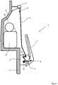
- a seat 1 comprises a seat 2 and a backrest 3.
- the seat 2 is pivotable relative to the backrest 3 about an axis 4 integral with a frame 5 of the seat 1, frame 5 integral with a wall 9 of a vehicle.
- the backrest 3 is flexible and comprises at its first end or upper end a fastening means 6 making it integral with a fastening point 7 fixed to the wall 9.
- a fastening means 6 may comprise for example a hook 6 adapted to correspond with a ring 7 for fixing the seat 1.
- the second end of the backrest is secured to the seat 2 at a fixing point 8.
- the seat 2 is substantially vertical.
- the backrest 3 is relaxed which allows a passenger (unrepresented passenger) can pick up the hook 6 of the first end of the folder 3 to access anything that may be behind it.
- the passenger can access luggage 10 located in a housing 9a formed by a concavity of the wall 9 of the vehicle.
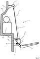
- the seat 2 is lowered in a substantially horizontal position allowing a passenger (passenger not shown) to sit.
- This position is obtained by pivoting the seat 2 about the axis 4 and relative to the backrest 3 and the frame 5.
- the pivoting of the seat 2 is stopped by interference of the seat 2 with a stop 12.
- the lowering of the seat 2 has the effect of moving each of the ends of the backrest 3 resulting in the tension of the backrest 3; which provides a comfort to the passenger who is thus kept away from the elements that can be behind the backrest 3.
- the backrest 3 passes through a baffle 13 having a first and a second bar 13a and 13b between which it winds.
- This baffle 13 serves to deflect the backrest 3 of the straight line L connecting each end of the backrest 3 to give the backrest 3 an appropriate tilt to the comfort of the passenger.
- the first bar 13a of this baffle 13 also forms a point of tension for the backrest 3. In this position of use, the backrest 3 is at its maximum tension compared to its tension in the other positions adoptable by the seat 2 and according to the conditions that we will develop further.
- the seat 2 is then free to pivot downwards, that is to say to sag, under the effect of the weight of the passenger (passenger not shown) without this passenger experiencing transmission of traumatic solicitations.
- the backrest 3 relaxes as and when pivoting down the seat 2.
- the backrest 3 does not prevent the sagging of the seat 2 since the tension of it decreases beyond the use position.
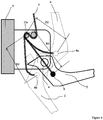
- the skilled person will arrange the seat 1 so that in the position of use, the point of tension constituted by the first bar 13a is in the alignment formed by the axis 4 and the fixing point 8.
- the axis 4 being furthermore situated between the point of tension 13a and the point of attachment 8.
- the distance D1 ( figure 4 ) between the point of attachment 8 and the point of tension 13a is greater than the distance D2 and D3 separating these two points in the respective folded and collapsed positions 8a and 8b, positions which are shown in fine lines (folded position) and in dotted lines (position collapsed) on the figure 4 .
- the figure 5 shows another simplified embodiment in which the tension point 13 is located in the vicinity of the axis 4 and is formed by a single bar 13 without baffle.
Landscapes
- Engineering & Computer Science (AREA)
- Aviation & Aerospace Engineering (AREA)
- Transportation (AREA)
- Mechanical Engineering (AREA)
- Seats For Vehicles (AREA)
Abstract
Description
- Le domaine technique de l'invention est celui des sièges à assise pivotante et dossier souple pour l'embarquement de personnels militaires.
- Il est connu du brevet
FR2932428 - Pour le confort de l'occupant d'un tel siège, il est possible de l'équiper d'un dossier souple tel qu'un dossier textile. Un tel type de dossier est décrit par le brevet
EP2132057 . Il relie une partie haute du siège à un point de fixation situé au niveau de l'assise. L'abaissement de l'assise en position d'usage provoque la tension du dossier fournissant ainsi un supplément de confort. - Un tel dossier ne peut pas être couplé avec un siège selon le brevet
FR2932428 - L'invention propose de résoudre le problème d'entrave à l'affaissement causé par un dossier souple.
- En outre, l'invention propose un moyen de tension du dossier favorable à l'accessibilité des parties situées en arrière du siège.
- L'invention porte sur un siège pour véhicule comportant une assise pivotable autour d'un axe entre au moins trois positions angulaires, une position repliée sensiblement verticale, une position d'usage où l'assise interfère avec une butée du siège et une position affaissée située plus bas que la position d'usage et obtenue par rupture de la butée consécutivement à un choc, siège caractérisé en ce qu'il comporte un dossier souple destiné à être rendu solidaire avec un point d'accrochage supérieur par sa première extrémité et solidaire de l'assise par sa seconde extrémité au niveau d'un point de fixation, le dossier passant par un point de tension positionné de manière telle que, lorsque l'assise est en position d'usage, le point de tension se trouve aligné avec le point de fixation et l'axe, l'axe étant situé entre le point de tension et le point de fixation, la tension du dossier se trouve ainsi maximale et ne s'oppose pas à l'affaissement de l'assise.
- Avantageusement, la solidarisation du dossier avec le point d'accrochage supérieur se fait au moyen d'au moins un crochet.
- Avantageusement, le point de tension est situé au voisinage de l'axe.
- Avantageusement, le point de tension fait partie d'une chicane dans laquelle serpente le dossier.
- L'invention sera mieux comprise à la lecture de la description suivante, description faite à la lumière des dessins figurant en annexe, dessins dans lesquels :
- La
figure 1 représente une vue latérale d'un siège selon l'invention en position repliée. - La
figure 2 représente une vue latérale d'un siège selon l'invention en position d'usage. - La
figure 3 représente une vue latérale d'un siège selon l'invention en position affaissée. - La
figure 4 représente une vue latérale de détail d'un siège selon l'invention avec l'assise dans différentes positions. - La
figure 5 représente une vue latérale d'un siège selon un second mode de réalisation de l'invention en position d'usage. - Selon la
figure 1 , un siège 1 comporte une assise 2 et un dossier 3. L'assise 2 est pivotante relativement au dossier 3 autour d'un axe 4 solidaire d'un bâti 5 du siège 1, bâti 5 solidaire d'une paroi 9 d'un véhicule. - Le dossier 3 est souple et comporte au niveau de sa première extrémité ou extrémité supérieure un moyen d'accrochage 6 le rendant solidarisable d'un point d'accrochage 7 fixé à la paroi 9. Un tel moyen 6 pourra comporter par exemple un crochet 6 apte à correspondre avec un anneau 7 de fixation du siège 1.
- La seconde extrémité du dossier est solidaire de l'assise 2 au niveau d'un point de fixation 8. Dans la configuration représentée correspondant à la position repliée, l'assise 2 est sensiblement verticale. Le dossier 3 est détendu ce qui permet à un passager (passager non représenté) de pouvoir décrocher le crochet 6 de la première extrémité du dossier 3 afin d'accéder à toute chose pouvant se trouver derrière celui-ci. Par exemple, le passager pourra accéder à des bagages 10 situés dans un logement 9a formé par une concavité de la paroi 9 du véhicule.
- Selon la
figure 2 , l'assise 2 est abaissée dans une position sensiblement horizontale permettant à un passager (passager non représenté) de s'assoir. Cette position, dite position d'usage, est obtenue par pivotement de l'assise 2 autour de l'axe 4 et relativement au dossier 3 et au bâti 5. - Le pivotement de l'assise 2 est arrêté par interférence de l'assise 2 avec une butée 12. L'abaissement de l'assise 2 a pour effet d'éloigner chacune des extrémités du dossier 3 aboutissant à la tension du dossier 3, ce qui apporte un confort dorsal au passager qui est ainsi tenu à distance des éléments pouvant se trouver derrière le dossier 3.
- Le dossier 3 passe par une chicane 13 comportant un premier et un second barreau 13a et 13b entre lesquels il serpente. Cette chicane 13 a pour fonction de dévier le dossier 3 de la ligne droite L reliant chacune des extrémités du dossier 3 afin de donner au dossier 3 une inclinaison appropriée au confort du passager. Le premier barreau 13a de cette chicane 13 forme aussi un point de tension pour le dossier 3. Dans cette position d'usage, le dossier 3 est à sa tension maximale comparativement à sa tension dans les autres positions adoptables par l'assise 2 et selon les conditions que nous allons développer plus loin.
- Selon la
figure 3 , consécutivement à un choc vertical violent du type choc de mine, l'appui de l'assise 2 sur la butée 12 a provoqué la rupture de celle-ci qui est dimensionnée pour rompre au-delà d'un niveau de sollicitation déterminé comme décrit dans le brevetFR2932428 - L'assise 2 est alors libre de pivoter vers le bas, c'est-à-dire de s'affaisser, sous l'effet du poids du passager (passager non représenté) sans que ce passager ne subisse de transmission de sollicitations traumatisantes. En s'affaissant de la sorte, le dossier 3 se détend au fur et à mesure du pivotement vers le bas de l'assise 2. Le dossier 3 ne s'oppose pas à l'affaissement de l'assise 2 puisque la tension de celui-ci diminue au-delà de la position d'usage.
- Pour obtenir cet effet technique, l'Homme du Métier agencera le siège 1 de manière à ce qu'en position d'usage, le point de tension constitué par le premier barreau 13a se situe dans l'alignement formé par l'axe 4 et le point de fixation 8. L'axe 4 étant par ailleurs situé entre le point de tension 13a et le point de fixation 8.
- De cette façon, la distance D1 (
figure 4 ) entre le point de fixation 8 et le point de tension 13a est supérieure aux distance D2 et D3 séparant ces deux points dans les positions respectives repliée 8a et affaissée 8b, positions qui sont représentées en trait fin (position repliée) et en pointillés (position affaissée) sur lafigure 4 . - La
figure 5 montre un autre mode de réalisation simplifié dans lequel le point de tension 13 est situé au voisinage de l'axe 4 et il est formé par un barreau unique 13 sans chicane.
Claims (4)
- Siège (1) pour véhicule comportant une assise (2) pivotable autour d'un axe (4) entre au moins trois positions angulaires, une position repliée sensiblement verticale, une position d'usage où l'assise (2) interfère avec une butée (12) du siège et une position affaissée située plus bas que la position d'usage et obtenue par rupture de la butée (12) consécutivement à un choc, siège (1) caractérisé en ce qu'il comporte un dossier (3) souple destiné à être rendu solidaire avec un point d'accrochage (7) supérieur par sa première extrémité et solidaire de l'assise (2) par sa seconde extrémité au niveau d'un point de fixation (8), le dossier (3) passant par un point de tension (13) positionné de manière telle que, lorsque l'assise (2) est en position d'usage, le point de tension (13,13a) se trouve aligné avec le point de fixation (8) et l'axe (4), l'axe (4) étant situé entre le point de tension (13,13a) et le point de fixation (8), la tension du dossier (3) se trouve ainsi maximale et ne s'oppose pas à l'affaissement de l'assise (2).
- Siège (1) selon la revendication 1, caractérisé en ce que la solidarisation du dossier (3) avec le point d'accrochage supérieur (7) se fait au moyen d'au moins un crochet (6).
- Siège (1) selon une des revendications 1 ou 2, caractérisé en ce que le point de tension (13) est situé au voisinage de l'axe (4).
- Siège (1) selon une des revendications 1 à 3, caractérisé en ce que le point de tension (13a) fait partie d'une chicane (13a,13b) dans laquelle serpente le dossier (3) .
Applications Claiming Priority (1)
| Application Number | Priority Date | Filing Date | Title |
|---|---|---|---|
| FR1700672A FR3067990B1 (fr) | 2017-06-22 | 2017-06-22 | Tendeur de dossier de siege pour vehicule |
Publications (2)
| Publication Number | Publication Date |
|---|---|
| EP3418111A1 true EP3418111A1 (fr) | 2018-12-26 |
| EP3418111B1 EP3418111B1 (fr) | 2020-04-01 |
Family
ID=60450689
Family Applications (1)
| Application Number | Title | Priority Date | Filing Date |
|---|---|---|---|
| EP18178785.4A Active EP3418111B1 (fr) | 2017-06-22 | 2018-06-20 | Siège pour véhicule |
Country Status (3)
| Country | Link |
|---|---|
| EP (1) | EP3418111B1 (fr) |
| ES (1) | ES2788053T3 (fr) |
| FR (1) | FR3067990B1 (fr) |
Families Citing this family (1)
| Publication number | Priority date | Publication date | Assignee | Title |
|---|---|---|---|---|
| FR3097485B1 (fr) | 2019-06-24 | 2021-06-04 | Nexter Systems | Siège pour véhicule |
Citations (4)
| Publication number | Priority date | Publication date | Assignee | Title |
|---|---|---|---|---|
| EP1593542A2 (fr) * | 2004-05-06 | 2005-11-09 | Steyr-Daimler-Puch Spezialfahrzeug GmbH | Siège pour véhicule cuirassé |
| FR2932428A1 (fr) * | 2008-06-13 | 2009-12-18 | Nexter Systems | Siege pour vehicule blinde. |
| US20120273649A1 (en) * | 2009-10-02 | 2012-11-01 | Mobius Protection Systems Ltd. | Shock absorbing device |
| US20130169020A1 (en) * | 2010-09-16 | 2013-07-04 | Dan Raz | Ergonomic seat arrangement for military and other vehicles |
-
2017
- 2017-06-22 FR FR1700672A patent/FR3067990B1/fr not_active Expired - Fee Related
-
2018
- 2018-06-20 EP EP18178785.4A patent/EP3418111B1/fr active Active
- 2018-06-20 ES ES18178785T patent/ES2788053T3/es active Active
Patent Citations (4)
| Publication number | Priority date | Publication date | Assignee | Title |
|---|---|---|---|---|
| EP1593542A2 (fr) * | 2004-05-06 | 2005-11-09 | Steyr-Daimler-Puch Spezialfahrzeug GmbH | Siège pour véhicule cuirassé |
| FR2932428A1 (fr) * | 2008-06-13 | 2009-12-18 | Nexter Systems | Siege pour vehicule blinde. |
| US20120273649A1 (en) * | 2009-10-02 | 2012-11-01 | Mobius Protection Systems Ltd. | Shock absorbing device |
| US20130169020A1 (en) * | 2010-09-16 | 2013-07-04 | Dan Raz | Ergonomic seat arrangement for military and other vehicles |
Also Published As
| Publication number | Publication date |
|---|---|
| ES2788053T3 (es) | 2020-10-20 |
| EP3418111B1 (fr) | 2020-04-01 |
| FR3067990B1 (fr) | 2019-07-19 |
| FR3067990A1 (fr) | 2018-12-28 |
Similar Documents
| Publication | Publication Date | Title |
|---|---|---|
| EP1400398B1 (fr) | Dispositif et systéme pour le filtrage des mouvements vibratoires d'un support de passager, et support de passager equipe d'un tel systéme | |
| FR2986498A1 (fr) | Ensemble de reception d'un engin navigant et systeme de recuperation et de deploiement a la mer d'un tel engin | |
| FR2535657A2 (fr) | Siege transformable pour vehicule automobile avec assise relevable et dossier rabattable a mouvements simultanes | |
| EP3418111B1 (fr) | Siège pour véhicule | |
| FR3055010A1 (fr) | Dispositif de transport a l'elingue d'un bateau pneumatique en configuration operationnelle sous helicoptere | |
| WO2010094867A1 (fr) | Caisson lumineux a ouverture compas a ressort | |
| EP3885307A1 (fr) | Dispositif de stabilisation d'un elevateur vertical d'une personne | |
| EP2208635B1 (fr) | Siège pour véhicule équipé d'un harnais | |
| EP4175728B1 (fr) | Système de maintien de passager pour montagnes russes | |
| FR2979898A1 (fr) | Echelle escamotable pour une issue de secours d'un aeronef | |
| FR3073028A1 (fr) | Absorbeur d'energie pour siege d'aeronef | |
| EP3730396B1 (fr) | Bateau comportant un support gonflable | |
| BE896997A (fr) | Element de separation des volumes reserves aux passagers avant et arriere d'une automobile | |
| EP2727762B1 (fr) | Nacelle déformable pour véhicule | |
| EP1750981B1 (fr) | Dispositif de fixation de boucles de verrouillage de ceintures | |
| EP3858677B1 (fr) | Dispositif de marchepied pour véhicule | |
| FR3070951A1 (fr) | Dispositif auxiliaire de conduite pour un vehicule ferroviaire automatique, avec appui pour un conducteur | |
| FR3070949A1 (fr) | Dispositif auxiliaire de conduite pour un vehicule ferroviaire automatique, presentant un encombrement reduit | |
| FR3070950A1 (fr) | Dispositif auxiliaire de conduite pour un vehicule ferroviaire automatique, avec assistance au support d'un pupitre de conduite | |
| EP3693222B1 (fr) | Porte-bagages destiné à équiper une salle passager d'un véhicule de transport public | |
| EP0713744A1 (fr) | Dispositif d'équilibrage des forces agissant sur un bras sollicité par une charge | |
| FR2944737A1 (fr) | Pare-soleil pour un pare-brise d'un vehicule et vehicule equipe d'un tel pare-soleil. | |
| EP3233565B1 (fr) | Siege escamotable | |
| FR3033153A1 (fr) | Dispositif de manutention et de remorquage d'un objet submersible | |
| FR3096943A1 (fr) | Couvercle servant a recouvrir un dispositif de securite dans un vehicule |
Legal Events
| Date | Code | Title | Description |
|---|---|---|---|
| PUAI | Public reference made under article 153(3) epc to a published international application that has entered the european phase |
Free format text: ORIGINAL CODE: 0009012 |
|
| STAA | Information on the status of an ep patent application or granted ep patent |
Free format text: STATUS: THE APPLICATION HAS BEEN PUBLISHED |
|
| AK | Designated contracting states |
Kind code of ref document: A1 Designated state(s): AL AT BE BG CH CY CZ DE DK EE ES FI FR GB GR HR HU IE IS IT LI LT LU LV MC MK MT NL NO PL PT RO RS SE SI SK SM TR |
|
| AX | Request for extension of the european patent |
Extension state: BA ME |
|
| STAA | Information on the status of an ep patent application or granted ep patent |
Free format text: STATUS: REQUEST FOR EXAMINATION WAS MADE |
|
| 17P | Request for examination filed |
Effective date: 20190621 |
|
| RBV | Designated contracting states (corrected) |
Designated state(s): AL AT BE BG CH CY CZ DE DK EE ES FI FR GB GR HR HU IE IS IT LI LT LU LV MC MK MT NL NO PL PT RO RS SE SI SK SM TR |
|
| GRAP | Despatch of communication of intention to grant a patent |
Free format text: ORIGINAL CODE: EPIDOSNIGR1 |
|
| STAA | Information on the status of an ep patent application or granted ep patent |
Free format text: STATUS: GRANT OF PATENT IS INTENDED |
|
| INTG | Intention to grant announced |
Effective date: 20191213 |
|
| RIN1 | Information on inventor provided before grant (corrected) |
Inventor name: LASSAIGNE, ERIC Inventor name: DRESSY, JEAN-CLAUDE |
|
| GRAS | Grant fee paid |
Free format text: ORIGINAL CODE: EPIDOSNIGR3 |
|
| GRAA | (expected) grant |
Free format text: ORIGINAL CODE: 0009210 |
|
| STAA | Information on the status of an ep patent application or granted ep patent |
Free format text: STATUS: THE PATENT HAS BEEN GRANTED |
|
| AK | Designated contracting states |
Kind code of ref document: B1 Designated state(s): AL AT BE BG CH CY CZ DE DK EE ES FI FR GB GR HR HU IE IS IT LI LT LU LV MC MK MT NL NO PL PT RO RS SE SI SK SM TR |
|
| REG | Reference to a national code |
Ref country code: GB Ref legal event code: FG4D Free format text: NOT ENGLISH |
|
| REG | Reference to a national code |
Ref country code: CH Ref legal event code: EP Ref country code: AT Ref legal event code: REF Ref document number: 1250940 Country of ref document: AT Kind code of ref document: T Effective date: 20200415 |
|
| REG | Reference to a national code |
Ref country code: DE Ref legal event code: R096 Ref document number: 602018003388 Country of ref document: DE |
|
| REG | Reference to a national code |
Ref country code: IE Ref legal event code: FG4D Free format text: LANGUAGE OF EP DOCUMENT: FRENCH |
|
| REG | Reference to a national code |
Ref country code: NL Ref legal event code: FP |
|
| REG | Reference to a national code |
Ref country code: SE Ref legal event code: TRGR |
|
| PG25 | Lapsed in a contracting state [announced via postgrant information from national office to epo] |
Ref country code: BG Free format text: LAPSE BECAUSE OF FAILURE TO SUBMIT A TRANSLATION OF THE DESCRIPTION OR TO PAY THE FEE WITHIN THE PRESCRIBED TIME-LIMIT Effective date: 20200701 |
|
| REG | Reference to a national code |
Ref country code: LT Ref legal event code: MG4D |
|
| REG | Reference to a national code |
Ref country code: ES Ref legal event code: FG2A Ref document number: 2788053 Country of ref document: ES Kind code of ref document: T3 Effective date: 20201020 |
|
| PG25 | Lapsed in a contracting state [announced via postgrant information from national office to epo] |
Ref country code: NO Free format text: LAPSE BECAUSE OF FAILURE TO SUBMIT A TRANSLATION OF THE DESCRIPTION OR TO PAY THE FEE WITHIN THE PRESCRIBED TIME-LIMIT Effective date: 20200701 Ref country code: GR Free format text: LAPSE BECAUSE OF FAILURE TO SUBMIT A TRANSLATION OF THE DESCRIPTION OR TO PAY THE FEE WITHIN THE PRESCRIBED TIME-LIMIT Effective date: 20200702 Ref country code: IS Free format text: LAPSE BECAUSE OF FAILURE TO SUBMIT A TRANSLATION OF THE DESCRIPTION OR TO PAY THE FEE WITHIN THE PRESCRIBED TIME-LIMIT Effective date: 20200801 Ref country code: FI Free format text: LAPSE BECAUSE OF FAILURE TO SUBMIT A TRANSLATION OF THE DESCRIPTION OR TO PAY THE FEE WITHIN THE PRESCRIBED TIME-LIMIT Effective date: 20200401 Ref country code: LT Free format text: LAPSE BECAUSE OF FAILURE TO SUBMIT A TRANSLATION OF THE DESCRIPTION OR TO PAY THE FEE WITHIN THE PRESCRIBED TIME-LIMIT Effective date: 20200401 Ref country code: PT Free format text: LAPSE BECAUSE OF FAILURE TO SUBMIT A TRANSLATION OF THE DESCRIPTION OR TO PAY THE FEE WITHIN THE PRESCRIBED TIME-LIMIT Effective date: 20200817 |
|
| REG | Reference to a national code |
Ref country code: AT Ref legal event code: MK05 Ref document number: 1250940 Country of ref document: AT Kind code of ref document: T Effective date: 20200401 |
|
| PG25 | Lapsed in a contracting state [announced via postgrant information from national office to epo] |
Ref country code: HR Free format text: LAPSE BECAUSE OF FAILURE TO SUBMIT A TRANSLATION OF THE DESCRIPTION OR TO PAY THE FEE WITHIN THE PRESCRIBED TIME-LIMIT Effective date: 20200401 Ref country code: RS Free format text: LAPSE BECAUSE OF FAILURE TO SUBMIT A TRANSLATION OF THE DESCRIPTION OR TO PAY THE FEE WITHIN THE PRESCRIBED TIME-LIMIT Effective date: 20200401 Ref country code: LV Free format text: LAPSE BECAUSE OF FAILURE TO SUBMIT A TRANSLATION OF THE DESCRIPTION OR TO PAY THE FEE WITHIN THE PRESCRIBED TIME-LIMIT Effective date: 20200401 |
|
| REG | Reference to a national code |
Ref country code: CH Ref legal event code: PCOW Free format text: NEW ADDRESS: 13 ROUTE DE LA MINIERE, 78034 VERSAILLES CEDEX (FR) |
|
| RAP2 | Party data changed (patent owner data changed or rights of a patent transferred) |
Owner name: NEXTER SYSTEMS |
|
| PG25 | Lapsed in a contracting state [announced via postgrant information from national office to epo] |
Ref country code: AL Free format text: LAPSE BECAUSE OF FAILURE TO SUBMIT A TRANSLATION OF THE DESCRIPTION OR TO PAY THE FEE WITHIN THE PRESCRIBED TIME-LIMIT Effective date: 20200401 |
|
| REG | Reference to a national code |
Ref country code: DE Ref legal event code: R097 Ref document number: 602018003388 Country of ref document: DE |
|
| PG25 | Lapsed in a contracting state [announced via postgrant information from national office to epo] |
Ref country code: MC Free format text: LAPSE BECAUSE OF FAILURE TO SUBMIT A TRANSLATION OF THE DESCRIPTION OR TO PAY THE FEE WITHIN THE PRESCRIBED TIME-LIMIT Effective date: 20200401 Ref country code: AT Free format text: LAPSE BECAUSE OF FAILURE TO SUBMIT A TRANSLATION OF THE DESCRIPTION OR TO PAY THE FEE WITHIN THE PRESCRIBED TIME-LIMIT Effective date: 20200401 Ref country code: EE Free format text: LAPSE BECAUSE OF FAILURE TO SUBMIT A TRANSLATION OF THE DESCRIPTION OR TO PAY THE FEE WITHIN THE PRESCRIBED TIME-LIMIT Effective date: 20200401 Ref country code: SM Free format text: LAPSE BECAUSE OF FAILURE TO SUBMIT A TRANSLATION OF THE DESCRIPTION OR TO PAY THE FEE WITHIN THE PRESCRIBED TIME-LIMIT Effective date: 20200401 Ref country code: DK Free format text: LAPSE BECAUSE OF FAILURE TO SUBMIT A TRANSLATION OF THE DESCRIPTION OR TO PAY THE FEE WITHIN THE PRESCRIBED TIME-LIMIT Effective date: 20200401 Ref country code: RO Free format text: LAPSE BECAUSE OF FAILURE TO SUBMIT A TRANSLATION OF THE DESCRIPTION OR TO PAY THE FEE WITHIN THE PRESCRIBED TIME-LIMIT Effective date: 20200401 |
|
| PLBE | No opposition filed within time limit |
Free format text: ORIGINAL CODE: 0009261 |
|
| STAA | Information on the status of an ep patent application or granted ep patent |
Free format text: STATUS: NO OPPOSITION FILED WITHIN TIME LIMIT |
|
| PG25 | Lapsed in a contracting state [announced via postgrant information from national office to epo] |
Ref country code: PL Free format text: LAPSE BECAUSE OF FAILURE TO SUBMIT A TRANSLATION OF THE DESCRIPTION OR TO PAY THE FEE WITHIN THE PRESCRIBED TIME-LIMIT Effective date: 20200401 Ref country code: SK Free format text: LAPSE BECAUSE OF FAILURE TO SUBMIT A TRANSLATION OF THE DESCRIPTION OR TO PAY THE FEE WITHIN THE PRESCRIBED TIME-LIMIT Effective date: 20200401 |
|
| 26N | No opposition filed |
Effective date: 20210112 |
|
| PG25 | Lapsed in a contracting state [announced via postgrant information from national office to epo] |
Ref country code: LU Free format text: LAPSE BECAUSE OF NON-PAYMENT OF DUE FEES Effective date: 20200620 |
|
| PG25 | Lapsed in a contracting state [announced via postgrant information from national office to epo] |
Ref country code: IE Free format text: LAPSE BECAUSE OF NON-PAYMENT OF DUE FEES Effective date: 20200620 |
|
| PG25 | Lapsed in a contracting state [announced via postgrant information from national office to epo] |
Ref country code: SI Free format text: LAPSE BECAUSE OF FAILURE TO SUBMIT A TRANSLATION OF THE DESCRIPTION OR TO PAY THE FEE WITHIN THE PRESCRIBED TIME-LIMIT Effective date: 20200401 |
|
| PG25 | Lapsed in a contracting state [announced via postgrant information from national office to epo] |
Ref country code: TR Free format text: LAPSE BECAUSE OF FAILURE TO SUBMIT A TRANSLATION OF THE DESCRIPTION OR TO PAY THE FEE WITHIN THE PRESCRIBED TIME-LIMIT Effective date: 20200401 Ref country code: MT Free format text: LAPSE BECAUSE OF FAILURE TO SUBMIT A TRANSLATION OF THE DESCRIPTION OR TO PAY THE FEE WITHIN THE PRESCRIBED TIME-LIMIT Effective date: 20200401 Ref country code: CY Free format text: LAPSE BECAUSE OF FAILURE TO SUBMIT A TRANSLATION OF THE DESCRIPTION OR TO PAY THE FEE WITHIN THE PRESCRIBED TIME-LIMIT Effective date: 20200401 |
|
| PG25 | Lapsed in a contracting state [announced via postgrant information from national office to epo] |
Ref country code: MK Free format text: LAPSE BECAUSE OF FAILURE TO SUBMIT A TRANSLATION OF THE DESCRIPTION OR TO PAY THE FEE WITHIN THE PRESCRIBED TIME-LIMIT Effective date: 20200401 |
|
| PGFP | Annual fee paid to national office [announced via postgrant information from national office to epo] |
Ref country code: NL Payment date: 20250520 Year of fee payment: 8 |
|
| PGFP | Annual fee paid to national office [announced via postgrant information from national office to epo] |
Ref country code: DE Payment date: 20250520 Year of fee payment: 8 |
|
| PGFP | Annual fee paid to national office [announced via postgrant information from national office to epo] |
Ref country code: GB Payment date: 20250520 Year of fee payment: 8 |
|
| PGFP | Annual fee paid to national office [announced via postgrant information from national office to epo] |
Ref country code: BE Payment date: 20250520 Year of fee payment: 8 Ref country code: IT Payment date: 20250520 Year of fee payment: 8 |
|
| PGFP | Annual fee paid to national office [announced via postgrant information from national office to epo] |
Ref country code: FR Payment date: 20250520 Year of fee payment: 8 |
|
| PGFP | Annual fee paid to national office [announced via postgrant information from national office to epo] |
Ref country code: CZ Payment date: 20250529 Year of fee payment: 8 |
|
| PGFP | Annual fee paid to national office [announced via postgrant information from national office to epo] |
Ref country code: SE Payment date: 20250520 Year of fee payment: 8 |
|
| PGFP | Annual fee paid to national office [announced via postgrant information from national office to epo] |
Ref country code: ES Payment date: 20250701 Year of fee payment: 8 |
|
| PGFP | Annual fee paid to national office [announced via postgrant information from national office to epo] |
Ref country code: CH Payment date: 20250701 Year of fee payment: 8 |