EP3858677B1 - Dispositif de marchepied pour véhicule - Google Patents
Dispositif de marchepied pour véhicule Download PDFInfo
- Publication number
- EP3858677B1 EP3858677B1 EP20213006.8A EP20213006A EP3858677B1 EP 3858677 B1 EP3858677 B1 EP 3858677B1 EP 20213006 A EP20213006 A EP 20213006A EP 3858677 B1 EP3858677 B1 EP 3858677B1
- Authority
- EP
- European Patent Office
- Prior art keywords
- arm
- finger
- hook
- frame
- lug
- Prior art date
- Legal status (The legal status is an assumption and is not a legal conclusion. Google has not performed a legal analysis and makes no representation as to the accuracy of the status listed.)
- Active
Links
- 230000035939 shock Effects 0.000 claims description 5
- 239000006096 absorbing agent Substances 0.000 claims description 3
- 238000013016 damping Methods 0.000 description 1
- 230000006866 deterioration Effects 0.000 description 1
- 230000000694 effects Effects 0.000 description 1
- 230000007613 environmental effect Effects 0.000 description 1
- 230000005484 gravity Effects 0.000 description 1
- 230000000717 retained effect Effects 0.000 description 1
- 238000005096 rolling process Methods 0.000 description 1
Images


Classifications
-
- B—PERFORMING OPERATIONS; TRANSPORTING
- B60—VEHICLES IN GENERAL
- B60R—VEHICLES, VEHICLE FITTINGS, OR VEHICLE PARTS, NOT OTHERWISE PROVIDED FOR
- B60R3/00—Arrangements of steps or ladders facilitating access to or on the vehicle, e.g. running-boards
- B60R3/02—Retractable steps or ladders, e.g. movable under shock
Definitions
- the technical field of the invention is that of folding step devices for boarding and alighting on board a vehicle.
- the patent EP2072337 describes a step comprising a step equipped with a protruding part which, when one presses on it, triggers the lowering of the step under the action of a gas spring.
- this step is integral with a mechanism of connecting rods articulated relative to a frame which extends very low under the step, whatever the position of the step.
- a device through its frame in particular, is very exposed to possible shocks with the terrain on which the vehicle is moving, in particular in the case of an all-terrain vehicle, which risks causing its deterioration.
- the document US 3,807,757 relates to a running board device for a vehicle according to claim 1.
- the invention proposes a new running board with a simple structure and compatible with the crossing and environmental constraints due to the use of an all-terrain vehicle.
- the subject of the invention is a running board device for a vehicle, device comprising at least a first step integral with a frame intended to be fixed to the vehicle as well as at least one arm comprising a second step fixed at the level of a first end of the arm, arm mounted pivoting relative to the frame about a horizontal axis between a so-called raised angular position and a so-called lowered angular position in which the second step is substantially horizontal, device characterized in that it comprises a device for locking of the second gear in raised position, a part of this locking device projecting above the first step so that pressing on the projecting part unlocks the locking device so that the second step pivots to its lowered position.
- the locking device may comprise at least one finger mounted tilting on a pivot relative to the frame, against the action of an elastic means, one end of the finger forming a hook and the arm comprising a lug intended to engage in the hook, the shape of which is defined so as to thus maintain the arm in the raised position by the action of the elastic means, the projecting part of the locking device being integral with the finger and a pressure exerted on this projecting part causing pivoting the finger against the action of the elastic means, which makes it possible to lower the hook into a position making it possible to release the lug.
- the finger may comprise a guide profile above the hook allowing the raising of the lug and of the arm beyond the raised position.
- the guide profile of the finger above the hook may end in a notch ensuring that the lug is held in place beyond the raised position.
- the device may include a stop determining the lowered position of the second step.
- the abutment may comprise at least one non-elastic flexible link connecting the arm to the frame.
- the device may include at least one shock absorber located between the frame and the arm in order to limit the impact of the arm with the stop when the second step is lowered.
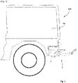
- a military vehicle 100 comprises a step device 1 secured to the rear of the vehicle 100 at the level of an access door to a passenger compartment 101 of the vehicle (door not visible).
- the running board device 1 comprises a frame 2 which makes it possible to secure the running board device 1 to the vehicle 100 by bolts 103.
- the frame 2 comprises two side wings 21 which extend substantially vertically under the vehicle and are secured to a first step 3 (only one wing 21 is visible in the figure).
- each wing 21 of the frame 1 carries a horizontal axis 4 intended to allow the pivoting of an arm 5 at the end of which there is a second step 6 which connects each arm 5 to each other.
- a single axis 4 connects the two wings 21.
- An arm 5 is attached to each end of the shaft 4 and the second step 6 is integral with the ends of the two arms 5.
- the axis 4 allows the second step 6 to pivot between a raised position as visible on the figure 1 where the second step 6 is located above a horizontal plane P passing through the axis 4, and a lowered position visible to the figure 3 and 4 .
- Each arm 5 has a lug 7, which is fixed to the arm 5 considered between the axis 4 and the second step 6.
- the locking device 8 comprises at least one finger 8a pivotally mounted on a pivot 12 relative to the frame 2.
- the finger 8a tilts against the action of an elastic means 10 (return spring). Note in the figures that the end of the finger 8a forms a hook 9 and the lug 7 carried by the arm 5 is intended to engage in this hook 9.
- the shape of the hook 9 is defined so as to hold the arm in the raised position by the action of the elastic means 10.
- the locking device 8 comprises a tab 11 secured to the finger 8a and the end 11a of which forms a projecting part which crosses the first step 3 by a slot.
- pressing the foot of personnel disembarking outside the vehicle (personnel not shown) on the projecting part 11a will cause the finger 8a to tilt against the action of the elastic means 10.
- the shape of the hook 9 is such that this tilting is sufficient to release the lug 7.
- the second step 6 is therefore unlocked and the arms 5 and the step 6 pivot around the axis 4 solely by the effect of gravity.
- a stop 13 which comprises a pair of flexible links 13 (one on each side of the second step 6) connecting the first step 3 to the second step 6.
- the links 13 make it possible to limit the angular movement of the second step and they therefore determine the lowered angular position where the second step 6 is located under the first step 3 and below the horizontal plane P passing through the axis 4.
- the second step 6 is then substantially horizontal and it allows easy disembarkation or embarkation from the vehicle 100 (vehicle visible at the figure 1 ).
- the step device 1 also includes a shock absorber 14 secured to the frame 2 and located between the frame 2 and at least one arm 5 when it is lowered.
- the damper 14 comprises a rod 14a which forms an abutment zone for a rear end 5a of the arm 5.
- a single damper 14 is sufficient at one of the arms 5.
- Damping will preferably take place over the few degrees (approximately 5°) from the end of the arm lowering pivot.
- the lowering movement of the second step 6 is not slowed down, but any sudden stopping of the arms 5 is avoided by the links 13 alone, which would harm the discretion of the lowering (noise due to the stopping shock) and eventually to the solidity of the device 1.
- the damper 14 is not integral with the arm 5 so as not to slow down the raising of the second step 6 from the lowered angular position to the raised angular position. This raising is done manually or by hooking the foot of the last boarding staff (staff not shown).
- the beveled shape 9a of the hook 9 allows an automatic locking movement of the arm 5.
- the lug 5 causes the finger 8a to pivot against the elastic means 10.
- the elastic means 10 brings the finger back and the hook 9 hooks the lug 7.
- the device resumes the configuration illustrated in figure 2 .
- the finger 8a comprises a guide profile 15 above the hook 9 which allows the raising of the lug 7 and therefore of the arm 5 beyond the raised position.
- the raised position of the second step 6 is therefore not a rigid position fixed by the hook 9 but rather a minimum raised position.
- the guide profile 15 therefore allows the raising of the lug 7 and of the arm 5 beyond the so-called raised angular position indicated in dotted lines PP on the figure 5 .
Landscapes
- Engineering & Computer Science (AREA)
- Mechanical Engineering (AREA)
- Vehicle Step Arrangements And Article Storage (AREA)
Description
- Le domaine technique de l'invention est celui des dispositifs de marchepied pliant pour l'embarquement et le débarquement à bord d'un véhicule.
- Afin de pouvoir aisément déplier le marchepied pour le placer dans une position dite d'accès, le brevet
EP2072337 décrit un marchepied comportant une marche équipée d'une partie saillante qui, lorsque l'on prend appui dessus, déclenche l'abaissement de la marche sous l'action d'un ressort à gaz. - Une fois la marche dépliée il faut alors relever celle-ci à la main pour la remettre en position relevée. On note que cette marche est solidaire d'un mécanisme de bielles articulées relativement à un bâti qui s'étend très bas sous la marche, quelle que soit la position de la marche. Un tel dispositif, au travers de son bâti notamment, est très exposé aux éventuels chocs avec le terrain sur lequel évolue le véhicule, en particulier dans le cas d'un véhicule tout terrain, ce qui risque de provoquer sa détérioration.
- Le document
US 3 807 757 concerne un dispositif de marchepied pour un véhicule selon la revendication 1. - L'invention propose un nouveau marchepied de structure simple et compatible des contraintes de franchissement et d'environnement dues à l'utilisation d'un véhicule en tout terrain.
- Ainsi, l'invention a pour objet un dispositif de marchepied pour un véhicule, dispositif comportant au moins une première marche solidaire d'un bâti destiné à être fixé au véhicule ainsi qu'au moins un bras comportant une seconde marche fixée au niveau d'une première extrémité du bras, bras monté pivotant relativement au bâti autour d'un axe horizontal entre une position angulaire dite relevée et une position angulaire dite abaissée dans laquelle la seconde marche est sensiblement horizontale, dispositif caractérisé en ce qu'il comporte un dispositif de verrouillage de la seconde marche en position relevée, une partie de ce dispositif de verrouillage étant en saillie au-dessus de la première marche de manière à ce qu'un appui sur la partie saillante déverrouille le dispositif de verrouillage afin que la seconde marche pivote jusqu'à sa position abaissée.
- Selon un mode de réalisation, le dispositif de verrouillage pourra comporter au moins un doigt monté basculant sur un pivot par rapport au bâti, contre l'action d'un moyen élastique, une extrémité du doigt formant un crochet et le bras comportant un ergot destiné à s'engager dans le crochet dont la forme est définie de façon à maintenir ainsi le bras en position relevée par l'action du moyen élastique, la partie saillante du dispositif de verrouillage étant solidaire du doigt et un appui exercé sur cette partie saillante faisant pivoter le doigt contre l'action du moyen élastique, ce qui permet d'abaisser le crochet dans une position permettant de libérer l'ergot.
- Avantageusement, le doigt pourra comporter un profil de guidage au-dessus du crochet autorisant la remontée de l'ergot et du bras au-delà de la position relevée.
- Selon un mode particulier de réalisation, le profil de guidage du doigt au-dessus du crochet pourra se terminer par une encoche assurant un maintien de l'ergot au-delà de la position relevée.
- Avantageusement, le dispositif pourra comporter une butée déterminant la position abaissée de la seconde marche.
- Selon un mode particulier de réalisation, la butée pourra comporter au moins un lien souple non élastique reliant le bras au bâti.
- Avantageusement, le dispositif pourra comporter au moins un amortisseur situé entre le bâti et le bras afin de limiter le choc du bras avec la butée lors de l'abaissement de la seconde marche.
- L'invention sera mieux comprise à la lecture de la description jointe, description faite au regard des dessins en annexe, dessins dans lesquels :
- [
Fig. 1 ] montre une vue schématique latérale d'un dispositif de marchepied selon l'invention en position relevée et solidaire d'un véhicule militaire. - [
Fig. 2 ] montre une vue schématique latérale d'un dispositif de marchepied selon l'invention en position relevée. - [
Fig. 3 ] montre une vue schématique latérale d'un dispositif de marchepied selon l'invention en position abaissée. - [
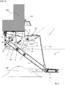
Fig. 4 ] montre une vue schématique latérale d'un dispositif de marchepied selon l'invention solidaire d'un véhicule militaire lors d'une opération de franchissement particulière. - [
Fig. 5 ] montre une vue agrandie du dispositif de marchepied selon lafigure 4 . - Selon la
figure 1 , un véhicule militaire 100 comporte un dispositif de marchepied 1 solidaire de l'arrière du véhicule 100 au niveau d'une porte d'accès à un habitacle 101 du véhicule (porte non visible). - Selon la
figure 2 , le dispositif de marchepied 1 comporte un bâti 2 qui permet de solidariser le dispositif de marchepied 1 au véhicule 100 par des boulons 103. Le bâti 2 comporte deux ailes latérales 21 qui s'étendent sensiblement verticalement sous le véhicule et sont solidaires d'une première marche 3 (une seule aile 21 est visible sur la figure). - L'extrémité de chaque aile 21 du bâti 1 porte un axe 4 horizontal destiné à permettre le pivotement d'un bras 5 à l'extrémité duquel se trouve une seconde marche 6 qui relie chaque bras 5 entre eux. Concrètement, pour la rigidité du dispositif, un seul axe 4 relie les deux ailes 21. Un bras 5 est fixé à chaque extrémité de l'axe 4 et la seconde marche 6 est solidaire des extrémités des deux bras 5.
- L'axe 4 permet à la seconde marche 6 de pivoter entre une position relevée telle que visible à la
figure 1 où la seconde marche 6 est située au-dessus d'un plan P horizontal passant par l'axe 4, et une position abaissée visible auxfigures 3 et4 . Chaque bras 5 comporte un ergot 7, qui est fixé au bras 5 considéré entre l'axe 4 et la seconde marche 6. - Le dispositif de verrouillage 8 comporte au moins un doigt 8a monté basculant sur un pivot 12 par rapport au bâti 2.
- Concrètement il y a un doigt 8a au niveau de chaque bras 5, donc à chaque extrémité de l'axe 4. Les
figures 2 ,3 et5 montrent donc une moitié du dispositif de marchepied 1 et de son dispositif de verrouillage 8. - Le doigt 8a bascule contre l'action d'un moyen élastique 10 (ressort de rappel). On remarque sur les figures que l'extrémité du doigt 8a forme un crochet 9 et l'ergot 7 porté par le bras 5 est destiné à s'engager dans ce crochet 9.
- La forme du crochet 9 est définie de façon à maintenir le bras en position relevée par l'action du moyen élastique 10.
- Le dispositif de verrouillage 8 comporte une languette 11 solidaire du doigt 8a et dont l'extrémité 11a forme une partie saillante qui traverse la première marche 3 par une fente. Ainsi un appui du pied d'un personnel débarquant hors du véhicule (personnel non représenté) sur la partie saillante 11a fera basculer le doigt 8a contre l'action du moyen élastique 10. La forme du crochet 9 est telle que ce basculement suffit à libérer l'ergot 7. La seconde marche 6 se trouve donc déverrouillée et les bras 5 et la marche 6 pivotent autour de l'axe 4 par le seul effet de la gravité.
- Selon la
figure 3 , consécutivement à l'abaissement de la seconde marche 6, celle-ci est arrêtée dans son mouvement par une butée 13 qui comporte une paire de liens souples 13 (un de chaque côté de la seconde marche 6) reliant la première marche 3 à la seconde marche 6. Les liens 13 permettent de limiter le débattement angulaire de la seconde marche et ils déterminent donc la position angulaire abaissée où la seconde marche 6 est située sous la première marche 3 et en dessous du plan horizontal P passant par l'axe 4. La seconde marche 6 est alors sensiblement horizontale et elle permet un débarquement ou un embarquement aisé depuis le véhicule 100 (véhicule visible à lafigure 1 ). - Selon un mode de réalisation, le dispositif de marchepied 1 comporte aussi un amortisseur 14 solidaire du bâti 2 et situé entre le bâti 2 et au moins un bras 5 lorsqu'il est abaissé. Comme on le voit à la
figure 3 , l'amortisseur 14 comporte une tige 14a qui vient former une zone de butée pour une extrémité arrière 5a du bras 5. Un seul amortisseur 14 suffit au niveau d'un des bras 5. - L'amortissement se fera préférentiellement sur les quelques degrés (environ 5°) de la fin du pivotement d'abaissement des bras. Ainsi on ne ralentit pas le mouvement d'abaissement de la seconde marche 6 mais on évite tout arrêt brutal des bras 5 par les seuls liens 13, ce qui nuirait à la discrétion de l'abaissement (bruit dû au choc d'arrêt) et à terme à la solidité du dispositif 1.
- L'amortisseur 14 n'est pas solidaire du bras 5 afin de ne pas ralentir le relevage de la seconde marche 6 de la position angulaire abaissée à la position angulaire relevée. Ce relèvement se fait manuellement ou par crochetage du pied du dernier personnel embarquant (personnel non représenté). La forme en biseau 9a du crochet 9 permet un mouvement de verrouillage automatique du bras 5. Lors du relèvement de la marche, l'ergot 5 fait pivoter le doigt 8a contre le moyen élastique 10. Une fois le biseau 9a franchi, le moyen élastique 10 fait revenir le doigt et le crochet 9 accroche l'ergot 7. Le dispositif reprend la configuration illustrée à la
figure 2 . - Il est à noter que, lorsque le véhicule avance (sens de la flèche AV), si un obstacle 200 vient à heurter les bras 5 ou la seconde marche 6, ils sont projetés vers le haut et avantageusement accrochés par inertie au dispositif de verrouillage 8. Il en est de même avec les éventuels soubresauts de roulement sur terrain accidentés et s'il a été oublié de relever la seconde marche 6 du marchepied 1.
- Pour cela, on note plus particulièrement aux
figures 4 et5 que le doigt 8a comporte un profil de guidage 15 au-dessus du crochet 9 qui autorise la remontée de l'ergot 7 et donc du bras 5 au-delà de la position relevée. La position relevée de la seconde marche 6 n'est donc pas une position rigide fixée par le crochet 9 mais plutôt une position relevée minimale. - Le profil de guidage 15 autorise donc la remontée de l'ergot 7 et du bras 5 au-delà de la position angulaire dite relevée indiqué en pointillés PP sur la
figure 5 . - Ainsi lors du franchissement d'une rupture abrupte de terrain 1000 par exemple, l'interférence de la seconde marche 6 ou des bras 5 avec le sol n'engendre pas de contraintes sur le dispositif de marchepied 1.
- On remarque par ailleurs sur les figures (et en particulier la
figure 5 ) que le profil de guidage 15 du doigt 8a au-dessus du crochet 9 se termine par une encoche 16 dans laquelle s'engage l'ergot 7. Cette encoche 16 est délimitée par un repli 17 du doigt 8a. L'encoche 16 assure donc un maintien de l'ergot 7 au-delà de la position relevée. Les doigts 8a et les bras 5 se trouvent donc solidaires de façon temporaire et il n'y a pas de décrochage de la seconde marche 6 lors de ce relèvement extrême. On évite ainsi la chute de la seconde marche en cas de choc tout terrain (rebond). - Lorsque le moyen élastique 10 fera basculer le doigt 8a, il ramènera le second doigt à sa position de la
figure 2 et la seconde marche 6 reprendra sa position relevée stable, retenue par les crochets 9 (figure 2 ). - L'homme du Métier déterminera la longueur L du profil de guidage 15 pouvant être parcourue par l'ergot 7 en fonction de l'amplitude angulaire au-delà de la position relevée qu'il souhaite donner à la seconde marche 6.
Claims (7)
- Dispositif de marchepied (1) pour un véhicule (100), dispositif comportant au moins une première marche (3) solidaire d'un bâti (2) destiné à être fixé au véhicule (100) ainsi qu'au moins un bras (5) comportant une seconde marche (6) fixée au niveau d'une première extrémité du bras (5), bras (5) monté pivotant relativement au bâti (2) autour d'un axe (4) horizontal entre une position angulaire dite relevée et une position angulaire dite abaissée dans laquelle la seconde marche (6) est sensiblement horizontale, dispositif (1) caractérisé en ce qu' il comporte un dispositif de verrouillage (8) de la seconde marche (6) en position relevée, une partie (11a) de ce dispositif de verrouillage (8) étant en saillie au-dessus de la première marche (3) de manière à ce qu'un appui sur la partie saillante (11a) déverrouille le dispositif de verrouillage (8) afin que la seconde marche (6) pivote jusqu'à sa position abaissée.
- Dispositif de marchepied (1) selon la revendication 1, caractérisé en ce que le dispositif de verrouillage (8) comporte au moins un doigt (8a) monté basculant sur un pivot (12) par rapport au bâti (2), contre l'action d'un moyen élastique (10), une extrémité du doigt (8a) formant un crochet (9) et le bras (5) comportant un ergot (7) destiné à s'engager dans le crochet (9) dont la forme est définie de façon à maintenir ainsi le bras en position relevée par l'action du moyen élastique (10), la partie saillante (11a) du dispositif de verrouillage (8) étant solidaire du doigt (8a) et un appui exercé sur cette partie saillante faisant pivoter le doigt (8a) contre l'action du moyen élastique (10), ce qui permet d'abaisser le crochet (9) dans une position permettant de libérer l'ergot (7).
- Dispositif de marchepied (1) selon la revendication 2, caractérisé en ce que le doigt (8a) comporte un profil de guidage (15) au-dessus du crochet (9) autorisant la remontée de l'ergot (7) et du bras (5) au-delà de la position relevée.
- Dispositif de marchepied (1) selon la revendication 3, caractérisé en ce que le profil de guidage (15) du doigt au-dessus du crochet (9) se termine par une encoche (16) assurant un maintien de l'ergot (7) au-delà de la position relevée.
- Dispositif selon l'une des revendications 1 à 4, caractérisé en ce qu'il comporte une butée (13) déterminant la position abaissée de la seconde marche (6).
- Dispositif (1) selon la revendication 5, caractérisé en ce que la butée (13) comporte au moins un lien souple (13) non élastique reliant le bras (5) au bâti (2).
- Dispositif (1) selon une des revendications 5 ou 6, caractérisé en ce qu'il comporte au moins un amortisseur (14) situé entre le bâti (2) et le bras (5) afin de limiter le choc du bras (5) avec la butée (13) lors de l'abaissement de la seconde marche (6).
Applications Claiming Priority (1)
| Application Number | Priority Date | Filing Date | Title |
|---|---|---|---|
| FR2000770A FR3106547B1 (fr) | 2020-01-28 | 2020-01-28 | Dispositif de marchepied pour véhicule |
Publications (2)
| Publication Number | Publication Date |
|---|---|
| EP3858677A1 EP3858677A1 (fr) | 2021-08-04 |
| EP3858677B1 true EP3858677B1 (fr) | 2022-11-02 |
Family
ID=71094448
Family Applications (1)
| Application Number | Title | Priority Date | Filing Date |
|---|---|---|---|
| EP20213006.8A Active EP3858677B1 (fr) | 2020-01-28 | 2020-12-10 | Dispositif de marchepied pour véhicule |
Country Status (3)
| Country | Link |
|---|---|
| EP (1) | EP3858677B1 (fr) |
| ES (1) | ES2933449T3 (fr) |
| FR (1) | FR3106547B1 (fr) |
Citations (1)
| Publication number | Priority date | Publication date | Assignee | Title |
|---|---|---|---|---|
| US5941342A (en) * | 1997-07-07 | 1999-08-24 | Apc Industrial Co., Ltd. | Folding staircase |
Family Cites Families (11)
| Publication number | Priority date | Publication date | Assignee | Title |
|---|---|---|---|---|
| US608617A (en) * | 1898-08-09 | Thomas millen | ||
| US2246986A (en) * | 1939-09-02 | 1941-06-24 | Virgil Mccombs | Folding step for trucks |
| DE1220276B (de) * | 1960-09-09 | 1966-06-30 | Ford Werke Ag | Ausschwingbare Trittstufe fuer Kraftfahrzeuge |
| US3807757A (en) * | 1972-05-22 | 1974-04-30 | H Carpenter | Folding steps for campers and the like |
| US3889997A (en) * | 1974-02-25 | 1975-06-17 | Clarence E Schoneck | Automatically operating truck end gate steps |
| SU783097A1 (ru) * | 1978-10-06 | 1980-11-30 | Предприятие П/Я А-1373 | Убирающа с подножка транспортного средства |
| IT1259621B (it) * | 1992-03-03 | 1996-03-25 | Dispositivo attuatore della rotazione di una scaletta per veicoli. | |
| US7168722B1 (en) * | 2004-08-23 | 2007-01-30 | Piotrowski Leo D | Pull-out step assembly for a pickup truck |
| US7744106B2 (en) | 2006-06-02 | 2010-06-29 | Ford Global Technologies | Vehicle step with hinged pedestal mount |
| JP6322104B2 (ja) * | 2014-09-22 | 2018-05-09 | 和光工業株式会社 | 車両乗降用自動二段ステップ装置 |
| GB2535442A (en) * | 2015-01-12 | 2016-08-24 | Stuart Hickie Taylor William | Retractable tread two tread flip step |
-
2020
- 2020-01-28 FR FR2000770A patent/FR3106547B1/fr active Active
- 2020-12-10 ES ES20213006T patent/ES2933449T3/es active Active
- 2020-12-10 EP EP20213006.8A patent/EP3858677B1/fr active Active
Patent Citations (1)
| Publication number | Priority date | Publication date | Assignee | Title |
|---|---|---|---|---|
| US5941342A (en) * | 1997-07-07 | 1999-08-24 | Apc Industrial Co., Ltd. | Folding staircase |
Also Published As
| Publication number | Publication date |
|---|---|
| FR3106547A1 (fr) | 2021-07-30 |
| FR3106547B1 (fr) | 2021-12-31 |
| ES2933449T3 (es) | 2023-02-09 |
| EP3858677A1 (fr) | 2021-08-04 |
Similar Documents
| Publication | Publication Date | Title |
|---|---|---|
| EP1721827B1 (fr) | Procédé et système anti-crash, atterrisseur et aéronef | |
| FR2931403A1 (fr) | Dispositif d'absorption de choc et siege comportant un tel dispositif | |
| EP0533531A1 (fr) | Train de roulage rétractable pour un véhicule à sustentation sans contact | |
| EP1340676A1 (fr) | Train d'atterrissage d'aéronef à système autonome de carénage aéroacoustique | |
| EP3619114B1 (fr) | Siège muni d'un système de verrouillage de tablette en cas de choc | |
| EP3858677B1 (fr) | Dispositif de marchepied pour véhicule | |
| FR2688190A1 (fr) | Train d'atterrissage relevable. | |
| EP2330010B1 (fr) | Siège pour une installation teléportée | |
| EP0041016A1 (fr) | Tablette de rangement s'escamotant automatiquement | |
| EP3720769B1 (fr) | Dispositif d'accrochage comportant un système de rappel pour crochet de charge | |
| EP0508923B1 (fr) | Dispositif de décrochage d'ancre | |
| EP1564138B1 (fr) | Echelle de communication entre un niveau supérieur et un niveau inférieur d'un aéronef, et aéronef muni d'une telle échelle | |
| EP0950001B1 (fr) | Agencement pour l'acces a la partie arriere de l'habitacle d'un vehicule automobile | |
| FR3087414A1 (fr) | Porte d'aeronef a soulevement supplementaire de securite | |
| EP3463988B1 (fr) | Dispositif de fixation et marchepied equipe d'un tel dispositif | |
| EP2992293B1 (fr) | Véhicule équipé d'un dispositif de protection d'ouvrant assurant une optimisation du gabarit d'ouverture | |
| EP3649015B1 (fr) | Vehicule automobile dote d'une cloison d'arret de charge et comprenant un dispositif de retenue d'un dossier de siege | |
| EP2857260B1 (fr) | Siège pour véhicule militaire | |
| EP3354831B1 (fr) | Coffre pour le transport et le débarquement de robot | |
| EP3233565B1 (fr) | Siege escamotable | |
| FR2609948A1 (fr) | Dispositif de verrouillage a inertie pour siege de vehicule | |
| EP2977536B1 (fr) | Véhicule équipé d'un dispositif de compensation de poids d'une trappe | |
| FR2997663A1 (fr) | Nacelle deformable pour vehicule | |
| EP4281360A1 (fr) | Procédé et ensemble de guidage stabilisateur de porte de véhicule à verrouillage de bielle | |
| FR2637850A1 (fr) | Pare-soleil pour vehicule automobile |
Legal Events
| Date | Code | Title | Description |
|---|---|---|---|
| PUAI | Public reference made under article 153(3) epc to a published international application that has entered the european phase |
Free format text: ORIGINAL CODE: 0009012 |
|
| STAA | Information on the status of an ep patent application or granted ep patent |
Free format text: STATUS: THE APPLICATION HAS BEEN PUBLISHED |
|
| AK | Designated contracting states |
Kind code of ref document: A1 Designated state(s): AL AT BE BG CH CY CZ DE DK EE ES FI FR GB GR HR HU IE IS IT LI LT LU LV MC MK MT NL NO PL PT RO RS SE SI SK SM TR |
|
| STAA | Information on the status of an ep patent application or granted ep patent |
Free format text: STATUS: REQUEST FOR EXAMINATION WAS MADE |
|
| 17P | Request for examination filed |
Effective date: 20220204 |
|
| RBV | Designated contracting states (corrected) |
Designated state(s): AL AT BE BG CH CY CZ DE DK EE ES FI FR GB GR HR HU IE IS IT LI LT LU LV MC MK MT NL NO PL PT RO RS SE SI SK SM TR |
|
| GRAP | Despatch of communication of intention to grant a patent |
Free format text: ORIGINAL CODE: EPIDOSNIGR1 |
|
| STAA | Information on the status of an ep patent application or granted ep patent |
Free format text: STATUS: GRANT OF PATENT IS INTENDED |
|
| INTG | Intention to grant announced |
Effective date: 20220706 |
|
| GRAS | Grant fee paid |
Free format text: ORIGINAL CODE: EPIDOSNIGR3 |
|
| GRAA | (expected) grant |
Free format text: ORIGINAL CODE: 0009210 |
|
| STAA | Information on the status of an ep patent application or granted ep patent |
Free format text: STATUS: THE PATENT HAS BEEN GRANTED |
|
| AK | Designated contracting states |
Kind code of ref document: B1 Designated state(s): AL AT BE BG CH CY CZ DE DK EE ES FI FR GB GR HR HU IE IS IT LI LT LU LV MC MK MT NL NO PL PT RO RS SE SI SK SM TR |
|
| REG | Reference to a national code |
Ref country code: GB Ref legal event code: FG4D Free format text: NOT ENGLISH |
|
| REG | Reference to a national code |
Ref country code: CH Ref legal event code: EP Ref country code: AT Ref legal event code: REF Ref document number: 1528541 Country of ref document: AT Kind code of ref document: T Effective date: 20221115 |
|
| REG | Reference to a national code |
Ref country code: DE Ref legal event code: R096 Ref document number: 602020006040 Country of ref document: DE |
|
| REG | Reference to a national code |
Ref country code: IE Ref legal event code: FG4D Free format text: LANGUAGE OF EP DOCUMENT: FRENCH |
|
| REG | Reference to a national code |
Ref country code: SE Ref legal event code: TRGR |
|
| REG | Reference to a national code |
Ref country code: NL Ref legal event code: FP |
|
| REG | Reference to a national code |
Ref country code: ES Ref legal event code: FG2A Ref document number: 2933449 Country of ref document: ES Kind code of ref document: T3 Effective date: 20230209 |
|
| REG | Reference to a national code |
Ref country code: LT Ref legal event code: MG9D |
|
| REG | Reference to a national code |
Ref country code: AT Ref legal event code: MK05 Ref document number: 1528541 Country of ref document: AT Kind code of ref document: T Effective date: 20221102 |
|
| PG25 | Lapsed in a contracting state [announced via postgrant information from national office to epo] |
Ref country code: PT Free format text: LAPSE BECAUSE OF FAILURE TO SUBMIT A TRANSLATION OF THE DESCRIPTION OR TO PAY THE FEE WITHIN THE PRESCRIBED TIME-LIMIT Effective date: 20230302 Ref country code: NO Free format text: LAPSE BECAUSE OF FAILURE TO SUBMIT A TRANSLATION OF THE DESCRIPTION OR TO PAY THE FEE WITHIN THE PRESCRIBED TIME-LIMIT Effective date: 20230202 Ref country code: LT Free format text: LAPSE BECAUSE OF FAILURE TO SUBMIT A TRANSLATION OF THE DESCRIPTION OR TO PAY THE FEE WITHIN THE PRESCRIBED TIME-LIMIT Effective date: 20221102 Ref country code: FI Free format text: LAPSE BECAUSE OF FAILURE TO SUBMIT A TRANSLATION OF THE DESCRIPTION OR TO PAY THE FEE WITHIN THE PRESCRIBED TIME-LIMIT Effective date: 20221102 Ref country code: AT Free format text: LAPSE BECAUSE OF FAILURE TO SUBMIT A TRANSLATION OF THE DESCRIPTION OR TO PAY THE FEE WITHIN THE PRESCRIBED TIME-LIMIT Effective date: 20221102 |
|
| PG25 | Lapsed in a contracting state [announced via postgrant information from national office to epo] |
Ref country code: RS Free format text: LAPSE BECAUSE OF FAILURE TO SUBMIT A TRANSLATION OF THE DESCRIPTION OR TO PAY THE FEE WITHIN THE PRESCRIBED TIME-LIMIT Effective date: 20221102 Ref country code: PL Free format text: LAPSE BECAUSE OF FAILURE TO SUBMIT A TRANSLATION OF THE DESCRIPTION OR TO PAY THE FEE WITHIN THE PRESCRIBED TIME-LIMIT Effective date: 20221102 Ref country code: LV Free format text: LAPSE BECAUSE OF FAILURE TO SUBMIT A TRANSLATION OF THE DESCRIPTION OR TO PAY THE FEE WITHIN THE PRESCRIBED TIME-LIMIT Effective date: 20221102 Ref country code: IS Free format text: LAPSE BECAUSE OF FAILURE TO SUBMIT A TRANSLATION OF THE DESCRIPTION OR TO PAY THE FEE WITHIN THE PRESCRIBED TIME-LIMIT Effective date: 20230302 Ref country code: HR Free format text: LAPSE BECAUSE OF FAILURE TO SUBMIT A TRANSLATION OF THE DESCRIPTION OR TO PAY THE FEE WITHIN THE PRESCRIBED TIME-LIMIT Effective date: 20221102 Ref country code: GR Free format text: LAPSE BECAUSE OF FAILURE TO SUBMIT A TRANSLATION OF THE DESCRIPTION OR TO PAY THE FEE WITHIN THE PRESCRIBED TIME-LIMIT Effective date: 20230203 |
|
| PG25 | Lapsed in a contracting state [announced via postgrant information from national office to epo] |
Ref country code: SM Free format text: LAPSE BECAUSE OF FAILURE TO SUBMIT A TRANSLATION OF THE DESCRIPTION OR TO PAY THE FEE WITHIN THE PRESCRIBED TIME-LIMIT Effective date: 20221102 Ref country code: RO Free format text: LAPSE BECAUSE OF FAILURE TO SUBMIT A TRANSLATION OF THE DESCRIPTION OR TO PAY THE FEE WITHIN THE PRESCRIBED TIME-LIMIT Effective date: 20221102 Ref country code: IT Free format text: LAPSE BECAUSE OF NON-PAYMENT OF DUE FEES Effective date: 20221210 Ref country code: EE Free format text: LAPSE BECAUSE OF FAILURE TO SUBMIT A TRANSLATION OF THE DESCRIPTION OR TO PAY THE FEE WITHIN THE PRESCRIBED TIME-LIMIT Effective date: 20221102 Ref country code: DK Free format text: LAPSE BECAUSE OF FAILURE TO SUBMIT A TRANSLATION OF THE DESCRIPTION OR TO PAY THE FEE WITHIN THE PRESCRIBED TIME-LIMIT Effective date: 20221102 |
|
| REG | Reference to a national code |
Ref country code: DE Ref legal event code: R097 Ref document number: 602020006040 Country of ref document: DE |
|
| REG | Reference to a national code |
Ref country code: BE Ref legal event code: MM Effective date: 20221231 |
|
| PG25 | Lapsed in a contracting state [announced via postgrant information from national office to epo] |
Ref country code: SK Free format text: LAPSE BECAUSE OF FAILURE TO SUBMIT A TRANSLATION OF THE DESCRIPTION OR TO PAY THE FEE WITHIN THE PRESCRIBED TIME-LIMIT Effective date: 20221102 Ref country code: LU Free format text: LAPSE BECAUSE OF NON-PAYMENT OF DUE FEES Effective date: 20221210 Ref country code: AL Free format text: LAPSE BECAUSE OF FAILURE TO SUBMIT A TRANSLATION OF THE DESCRIPTION OR TO PAY THE FEE WITHIN THE PRESCRIBED TIME-LIMIT Effective date: 20221102 |
|
| PLBE | No opposition filed within time limit |
Free format text: ORIGINAL CODE: 0009261 |
|
| STAA | Information on the status of an ep patent application or granted ep patent |
Free format text: STATUS: NO OPPOSITION FILED WITHIN TIME LIMIT |
|
| 26N | No opposition filed |
Effective date: 20230803 |
|
| PG25 | Lapsed in a contracting state [announced via postgrant information from national office to epo] |
Ref country code: IE Free format text: LAPSE BECAUSE OF NON-PAYMENT OF DUE FEES Effective date: 20221210 |
|
| PG25 | Lapsed in a contracting state [announced via postgrant information from national office to epo] |
Ref country code: SI Free format text: LAPSE BECAUSE OF FAILURE TO SUBMIT A TRANSLATION OF THE DESCRIPTION OR TO PAY THE FEE WITHIN THE PRESCRIBED TIME-LIMIT Effective date: 20221102 Ref country code: BE Free format text: LAPSE BECAUSE OF NON-PAYMENT OF DUE FEES Effective date: 20221231 |
|
| PGFP | Annual fee paid to national office [announced via postgrant information from national office to epo] |
Ref country code: NL Payment date: 20231121 Year of fee payment: 4 |
|
| PG25 | Lapsed in a contracting state [announced via postgrant information from national office to epo] |
Ref country code: IT Free format text: LAPSE BECAUSE OF NON-PAYMENT OF DUE FEES Effective date: 20221210 |
|
| PGFP | Annual fee paid to national office [announced via postgrant information from national office to epo] |
Ref country code: SE Payment date: 20231121 Year of fee payment: 4 Ref country code: IT Payment date: 20221231 Year of fee payment: 3 Ref country code: FR Payment date: 20231122 Year of fee payment: 4 Ref country code: DE Payment date: 20231121 Year of fee payment: 4 Ref country code: CZ Payment date: 20231124 Year of fee payment: 4 |
|
| PGRI | Patent reinstated in contracting state [announced from national office to epo] |
Ref country code: IT Effective date: 20221231 |
|
| PGFP | Annual fee paid to national office [announced via postgrant information from national office to epo] |
Ref country code: ES Payment date: 20240102 Year of fee payment: 4 |
|
| PG25 | Lapsed in a contracting state [announced via postgrant information from national office to epo] |
Ref country code: CY Free format text: LAPSE BECAUSE OF FAILURE TO SUBMIT A TRANSLATION OF THE DESCRIPTION OR TO PAY THE FEE WITHIN THE PRESCRIBED TIME-LIMIT Effective date: 20221102 |