EP3417227B1 - Heat exchanger, in particular water-air heat exchanger or oil-water heat exchanger - Google Patents
Heat exchanger, in particular water-air heat exchanger or oil-water heat exchanger Download PDFInfo
- Publication number
- EP3417227B1 EP3417227B1 EP17707776.5A EP17707776A EP3417227B1 EP 3417227 B1 EP3417227 B1 EP 3417227B1 EP 17707776 A EP17707776 A EP 17707776A EP 3417227 B1 EP3417227 B1 EP 3417227B1
- Authority
- EP
- European Patent Office
- Prior art keywords
- heat exchanger
- fluid
- water
- oil
- receiving volume
- Prior art date
- Legal status (The legal status is an assumption and is not a legal conclusion. Google has not performed a legal analysis and makes no representation as to the accuracy of the status listed.)
- Active
Links
- XLYOFNOQVPJJNP-UHFFFAOYSA-N water Substances O XLYOFNOQVPJJNP-UHFFFAOYSA-N 0.000 title claims description 42
- 239000012530 fluid Substances 0.000 claims description 79
- 238000000576 coating method Methods 0.000 claims description 50
- 239000011248 coating agent Substances 0.000 claims description 47
- 238000004519 manufacturing process Methods 0.000 claims description 7
- 238000002485 combustion reaction Methods 0.000 claims description 4
- 238000005485 electric heating Methods 0.000 claims 4
- 239000000470 constituent Substances 0.000 claims 2
- 238000010438 heat treatment Methods 0.000 description 61
- 239000010410 layer Substances 0.000 description 27
- 239000003921 oil Substances 0.000 description 12
- 238000000034 method Methods 0.000 description 9
- 238000009413 insulation Methods 0.000 description 7
- PXHVJJICTQNCMI-UHFFFAOYSA-N Nickel Chemical compound [Ni] PXHVJJICTQNCMI-UHFFFAOYSA-N 0.000 description 6
- 230000000873 masking effect Effects 0.000 description 5
- 239000004020 conductor Substances 0.000 description 4
- 239000000758 substrate Substances 0.000 description 4
- VYZAMTAEIAYCRO-UHFFFAOYSA-N Chromium Chemical compound [Cr] VYZAMTAEIAYCRO-UHFFFAOYSA-N 0.000 description 3
- 229910010293 ceramic material Inorganic materials 0.000 description 3
- 229910052804 chromium Inorganic materials 0.000 description 3
- 239000011651 chromium Substances 0.000 description 3
- 239000000463 material Substances 0.000 description 3
- 229910052759 nickel Inorganic materials 0.000 description 3
- 229910018072 Al 2 O 3 Inorganic materials 0.000 description 2
- 238000007743 anodising Methods 0.000 description 2
- 239000002826 coolant Substances 0.000 description 2
- 238000001816 cooling Methods 0.000 description 2
- 239000007788 liquid Substances 0.000 description 2
- 239000010705 motor oil Substances 0.000 description 2
- 238000002161 passivation Methods 0.000 description 2
- 239000002861 polymer material Substances 0.000 description 2
- 229920001296 polysiloxane Polymers 0.000 description 2
- 230000002195 synergetic effect Effects 0.000 description 2
- 229910000838 Al alloy Inorganic materials 0.000 description 1
- 239000002318 adhesion promoter Substances 0.000 description 1
- 229910052782 aluminium Inorganic materials 0.000 description 1
- XAGFODPZIPBFFR-UHFFFAOYSA-N aluminium Chemical compound [Al] XAGFODPZIPBFFR-UHFFFAOYSA-N 0.000 description 1
- 230000001276 controlling effect Effects 0.000 description 1
- 230000000694 effects Effects 0.000 description 1
- 238000010292 electrical insulation Methods 0.000 description 1
- 239000003344 environmental pollutant Substances 0.000 description 1
- 238000007654 immersion Methods 0.000 description 1
- 239000012212 insulator Substances 0.000 description 1
- 229910052751 metal Inorganic materials 0.000 description 1
- 239000002184 metal Substances 0.000 description 1
- 230000003647 oxidation Effects 0.000 description 1
- 238000007254 oxidation reaction Methods 0.000 description 1
- 230000001590 oxidative effect Effects 0.000 description 1
- 238000010422 painting Methods 0.000 description 1
- 238000007750 plasma spraying Methods 0.000 description 1
- 231100000719 pollutant Toxicity 0.000 description 1
- 230000001681 protective effect Effects 0.000 description 1
- 239000011241 protective layer Substances 0.000 description 1
- 230000001105 regulatory effect Effects 0.000 description 1
- 238000007650 screen-printing Methods 0.000 description 1
Images

Classifications
-
- F—MECHANICAL ENGINEERING; LIGHTING; HEATING; WEAPONS; BLASTING
- F24—HEATING; RANGES; VENTILATING
- F24D—DOMESTIC- OR SPACE-HEATING SYSTEMS, e.g. CENTRAL HEATING SYSTEMS; DOMESTIC HOT-WATER SUPPLY SYSTEMS; ELEMENTS OR COMPONENTS THEREFOR
- F24D13/00—Electric heating systems
- F24D13/04—Electric heating systems using electric heating of heat-transfer fluid in separate units of the system
-
- F—MECHANICAL ENGINEERING; LIGHTING; HEATING; WEAPONS; BLASTING
- F24—HEATING; RANGES; VENTILATING
- F24H—FLUID HEATERS, e.g. WATER OR AIR HEATERS, HAVING HEAT-GENERATING MEANS, e.g. HEAT PUMPS, IN GENERAL
- F24H9/00—Details
- F24H9/18—Arrangement or mounting of grates or heating means
- F24H9/1809—Arrangement or mounting of grates or heating means for water heaters
- F24H9/1818—Arrangement or mounting of electric heating means
-
- F—MECHANICAL ENGINEERING; LIGHTING; HEATING; WEAPONS; BLASTING
- F28—HEAT EXCHANGE IN GENERAL
- F28F—DETAILS OF HEAT-EXCHANGE AND HEAT-TRANSFER APPARATUS, OF GENERAL APPLICATION
- F28F13/00—Arrangements for modifying heat-transfer, e.g. increasing, decreasing
-
- F—MECHANICAL ENGINEERING; LIGHTING; HEATING; WEAPONS; BLASTING
- F28—HEAT EXCHANGE IN GENERAL
- F28F—DETAILS OF HEAT-EXCHANGE AND HEAT-TRANSFER APPARATUS, OF GENERAL APPLICATION
- F28F13/00—Arrangements for modifying heat-transfer, e.g. increasing, decreasing
- F28F13/18—Arrangements for modifying heat-transfer, e.g. increasing, decreasing by applying coatings, e.g. radiation-absorbing, radiation-reflecting; by surface treatment, e.g. polishing
-
- F—MECHANICAL ENGINEERING; LIGHTING; HEATING; WEAPONS; BLASTING
- F24—HEATING; RANGES; VENTILATING
- F24H—FLUID HEATERS, e.g. WATER OR AIR HEATERS, HAVING HEAT-GENERATING MEANS, e.g. HEAT PUMPS, IN GENERAL
- F24H2250/00—Electrical heat generating means
- F24H2250/02—Resistances
-
- F—MECHANICAL ENGINEERING; LIGHTING; HEATING; WEAPONS; BLASTING
- F28—HEAT EXCHANGE IN GENERAL
- F28D—HEAT-EXCHANGE APPARATUS, NOT PROVIDED FOR IN ANOTHER SUBCLASS, IN WHICH THE HEAT-EXCHANGE MEDIA DO NOT COME INTO DIRECT CONTACT
- F28D1/00—Heat-exchange apparatus having stationary conduit assemblies for one heat-exchange medium only, the media being in contact with different sides of the conduit wall, in which the other heat-exchange medium is a large body of fluid, e.g. domestic or motor car radiators
- F28D1/02—Heat-exchange apparatus having stationary conduit assemblies for one heat-exchange medium only, the media being in contact with different sides of the conduit wall, in which the other heat-exchange medium is a large body of fluid, e.g. domestic or motor car radiators with heat-exchange conduits immersed in the body of fluid
- F28D1/04—Heat-exchange apparatus having stationary conduit assemblies for one heat-exchange medium only, the media being in contact with different sides of the conduit wall, in which the other heat-exchange medium is a large body of fluid, e.g. domestic or motor car radiators with heat-exchange conduits immersed in the body of fluid with tubular conduits
- F28D1/053—Heat-exchange apparatus having stationary conduit assemblies for one heat-exchange medium only, the media being in contact with different sides of the conduit wall, in which the other heat-exchange medium is a large body of fluid, e.g. domestic or motor car radiators with heat-exchange conduits immersed in the body of fluid with tubular conduits the conduits being straight
- F28D1/05316—Assemblies of conduits connected to common headers, e.g. core type radiators
-
- F—MECHANICAL ENGINEERING; LIGHTING; HEATING; WEAPONS; BLASTING
- F28—HEAT EXCHANGE IN GENERAL
- F28D—HEAT-EXCHANGE APPARATUS, NOT PROVIDED FOR IN ANOTHER SUBCLASS, IN WHICH THE HEAT-EXCHANGE MEDIA DO NOT COME INTO DIRECT CONTACT
- F28D21/00—Heat-exchange apparatus not covered by any of the groups F28D1/00 - F28D20/00
- F28D2021/0019—Other heat exchangers for particular applications; Heat exchange systems not otherwise provided for
- F28D2021/008—Other heat exchangers for particular applications; Heat exchange systems not otherwise provided for for vehicles
- F28D2021/0089—Oil coolers
-
- F—MECHANICAL ENGINEERING; LIGHTING; HEATING; WEAPONS; BLASTING
- F28—HEAT EXCHANGE IN GENERAL
- F28D—HEAT-EXCHANGE APPARATUS, NOT PROVIDED FOR IN ANOTHER SUBCLASS, IN WHICH THE HEAT-EXCHANGE MEDIA DO NOT COME INTO DIRECT CONTACT
- F28D21/00—Heat-exchange apparatus not covered by any of the groups F28D1/00 - F28D20/00
- F28D2021/0019—Other heat exchangers for particular applications; Heat exchange systems not otherwise provided for
- F28D2021/008—Other heat exchangers for particular applications; Heat exchange systems not otherwise provided for for vehicles
- F28D2021/0091—Radiators
- F28D2021/0094—Radiators for recooling the engine coolant
-
- F—MECHANICAL ENGINEERING; LIGHTING; HEATING; WEAPONS; BLASTING
- F28—HEAT EXCHANGE IN GENERAL
- F28D—HEAT-EXCHANGE APPARATUS, NOT PROVIDED FOR IN ANOTHER SUBCLASS, IN WHICH THE HEAT-EXCHANGE MEDIA DO NOT COME INTO DIRECT CONTACT
- F28D9/00—Heat-exchange apparatus having stationary plate-like or laminated conduit assemblies for both heat-exchange media, the media being in contact with different sides of a conduit wall
- F28D9/0031—Heat-exchange apparatus having stationary plate-like or laminated conduit assemblies for both heat-exchange media, the media being in contact with different sides of a conduit wall the conduits for one heat-exchange medium being formed by paired plates touching each other
- F28D9/0043—Heat-exchange apparatus having stationary plate-like or laminated conduit assemblies for both heat-exchange media, the media being in contact with different sides of a conduit wall the conduits for one heat-exchange medium being formed by paired plates touching each other the plates having openings therein for circulation of at least one heat-exchange medium from one conduit to another
- F28D9/005—Heat-exchange apparatus having stationary plate-like or laminated conduit assemblies for both heat-exchange media, the media being in contact with different sides of a conduit wall the conduits for one heat-exchange medium being formed by paired plates touching each other the plates having openings therein for circulation of at least one heat-exchange medium from one conduit to another the plates having openings therein for both heat-exchange media
-
- F—MECHANICAL ENGINEERING; LIGHTING; HEATING; WEAPONS; BLASTING
- F28—HEAT EXCHANGE IN GENERAL
- F28F—DETAILS OF HEAT-EXCHANGE AND HEAT-TRANSFER APPARATUS, OF GENERAL APPLICATION
- F28F9/00—Casings; Header boxes; Auxiliary supports for elements; Auxiliary members within casings
- F28F9/02—Header boxes; End plates
-
- H—ELECTRICITY
- H05—ELECTRIC TECHNIQUES NOT OTHERWISE PROVIDED FOR
- H05B—ELECTRIC HEATING; ELECTRIC LIGHT SOURCES NOT OTHERWISE PROVIDED FOR; CIRCUIT ARRANGEMENTS FOR ELECTRIC LIGHT SOURCES, IN GENERAL
- H05B2203/00—Aspects relating to Ohmic resistive heating covered by group H05B3/00
- H05B2203/013—Heaters using resistive films or coatings
-
- H—ELECTRICITY
- H05—ELECTRIC TECHNIQUES NOT OTHERWISE PROVIDED FOR
- H05B—ELECTRIC HEATING; ELECTRIC LIGHT SOURCES NOT OTHERWISE PROVIDED FOR; CIRCUIT ARRANGEMENTS FOR ELECTRIC LIGHT SOURCES, IN GENERAL
- H05B3/00—Ohmic-resistance heating
- H05B3/10—Heater elements characterised by the composition or nature of the materials or by the arrangement of the conductor
- H05B3/12—Heater elements characterised by the composition or nature of the materials or by the arrangement of the conductor characterised by the composition or nature of the conductive material
Definitions
- the invention relates to a heat exchanger, in particular a water-air heat exchanger or an oil-water heat exchanger according to claim 1, and a method for producing a heat exchanger, in particular a water-air heat exchanger or an oil-water heat exchanger according to claim 6.
- EP 2 466 241 A1 describes an oil-water heat exchanger with several pan elements stacked on top of one another and soldered together.
- Such oil-water heat exchangers are usually integrated into the cooling circuit of internal combustion engines and can be used, for example, to cool the engine oil.
- an electric heater is proposed there in an interior space of the heat exchanger in order to heat one of the interacting fluids of the heat exchanger.
- DE 10 2013 010 907 A1 shows an electrical heating device for heating a first medium and a second medium according to the preamble of claim 1, comprising at least one pipe carrying the second medium, a heat exchanger which is in thermally conductive contact with the at least one pipe and which carries the first medium, and a Layer heating element that at least partially covers the surface of the at least one tube.
- FR 2 966 580 A1 shows a heat exchanger which has a collector box for receiving a coolant and a radiator in which the coolant is circulated.
- the collector box contains an electrical heating element, for example an electric immersion heater, which is provided with an active part which extends into an internal volume defined by the collector box.
- heaters are described that have an electrical heating layer that heats up when an electrical voltage is applied (or when a current flows).
- DE 10 2011 006 248 A1 A household refrigerator with a heating device is described there.
- the heating device is produced as a layer heater by painting and applied to a surface of an evaporator of the household refrigerator.
- the stratified heating is according to DE 10 2011 006 248 A1 Directly applied over a surface of the evaporator and hardly thermally insulating in order to impair the functionality of the evaporator as little as possible.
- it is considered to be disadvantageous that the production according to this prior art is comparatively complex and appears to be tailored to a very special application. It is the object of the invention to propose a heat exchanger which enables a fluid flowing through the heat exchanger to be heated in a simple and effective manner.
- a heat exchanger in particular water-air heat exchanger or oil-water heat exchanger, comprising at least one first fluid channel for guiding a first fluid (e.g. oil from an oil-water heat exchanger or water from a water-air heat exchanger ), as well as at least one second fluid channel for guiding a second fluid (e.g. water of the oil-water heat exchanger or air of the water-air heat exchanger), the at least one first fluid channel being connected to a fluid receiving volume (in particular the outlet side), the fluid receiving volume is equipped with an electrical heating coating, wherein the fluid receiving volume is provided by a separate module, wherein the separate module can be or is attached to the remaining components of the heat exchanger.
- the heat exchanger can generally be a liquid-liquid heat exchanger or a liquid-gas heat exchanger or a gas-gas heat exchanger.
- a core idea of the invention is that of the per se, for example WO 2013/186106 A1 or WO 2013/030048 A1 known electrical heating coatings to apply to a fluid receiving volume which is connected to at least one of the fluid channels.
- a fluid to be heated with the heat exchanger can effectively be additionally heated or the temperature of a heating fluid can be increased further (in particular if the electrical heating coating is connected on the inlet side to a fluid channel of the heating fluid).
- a fluid can be effectively heated, for example an oil of an oil-water heat exchanger for an internal combustion engine of a motor vehicle can be heated.
- the heat exchanger can have several first fluid channels and / or several second fluid channels.
- the fluid receiving volume is a volume of the heat exchanger before (or after) the fluid is distributed to a plurality of individual fluid channels (that is to say, for example, a fluid collecting device or fluid distributing device).
- the first fluid can be oil or water.
- the second fluid can be water or air.
- the first and / or second fluid can be liquid or gaseous.
- the fluid receiving volume is defined by a fluid receiving container, in particular an oil receiving container.
- a fluid receiving container in particular an oil receiving container, is preferably connected on the outlet side to one or more fluid channels through which oil preferably flows.
- the fluid receiving volume can be defined by a connection pipe, in particular an outlet pipe, preferably an oil-water heat exchanger.
- a connection pipe in particular an outlet pipe, preferably an oil-water heat exchanger.
- a turbulator can be provided. This is preferably provided in the vicinity of an electrical heating coating (ie in particular not further than 5 cm, in particular 2 cm away).
- the turbulator can be arranged inside the outlet pipe (provided with an electrical heating coating).
- the electrical heating coating can be arranged on an outer wall of the fluid receiving volume (for example outlet pipe) or on an inner wall of the fluid receiving volume (for example outlet pipe). If a turbulator is provided, it can optionally also be provided with an electrical heating coating itself.
- the fluid receiving volume is provided by a separate module, the separate module being attachable or being attached to the other components of the heat exchanger.
- a separate fluid receiving volume is proposed so that existing heat exchangers (in particular oil-water heat exchangers) can be further improved by a simple upgrade.
- the modular design of the fluid intake volume also has the advantage that manufacturing costs can possibly be reduced, for example by using the same fluid intake module for different types and / or sizes of heat exchangers.
- the heating coating is particularly preferably designed for operation in the low-voltage range, preferably for 12 volts, 24 volts or 48 volts.
- Appropriate electrical and / or electronic components of the oil-water heat exchanger are then preferably also designed for such a low-voltage range (12 volts, 24 volts or 48 volts).
- "Low-voltage range” should preferably be understood to mean an operating voltage of less than 100 V, in particular less than 60 V (direct current).
- the heating coating is applied indirectly, in particular via an insulation layer, to or in the fluid receiving volume.
- an insulation layer can be formed, for example, by an adhesion promoter layer or attached to the oil-water heat exchanger via such a layer.
- a polymer material or a ceramic material (for example Al 2 O 3 ) can preferably be used for the insulation layer.
- the insulating layer is provided by passivation, in particular oxidizing, in particular anodizing (of aluminum or an aluminum alloy), preferably a surface, for example an outer and / or inner surface, of the fluid receiving volume. Overall, simple yet adequate electrical insulation is provided (especially in low-voltage applications).
- the heating coating can even be applied directly to or in the fluid receiving volume (for example in low-voltage applications and / or if the substrate is not or only poorly electrically conductive).
- the heating coating and / or insulation layer is preferably applied over the entire surface of the fluid receiving volume.
- the heating coating and / or the insulation layer can have an (at least essentially) constant layer thickness.
- the heating coating and / or the insulation layer can per se be designed to be dimensionally unstable (or not self-supporting).
- a substrate can be dispensed with, so that the heating coating (and an optional insulation layer) may be formed free of a substrate.
- a possibly necessary carrying and / or support structure can be provided by the fluid receiving volume (or a wall of the same).
- the heating coating can be materially connected to a surface, in particular an outer and / or inner surface, of the fluid receiving volume.
- the heating coating is designed as a continuous (in particular unstructured and / or uninterrupted) layer.
- the heating coating can generally have at least one section within which there are no interruptions in the heating coating in two mutually perpendicular directions over a distance of at least 1 cm, preferably at least 2 cm, even more preferably at least 4 cm.
- the heating coating can comprise at least one rectangular section with a length and a width of at least 1 cm, preferably at least 2 cm, even more preferably at least 4 cm, within which there are no interruptions or possibly other structures in the heating coating.
- An “interruption” within the heating coating is to be understood as a section through which no current can flow, for example because this section remains (completely) free of material and / or is (at least partially) filled with an insulator.
- the heating coating can be (thermally) sprayed on (regardless of whether it is unstructured or structured, in the final state). In this context it has surprisingly been found that even such a simply configured heating coating can bring about sufficient heating of the oil.
- the heating coating is designed as a structured layer.
- the heating coating is preferably structured by a masking process (preferably using silicone, which can be embossed).
- a masking process preferably using silicone, which can be embossed.
- the insulating layer described above can have a thickness of at least 50 ⁇ m, preferably at least 200 ⁇ m and / or at most 1000 ⁇ m, preferably at most 500 ⁇ m.
- the heating coating preferably has a height (thickness) of at least 5 ⁇ m, preferably at least 10 ⁇ m and / or at most 1 mm, preferably at most 500 ⁇ m, even more preferably at most 30 ⁇ m, even more preferably at most 20 ⁇ m.
- a conductor path defined by the heating coating can be at least 1 mm, preferably at least 3 mm, even more preferably at least 5 mm, even more preferably at least 10 mm, more preferably at least 30 mm wide. “Width” should be understood to mean the extension of the conductor track perpendicular to its longitudinal extension (which usually also defines the direction of the current flow).
- a protective cover for example a silicone protective layer, is attached over the heating coating.
- the heating coating can also define an outside or inside of the fluid receiving volume (in an embodiment that is particularly easy to manufacture).
- the oil-water heat exchanger has a plurality of modules, in particular tub elements, which further preferably, as in FIG EP 2 466 241 A1 described, can be formed.
- the oil-water heat exchanger (apart from the fluid holding volume according to the invention) as in EP 2 466 241 A1 or US 2015/0176913 A1 described, be formed.
- the disclosure of these documents is hereby explicitly incorporated by reference.
- at least one heating coating can be arranged between two modules.
- the oil-water heat exchanger comprises several pan elements, at least one heating coating can optionally be arranged (applied) between two of these pan elements (on one of the pan elements).
- an additional heating coating can be applied to further surfaces of the heat exchanger.
- the object is also achieved by a method for producing a heat exchanger, in particular a water-air heat exchanger or an oil-water heat exchanger, in particular of the type described above, according to claim 6, comprising the provision of at least one first fluid channel for guiding a first fluid (e.g. an oil of the oil-water heat exchanger or water of the water-air heat exchanger) and at least one second fluid channel for guiding a second fluid (e.g. water of the oil-water heat exchanger or air of the water-air heat exchanger), the at least one first fluid channel is connected to a fluid receiving volume, in particular on the outlet side, the fluid receiving volume being equipped with an electrical heating coating (or a surface of the fluid receiving volume being coated directly or indirectly with the electrical heating coating).
- a first fluid channel for guiding a first fluid
- a second fluid channel e.g. water of the oil-water heat exchanger or air of the water-air heat exchanger
- the application of an insulating layer to a surface of the fluid receiving volume can be carried out (or a surface of the fluid receiving volume can be coated directly or indirectly with the insulating layer), for example by passivation (oxidation, in particular anodizing) of a substrate, for example a heat exchanger housing. If necessary, the electrical heating coating can be sprayed on (thermally).
- passivation oxygen, in particular anodizing
- the electrical heating coating can be sprayed on (thermally).
- the above-mentioned object is also achieved by using a heat exchanger of the type described above or produced according to the type described above, as a water-air heat exchanger or as an oil-water heat exchanger, in particular for the internal combustion engine of a motor vehicle.
- the insulating layer can be a ceramic material or a polymer material or consist of such a material, Al 2 O 3, for example, being considered as the ceramic material.
- the heating layer can be applied, for example, in a plasma coating process, in particular plasma spraying, or in a screen printing process, or as a resistance paste, in particular on the insulating layer.
- a plasma coating process for example, an electrically conductive layer can first be applied, in particular to the insulating layer. Areas can then be cut out of the electrically conductive layer so that one or more conductor tracks remain.
- a masking technique is preferably used.
- the conductor tracks can then form the heating resistor or several heating resistors.
- the areas mentioned can be cut out of the conductive layer, for example by means of a laser.
- the heating coating can for example be a metal layer and possibly contain nickel and / or chromium or consist of these materials. For example 70-90% nickel and 10-30% chromium can be used, with a ratio of 80% nickel and 20% chromium being considered to be suitable.
- the heating coating can, for example, occupy an area of at least 5 cm 2 , preferably at least 10 cm 2 and / or at most 200 cm 2 , preferably at most 100 cm 2 .
- the oil-water heat exchanger can have a total volume of preferably at least 200 cm 3 , even more preferably at least 500 cm 3 , even more preferably at least 800 cm 3 and / or at most 5000 cm 3 , preferably at most 2000 cm 3 .
- the oil-water heat exchanger can be 15-25 cm long and / or 8-12 cm wide and / or 3-7 cm high (thick).
- the oil-water heat exchanger preferably has one or more first fluid channels for guiding the oil and one or more second fluid channels for guiding the water.
- a bimetal switch possibly with two redundant switch devices, can be provided for controlling, in particular regulating, the electrical heating coating.
- Fig. 1 shows a schematic view of an oil-water heat exchanger (as shown in detail, for example, in EP 2 466 241 A1 is described) with several (soldered) pan elements 10, a cover 19, an inlet pipe 11 and an outlet pipe 12 for the oil flowing in the heat exchanger.
- An electrical heating coating 13 is applied at least to the outlet pipe 12 (possibly in the inlet pipe 11).
- an electrical heating coating 13 is arranged on a fluid receiving container 14.
- the fluid receiving container 14 has a (significantly) enlarged diameter compared to the outlet pipe 12 according to FIG Figure 1 or a fluid receiving container outlet pipe 15 so that the fluid (oil) can be stored in the fluid receiving container 14.
- the fluid receiving container 14 can be, for example, a cuboid or cylindrical body.
- the fluid receiving container 14 is provided as an additional module which is connected to an outlet 20 of a heat exchanger main body 21. It would also be conceivable to design the fluid receiving container 14 as an integral part of the oil-water heat exchanger, so that the outlet 20 can be omitted.
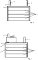
- FIG. 3 A water-air heat exchanger is shown, which has a collecting box 16 and heat exchanger tubes 17, with water for heating (or cooling) a gas (in particular air) flowing past the heat exchanger tubes 17 being provided through both the collecting container 16 and the heat exchanger tubes 17. There is an electrical heating coating 13 on the collecting box 16.
- a plurality of heat exchanger tubes 17 are connected to the collecting box 16 via connection pieces 18. At least 3, or at least 5, or at least 20 heat exchanger tubes 17 can be connected to the same collecting box 16.
- the water can enter via an inlet (inlet pipe 11) and exit via an outlet (outlet pipe 12).
Description
Die Erfindung betrifft einen Wärmetauscher, insbesondere einen Wasser-Luft-Wärmetauscher oder einen Öl-Wasser-Wärmetauscher nach Anspruch 1 sowie ein Verfahren zur Herstellung eines Wärmetauschers, insbesondere eines Wasser-Luft-Wärmetauschers oder eines Öl-Wasser-Wärmetauschers nach Anspruch 6.The invention relates to a heat exchanger, in particular a water-air heat exchanger or an oil-water heat exchanger according to claim 1, and a method for producing a heat exchanger, in particular a water-air heat exchanger or an oil-water heat exchanger according to claim 6.
Beispielsweise
Ein weiterer Öl-Wasser-Wärmetauscher ist in
In einer besonderen Ausführungsform wird dort ein elektrischer Heizer in einem Innenraum des Wärmetauschers vorgeschlagen, um eines der miteinander wechselwirkenden Fluide des Wärmetauschers zu erwärmen.In a particular embodiment, an electric heater is proposed there in an interior space of the heat exchanger in order to heat one of the interacting fluids of the heat exchanger.
Grundsätzlich wird es bei den bekannten Öl-Wasser-Wärmetauschern als nachteilig empfunden, dass bei diesen entweder gar nicht oder nur vergleichsweise aufwändig und ineffektiv ein Vorheizen erfolgen kann. Insbesondere wird die Reduktion von Schadstoffen, die entstehen, wenn das Motoröl nicht auf Betriebstemperatur ist, als verbesserungswürdig angesehen.In principle, it is felt to be disadvantageous in the known oil-water heat exchangers that they can either not be preheated at all or can only be preheated in a comparatively complex and ineffective manner. In particular, the reduction of pollutants that arise when the engine oil is not at operating temperature is seen as in need of improvement.
Weiterhin sei hinsichtlich des Standes der Technik grundsätzlich auf
Weiterhin sei hinsichtlich des Standes der Technik auf
Es ist Aufgabe der Erfindung, einen Wärmetauscher vorzuschlagen, der auf einfache Weise und effektiv eine Erwärmung eines de Wärmetauscher durchströmenden Fluids ermöglicht.Furthermore, regarding the state of the art, please refer to
It is the object of the invention to propose a heat exchanger which enables a fluid flowing through the heat exchanger to be heated in a simple and effective manner.
Diese Aufgabe wird durch die Merkmale des Anspruches 1 gelöst.This object is achieved by the features of claim 1.
Insbesondere wird die Aufgabe durch einen Wärmetauscher, insbesondere Wasser-Luft-Wärmetauscher oder Öl-Wasser-Wärmetauscher, gelöst, umfassend mindestens einen ersten Fluidkanal zum Führen eines ersten Fluids (z.B. Öl eines Öl-Wasser-Wärmetauschers oder Wasser eines Wasser-Luft-Wärmetauschers), sowie mindestens einen zweiten Fluidkanal zum Führen eines zweiten Fluids (z.B. Wasser des Öl-Wasser-Wärmetauschers oder Luft des Wasser-Luft-Wärmetauschers), wobei der mindestens eine erste Fluidkanal an ein Fluidaufnahmevolumen (insbesondere Auslassseite) angeschlossen ist, wobei das Fluidaufnahmevolumen mit einer elektrischen Heizbeschichtung ausgestattet ist, wobei das Fluidaufnahmevolumen durch ein separates Modul bereitgestellt wird, wobei das separate Modul an die übrigen Bestandteile des Wärmetauschers befestigbar ist oder befestigt ist. Der Wärmetauscher kann im Allgemeinen ein Flüssigkeit-Flüssigkeit-Wärmetauscher oder Flüssigkeit-Gas-Wärmetauscher oder Gas-Gas-Wärmetauscher sein.In particular, the object is achieved by a heat exchanger, in particular water-air heat exchanger or oil-water heat exchanger, comprising at least one first fluid channel for guiding a first fluid (e.g. oil from an oil-water heat exchanger or water from a water-air heat exchanger ), as well as at least one second fluid channel for guiding a second fluid (e.g. water of the oil-water heat exchanger or air of the water-air heat exchanger), the at least one first fluid channel being connected to a fluid receiving volume (in particular the outlet side), the fluid receiving volume is equipped with an electrical heating coating, wherein the fluid receiving volume is provided by a separate module, wherein the separate module can be or is attached to the remaining components of the heat exchanger. The heat exchanger can generally be a liquid-liquid heat exchanger or a liquid-gas heat exchanger or a gas-gas heat exchanger.
Ein Kerngedanke der Erfindung liegt darin, die an sich beispielsweise aus
In einer konkreten Ausführungsform wird das Fluidaufnahmevolumen durch einen Fluidaufnahmebehälter, insbesondere Ölaufnahmebehälter, definiert. Ein derartiger Fluidaufnahmebehälter, insbesondere Ölaufnahmebehälter, ist vorzugsweise auslassseitig an einen oder mehrere Fluidkanäle angeschlossen, durch die vorzugsweise Öl strömt. Dadurch kann auf effektive Art und Weise eine zusätzliche Erwärmung (beispielsweise nach dem Motorstart eines Kraftfahrzeuges) erfolgen.In a specific embodiment, the fluid receiving volume is defined by a fluid receiving container, in particular an oil receiving container. Such a fluid receiving container, in particular an oil receiving container, is preferably connected on the outlet side to one or more fluid channels through which oil preferably flows. As a result, additional heating can take place in an effective manner (for example after the engine of a motor vehicle has been started).
In einer konkreten Ausführungsform kann das Fluidaufnahmevolumen durch ein Anschlussrohr, insbesondere Auslassrohr, vorzugsweise eines Öl-Wasser-Wärmetauschers, definiert sein. Dadurch wird auf einfache Art und Weise (unter Ausnutzung bestehender Strukturen) eine Zuerwärmung des Fluids, insbesondere Öls, ermöglicht.In a specific embodiment, the fluid receiving volume can be defined by a connection pipe, in particular an outlet pipe, preferably an oil-water heat exchanger. This is a simple way (under Use of existing structures) allows the fluid, in particular oil, to be heated up.
In einer Ausführungsform kann ein Turbulator vorgesehen sein. Dieser ist vorzugsweise in der Nähe einer elektrischen Heizbeschichtung (also insbesondere nicht weiter als 5 cm, insbesondere 2 cm entfernt) vorgesehen. Beispielsweise kann der Turbulator innerhalb des (mit einer elektrischen Heizbeschichtung versehenen) Auslassrohres angeordnet sein.In one embodiment, a turbulator can be provided. This is preferably provided in the vicinity of an electrical heating coating (ie in particular not further than 5 cm, in particular 2 cm away). For example, the turbulator can be arranged inside the outlet pipe (provided with an electrical heating coating).
Grundsätzlich kann die elektrische Heizbeschichtung an einer Außenwand des Fluidaufnahmevolumens (beispielsweise Auslassrohres) oder an einer Innenwand des Fluidaufnahmevolumens (beispielsweise Auslassrohres) angeordnet sein. Wenn ein Turbulator vorgesehen ist, kann dieser ggf. auch selbst mit einer elektrischen Heizbeschichtung versehen sein.In principle, the electrical heating coating can be arranged on an outer wall of the fluid receiving volume (for example outlet pipe) or on an inner wall of the fluid receiving volume (for example outlet pipe). If a turbulator is provided, it can optionally also be provided with an electrical heating coating itself.
Das Fluidaufnahmevolumen wird durch ein separates Modul bereitgestellt, wobei das separate Modul an die übrigen Bestandteile des Wärmetauschers befestigbar ist oder befestigt ist. Erfindungsgemäß wird also ein separates Fluidaufnahmevolumen vorgeschlagen, so dass bestehende Wärmetauscher (insbesondere Öl-Wasser-Wärmetauscher) durch eine einfache Aufrüstung weiter verbessert werden können. Andererseits hat die modulartige Ausbildung des Fluidaufnahmevolumens auch den Vorteil, dass Herstellungskosten ggf. reduziert werden können, beispielsweise dadurch, dass dasselbe Fluidaufnahmemodul für verschiedene Wärmetauschertypen und/oder -großen eingesetzt wird.The fluid receiving volume is provided by a separate module, the separate module being attachable or being attached to the other components of the heat exchanger. According to the invention, a separate fluid receiving volume is proposed so that existing heat exchangers (in particular oil-water heat exchangers) can be further improved by a simple upgrade. On the other hand, the modular design of the fluid intake volume also has the advantage that manufacturing costs can possibly be reduced, for example by using the same fluid intake module for different types and / or sizes of heat exchangers.
Besonders bevorzugt ist die Heizbeschichtung zum Betrieb im Niedervoltbereich, vorzugsweise für 12 Volt, 24 Volt oder 48 Volt ausgelegt. Entsprechende elektrische und/oder elektronische Komponenten des Öl-Wasser-Wärmetauschers sind dann vorzugsweise ebenfalls für einen solchen Niedervoltbereich (12 Volt, 24 Volt oder 48 Volt) ausgelegt. Insbesondere bei einer Anwendung im Niedervoltbereich kann auf synergistische Art und Weise eine effektive Vorheizung mit einfachen Mitteln realisiert werden. Unter "Niedervoltbereich" soll vorzugsweise eine Betriebsspannung von unter 100 V, insbesondere unter 60 V (Gleichstrom) verstanden werden.The heating coating is particularly preferably designed for operation in the low-voltage range, preferably for 12 volts, 24 volts or 48 volts. Appropriate electrical and / or electronic components of the oil-water heat exchanger are then preferably also designed for such a low-voltage range (12 volts, 24 volts or 48 volts). Particularly when used in the low-voltage range, effective preheating can be achieved with simple means in a synergistic manner. "Low-voltage range" should preferably be understood to mean an operating voltage of less than 100 V, in particular less than 60 V (direct current).
In einer Ausführungsform ist die Heizbeschichtung mittelbar, insbesondere über eine Isolationsschicht vermittelt, auf dem oder in dem Fluidaufnahmevolumen aufgebracht. Eine derartige Isolationsschicht kann beispielsweise durch eine Haftvermittlerschicht gebildet werden oder über eine solche auf dem Öl-Wasser-Wärmetauscher angebracht sein. Bevorzugt kann für die Isolationsschicht ein Polymermaterial oder ein keramisches Material (z.B. Al2O3) verwendet werden. Vorzugsweise wird die Isolierschicht jedoch durch eine Passivierung, insbesondere ein Oxidieren, insbesondere Eloxieren (von Aluminium oder einer Aluminiumlegierung), vorzugsweise einer Oberfläche, beispielsweise einer Außen- und/oder Innenfläche, des Fluidaufnahmevolumens, bereitgestellt. Insgesamt wird (gerade in Niedervolt-Anwendungen) eine einfache und dennoch ausreichende elektrische Isolierung bereitgestellt. Alternativ kann die Heizbeschichtung sogar unmittelbar auf dem oder in dem Fluidaufnahmevolumen aufgebracht sein (beispielsweise in Niedervolt-Anwendungen und/oder wenn der Untergrund nicht oder nur schlecht elektrisch leitend ist). Die Heizbeschichtung und/oder Isolationsschicht ist vorzugsweise (voll-)flächig auf dem Fluidaufnahmevolumen aufgebracht. Weiterhin kann die Heizbeschichtung und/oder die Isolationsschicht eine (zumindest im Wesentlichen) konstante Schichtdicke aufweisen. Die Heizbeschichtung und/oder die Isolationsschicht kann/können per se forminstabil (bzw. nicht-selbsttragend) ausgebildet sein. Auf ein Substrat kann verzichtet werden, so dass die Heizbeschichtung (und eine optionale Isolationsschicht) ggf. frei von einem Substrat ausgebildet ist. Ein ggf. notwendige Trage- und/oder Stützstruktur kann durch das Fluidaufnahmevolumen (bzw. ein Wandung desselben) bereitgestellt werden. Grundsätzlich kann die Heizbeschichtung stoffschlüssig mit einer Oberfläche, insbesondere Außen- und/oder Innenfläche des Fluidaufnahmevolumens verbunden sein.In one embodiment, the heating coating is applied indirectly, in particular via an insulation layer, to or in the fluid receiving volume. Such an insulation layer can be formed, for example, by an adhesion promoter layer or attached to the oil-water heat exchanger via such a layer. A polymer material or a ceramic material (for example Al 2 O 3 ) can preferably be used for the insulation layer. Preferably, however, the insulating layer is provided by passivation, in particular oxidizing, in particular anodizing (of aluminum or an aluminum alloy), preferably a surface, for example an outer and / or inner surface, of the fluid receiving volume. Overall, simple yet adequate electrical insulation is provided (especially in low-voltage applications). Alternatively, the heating coating can even be applied directly to or in the fluid receiving volume (for example in low-voltage applications and / or if the substrate is not or only poorly electrically conductive). The heating coating and / or insulation layer is preferably applied over the entire surface of the fluid receiving volume. Furthermore, the heating coating and / or the insulation layer can have an (at least essentially) constant layer thickness. The heating coating and / or the insulation layer can per se be designed to be dimensionally unstable (or not self-supporting). A substrate can be dispensed with, so that the heating coating (and an optional insulation layer) may be formed free of a substrate. A possibly necessary carrying and / or support structure can be provided by the fluid receiving volume (or a wall of the same). In principle, the heating coating can be materially connected to a surface, in particular an outer and / or inner surface, of the fluid receiving volume.
In einer alternativen Ausführungsform ist die Heizbeschichtung als durchgehende (insbesondere unstrukturierte und/oder ununterbrochene) Schicht ausgebildet.In an alternative embodiment, the heating coating is designed as a continuous (in particular unstructured and / or uninterrupted) layer.
Die Heizbeschichtung kann im Allgemeinen mindestens einen Abschnitt aufweisen, innerhalb dessen in zwei aufeinander senkrechten Richtungen über einen Weg von mindestens 1 cm, vorzugsweise mindesten 2 cm, noch weiter vorzugsweise mindestens 4 cm keine Unterbrechungen in der Heizbeschichtung vorliegen. Beispielsweise kann die Heizbeschichtung mindestens einen rechteckförmigen Abschnitt mit einer Länge und einer Breite von je mindestens 1 cm, vorzugsweise mindesten 2 cm, noch weiter vorzugsweise mindestens 4 cm umfassen, innerhalb dessen keine Unterbrechungen oder ggf. sonstigen Strukturen in der Heizbeschichtung vorliegen. Unter einer "Unterbrechung" innerhalb der Heizbeschichtung ist ein Abschnitt zu verstehen, durch den kein Strom fließen kann, beispielsweise da dieser Abschnitt (gänzlich) frei von Material bleibt und/oder (zumindest teilweise) durch einen Isolator ausgefüllt ist. Die Heizbeschichtung kann (thermisch) aufgespritzt werden (unabhängig davon, ob sie unstrukturiert oder strukturiert ist, im Endzustand). In diesem Zusammenhang hat es sich überraschend gezeigt, dass selbst eine derartig einfach ausgebildete Heizbeschichtung eine ausreichende Erwärmung des Öls bewirken kann.The heating coating can generally have at least one section within which there are no interruptions in the heating coating in two mutually perpendicular directions over a distance of at least 1 cm, preferably at least 2 cm, even more preferably at least 4 cm. For example, the heating coating can comprise at least one rectangular section with a length and a width of at least 1 cm, preferably at least 2 cm, even more preferably at least 4 cm, within which there are no interruptions or possibly other structures in the heating coating. An “interruption” within the heating coating is to be understood as a section through which no current can flow, for example because this section remains (completely) free of material and / or is (at least partially) filled with an insulator. The heating coating can be (thermally) sprayed on (regardless of whether it is unstructured or structured, in the final state). In this context it has surprisingly been found that even such a simply configured heating coating can bring about sufficient heating of the oil.
In einer weiteren alternativen Ausführungsform ist die Heizbeschichtung als strukturierte Schicht ausgebildet. Die Heizbeschichtung wird dabei vorzugsweise durch ein Maskierverfahren (vorzugsweise unter Verwendung von Silikon, das geprägt werden kann) strukturiert. Derartige bekannte Maskierverfahren, erlauben eine zufriedenstellende Strukturierung und sind weniger aufwändig als beispielsweise Laserverfahren zur Strukturierung, die gerade im Hochvoltbereich eingesetzt werden. Insgesamt werden daher auf synergistische Art und Weise die Vorteile eines Maskierverfahrens im Hinblick auf die vorliegende Heizbeschichtung ausgenutzt.In a further alternative embodiment, the heating coating is designed as a structured layer. The heating coating is preferably structured by a masking process (preferably using silicone, which can be embossed). Such known masking methods allow a satisfactory structuring and are less complex than, for example, laser methods for structuring, which are used in the high-voltage range. Overall, therefore, the advantages of a masking process are used in a synergistic manner with regard to the present heating coating.
Die oben beschriebene Isolierschicht kann eine Dicke von mindestens 50 µm, vorzugsweise mindestens 200 µm und/oder höchstens 1000 µm, vorzugsweise höchstens 500 µm betragen.The insulating layer described above can have a thickness of at least 50 μm, preferably at least 200 μm and / or at most 1000 μm, preferably at most 500 μm.
Die Heizbeschichtung hat vorzugsweise eine Höhe (Dicke) von mindestens 5 µm, vorzugsweise mindestens 10 µm und/oder höchstens einem 1 mm, vorzugsweise höchstens 500 µm, noch weiter vorzugsweise höchstens 30 µm, noch weiter vorzugsweise höchstens 20 µm. Eine durch die Heizbeschichtung definierte Leiterbahn kann mindestens 1 mm, vorzugsweise mindestens 3 mm, noch weiter vorzugsweise mindestens 5 mm, noch weiter vorzugsweise mindestens 10 mm, noch weiter vorzugsweise mindestens 30 mm breit sein. Unter "Breite" soll die Ausdehnung der Leiterbahn senkrecht zu ihrer Längserstreckung (die üblicherweise auch die Richtung des Stromflusses definiert) verstanden werden.The heating coating preferably has a height (thickness) of at least 5 μm, preferably at least 10 μm and / or at most 1 mm, preferably at most 500 μm, even more preferably at most 30 μm, even more preferably at most 20 μm. A conductor path defined by the heating coating can be at least 1 mm, preferably at least 3 mm, even more preferably at least 5 mm, even more preferably at least 10 mm, more preferably at least 30 mm wide. “Width” should be understood to mean the extension of the conductor track perpendicular to its longitudinal extension (which usually also defines the direction of the current flow).
In einer alternativen Ausführungsform ist über der Heizbeschichtung eine Schutzabdeckung, beispielsweise eine Silikon-Schutzschicht, angebracht. Alternativ kann jedoch auch (in einer besonders einfach herstellbaren Ausführungsform) die Heizbeschichtung eine Außenseite oder Innenseite des Fluidaufnahmevolumens definieren.In an alternative embodiment, a protective cover, for example a silicone protective layer, is attached over the heating coating. Alternatively, however, the heating coating can also define an outside or inside of the fluid receiving volume (in an embodiment that is particularly easy to manufacture).
In einer konkreten Ausführungsform weist der Öl-Wasser-Wärmetauscher mehrere Module, insbesondere Wannenelemente auf, die weiter vorzugsweise, wie in
Die Aufgabe wird weiterhin gelöst durch ein Verfahren zur Herstellung eines Wärmetauschers, insbesondere eines Wasser-Luft-Wärmetauschers oder eines Öl-Wasser-Wärmetauschers, insbesondere der oben beschriebenen Art, gemäß Anspruch 6, umfassend das Bereitstellen mindestens eines ersten Fluidkanals zum Führen eines ersten Fluids (z.B. eines Öls des Öl-Wasser-Wärmetauschers oder Wasser des Wasser-Luft-Wärmetauschers) sowie mindestens eines zweiten Fluidkanals zum Führen eines zweiten Fluids (z.B. Wasser des Öl-Wasser-Wärmetauschers oder Luft des Wasser-Luft-Wärmetauschers), wobei der mindestens eine erste Fluidkanal an ein Fluidaufnahmevolumen, insbesondere auslassseitig, angeschlossen wird, wobei das Fluidaufnahmevolumen mit einer elektrischen Heizbeschichtung ausgestattet wird (bzw. eine Oberfläche des Fluidaufnahmevolumen unmittelbar oder mittelbar mit der elektrischen Heizbeschichtung beschichtet wird). Zwischen den beiden genannten Schritten kann das Aufbringen einer Isolierschicht auf eine Oberfläche des Fluidaufnahmevolumens durchgeführt werden (bzw. eine Oberfläche des Fluidaufnahmevolumens unmittelbar oder mittelbar mit der Isolierschicht beschichtet werden), beispielsweise durch eine Passivierung (Oxidierung, insbesondere Eloxierung) eines Untergrundes, beispielsweise eines Wärmetauschergehäuses. Die elektrische Heizbeschichtung kann ggf. (thermisch) aufgespritzt werden. Insofern weiter oben (im Zusammenhang mit dem Wärmetauscher) Merkmale beschrieben sind, die zumindest auch mit der Herstellung des Öl-Wasser-Wärmetauschers in Zusammenhang stehen, werden diese Verfahrensmerkmale auch als bevorzugte Ausführungsformen des Verfahrens vorgeschlagen.The object is also achieved by a method for producing a heat exchanger, in particular a water-air heat exchanger or an oil-water heat exchanger, in particular of the type described above, according to claim 6, comprising the provision of at least one first fluid channel for guiding a first fluid (e.g. an oil of the oil-water heat exchanger or water of the water-air heat exchanger) and at least one second fluid channel for guiding a second fluid (e.g. water of the oil-water heat exchanger or air of the water-air heat exchanger), the at least one first fluid channel is connected to a fluid receiving volume, in particular on the outlet side, the fluid receiving volume being equipped with an electrical heating coating (or a surface of the fluid receiving volume being coated directly or indirectly with the electrical heating coating). Between the two mentioned steps, the application of an insulating layer to a surface of the fluid receiving volume can be carried out (or a surface of the fluid receiving volume can be coated directly or indirectly with the insulating layer), for example by passivation (oxidation, in particular anodizing) of a substrate, for example a heat exchanger housing. If necessary, the electrical heating coating can be sprayed on (thermally). Insofar as features are described further above (in connection with the heat exchanger) which are at least also related to the production of the oil-water heat exchanger, these method features are also proposed as preferred embodiments of the method.
Die obengenannte Aufgabe wird weiterhin durch die Verwendung eines Wärmetauschers der oben beschrieben Art oder hergestellt nach der oben beschriebenen Art, als Wasser-Luft-Wärmetauscher oder als Öl-Wasser-Wärmetauscher, insbesondere für den Verbrennungsmotor eines Kraftfahrzeuges, gelöst.The above-mentioned object is also achieved by using a heat exchanger of the type described above or produced according to the type described above, as a water-air heat exchanger or as an oil-water heat exchanger, in particular for the internal combustion engine of a motor vehicle.
Weitere Ausführungsformen ergeben sich aus den Unteransprüchen.Further embodiments emerge from the subclaims.
Im Allgemeinen kann die Isolierschicht ein Keramikmaterial oder ein Polymermaterial sein oder aus einem solchen Material bestehen, wobei als Keramikmaterial beispielsweise Al2O3 in Frage kommt.In general, the insulating layer can be a ceramic material or a polymer material or consist of such a material, Al 2 O 3, for example, being considered as the ceramic material.
Die Heizschicht kann beispielsweise in einem Plasmabeschichtungsverfahren, insbesondere Plasmaspritzen, oder in einem Siebdruckverfahren oder als Widerstandspaste, insbesondere auf die Isolierschicht, aufgetragen werden. In dem Plasmabeschichtungsverfahren kann beispielsweise zunächst eine elektrisch leitende Schicht, insbesondere auf die Isolierschicht, aufgetragen werden. Aus der elektrisch leitfähigen Schicht können anschließend Bereiche ausgeschnitten werden, so dass eine Leiterbahn oder mehrere Leiterbahnen übrigbleiben. Bevorzugt kommt jedoch eine Maskiertechnik zum Einsatz. Die Leiterbahnen können dann den Heizwiderstand oder mehrere Heizwiderstände bilden. Die genannten Bereiche können alternativ zu einer Maskiertechnik, beispielsweise mittels eines Lasers aus der leitfähigen Schicht herausgeschnitten werden. Die Heizbeschichtung kann beispielsweise eine Metallschicht sein und ggf. Nickel und/oder Chrom enthalten oder aus diesen Materialien bestehen. Beispielsweise können 70-90% Nickel und 10-30% Chrom verwendet werden, wobei ein Verhältnis von 80% Nickel und 20% Chrom als gut geeignet betrachtet wird.The heating layer can be applied, for example, in a plasma coating process, in particular plasma spraying, or in a screen printing process, or as a resistance paste, in particular on the insulating layer. In the plasma coating process, for example, an electrically conductive layer can first be applied, in particular to the insulating layer. Areas can then be cut out of the electrically conductive layer so that one or more conductor tracks remain. However, a masking technique is preferably used. The conductor tracks can then form the heating resistor or several heating resistors. As an alternative to a masking technique, the areas mentioned can be cut out of the conductive layer, for example by means of a laser. The heating coating can for example be a metal layer and possibly contain nickel and / or chromium or consist of these materials. For example 70-90% nickel and 10-30% chromium can be used, with a ratio of 80% nickel and 20% chromium being considered to be suitable.
Die Heizbeschichtung kann beispielsweise eine Fläche von mindestens 5 cm2, vorzugsweise mindestens 10 cm2 und/oder höchstens 200 cm2, vorzugsweise höchstens 100 cm2, einnehmen. Der Öl-Wasser-Wärmetauscher kann ein Gesamtvolumen von vorzugsweise mindestens 200 cm3, noch weiter vorzugsweise mindestens 500 cm3, noch weiter vorzugsweise mindestens 800 cm3 und/oder höchstens 5000 cm3, vorzugsweise höchstens 2000 cm3, aufweisen. Beispielsweise kann der Öl-Wasser-Wärmetauscher 15-25 cm lang und/oder 8-12 cm breit und/oder 3-7 cm hoch (dick) sein.The heating coating can, for example, occupy an area of at least 5 cm 2 , preferably at least 10 cm 2 and / or at most 200 cm 2 , preferably at most 100 cm 2 . The oil-water heat exchanger can have a total volume of preferably at least 200 cm 3 , even more preferably at least 500 cm 3 , even more preferably at least 800 cm 3 and / or at most 5000 cm 3 , preferably at most 2000 cm 3 . For example, the oil-water heat exchanger can be 15-25 cm long and / or 8-12 cm wide and / or 3-7 cm high (thick).
Der Öl-Wasser-Wärmetauscher weist vorzugsweise einen oder mehrere erste Fluidkanäle zum Führen des Öls und einen oder mehrere zweite Fluidkanäle zum Führen des Wassers auf.The oil-water heat exchanger preferably has one or more first fluid channels for guiding the oil and one or more second fluid channels for guiding the water.
Für eine Steuerung, insbesondere Regelung, der elektrischen Heizbeschichtung kann ein Bi-Metall-Schalter, evtl. mit zwei redundanten Schaltereinrichtungen, vorgesehen sein.A bimetal switch, possibly with two redundant switch devices, can be provided for controlling, in particular regulating, the electrical heating coating.
Nur die Ausführungsformen, die in den Bereich der Ansprüche fallen, gelten als Ausführungsformen der Erfindung. Alle anderen Ausführungsformen werden lediglich als Beispiele betrachtet, die für das Verständnis der Erfindung nützlich sind.Only those embodiments that fall within the scope of the claims are considered to be embodiments of the invention. All other embodiments are considered to be examples that are useful for understanding the invention.
Nachfolgend wird die Erfindung anhand von Ausführungsbeispielen beschrieben, die anhand der Abbildungen näher erläutert werden. Hierbei zeigen:
- Fig. 1
- eine schematische Seitenansicht eines Öl-Wasser-Wärmetauschers gemäß einer ersten Ausführungsform der Erfindung;
- Fig. 2
- einen Öl-Wasser-Wärmetauscher gemäß einer alternativen Ausführungsform der Erfindung; und
- Fig. 3
- einen Wasser-Luft-Wärmetauscher gemäß einer Ausführungsform der Erfindung.
- Fig. 1
- a schematic side view of an oil-water heat exchanger according to a first embodiment of the invention;
- Fig. 2
- an oil-water heat exchanger according to an alternative embodiment of the invention; and
- Fig. 3
- a water-air heat exchanger according to an embodiment of the invention.
In der nachfolgenden Beschreibung werden für gleiche und gleichwirkende Teile dieselben Bezugsziffern verwendet.In the following description, the same reference numbers are used for parts that are the same and have the same effect.
In der alternativen Ausführungsform gemäß
In
- 1010
- WannenelementTub element
- 1111
- EinlassrohrInlet pipe
- 1212th
- AuslassrohrOutlet pipe
- 1313th
- elektrische Heizbeschichtungelectrical heating coating
- 1414th
- FluidaufnahmebehälterFluid holding container
- 1515th
- Fluidaufnahmebehälter-AuslassrohrFluid receiver outlet tube
- 1616
- SammelkastenCollection box
- 1717th
- WärmetauscherrohrHeat exchanger tube
- 1818th
- AnschlusseinrichtungConnection device
- 1919th
- Deckelcover
- 2020th
- AuslassOutlet
- 2121
- Wärmetauscher-HauptkörperHeat exchanger main body
Claims (7)
- Heat exchanger, in particular water-air heat exchanger or oil-water heat exchanger, comprising at least one first fluid channel for conducting a first fluid, and at least one second fluid channel for conducting a second fluid,
wherein the at least one first fluid channel is connected to a fluid-receiving volume, in particular at an outlet side, wherein the fluid-receiving volume is equipped with an electric heating coating (13),
characterized in that
the fluid-receiving volume is provided by a separate module, wherein the separate module is fastenable or fastened to the other constituent parts of the heat exchanger. - Heat exchanger according to Claim 1,
characterized in that
the fluid-receiving volume is defined by a fluid-receiving vessel (14), in particular oil-receiving vessel. - Heat exchanger according to Claim 1 or 2, characterized in that
the fluid-receiving volume is defined by a connection pipe, in particular outlet pipe (12). - Heat exchanger according to any of the preceding claims,
characterized in that
a turbulator is provided preferably in the vicinity of an electric heating coating (13). - Heat exchanger according to any of the preceding claims,
characterized in that
the electric heating coating (13) is designed for operation in the low-voltage range, preferably for 12 volts, 24 volts or 48 volts. - Method for producing a heat exchanger, in particular a water-air heat exchanger or an oil-water heat exchanger, comprising the steps:- providing at least one first fluid channel for conducting a first fluid, and a second fluid channel for conducting a second fluid, wherein the at least one first fluid channel is connected to a fluid-receiving volume, in particular at an outlet side, wherein the fluid-receiving volume is equipped with an electric heating coating (13), wherein the fluid-receiving volume is provided by a separate module, wherein the separate module is fastenable or fastened to the other constituent parts of the heat exchanger.
- Use of a heat exchanger according to any of Claims 1 to 5, preferably produced according to Claim 6, as a water-air heat exchanger or as an oil-water heat exchanger, in particular for the internal combustion engine of a motor vehicle.
Applications Claiming Priority (2)
| Application Number | Priority Date | Filing Date | Title |
|---|---|---|---|
| DE102016102895.9A DE102016102895A1 (en) | 2016-02-18 | 2016-02-18 | Heat exchanger, in particular water-air heat exchanger or oil-water heat exchanger |
| PCT/EP2017/053280 WO2017140668A1 (en) | 2016-02-18 | 2017-02-14 | Heat exchanger, in particular water-air-heat exchanger or oil-water-heat exchanger |
Publications (2)
| Publication Number | Publication Date |
|---|---|
| EP3417227A1 EP3417227A1 (en) | 2018-12-26 |
| EP3417227B1 true EP3417227B1 (en) | 2021-06-23 |
Family
ID=58191391
Family Applications (1)
| Application Number | Title | Priority Date | Filing Date |
|---|---|---|---|
| EP17707776.5A Active EP3417227B1 (en) | 2016-02-18 | 2017-02-14 | Heat exchanger, in particular water-air heat exchanger or oil-water heat exchanger |
Country Status (7)
| Country | Link |
|---|---|
| US (1) | US11384943B2 (en) |
| EP (1) | EP3417227B1 (en) |
| JP (2) | JP2019507277A (en) |
| KR (1) | KR20180112836A (en) |
| CN (1) | CN108700383A (en) |
| DE (1) | DE102016102895A1 (en) |
| WO (1) | WO2017140668A1 (en) |
Families Citing this family (3)
| Publication number | Priority date | Publication date | Assignee | Title |
|---|---|---|---|---|
| CN109812864A (en) * | 2018-11-14 | 2019-05-28 | 赵荣军 | A kind of diversity type Natural Circulation heater |
| DE102019213319A1 (en) * | 2019-09-03 | 2021-03-04 | Mahle International Gmbh | Heat exchanger |
| FR3102550A1 (en) * | 2019-10-29 | 2021-04-30 | Valeo Systemes Thermiques | Plate heat exchanger comprising an electric heating element |
Family Cites Families (23)
| Publication number | Priority date | Publication date | Assignee | Title |
|---|---|---|---|---|
| JPH01150096A (en) * | 1987-12-04 | 1989-06-13 | Hitachi Metals Ltd | Conduit having heat-insulating function |
| JP3015829B2 (en) | 1992-10-02 | 2000-03-06 | 株式会社小野測器 | Engine lubricating oil temperature control device |
| JP3855507B2 (en) * | 1998-12-16 | 2006-12-13 | 株式会社デンソー | Heat exchanger for heating |
| US6178292B1 (en) | 1997-02-06 | 2001-01-23 | Denso Corporation | Core unit of heat exchanger having electric heater |
| JP2002283835A (en) | 2001-03-27 | 2002-10-03 | Calsonic Kansei Corp | Heater for heating and heat exchanger for heating |
| DE10157399B4 (en) * | 2001-11-23 | 2008-04-10 | Webasto Ag | Radiator with two heat-supplying facilities |
| JP4280545B2 (en) | 2003-05-14 | 2009-06-17 | カルソニックカンセイ株式会社 | Combined heat exchanger |
| JP2004352057A (en) | 2003-05-28 | 2004-12-16 | Denso Corp | Air conditioner for vehicle |
| KR101230694B1 (en) * | 2003-12-22 | 2013-02-07 | 엔테그리스, 아이엔씨. | Exchange devices with potted hollow conduits |
| KR101138668B1 (en) * | 2005-01-12 | 2012-07-02 | 한라공조주식회사 | Heat exchanger |
| JP2010113803A (en) | 2007-02-14 | 2010-05-20 | Nasakoa Kk | Heating method using conductive ceramic layer and engine |
| US8752615B2 (en) * | 2008-01-08 | 2014-06-17 | General Electric Company | Methods and systems for controlling temperature in a vessel |
| BRPI1008160A2 (en) * | 2009-05-28 | 2016-03-08 | Gmz Energy Inc | apparatus, solar electric generator and method |
| DE102010031468A1 (en) * | 2010-07-16 | 2012-01-19 | Behr Gmbh & Co. Kg | Fluid channel for a heat exchanger |
| FR2966580B1 (en) * | 2010-10-20 | 2014-01-03 | Valeo Systemes Thermiques | HEAT EXCHANGER AND CORRESPONDING VENTILATION AND HEATING INSTALLATION |
| DE102010063141A1 (en) | 2010-12-15 | 2012-06-21 | Mahle International Gmbh | heat exchangers |
| DE102011003296A1 (en) | 2011-01-28 | 2012-08-02 | Behr Gmbh & Co. Kg | Heat exchanger |
| DE102011006248A1 (en) | 2011-03-28 | 2012-10-04 | BSH Bosch und Siemens Hausgeräte GmbH | Refrigeration device with a heater |
| DE102011081831A1 (en) | 2011-08-30 | 2013-02-28 | Webasto Ag | Electric heating unit, heating apparatus for a vehicle and method of manufacturing a heating unit |
| DE102012209936A1 (en) | 2012-06-13 | 2013-12-19 | Webasto Ag | Electric heating device for a motor vehicle |
| DE102013010907A1 (en) | 2013-06-28 | 2014-12-31 | Webasto SE | An electric heater and a method of manufacturing an electric heater |
| US20150093523A1 (en) * | 2013-09-30 | 2015-04-02 | Kyle Ryan Kissell | Heatable coating with nanomaterials |
| DE112014005907T5 (en) | 2013-12-19 | 2016-09-08 | Dana Canada Corporation | Conical heat exchanger |
-
2016
- 2016-02-18 DE DE102016102895.9A patent/DE102016102895A1/en not_active Withdrawn
-
2017
- 2017-02-14 JP JP2018542164A patent/JP2019507277A/en active Pending
- 2017-02-14 US US15/999,656 patent/US11384943B2/en active Active
- 2017-02-14 KR KR1020187026348A patent/KR20180112836A/en not_active IP Right Cessation
- 2017-02-14 WO PCT/EP2017/053280 patent/WO2017140668A1/en active Application Filing
- 2017-02-14 CN CN201780011980.7A patent/CN108700383A/en active Pending
- 2017-02-14 EP EP17707776.5A patent/EP3417227B1/en active Active
-
2021
- 2021-02-25 JP JP2021028137A patent/JP7032683B2/en active Active
Non-Patent Citations (1)
| Title |
|---|
| None * |
Also Published As
| Publication number | Publication date |
|---|---|
| JP2019507277A (en) | 2019-03-14 |
| KR20180112836A (en) | 2018-10-12 |
| WO2017140668A1 (en) | 2017-08-24 |
| US11384943B2 (en) | 2022-07-12 |
| CN108700383A (en) | 2018-10-23 |
| JP7032683B2 (en) | 2022-03-09 |
| DE102016102895A1 (en) | 2017-08-24 |
| US20210207816A1 (en) | 2021-07-08 |
| JP2021101143A (en) | 2021-07-08 |
| EP3417227A1 (en) | 2018-12-26 |
Similar Documents
| Publication | Publication Date | Title |
|---|---|---|
| WO2013186106A1 (en) | Electrical heating system for a motor vehicle | |
| EP3417227B1 (en) | Heat exchanger, in particular water-air heat exchanger or oil-water heat exchanger | |
| EP2917555B1 (en) | Pre-heating device for a fuel injection system | |
| EP2376753A1 (en) | Device for producing electrical energy from exhaust gas | |
| EP1714810B1 (en) | Electric additional heater for an air conditioning system of a vehicle | |
| EP2398132A1 (en) | Pump power unit | |
| WO2019015861A1 (en) | Energy storage arrangement | |
| EP4032369A1 (en) | Printed circuit board and fluid heater | |
| EP3417210B1 (en) | Oil-water heat exchanger, in particular for the internal combustion engine of a motor vehicle | |
| EP3305017B1 (en) | Electrical heating means for mobile application | |
| DE2554650C3 (en) | Apparatus and method for cooling underground power cables | |
| EP3494294B1 (en) | Electrically heatable honeycomb body for exhaust gas treatment having a plurality of heating elements | |
| EP3417673B1 (en) | Heat exchanger system | |
| EP4277803A1 (en) | Multilayer braking resistance device for a vehicle | |
| EP2311571A2 (en) | Electrically heated spray nozzle | |
| WO2013163994A1 (en) | Liquid-cooled resistor | |
| DE102016118829A1 (en) | Electric heater for mobile applications | |
| EP3459110B1 (en) | Cooling box unit and power electronics device having a cooling box unit | |
| AT522500B1 (en) | Spiral heat exchanger | |
| EP3953646B1 (en) | Electric heating device | |
| DE102019128467A1 (en) | Electric heating devices, in particular for mobile applications | |
| EP2462334A1 (en) | Preheating device for preheating liquid and/or gaseous fuel for an internal combustion engine | |
| WO2017174478A1 (en) | Device for heating and/or shielding at least one wall | |
| CH617032A5 (en) | Cooling arrangement for tubular, heat-emitting electrical components | |
| DE102016214489A1 (en) | Metallic foil with applied planar electrical conductor and honeycomb body produced using the film |
Legal Events
| Date | Code | Title | Description |
|---|---|---|---|
| STAA | Information on the status of an ep patent application or granted ep patent |
Free format text: STATUS: UNKNOWN |
|
| STAA | Information on the status of an ep patent application or granted ep patent |
Free format text: STATUS: THE INTERNATIONAL PUBLICATION HAS BEEN MADE |
|
| PUAI | Public reference made under article 153(3) epc to a published international application that has entered the european phase |
Free format text: ORIGINAL CODE: 0009012 |
|
| STAA | Information on the status of an ep patent application or granted ep patent |
Free format text: STATUS: REQUEST FOR EXAMINATION WAS MADE |
|
| 17P | Request for examination filed |
Effective date: 20180807 |
|
| AK | Designated contracting states |
Kind code of ref document: A1 Designated state(s): AL AT BE BG CH CY CZ DE DK EE ES FI FR GB GR HR HU IE IS IT LI LT LU LV MC MK MT NL NO PL PT RO RS SE SI SK SM TR |
|
| AX | Request for extension of the european patent |
Extension state: BA ME |
|
| DAV | Request for validation of the european patent (deleted) | ||
| DAX | Request for extension of the european patent (deleted) | ||
| STAA | Information on the status of an ep patent application or granted ep patent |
Free format text: STATUS: EXAMINATION IS IN PROGRESS |
|
| 17Q | First examination report despatched |
Effective date: 20200417 |
|
| GRAP | Despatch of communication of intention to grant a patent |
Free format text: ORIGINAL CODE: EPIDOSNIGR1 |
|
| STAA | Information on the status of an ep patent application or granted ep patent |
Free format text: STATUS: GRANT OF PATENT IS INTENDED |
|
| RIC1 | Information provided on ipc code assigned before grant |
Ipc: F28D 21/00 20060101ALI20201208BHEP Ipc: F28D 9/00 20060101ALI20201208BHEP Ipc: F28D 1/053 20060101ALI20201208BHEP Ipc: F24D 13/04 20060101ALI20201208BHEP Ipc: F28F 13/00 20060101ALI20201208BHEP Ipc: F28D 7/00 20060101ALI20201208BHEP Ipc: H05B 3/12 20060101ALI20201208BHEP Ipc: F28F 13/18 20060101ALI20201208BHEP Ipc: F24H 9/18 20060101ALI20201208BHEP Ipc: F28F 9/02 20060101ALI20201208BHEP Ipc: F28D 1/00 20060101AFI20201208BHEP |
|
| INTG | Intention to grant announced |
Effective date: 20210104 |
|
| INTG | Intention to grant announced |
Effective date: 20210113 |
|
| GRAS | Grant fee paid |
Free format text: ORIGINAL CODE: EPIDOSNIGR3 |
|
| GRAA | (expected) grant |
Free format text: ORIGINAL CODE: 0009210 |
|
| STAA | Information on the status of an ep patent application or granted ep patent |
Free format text: STATUS: THE PATENT HAS BEEN GRANTED |
|
| AK | Designated contracting states |
Kind code of ref document: B1 Designated state(s): AL AT BE BG CH CY CZ DE DK EE ES FI FR GB GR HR HU IE IS IT LI LT LU LV MC MK MT NL NO PL PT RO RS SE SI SK SM TR |
|
| REG | Reference to a national code |
Ref country code: GB Ref legal event code: FG4D Free format text: NOT ENGLISH |
|
| REG | Reference to a national code |
Ref country code: CH Ref legal event code: EP |
|
| REG | Reference to a national code |
Ref country code: DE Ref legal event code: R096 Ref document number: 502017010733 Country of ref document: DE Ref country code: AT Ref legal event code: REF Ref document number: 1404653 Country of ref document: AT Kind code of ref document: T Effective date: 20210715 |
|
| REG | Reference to a national code |
Ref country code: IE Ref legal event code: FG4D Free format text: LANGUAGE OF EP DOCUMENT: GERMAN |
|
| REG | Reference to a national code |
Ref country code: LT Ref legal event code: MG9D |
|
| PG25 | Lapsed in a contracting state [announced via postgrant information from national office to epo] |
Ref country code: HR Free format text: LAPSE BECAUSE OF FAILURE TO SUBMIT A TRANSLATION OF THE DESCRIPTION OR TO PAY THE FEE WITHIN THE PRESCRIBED TIME-LIMIT Effective date: 20210623 Ref country code: BG Free format text: LAPSE BECAUSE OF FAILURE TO SUBMIT A TRANSLATION OF THE DESCRIPTION OR TO PAY THE FEE WITHIN THE PRESCRIBED TIME-LIMIT Effective date: 20210923 Ref country code: FI Free format text: LAPSE BECAUSE OF FAILURE TO SUBMIT A TRANSLATION OF THE DESCRIPTION OR TO PAY THE FEE WITHIN THE PRESCRIBED TIME-LIMIT Effective date: 20210623 Ref country code: LT Free format text: LAPSE BECAUSE OF FAILURE TO SUBMIT A TRANSLATION OF THE DESCRIPTION OR TO PAY THE FEE WITHIN THE PRESCRIBED TIME-LIMIT Effective date: 20210623 |
|
| PG25 | Lapsed in a contracting state [announced via postgrant information from national office to epo] |
Ref country code: RS Free format text: LAPSE BECAUSE OF FAILURE TO SUBMIT A TRANSLATION OF THE DESCRIPTION OR TO PAY THE FEE WITHIN THE PRESCRIBED TIME-LIMIT Effective date: 20210623 Ref country code: SE Free format text: LAPSE BECAUSE OF FAILURE TO SUBMIT A TRANSLATION OF THE DESCRIPTION OR TO PAY THE FEE WITHIN THE PRESCRIBED TIME-LIMIT Effective date: 20210623 Ref country code: NO Free format text: LAPSE BECAUSE OF FAILURE TO SUBMIT A TRANSLATION OF THE DESCRIPTION OR TO PAY THE FEE WITHIN THE PRESCRIBED TIME-LIMIT Effective date: 20210923 Ref country code: GR Free format text: LAPSE BECAUSE OF FAILURE TO SUBMIT A TRANSLATION OF THE DESCRIPTION OR TO PAY THE FEE WITHIN THE PRESCRIBED TIME-LIMIT Effective date: 20210924 Ref country code: LV Free format text: LAPSE BECAUSE OF FAILURE TO SUBMIT A TRANSLATION OF THE DESCRIPTION OR TO PAY THE FEE WITHIN THE PRESCRIBED TIME-LIMIT Effective date: 20210623 |
|
| REG | Reference to a national code |
Ref country code: NL Ref legal event code: MP Effective date: 20210623 |
|
| PG25 | Lapsed in a contracting state [announced via postgrant information from national office to epo] |
Ref country code: EE Free format text: LAPSE BECAUSE OF FAILURE TO SUBMIT A TRANSLATION OF THE DESCRIPTION OR TO PAY THE FEE WITHIN THE PRESCRIBED TIME-LIMIT Effective date: 20210623 Ref country code: CZ Free format text: LAPSE BECAUSE OF FAILURE TO SUBMIT A TRANSLATION OF THE DESCRIPTION OR TO PAY THE FEE WITHIN THE PRESCRIBED TIME-LIMIT Effective date: 20210623 Ref country code: ES Free format text: LAPSE BECAUSE OF FAILURE TO SUBMIT A TRANSLATION OF THE DESCRIPTION OR TO PAY THE FEE WITHIN THE PRESCRIBED TIME-LIMIT Effective date: 20210623 Ref country code: NL Free format text: LAPSE BECAUSE OF FAILURE TO SUBMIT A TRANSLATION OF THE DESCRIPTION OR TO PAY THE FEE WITHIN THE PRESCRIBED TIME-LIMIT Effective date: 20210623 Ref country code: RO Free format text: LAPSE BECAUSE OF FAILURE TO SUBMIT A TRANSLATION OF THE DESCRIPTION OR TO PAY THE FEE WITHIN THE PRESCRIBED TIME-LIMIT Effective date: 20210623 Ref country code: PT Free format text: LAPSE BECAUSE OF FAILURE TO SUBMIT A TRANSLATION OF THE DESCRIPTION OR TO PAY THE FEE WITHIN THE PRESCRIBED TIME-LIMIT Effective date: 20211025 Ref country code: SK Free format text: LAPSE BECAUSE OF FAILURE TO SUBMIT A TRANSLATION OF THE DESCRIPTION OR TO PAY THE FEE WITHIN THE PRESCRIBED TIME-LIMIT Effective date: 20210623 Ref country code: SM Free format text: LAPSE BECAUSE OF FAILURE TO SUBMIT A TRANSLATION OF THE DESCRIPTION OR TO PAY THE FEE WITHIN THE PRESCRIBED TIME-LIMIT Effective date: 20210623 |
|
| PG25 | Lapsed in a contracting state [announced via postgrant information from national office to epo] |
Ref country code: PL Free format text: LAPSE BECAUSE OF FAILURE TO SUBMIT A TRANSLATION OF THE DESCRIPTION OR TO PAY THE FEE WITHIN THE PRESCRIBED TIME-LIMIT Effective date: 20210623 |
|
| REG | Reference to a national code |
Ref country code: DE Ref legal event code: R097 Ref document number: 502017010733 Country of ref document: DE |
|
| PG25 | Lapsed in a contracting state [announced via postgrant information from national office to epo] |
Ref country code: DK Free format text: LAPSE BECAUSE OF FAILURE TO SUBMIT A TRANSLATION OF THE DESCRIPTION OR TO PAY THE FEE WITHIN THE PRESCRIBED TIME-LIMIT Effective date: 20210623 |
|
| PLBE | No opposition filed within time limit |
Free format text: ORIGINAL CODE: 0009261 |
|
| STAA | Information on the status of an ep patent application or granted ep patent |
Free format text: STATUS: NO OPPOSITION FILED WITHIN TIME LIMIT |
|
| 26N | No opposition filed |
Effective date: 20220324 |
|
| PG25 | Lapsed in a contracting state [announced via postgrant information from national office to epo] |
Ref country code: AL Free format text: LAPSE BECAUSE OF FAILURE TO SUBMIT A TRANSLATION OF THE DESCRIPTION OR TO PAY THE FEE WITHIN THE PRESCRIBED TIME-LIMIT Effective date: 20210623 |
|
| PG25 | Lapsed in a contracting state [announced via postgrant information from national office to epo] |
Ref country code: MC Free format text: LAPSE BECAUSE OF FAILURE TO SUBMIT A TRANSLATION OF THE DESCRIPTION OR TO PAY THE FEE WITHIN THE PRESCRIBED TIME-LIMIT Effective date: 20210623 |
|
| REG | Reference to a national code |
Ref country code: CH Ref legal event code: PL |
|
| REG | Reference to a national code |
Ref country code: BE Ref legal event code: MM Effective date: 20220228 |
|
| GBPC | Gb: european patent ceased through non-payment of renewal fee |
Effective date: 20220214 |
|
| PG25 | Lapsed in a contracting state [announced via postgrant information from national office to epo] |
Ref country code: LU Free format text: LAPSE BECAUSE OF NON-PAYMENT OF DUE FEES Effective date: 20220214 |
|
| REG | Reference to a national code |
Ref country code: DE Ref legal event code: R082 Ref document number: 502017010733 Country of ref document: DE Ref country code: DE Ref legal event code: R082 Ref document number: 502017010733 Country of ref document: DE Representative=s name: SCHUMACHER & WILLSAU PATENTANWALTSGESELLSCHAFT, DE |
|
| REG | Reference to a national code |
Ref country code: DE Ref legal event code: R082 Ref document number: 502017010733 Country of ref document: DE Representative=s name: SCHUMACHER & WILLSAU PATENTANWALTSGESELLSCHAFT, DE |
|
| PG25 | Lapsed in a contracting state [announced via postgrant information from national office to epo] |
Ref country code: LI Free format text: LAPSE BECAUSE OF NON-PAYMENT OF DUE FEES Effective date: 20220228 Ref country code: IE Free format text: LAPSE BECAUSE OF NON-PAYMENT OF DUE FEES Effective date: 20220214 Ref country code: GB Free format text: LAPSE BECAUSE OF NON-PAYMENT OF DUE FEES Effective date: 20220214 Ref country code: CH Free format text: LAPSE BECAUSE OF NON-PAYMENT OF DUE FEES Effective date: 20220228 |
|
| PG25 | Lapsed in a contracting state [announced via postgrant information from national office to epo] |
Ref country code: BE Free format text: LAPSE BECAUSE OF NON-PAYMENT OF DUE FEES Effective date: 20220228 |
|
| REG | Reference to a national code |
Ref country code: AT Ref legal event code: MM01 Ref document number: 1404653 Country of ref document: AT Kind code of ref document: T Effective date: 20220214 |
|
| PG25 | Lapsed in a contracting state [announced via postgrant information from national office to epo] |
Ref country code: AT Free format text: LAPSE BECAUSE OF NON-PAYMENT OF DUE FEES Effective date: 20220214 |
|
| PGFP | Annual fee paid to national office [announced via postgrant information from national office to epo] |
Ref country code: FR Payment date: 20230220 Year of fee payment: 7 |
|
| PGFP | Annual fee paid to national office [announced via postgrant information from national office to epo] |
Ref country code: IT Payment date: 20230228 Year of fee payment: 7 Ref country code: DE Payment date: 20230216 Year of fee payment: 7 |
|
| PG25 | Lapsed in a contracting state [announced via postgrant information from national office to epo] |
Ref country code: HU Free format text: LAPSE BECAUSE OF FAILURE TO SUBMIT A TRANSLATION OF THE DESCRIPTION OR TO PAY THE FEE WITHIN THE PRESCRIBED TIME-LIMIT; INVALID AB INITIO Effective date: 20170214 |