EP3416778B1 - Revolving tube magazine comprising displaceable holder covers - Google Patents
Revolving tube magazine comprising displaceable holder covers Download PDFInfo
- Publication number
- EP3416778B1 EP3416778B1 EP17718004.9A EP17718004A EP3416778B1 EP 3416778 B1 EP3416778 B1 EP 3416778B1 EP 17718004 A EP17718004 A EP 17718004A EP 3416778 B1 EP3416778 B1 EP 3416778B1
- Authority
- EP
- European Patent Office
- Prior art keywords
- magazine
- tool
- tube body
- holder
- tool holder
- Prior art date
- Legal status (The legal status is an assumption and is not a legal conclusion. Google has not performed a legal analysis and makes no representation as to the accuracy of the status listed.)
- Active
Links
- 238000003754 machining Methods 0.000 claims description 9
- 238000003860 storage Methods 0.000 description 106
- 238000007789 sealing Methods 0.000 description 25
- 210000002105 tongue Anatomy 0.000 description 16
- 230000003068 static effect Effects 0.000 description 15
- 239000000314 lubricant Substances 0.000 description 14
- 230000006835 compression Effects 0.000 description 13
- 238000007906 compression Methods 0.000 description 13
- 230000036961 partial effect Effects 0.000 description 11
- 230000008093 supporting effect Effects 0.000 description 8
- 239000002826 coolant Substances 0.000 description 7
- 238000012546 transfer Methods 0.000 description 7
- 230000008859 change Effects 0.000 description 5
- 238000010276 construction Methods 0.000 description 4
- 238000003032 molecular docking Methods 0.000 description 4
- 239000010959 steel Substances 0.000 description 4
- 229910000838 Al alloy Inorganic materials 0.000 description 3
- 229910000831 Steel Inorganic materials 0.000 description 3
- 230000008878 coupling Effects 0.000 description 3
- 238000010168 coupling process Methods 0.000 description 3
- 238000005859 coupling reaction Methods 0.000 description 3
- 230000000694 effects Effects 0.000 description 3
- 239000000806 elastomer Substances 0.000 description 3
- 229920001971 elastomer Polymers 0.000 description 3
- 239000010720 hydraulic oil Substances 0.000 description 3
- 239000000463 material Substances 0.000 description 3
- 230000036316 preload Effects 0.000 description 3
- 230000009471 action Effects 0.000 description 2
- 230000005540 biological transmission Effects 0.000 description 2
- 238000006073 displacement reaction Methods 0.000 description 2
- 239000007788 liquid Substances 0.000 description 2
- 230000007246 mechanism Effects 0.000 description 2
- 230000000149 penetrating effect Effects 0.000 description 2
- 238000012545 processing Methods 0.000 description 2
- 238000005096 rolling process Methods 0.000 description 2
- 230000007704 transition Effects 0.000 description 2
- 229910000851 Alloy steel Inorganic materials 0.000 description 1
- 229920000049 Carbon (fiber) Polymers 0.000 description 1
- 230000004308 accommodation Effects 0.000 description 1
- 230000004888 barrier function Effects 0.000 description 1
- 239000004917 carbon fiber Substances 0.000 description 1
- 210000000078 claw Anatomy 0.000 description 1
- 239000002131 composite material Substances 0.000 description 1
- 238000001816 cooling Methods 0.000 description 1
- 238000005520 cutting process Methods 0.000 description 1
- 230000003247 decreasing effect Effects 0.000 description 1
- 238000001514 detection method Methods 0.000 description 1
- 238000005553 drilling Methods 0.000 description 1
- 238000007667 floating Methods 0.000 description 1
- 239000003365 glass fiber Substances 0.000 description 1
- 238000003780 insertion Methods 0.000 description 1
- 230000037431 insertion Effects 0.000 description 1
- 230000001050 lubricating effect Effects 0.000 description 1
- 238000012423 maintenance Methods 0.000 description 1
- 230000013011 mating Effects 0.000 description 1
- VNWKTOKETHGBQD-UHFFFAOYSA-N methane Chemical compound C VNWKTOKETHGBQD-UHFFFAOYSA-N 0.000 description 1
- 238000000034 method Methods 0.000 description 1
- 238000003801 milling Methods 0.000 description 1
- 239000003921 oil Substances 0.000 description 1
- 230000002093 peripheral effect Effects 0.000 description 1
- 230000008569 process Effects 0.000 description 1
- 230000009467 reduction Effects 0.000 description 1
- 230000002829 reductive effect Effects 0.000 description 1
- 230000000284 resting effect Effects 0.000 description 1
- 239000007787 solid Substances 0.000 description 1
- 125000006850 spacer group Chemical group 0.000 description 1
- BWHOZHOGCMHOBV-BQYQJAHWSA-N trans-benzylideneacetone Chemical compound CC(=O)\C=C\C1=CC=CC=C1 BWHOZHOGCMHOBV-BQYQJAHWSA-N 0.000 description 1
Images


Classifications
-
- B—PERFORMING OPERATIONS; TRANSPORTING
- B23—MACHINE TOOLS; METAL-WORKING NOT OTHERWISE PROVIDED FOR
- B23Q—DETAILS, COMPONENTS, OR ACCESSORIES FOR MACHINE TOOLS, e.g. ARRANGEMENTS FOR COPYING OR CONTROLLING; MACHINE TOOLS IN GENERAL CHARACTERISED BY THE CONSTRUCTION OF PARTICULAR DETAILS OR COMPONENTS; COMBINATIONS OR ASSOCIATIONS OF METAL-WORKING MACHINES, NOT DIRECTED TO A PARTICULAR RESULT
- B23Q39/00—Metal-working machines incorporating a plurality of sub-assemblies, each capable of performing a metal-working operation
- B23Q39/02—Metal-working machines incorporating a plurality of sub-assemblies, each capable of performing a metal-working operation the sub-assemblies being capable of being brought to act at a single operating station
- B23Q39/021—Metal-working machines incorporating a plurality of sub-assemblies, each capable of performing a metal-working operation the sub-assemblies being capable of being brought to act at a single operating station with a plurality of toolheads per workholder, whereby the toolhead is a main spindle, a multispindle, a revolver or the like
- B23Q39/022—Metal-working machines incorporating a plurality of sub-assemblies, each capable of performing a metal-working operation the sub-assemblies being capable of being brought to act at a single operating station with a plurality of toolheads per workholder, whereby the toolhead is a main spindle, a multispindle, a revolver or the like with same working direction of toolheads on same workholder
- B23Q39/024—Metal-working machines incorporating a plurality of sub-assemblies, each capable of performing a metal-working operation the sub-assemblies being capable of being brought to act at a single operating station with a plurality of toolheads per workholder, whereby the toolhead is a main spindle, a multispindle, a revolver or the like with same working direction of toolheads on same workholder consecutive working of toolheads
-
- B—PERFORMING OPERATIONS; TRANSPORTING
- B23—MACHINE TOOLS; METAL-WORKING NOT OTHERWISE PROVIDED FOR
- B23B—TURNING; BORING
- B23B29/00—Holders for non-rotary cutting tools; Boring bars or boring heads; Accessories for tool holders
- B23B29/24—Tool holders for a plurality of cutting tools, e.g. turrets
- B23B29/32—Turrets adjustable by power drive, i.e. turret heads
- B23B29/323—Turrets with power operated angular positioning devices
-
- B—PERFORMING OPERATIONS; TRANSPORTING
- B23—MACHINE TOOLS; METAL-WORKING NOT OTHERWISE PROVIDED FOR
- B23Q—DETAILS, COMPONENTS, OR ACCESSORIES FOR MACHINE TOOLS, e.g. ARRANGEMENTS FOR COPYING OR CONTROLLING; MACHINE TOOLS IN GENERAL CHARACTERISED BY THE CONSTRUCTION OF PARTICULAR DETAILS OR COMPONENTS; COMBINATIONS OR ASSOCIATIONS OF METAL-WORKING MACHINES, NOT DIRECTED TO A PARTICULAR RESULT
- B23Q5/00—Driving or feeding mechanisms; Control arrangements therefor
- B23Q5/02—Driving main working members
- B23Q5/04—Driving main working members rotary shafts, e.g. working-spindles
-
- B—PERFORMING OPERATIONS; TRANSPORTING
- B23—MACHINE TOOLS; METAL-WORKING NOT OTHERWISE PROVIDED FOR
- B23Q—DETAILS, COMPONENTS, OR ACCESSORIES FOR MACHINE TOOLS, e.g. ARRANGEMENTS FOR COPYING OR CONTROLLING; MACHINE TOOLS IN GENERAL CHARACTERISED BY THE CONSTRUCTION OF PARTICULAR DETAILS OR COMPONENTS; COMBINATIONS OR ASSOCIATIONS OF METAL-WORKING MACHINES, NOT DIRECTED TO A PARTICULAR RESULT
- B23Q2220/00—Machine tool components
- B23Q2220/002—Tool turrets
-
- Y—GENERAL TAGGING OF NEW TECHNOLOGICAL DEVELOPMENTS; GENERAL TAGGING OF CROSS-SECTIONAL TECHNOLOGIES SPANNING OVER SEVERAL SECTIONS OF THE IPC; TECHNICAL SUBJECTS COVERED BY FORMER USPC CROSS-REFERENCE ART COLLECTIONS [XRACs] AND DIGESTS
- Y10—TECHNICAL SUBJECTS COVERED BY FORMER USPC
- Y10T—TECHNICAL SUBJECTS COVERED BY FORMER US CLASSIFICATION
- Y10T29/00—Metal working
- Y10T29/51—Plural diverse manufacturing apparatus including means for metal shaping or assembling
- Y10T29/5152—Plural diverse manufacturing apparatus including means for metal shaping or assembling with turret mechanism
- Y10T29/5154—Plural diverse manufacturing apparatus including means for metal shaping or assembling with turret mechanism tool turret
- Y10T29/5155—Rotary tool holder
-
- Y—GENERAL TAGGING OF NEW TECHNOLOGICAL DEVELOPMENTS; GENERAL TAGGING OF CROSS-SECTIONAL TECHNOLOGIES SPANNING OVER SEVERAL SECTIONS OF THE IPC; TECHNICAL SUBJECTS COVERED BY FORMER USPC CROSS-REFERENCE ART COLLECTIONS [XRACs] AND DIGESTS
- Y10—TECHNICAL SUBJECTS COVERED BY FORMER USPC
- Y10T—TECHNICAL SUBJECTS COVERED BY FORMER US CLASSIFICATION
- Y10T409/00—Gear cutting, milling, or planing
- Y10T409/30—Milling
- Y10T409/309352—Cutter spindle or spindle support
- Y10T409/309408—Cutter spindle or spindle support with cutter holder
- Y10T409/309464—Cutter spindle or spindle support with cutter holder and draw bar
Definitions
- the invention relates to a revolving tube magazine with a plurality of tool holders located in a tool holder plane, in the interior of which a work spindle is mounted in a rigid central block arranged in a stationary manner on the machine tool side.
- turret heads are used that have several tool levels, cf. DE 20 2014 105 912 U1 .
- a four-cylinder engine housing for example, is machined with the turret heads shown here. All tools arranged on the turret head have their own drives or are controlled via a gear unit arranged in the turret head.
- Each tool-bearing tool holder in the revolving base body of the turret head is dimensionally stable by means of a high-precision interface held. As a result, the massive, heavy base body has to be swiveled further with each cycle from one tool group to the next. In this change phase, no high dynamics can be achieved.
- a revolver head is also known.
- a drive spindle is housed in the center, which is supported on the machine tool by means of a torque arm.
- a disk-shaped turret rotates around the drive spindle.
- the latter stores the various tool holders.
- the turret head must also be dimensionally stable and solid. Since the mass moment of inertia depends on the square of the radius in a rotating body such as a turret head, the further cycle dynamics with this solution is only slightly better than with the subject of the utility model DE 20 2014 105 912 U1 .
- a tool turret is therefore a carrier for several driven tools.
- Tools are firmly mounted and precisely aligned on its base, for example a faceplate or a star.
- the base body the central component of the tool turret, transfers the machining forces and torques generated on the tool directly to the machine tool.
- the base body must consequently be dimensionally stable so that the tool does not deviate from the position of the tool cutting edge during the machining process.
- the carrier thus manages the holding of the tool position under the machining load.
- the tool holders are realigned after each replacement.
- a tool carrier system for a machine tool in which a base part, in which a work spindle is arranged, is fastened to a workpiece carrier base.
- a flange is also mounted on the workpiece carrier base, which flange can be displaced with respect to the base part by means of a lifting cylinder.
- a tool carrier unit is rotatably seated on the flange. The latter stores the tool holding fixtures as a magazine.
- the tool carrier unit is moved against the front of the work spindle located in the base part in order to couple the work spindle to the selected tool holding fixture. After coupling, the tool carrier unit again executes a stroke against the front of the work spindle in order to release the tool holder from its lock on the tool carrier unit.
- the WO 2015/008124 A1 a generic tubular magazine.
- the present invention is based on the problem of developing a rotating tube magazine that can position a determinable tool-bearing tool holder and / or a specific tool in front of a work spindle with repeatable accuracy - with a short tool change time - for clamping and driving.
- the central block has a one-part or multi-part magazine tube body for receiving the tool holders and / or tools - in a respective tool receiving location on.
- the magazine tube body is driven around the central block, rotatably mounted on roller bearings and / or with sliding bearings.
- the magazine tube body has a storage cover for each tool mounting location for magazining a tool mounting and / or a tool.
- the storage cover is with the tool holder required for workpiece machining and / or the required tool on the central block in front of the front face of the work spindle in the direction of rotation of the magazine tube body - in a working position - for docking on the central block and / or for coupling the tool holder and / or the tool the work spindle can be positioned.
- a tool magazine in the form of the tubular magazine described is considered a peripheral device of a machine tool. It is used to keep or "store" the tool holders and / or the tools that the machine tool, for example a lathe, is not currently using.
- a selected tool is brought in front of the - not longitudinally displaceable - work spindle arranged in the central block by a magazine rotation and a linear displacement of the tool stored on a storage cover.
- the tools are stored in a magazine tube body so precisely that the work spindle can pick them up after the storage cover has been brought up and placed on the central block. Only after the work spindle has taken over the corresponding tool with its clamping device is the tool positioned in the lathe precisely and with repeatability.
- the work spindle transfers the machining forces to the machine tool via its housing located in the central block.
- the tool-storing storage spaces of the magazine surround the rotating tool with great play, without supporting it or influencing it in any other way.
- the tool magazine can also store static tool holders or tool holders or tools that are not driven by the work spindle, such as a lathe chisel or a gripping device. If the tool holders or tools have been pivoted from their magazine position into the working position, they are docked on the central block in a dimensionally stable but detachable manner via their storage cover, on which they are usually rigidly mounted or molded. In this way, all forces acting on the tool are transferred directly to the central block via the storage cover and from there to the machine tool.
- static tool holders or tool holders or tools that are not driven by the work spindle, such as a lathe chisel or a gripping device. If the tool holders or tools have been pivoted from their magazine position into the working position, they are docked on the central block in a dimensionally stable but detachable manner via their storage cover, on which they are usually rigidly mounted or molded. In this way, all forces acting on the tool are transferred directly to the central block via the storage cover and from there to the machine
- the magazine tube body Since the magazine tube body has no function during workpiece machining, it only has to bear the weight of the tool holders and tools stored in it. On the other hand, it only has to be dimensionally stable and swivel-accurate so that the central block, the storage cover and the work spindle can grip the selected tool holder, each with its special clamping device. As a result, the magazine tube body - in comparison to the tool-carrying head of a revolver - can be made thin-walled and / or elastic. For the magazine tube body, materials can be used whose respective modulus of elasticity is below 80,000 N / mm 2 . Thus, aluminum alloys or composite materials based on glass fiber or carbon fiber are conceivable as materials.
- the polar moment of inertia of the magazine tube body can be reduced by more than a factor of 5 due to the smaller wall thicknesses and / or the lower material density compared to a turret head with comparable external dimensions. This has a direct effect on the dynamics of the magazine.
- a 360 degree rotation allows a multiple increase in speed compared to a conventional turret.
- the tube magazine is suitable for use in lathes, among other things, since the distance between the plane in which the center line of the rotating tool is located, at least in the case of dynamic tool holders, and the front edge of the magazine tube body (100) has a length that is less than 25 % of the maximum diameter of the magazine tube body (100).
- the size of the diameter - which also applies to other relative length ratio specifications - the overhang length of the tool holders and the tools is not taken into account.
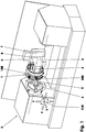
- the Figure 1 shows a lathe (3) which is equipped with a three-jaw chuck (4) and at least one tube magazine (1) with an internal spindle.
- the lathe (3) is, for example, a horizontal inclined bed machine, in the rear area of which the tube magazine (1) is possibly mounted on an x, y and z slide (8, 6, 7), while opposite the three-jaw chuck (4 ) a quill is arranged on its center line (5).
- the tube magazine (1) has a magazine tube body (100) which is rotatably mounted about the center line (2) of the tube magazine (1).
- a workpiece (9) is clamped in the three-jaw chuck (4) which, when the three-jaw chuck (4) is at a standstill, with a tool (500), for example a drill, cf. Figure 2 , is machined.
- the y-slide (6) moving in or out supports a z-slide (7) that can be moved up or down, which in turn supports the x-slide (8) that moves forward or backward with respect to the center line (5) and carries the tube magazine. Due to the three carriages (6-8), the tool (500) can be moved along the directions shown in the axles (510) on predeterminable straight or curved spatial curves, while the magazine's own spindle, cf. Figures 7 and 8th , allows a rotation around the y-axis.
- the tube magazine (1) is in Figure 3 shown as a single complete assembly with various tool holders (200, 230, 250, 380).
- the rotatable magazine tube body (100) with its front magazine tube support cover (105) can be seen.
- grid-shaped magazine tube body (100) there are eight Accumulator cover (110) installed.
- Each storage cover (110) represents an individual tool mounting location (131-138) and only stores a tool mounting (200, 230, 250, 270) or a tool holder (310, 340, 380) there, partially in Figure 7 shown, wherein the magazine tube body (100) has a tool receiving plane (101) in which the tool receiving places (131-138) are all distributed on the circumference and whose center lines lie both in the plane (101) and the center line (109) of the Cut the magazine tube body (100) at one point.
- FIGS. 1-10 are in the storage lids (110) - visibly lined up in a clockwise direction after a blind lid (370) - a manual clamp (230), a simple dynamic tool holder (200), another manual clamp (230), a tool assembly (250) and a static tool holder ( 380) arranged.
- tube magazine (1) can also be made longer along its center line (2) so that two, three or more tool receiving levels are created.
- the tubular magazine (1) has a central block (10) made from GGG 40, for example, as a base part, cf. Figure 4, 5 and 6th which, for example, consists essentially of a pin which is formed on a cuboid (11) and is at least partially cylindrical.
- the central block (10) is mounted on the square side, possibly as an x-slide (8) with its, for example, lateral fastening side (12), for example on the z-slide (7) of the lathe (3) carrying it. It has a large support base or surface on the z-slide (7).
- the height of the fastening surface of the cuboid (11) is greater than 75% of the maximum diameter of the rotatable magazine tube body (100), which results in a good supporting effect.
- the central block (10) has a large transverse recess (14) in which a work spindle (40) is installed.
- central block (10), cf. Figure 6 is arranged in the middle area of the magazine tube body (100) by means of an optionally multi-part, stationary base plate (107) on the rear with roller bearings and sealed.
- the base plate (107) is also sealed against the central block (10).
- the magazine tube body (100) To mount the magazine tube body (100) on the rear base plate (107), the latter carries the inner ring (33) of a needle bearing serving as a floating bearing, on whose rolling elements the magazine tube body (100) rests directly.
- the rotating needles are axially guided in a needle bearing inner ring (33).
- the magazine tube body (100) In the front area, the magazine tube body (100) is mounted via the magazine tube support cover (105) and a crossed roller bearing (25) or another roller bearing in the area of the end face (13).
- the roller bearing (25) serving as a fixed bearing is fastened axially to the journal (21) via a screw-on washer (22).
- the outer ring of the roller bearing (25) sits in a stepped bore (23) of the magazine tube support cover (105).
- the bore (23) is tightly closed by means of a bearing cover (106).
- the outer ring of the roller bearing (25) is axially clamped between the collar of the stepped bore (23) and a support collar present on the bearing cover (106), cf. Figure 6 .
- the base plate (107) has a sealing ring (34) at its outer edge area, for example at the level of the circumferential needles of the needle bearing inner ring (33).
- the sealing ring (34) which is a relatively dimensionally stable lip seal, rests on a finely machined one Sealing sliding surface of the magazine tube body (100).
- the sealing lip of the sealing ring (34) is oriented outwards.
- An electromechanical rotary drive (31) is located above the top of the cuboid (11), cf. Figures 1 , 2 to 6 which is flanged centered on the base plate (107). It comprises at least one angle measuring system, possibly a tachometer generator and a reduction gear.
- the gear output of the rotary drive (31) is a spur gear (32) which has a center line parallel to the central block center line (2), which at the same time forms a vertical longitudinal section center plane with the center line (109).
- the spur gear (32) the shaft of which penetrates the base plate (107) in a sealed manner, meshes with a ring gear (28) which is screwed to the magazine tube body (100) next to the needle bearing inner ring (33).
- the rotary drive (31) can be a servomotor which interacts with a spur gear, a planetary gear, an epicyclic gear with minimal play or a traction mechanism.
- the rotary drive (31) can also consist of a torque motor, a hydraulic or a pneumatic motor.
- the last two drives mentioned can be equipped with a latching or stepping mechanism, which also or only enables a clocked or discontinuous drive.
- a combination of different types of motors and / or transmissions is also conceivable.
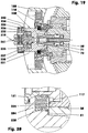
- the work spindle (40) mounted in the transverse recess (14) of the central block (10), cf. Figures 6 to 8 has a tubular motor housing (42), in the radial outer wall of which a spiral groove (43) is incorporated. In the spiral groove (43), which is given a closed channel cross section by the inner wall of the transverse recess (14), coolant for the Electric motor (90) out.
- the motor housing (42) has an inner flange (44) in the front area, against which, for example, two spindle-bearing shoulder bearings (46) arranged next to one another, for example via a spacer ring, rest axially.
- the stator (91) of the drive motor (90) rests on the rear face of the inner flange.
- the motor housing (42) supports a flange cover (47) with an outwardly facing inner collar in which a further shoulder bearing (48) is supported via a flange sleeve (49).
- the flange cover (47) has several axial blind bores in which helical compression springs are arranged which press the outer ring of the shoulder bearing (48) outwards over the flange sleeve (49).
- the shoulder bearings (46, 48) supporting the spindle shaft (50) are in an O-arrangement.
- a bearing seat (52) for the shoulder bearing (46) In front of the bearing seat (52) it has an external thread (53) onto which an axially tensioning threaded sleeve (56) resting on the inner ring of the outer shoulder bearing (46) is screwed.
- the latter has a threaded sleeve flange (57), cf.
- Figure 8 which has a multiple wraparound (58) to form a sealing air labyrinth seal.
- the multiple wraparound (58) partially encompasses an area of the front housing cover (60) with play.
- the housing cover (60) screwed onto the motor housing (42) surrounds the threaded sleeve (56) with radial play.
- the spindle shaft (50) On the front side, the spindle shaft (50) has a central conical recess (55) which belongs to a stepped bore (54) running through the spindle shaft (50) in the longitudinal direction.
- a balancing ring (62) On the spindle shaft (50) sits behind the front bearing seat (52) a balancing ring (62) with a cross press fit on a smaller diameter. It is followed by the rotor (92) opposite the stator (91). Another balancing ring sits between the rotor (92) and the rear flange cover (47) on the spindle shaft (50).
- a clamping cover (64) is screwed onto the rear end of the spindle shaft (50) and supports the rear shoulder bearing (48) via its inner ring.
- the clamping cover (64) is also a target wheel (65) used to determine the angle of rotation.
- a plate-spring-loaded collet (71) with its mandrel (72) Figure 8 for example up to the front in the vicinity of the end face (51) of the spindle shaft (50).
- the pull rod (72) is attached to a tie bolt (73) on which the disc springs (76) are lined up.
- the rear end of the tie rod screw (73) forms a disc spring stamp (74) which ends in a stamp cone (75) at the rear.
- the punch cone (75) has, for example, a cone angle of 16 ⁇ 6 degrees.
- a lubricant rotary feedthrough (80) is arranged in a centered manner.
- a hydraulically actuated annular piston (87) on which a base-like support cover (88) with a central bore rests towards the spindle shaft (50). If hydraulic oil is applied to the piston rear side remote from the spindle shaft, the support cover (88) rests on the cup spring ram (74) of the clamping device (70) in order to move the pull rod (72) in the opening direction.
- the housing (81) has a cover (84) which carries a central hollow pin (82) leading to the annular piston (87).
- the lubricant transfer shaft (83) is sealed with at least one sealing ring with respect to the bore of the longitudinally displaceable cup spring plunger (74).
- the rotating lubricant transfer shaft (83) has a tightly inserted sealing sleeve (85) with an axially oriented sliding surface on the rear. The latter rests axially on a spring-loaded or pressure-oil-loaded, longitudinally displaceable counter-sleeve (86).
- the mating sleeve (86) has a splash ring.
- the gas and / or liquid coolant and / or lubricant is supplied via this counter-sleeve (86) from the housing (81), the central cavities of the lubricant transfer shaft (83) and the tie rod screw (73). In this way, every dynamic or static tool holder can be supplied with the required coolant and / or lubricant.
- a sensor carrier plate (66) which is attached to the housing (81) and which carries a contactless sensor (67) for position detection, cf. Figure 8 .
- Sensor (67) measures the distance to the punch cone (75) of the disc spring punch (74).
- the longitudinal position of the collet chuck (71) is measured with the sensor (67) in order to be able to detect its various working positions or also non-intended working position deviations.
- the magazine tube body (100), cf. Figure 5 it is made of an aluminum alloy, has large, substantially rectangular, almost square storage lid recesses (141) on its circumference for the storage of storage lids (110), so that it has the shape of a cylindrical cage made up of two rings (102, 103 ) and, for example, eight, these connecting longitudinal struts (104).
- the longitudinal struts (104) have a first approximation trapezoidal cross-section. The cross-section tapers inwards, i.e. towards the center line (2).
- the front and rear walls of the smooth-walled storage cover recesses (141) lie in parallel planes which are, for example, 200 mm apart and which also intersect the center lines (2, 109) perpendicularly.
- the side walls of the storage lid recesses (141) - seen in the circumferential direction - are also located in two parallel planes, for example 190 mm apart, these planes each having the same shortest distance from the center line (2).
- the individual walls of a storage cover recess (141) merge into one another in a radius of, for example, 15 mm.
- the rear ring (102) has a width of, for example, 100 mm, while the front ring (103) measures 22 mm in width. Accordingly, the maximum distance between the tool receiving plane (101) and the front edge of the magazine tube body (100) is 148 mm.
- Two cantilevered support tongues (143, 144) protrude into the storage cover recesses (141) in the circumferential direction, for example 35 mm, which taper transversely to the center line (2) or in the circumferential direction towards the center of the respective storage cover recess (141), cf. Figure 5 .
- the depressions (146) here have a diameter of 32 mm.
- the upper sides (145) of both support tongues (143, 144) lie in one plane and are, for example, 62 mm away from the apex line (142) of the respective storage cover recess (141).
- the support tongues (143, 144) are offset from one another by 15 mm so that in Figure 5 the upper support tongue (143) is, for example, 73 mm away from the rear wall (148), while the lower support tongue (144) is only 58 mm apart.
- the outer diameter measures 620 mm with a radial wall thickness of 60 mm, for example.
- the polar moment of inertia of the magazine tube body (100), including the magazine tube support cover (105), is approx. 13.1 kgm 2 without the storage cover and tool holders.
- a substantially cuboid storage cover (110) is arranged so as to be radially movable with respect to the center line (109). It is made of a steel or aluminum alloy. It sits between the walls of the storage cover recess (141) with a clearance of 0.1 to 0.2 mm.
- a circumferential groove (112) which receives a sealing ring is incorporated into its lateral outer walls. The sealing ring On the one hand, it prevents dirt from penetrating into the interior (108) and, if necessary, on the other hand, it protects the tubular magazine from a greater drop in sealing air pressure.
- the storage cover (110) seated in the magazine tube body (100) has a stepped tool carrier bore (113) on the front side, that is to say on the outside.
- a stepped tool carrier bore (113) on the front side, that is to say on the outside.
- the single storage cover (110) is after Figure 7
- the storage cover (110) has - like the storage cover recesses (141) - four stepped rounded corner edges, the center lines of which are oriented parallel to the center lines of the tool carrier stepped bores (113).
- the first stage of the tool carrier step bore (113) is a countersink (114) for centered accommodation of a retaining ring (121), a holding plate (299, 361) or a small blind cover.
- the countersink (114) is followed by a radial play section (115).
- the latter is finally adjoined by the cylindrical end section (116) through which the threaded sleeve (56) of the spindle shaft (50) protrudes with play, for example when using dynamic tool holders (200, 230, 250, 270).
- Each end section (116) has at least three partial depressions (117) which are at least approximately sickle-shaped in cross section, in Figure 9 there are eight in which, at least in the case of the dynamic tool holders (200, 230, 250, 270), corresponding pitch positioning elements (220) engage, cf. Figure 18 .
- Each partial countersink (117) has a diameter of 10 mm, for example.
- the cylinder on which the center lines of the partial countersinks (117) lie around the center line of the tool carrier stepped bore (113) is, for example, 4 mm smaller than the inner diameter of the end section (116).
- Each storage cover (110) can have a gas and / or liquid coolant and / or lubricant supply in order to supply outwardly radiating coolant or lubricant nozzles built into the storage cover (110) - for cooling or lubricating the processing point.
- the storage cover (110) is hydraulically connected to the magazine tube body (100) or the central block (10), see line system (363) according to Figure 28 . If necessary, the centering and supporting device (190) or the storage cover clamping system (150) can also be used for this purpose.
- the magazine play of the flange (204) is essentially limited by the conical countersink (122) and the, for example, planar catch collar (119).
- the storage cover (110) only needs the countersink (114).
- the latter represents a flange-like receptacle shape (126), cf. Figure 24 .
- the storage cover (110) is connected to the central block (10) in a dimensionally stable manner by means of a storage cover clamping system (150) so that it can be switched or actuated.
- a storage cover clamping system 150
- the underside or rear side (152) of each storage cover (110), cf. Figure 10 for example two or more double feeder hooks (160).
- The, for example, two-armed fork (162) is formed on the cylindrical bearing pin (161) and ends at its free end in the two mutually converging rear grip hooks (164).
- Each double pull-in hook (160) sits over the base of the fork (162) in a side milled recess (155) so that it cannot rotate.
- the bearing pin (161) protrudes into a stepped bore (156) machined in the storage cover (110), cf. Figure 15 . It is held in it by means of the screw (165) which engages in an internal thread of the hollow bearing journal (161).
- the forks (162) are oriented with respect to their cuboid recess in such a way that their cross-section delimited by both fork arms (163) is oriented in the circumferential direction, cf. Figure 5 .
- the double pull-in hooks (160) can also be designed as single-armed, T-shaped hooks or the like.
- the respective counterpart to the double pull-in hooks (160) is a pull-in bolt (170), cf. Figures 13 , 15th and 4th .
- the draw-in bolt (170) is a cylinder bolt with a central through-hole, which has a countersink at the front and at the rear.
- the draw-in bolt (170) has grooves (171) lying opposite one another on both sides.
- the grooves (171) each of which has a rectangular cross-section, run perpendicular to the center line of the respective pull-in bolt (170).
- the bottoms of the two grooves (171) are parallel to one another.
- the two groove walls facing the screw head countersink are in one plane and are used to rest the rear grip hooks (164) of the respective pull-in double hooks (160), cf. Figure 13 . If necessary, these groove walls are designed to be spherical.
- the draw-in bolt (170) is mounted together with the double actuating piston (183) via a cylinder sleeve (173) in the central block (10) parallel to the center line (41) of the work spindle (40), cf. Figure 15 .
- the cylinder liner (173) is inserted with little play in a cylindrical blind hole (15) of the central block (10).
- Circumferential groove (174) also has, for example, a circumferential rectangular channel groove (175).
- a locking bolt (182) protrudes into the rectangular channel groove (175) and is screwed into a stepped threaded hole (18) of the central block (10) at the head stop.
- the lower end of the locking pin (182) is a cylindrical locking pin which engages with little play in the rectangular channel groove (175).
- the central bore of the cylinder liner (173) is essentially designed in four stages, with the diameter of the individual stepped areas decreasing towards the cylinder base (176).
- the first stepped area serves as a sealing and centering seat (177) of a first intermediate cylinder base (181).
- the cup-shaped intermediate cylinder base (181) is screwed into the second stepped area (178), which has an internal thread. It also has a central bore equipped with a seal, which is used to pass through the hollow piston rod (184) of the smaller first piston (185), for example.
- the latter (185) rests with its piston seal on the inner wall of the third area (179).
- the central bore of the piston (185) and the piston rod (184) have an internal thread on both sides. In the in Figure 15 The internal thread shown on the left sits the tension screw (172), which rigidly connects the draw-in bolt (170) to the piston rod (184).
- pressure medium is fed to the circumferential groove (174) via a longitudinal line (16) and a transverse line (17) in order to move from the circumferential groove (174) via at least one radial bore into the piston rod side of the first piston (185) located in front of the To get to the pressure chamber.
- Longitudinal bores (188) on the cylinder side open into one or more radial bores, through which the pressure medium can also flow into the pressure chamber arranged in front of the second piston (187).
- the double pull-in hooks (160) with the cylindrical bearing pin (161) are inserted and screwed in advance.
- the side milled recess (155) opens into a substantially rectangular longitudinal milled recess (153) several millimeters deep, the width of which is greater than 35.2 mm, while its length measures more than 69.2 mm.
- Two blind bores (154) lying next to one another, the diameter of which is 32 mm, for example, are machined into the longitudinal milled recess (153).
- the depth of the blind hole (154) is designed so that the remaining wall thickness in the area of the bottom of the hole is, for example, 2 mm.
- a spring element (139) for example in the form of a helical compression spring, is mounted in each blind hole (154).
- a tensioning system can also be used which, as tensioner in the central block (10), has a threaded bolt that can rotate about its center line and which can be screwed into a threaded hole in the storage lid (110) to clamp it.
- tensioner in the central block (10
- the front threaded end of the tensioner unscrews itself from the central block (10) in order to screw into the threaded hole of the storage cover (110) and pull it in a centering manner against stops on the central block (10).
- each longitudinal milled recess (153) on the underside (152) of the individual storage cover (110) - near the wall of the storage cover (110) oriented in the circumferential or circumferential direction - there is a support bolt (191) as part of a centering and supporting device ( 190) arranged.
- a support bolt (191) sits in a countersunk hole into which it protrudes in a centered manner, for example 8 mm deep, cf. Figure 16 .
- an internal thread by means of which the support bolt (191) is fastened in the storage cover (110) by means of a screw (194).
- the support bolt (191), cf. Figure 14 has at its free end a centering pin (192) which, for example, with a length of 10 mm has a diameter that is 4 mm smaller than the maximum diameter of the support bolt (191).
- the transition between the support bolt (191) and the centering pin (192) is designed as a finely machined, flat contact collar (193).
- the centering pin (192) can have an insertion bevel.
- the support bolt (191) is also part of a centering and supporting device (190) of the tubular magazine (1). Via the sum of the individual support bolts (191), the number of which per storage cover (110) can be greater than two, contrary to the exemplary embodiment, the storage cover (110) is supported on the central block (10) in a precise, repeatable and dimensionally stable manner.
- the repeat accuracy from docking to docking in the exemplary embodiment in the longitudinal direction of the spindle and transversely thereto is 5 ⁇ 2 ⁇ m.
- the support bolts (191) are each supported on a support sleeve (36) rigidly attached to the central block (10), cf. Figures 13 and 15th .
- the support sleeve (36) has a centering recess (37) in the rear area, with which it is centered in a counterbore provided with an internal thread in the central block (10). In the center it has a stepped through hole, the front area (38) of which receives the centering pin (192) of the support bolt (191) in a centering manner.
- the front area (38) is so deep that it can also accommodate the head of the screw (39) with which the support sleeve (36) is attached to the central block (10).
- two, three or more swivel lock systems (400) are built into each storage lid (110) . They are preferably arranged in the area of the storage cover walls which contact the longitudinal struts (104) of the magazine tube body (100).
- the single swivel lock system (400) consists of a T-shaped Stop bolt (401), a fixing screw (405) and a stop bolt (407), cf. Figures 11 and 12 .
- the T-shaped stop bar (401) comprises a tube (402) on which a transverse bar (403) is molded.
- the width of the crossbar (403) corresponds to the diameter of the tube (402).
- the crossbar (403) protrudes beyond the pipe (402) on both sides by a length that corresponds, for example, to the pipe diameter.
- the tube (402) here has a continuous internal thread.
- the stop bar (401) sits with little play in a stepped countersunk hole (408) in the storage cover (110). In the area of the bore, the stop bolt (401) rests with its cylindrical wall in a guided manner with little play.
- the cylindrical wall of the stop bar (401) ends a few tenths of a millimeter from the bottom of the depression (409) on which the head of the fixing screw (405) rests.
- the Figure 11 shows the swivel lock system (400) in the open state.
- the storage cover (110) can be taken out of the storage cover recess (141) radially with respect to the center line (109).
- the storage cover (110) is pushed out by the spring elements (139).
- the respective fixing screw (405) is loosened, for example, by one or two turns, see Figure 11 left, and the crossbar (403) is parallel to the construction joint (149) of the storage lid (110).
- the crossbar (403) is on the stop bolt (407), which is automatically obtained when the individual fixing screw (405) is loosened.
- the storage cover (110) is to be locked after being inserted into the storage cover recess (141), the storage cover (110) is pressed against the support tongues (143, 144).
- the fixing screws (405) are tightened one after the other, e.g. crosswise.
- the stop bolt (401) rotates to the right in order to screw the end of the transverse beam (403) closest to the construction joint (149) into an undercut groove (147) incorporated in the magazine tube body (100).
- the crossbar (403) again rests against the stop bolt (407), cf. Figure 12 .
- the storage cover (110) can be removed without further dismantling the tubular magazine (1), e.g. for maintenance purposes.
- the storage lids (110) can be fixed or secured in their magazine position (196) in addition or as an alternative to spring or gas pressure positioning, for example electromechanically, pneumatically or hydraulically. It is thus possible, for example, to install electromagnetic lifting cylinders in the rings (102, 103). Their lifting rams are aligned in such a way that their center lines are oriented parallel to the center line (109). To lock the individual storage lids (110) in the magazine position (196), for example, three lifting rams are extended per storage lid (109), which then engage in corresponding bores in the storage lid (110). Are the lifting rams guided in their lifting cylinders additionally equipped with a locking system that locks the lifting rams in their extended position in the lifting cylinder? can, let the lifting ram be kept de-energized in their end positions.
- a simple dynamic tool holder (200), cf. Figures 7 and 8th comprises, inter alia, a tool holder shaft (201) which - after being clamped in the spindle shaft (50) - is drawn with its cone (203) into the conical recess (55) of the spindle shaft (50) by means of the clamping device (70).
- the tool holder shaft (201) has a central recess (202) with a rear grip.
- the collet (71) of the clamping device (70) claws behind the latter.
- the tool holder shaft (201) has a flange (204) on the outside in the rear area, cf. Figure 18 with which it - even without being coupled to the spindle shaft (50) - is fixed in the corresponding recess (113) of the storage cover (110).
- the largely cylindrical flange (204) is chamfered on the front side, so that a centering surface (205) in the shape of a truncated cone is formed there. Your cone angle corresponds to the cone angle of the conical countersink (122) of the retaining ring (121).
- In the rear end face of the flange (204) there are at least two blind bores (206), as a rule there can also be 16 or more, for example with a flat bore bottom, cf. Figure 18 .
- a cup-shaped, for example a helical compression spring (225) or a plurality of cup springs (220) is slidably seated in each blind hole (206).
- the indexing positioning element (220) is inserted into the blind hole (206) in such a way that its base (221) is oriented towards the spindle shaft (50).
- the helical compression spring (225) tries here, the division positioning element (220) to push out of the blind hole (206).
- they have a collar (222) with which they are supported on the bore edges of a stop ring (207) screwed onto the rear of the flange (204).
- the bore edges belong to the bores from which the division positioning elements (220) protrude, cf. Figure 18 .
- short tabs can also be used which are screwed to the flange (204) on both sides of the individual blind hole (206) - in the circumferential direction of the drilling pattern.
- the sickle-shaped partial depressions (117) of the storage cover (110) lie coaxially opposite the blind bores (206), so that the division positioning elements (220) in the partial depressions (117) bear at least radially.
- the tool holder shaft (201) is positioned in the magazine tube body (100) so that it cannot rotate and, on the other hand, the helical compression springs (225) press the flange (204) in a centering manner against the retaining ring (121) via the pitch positioning elements (220).
- the front, flat end face of the flange (204) is pressed against the sealing ring (125).
- the bottom (123) of the countersink (122) has little play in relation to the front, flat end face of the flange (204).
- the interior space (108) of the multi-part magazine tube body (100, 105) is largely sealed off from the environment and is under 0.5 ⁇ 10 5 Pa positive air barrier pressure.
- the sealing air also presses the tool holders (200, 230, 250, 270) into the conical centerings of the retaining rings (121).
- FIG. 7 and 8th shows the tool holder shaft (201) of the simple, dynamic tool holder (200) outside of the magazine tube body (100), for example, a central conical recess (211) in which a collet (212) is used for clamping a twist drill (500) or the like.
- FIG. 17 to 22 the clamping of a dynamic tool holder (230) in the spindle shaft (50) is shown step by step.
- the Figure 17 shows the magazine tube body (100) in its rotational position.
- the storage cover (110) is still in its magazine position (196).
- he may have performed a 360 degree rotation around the center line (2) and / or (109) without having touched the central block (10) or the work spindle (40).
- the center lines (219, 41) of the tool holder (230) and the work spindle (40) are aligned.
- the mandrel (72) of the clamping device (70) is several tenths of a millimeter in front of the opening of the tool holder shaft (201) of the tool holder (230).
- the hook tongues of the collet (71) rest on the shaft of the pulling mandrel (72) pushed forward.
- the frustoconical centering surface (205) of the tool-receiving-side flange (204) lies tightly against the frustoconical surface of the depression (122) of the retaining ring (121).
- the dividing positioning elements (220) nestle in a form-fitting manner in the partial depressions (117) of the storage cover (110).
- the storage cover (110) together with the tool holder (230) was moved towards the spindle shaft (50) in a stroke of, for example, 22 mm.
- the collet (71) and the mandrel (72) protrude into the recess (202) of the tool holder shaft (201), but without the collet (71) looking forward to it.
- To Figure 20 does not the end face (51) of the spindle shaft (50) rest on the flange (204), nor does the wall of the conical recess (55) touch the outer cone (203) of the tool holder shaft (201).
- the flange (204) has its position opposite the retaining ring (121) at the transition from Figure 18 to Figure 20 not changed.
- the flange (204) loosens all around, cf. Figure 22 . It now rests neither on the retaining ring (121) nor on the storage cover (110). The sealing ring (125) does not contact the flange (204) either. The tool holder (230) is thus opposite the storage cover (110) freely movable.
- the magazine tube body (100) now has neither a carrying nor a guiding position.
- the gap between the tool holder (230) and the storage cover (110) has the function of a labyrinth seal, through which small volumes of sealing air - to avoid penetrating coolant and / or lubricant or other dirt - escape.
- the dynamic tool holder (230) with integrated hand clamp, cf. Figures 17 , 19th , 21 comprises a tool receiving shaft (201).
- the latter has a central stepped bore (231) in the outer face.
- a conical sleeve (232) is inserted in the large bore section with the largest diameter.
- the conical sleeve (232) is a stepped tubular body with a conical section (233) and a bayonet section (237).
- the conical inner wall of the conical section (233) serves to hold the tool.
- An annular cover (234) which can be adjusted by several degrees is guided on the radial outer wall of the conical section (233). It has, for example, two elongated guide holes for guidance on the conical sleeve (232), cf. Figure 3 .
- the heads of the guide screws (235) protrude into the latter.
- the bayonet section (237) protrudes into the large bore section of the tool holder (230) with a clearance of several tenths of a millimeter.
- the essentially cylindrical inner wall has at least one bayonet bar (238) for fixing a manual clamping insert (241).
- the conical sleeve (232) rests on its flat collar (236) on the outer end face of the tool holder shaft (201). There it is parallel to the center line of the tool holder (230) aligned screws. In the large bore section there are at least three threaded bores carrying threaded pins that are equidistantly distributed around the circumference. With the threaded pins, the conical sleeve (232) is aligned radially with respect to the center line of the tool holder (230) in order to optimize the tool run-out.
- the manual clamping insert (241) engages around the bayonet webs (238).
- the manual clamping insert (241), cf. Figure 19 is a bolt-shaped body which, at its rear end, has, for example, two webs for engaging behind the bayonet webs (238) of the conical sleeve (232). In the middle area it has two opposite transverse grooves (242). A clamping jaw (245) sits in each transverse groove (242).
- Each clamping jaw (245) has the shape of a segment of a circle in its cross-section, which is normal to the center line (219) of the tool holder (230).
- transverse grooves (242) there is a transverse bore into which a special threaded bolt (246) is inserted.
- Corresponding threaded bores are located in the clamping jaws (245) coaxially to this transverse bore.
- the special threaded bolt (246) has a right-hand thread on one side and a left-hand thread on the other. Each thread protrudes into a clamping jaw (245).
- the front of the special threaded bolt (246) has e.g. a tool recess for an Allen screwdriver.
- each clamping jaw (245) By turning the special threaded bolt (246), the clamping jaws (245) are extended or retracted synchronously with one another. Each clamping jaw (245) also has a wedge surface on which an ejector pin (247) rests with its wedge surface.
- the tool For manual clamping of the tool with the HSK tool shank, the tool is placed on the conical inner wall of the conical section (233).
- a tool recess in the special threaded bolt (246) By turning the ring cover (234) and the tool accordingly, a tool recess in the special threaded bolt (246), a hole in the HSK tool shank and a hole in the ring cover (234) are brought into line.
- the clamping jaws (245) With a subsequent turning of the special threaded bolt (246), the clamping jaws (245) are pressed against the inner contour of the recess of the HSK tool shank.
- the tool is now firmly seated in the tool holder (230).
- This tool holder (230) enables a free choice of interface.
- HSK®, Capto®, BENZ Solidfix® interfaces and the like can be implemented.
- FIG 23 a replaceable tool assembly (250) is shown.
- the tool assembly (250) which belongs to the group of dynamic tool holders, holds a twist drill (500) in a collet chuck (269), the center line of which is inclined by 30 degrees with respect to the center line of the drive shaft (263).
- the tool unit (250) supports the drive shaft (263) and an output shaft (267) carrying the collet (269) in a unit housing (261) with roller bearings.
- the drive shaft (263) drives a spur gear (268) of the output shaft (267) via a crown gear (264).
- angular gear units can also be used in which for example, bevel gears or helical gears in pairs are used. Worm gear sets or bevel helical gear pairs are also conceivable.
- the unit housing (261) is screwed to the corresponding storage cover (110) via a tubular retaining ring (257) by means of the screws (258), cf. Figure 7 .
- the tool holder shaft (251) encompassed by the tubular retaining ring (257) and the storage cover (110) has, opposite its HSK recess (252), a bore (253) provided with internal serration (254). This internal serration (254) engages in an external serration (265) attached to the drive shaft (263).
- a dynamic tool holder (270) is shown, with which a tool, which, for example, has an HSK interface (296), can be inserted and preloaded semi-automatically.
- the tool holder (270) has a tool holder shaft (271).
- the outer cone (203), the flange (204), the retaining ring (121) and the pitch positioning elements (220) are already known from the dynamic tool holders (200, 230) described above.
- the tool holder shaft (271) has a central stepped bore (272) on the spindle shaft side, in which a multi-part clamping adapter (290) is guided.
- the stepped bore (272) has a clamping sleeve guide zone (273) and a cylinder zone (277) with a smaller diameter.
- the multi-part clamping adapter (290) consists of a clamping sleeve (291), a piston rod section (292), a piston (293) and a collet holding section (294).
- the clamping sleeve (291) comprises the one provided with the rear grip Recess (202). With its outer contour, it is guided with little play in the stepped bore (272).
- the screwed-in piston rod section (292), for example, is attached to the clamping sleeve (291).
- a pretensioning ring (300) sits on the latter, the radial outer wall of which rests against the clamping sleeve guide zone (273).
- the prestressing ring (300) is supported on the plane surface (276) located between the clamping sleeve guide zone (273) and the cylinder zone (277).
- the pretensioning ring (300) is held axially in this position by a locking ring (278) which is seated in a locking ring groove (274) arranged in the clamping sleeve guide zone (273).
- the preload ring (300) has an O-ring (308) in its radial outer wall in an annular groove (303).
- the prestressing ring (300) has a large number of blind bores (302) in its end face (301) facing the clamping sleeve (291). In each blind hole (302) there is a helical compression spring (305) which is supported on the clamping sleeve (291).
- FIG. 25 which shows the semi-automatic tool holder (270) in a pneumatically relaxed state without an inserted HSK tool shank, the clamping sleeve (291) rests on the pretensioning ring (300). All helical compression springs (305) are compressed.
- the piston (293) At the front end of the piston rod section (292) is the piston (293), which is sealed off from the cylinder zone (277) by means of an O-ring. At the back of the Piston (293), facing the pretensioning ring (300), is pressurized.
- the compressed air is pumped into a system (128) made up of several bores by means of a compressed air blow gun via an elastomer adapter (127) located in the retaining ring (121). From there, the compressed air reaches the conical seat located between the retaining ring (121) and the flange (204).
- the frustoconical centering surface (205) has, in the area in which the system (128) ends, a circumferential annular groove (208) which is in operative connection with a further system (209) of bores.
- This system has a bore (209) which opens into the rear cylinder space (289) of the cylinder zone (277).
- the compressed air introduced via the system (209) pushes the clamping adapter (290) in Figure 26 to the left.
- the collet holding section (294) extends to the left of the piston (293).
- the latter has a waist around which a multi-part collet (295) is arranged with its hooked tongues.
- the collet holding section (294) widens in the manner of a truncated cone in order to be able to expand the collet (295) by means of the frustoconical surface.
- a conical sleeve (282) sits around the collet (295). It has a centering face groove (284) on the rear, in which an annular web (280) with a centering and external thread section (281) engages in a centering and fixing manner, which is arranged on the front face of the tool holder shaft (271).
- the conical sleeve (282) Towards the clamping adapter (290), the conical sleeve (282) has an inner cone (283) for fixing the position of the second interface.
- a positioning ring (286) In the rear area of the conical sleeve (282) there is a positioning ring (286) which is axially secured towards the front by a locking ring (287) snapped into an annular groove (285). The positioning ring (286) engages around the catch lugs of the hook tongues of the collet. It is sealed against the inner cone (283) by means of an O-ring (288).
- a single tool can be exchanged by the operator while the workpiece is being processed on the tube magazine (1), provided that the storage cover (110) of this tool is in a safely accessible location on the tube magazine (1).
- the operator grabs the tool in the magazine position with one hand, while he places a compressed air gun on the elastomer adapter (127) with the other.
- the clamping adapter moves pneumatically into its release position, cf. Figure 25 .
- the hook tongues of the collet chuck (295) rest against the collet chuck holding section (294) so that the tool can be pulled out of the inner cone (283) of the conical sleeve (282) without force.
- Figure 27 shows a static tool holder (310). This is firmly screwed into the relatively elastic magazine tube body (100) via a storage cover (110).
- the tool holder (310) generally has no mechanical connection to the work spindle (40).
- An exception can be transmission means, with the help of which, for example, lubricants and / or coolants are transferred from the work spindle to the tool holder.
- a base plate (299) is fastened to the storage cover (110), on which the base body (311) of the static tool holder (310) sits screwed in a bore, see also Figure 7 .
- the base body (311) has a stepped bore (312) in which the required clamping devices are located.
- a holder cone sleeve (313) In the front area of the stepped bore (312) there is a holder cone sleeve (313), on the inner wall of which the tool to be picked up rests.
- a clamping mandrel (315) carrying a collet chuck (317) is installed in the stepped bore (312).
- the mandrel (315) has a transverse transverse recess (316) behind the waist on which its collet (317) rests, through which a clamping shaft (320) mounted in the base body (311) passes.
- the tensioning shaft (320) which can be pivoted, for example, by 180 degrees, has cylindrical sections outside the transverse recess (316) with which it is slide-mounted in the base body (311).
- the transverse recess (316) it has the shape of a constant thickness (321), via which a tensioning displacement effect of the tensioning mandrel (315) results when the tensioning shaft (320) is rotated.
- a hexagonal recess (322) in the free end face.
- Figure 28 shows another static tool holder. It is a parallel gripper (340).
- the parallel gripper (340) has two gripping arms (355, 356) that can be closed and stored pneumatically, for example.
- workpieces can be picked up from the three-jaw chuck (3) in order to deposit them elsewhere or to pass them on in some other way.
- the parallel gripper (340) sits e.g. in the middle of a base plate (361), which in turn is fastened in the storage lid (110).
- the parallel gripper (340) has a recess (342) in a lower housing (341) which is closed at the bottom with a lower housing cover (348).
- the bottom (343) of the recess (342) has a bore.
- the piston rod (345) of an oval piston (344), for example, is guided in a sealed manner in the bore.
- the piston rod (345) carries a double-sided wedge hook (357) which is guided in an upper housing (351).
- a slide (353, 354) carrying a gripper arm (355, 356) is guided in the upper housing (351).
- the wedge hook (357) engages behind a front recess of the slide (353, 354) in a form-fitting manner with play.
- the wedge hook (357) and the carriages (353, 354) form two sliding wedge gears.
- the compressed air can also be fed to the storage cover (110) via the centering and support device (190), for example there via a hollow support bolt (191).
- electrical power and control signals can also be transported via the centering and supporting device (190) or the storage lid tensioning system (150).
- appropriate plugs and matching sockets in the respective counterparts (36, 160) are integrated.
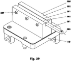
- a steel clamp (381) with a clamped turning tool (501) mounted on a storage cover (110) is shown as a static tool holder (380).
- the steel tensioner (381) is a cuboid body, in the top of which a channel (382) that is open at the top is incorporated.
- the turning chisel (501) is, for example, square-shaped
- the shaft (502) is rigidly attached with the aid of three clamping screws (389).
- the clamping screws (389) press the turning tool (501) against the duct wall opposite the duct wall in which the clamping screws (389) are screwed.
- the lower edge of the lathe chisel (501) is arranged so high above the top (151) of the storage lid (110) that it does not move into the storage lid recess (141) when the storage lid (110) is pulled into the storage lid recess (141) radial outer wall of the magazine tube carrier (100) contacted.
Description
Die Erfindung betrifft ein umlaufendes Rohrmagazin mit mehreren in einer Werkzeugaufnahmeebene liegenden Werkzeugaufnahmen, in dessen Innenraum eine Arbeitsspindel in einem werkzeugmaschinenseitig ortsfest angeordneten formsteifen Zentralblock gelagert ist.The invention relates to a revolving tube magazine with a plurality of tool holders located in a tool holder plane, in the interior of which a work spindle is mounted in a rigid central block arranged in a stationary manner on the machine tool side.
In den meisten Bearbeitungszentren, in denen zeitgleich mehrere vergleichbare Bearbeitungen durchgeführt werden, werden Revolverköpfe eingesetzt, die mehrere Werkzeugebenen aufweisen, vgl.
Aus der
Ein Werkzeugrevolver ist somit ein Träger von mehreren angetriebenen Werkzeugen. Auf seinem Basiskörper, z.B. einer Planscheibe oder einem Stern, sind Werkzeuge fest montiert und präzise ausgerichtet. Der Basiskörper, das zentrale Bauteil des Werkzeugrevolvers, leitet die am Werkzeug entstehenden Bearbeitungskräfte und -momente direkt an die Werkzeugmaschine weiter. Der Basiskörper muss folglich so formsteif sein, dass es beim Werkzeug - während des Bearbeitungsvorganges - an der Werkzeugschneide nicht zu Positionsabweichungen kommt. Der Träger bewerkstelligt somit das Halten der Werkzeugposition unter Bearbeitungsbelastung. Zudem müssen bei Revolverköpfen die Werkzeugaufnahmen nach jedem Austausch neu ausgerichtet werden.A tool turret is therefore a carrier for several driven tools. Tools are firmly mounted and precisely aligned on its base, for example a faceplate or a star. The base body, the central component of the tool turret, transfers the machining forces and torques generated on the tool directly to the machine tool. The base body must consequently be dimensionally stable so that the tool does not deviate from the position of the tool cutting edge during the machining process. The carrier thus manages the holding of the tool position under the machining load. In addition, must with turret heads the tool holders are realigned after each replacement.
Aus der
Der vorliegenden Erfindung liegt das Problem zugrunde, ein umlaufendes Rohrmagazin zu entwickeln, das räumlich vor einer Arbeitsspindel eine bestimmbare werkzeugtragende Werkzeugaufnahme und/oder ein bestimmtes Werkzeug wiederholgenau - bei kurzer Werkzeugwechselzeit - zum Einspannen und Antreiben positionieren kann.The present invention is based on the problem of developing a rotating tube magazine that can position a determinable tool-bearing tool holder and / or a specific tool in front of a work spindle with repeatable accuracy - with a short tool change time - for clamping and driving.
Das Problem wird mit den Merkmalen des Patentanspruchs 1 gelöst. Dazu weist der Zentralblock zur Aufnahme der Werkzeugaufnahmen und/oder Werkzeuge - in jeweils einem Werkzeugaufnahmeplatz - einen ein- oder mehrteiligen Magazinrohrkörper auf. Der Magazinrohrkörper ist um den Zentralblock angetrieben, rotierbar wälz- und/oder gleitgelagert. Der Magazinrohrkörper weist pro Werkzeugaufnahmeplatz einen Speicherdeckel zur Magazinierung einer Werkzeugaufnahme und/oder eines Werkzeuges auf. Der Speicherdeckel ist mit der für die Werkstückbearbeitung erforderlichen Werkzeugaufnahme und/oder dem erforderlichen Werkzeug am Zentralblock vor der vorderen Stirnseite der Arbeitsspindel in Umlaufrichtung des Magazinrohrkörpers - in einer Arbeitsposition - zum Andocken am Zentralblock und/oder zum Ankuppeln der Werkzeugaufnahme und/oder des Werkzeugs an der Arbeitsspindel positionierbar.The problem is solved with the features of
Ein Werkzeugmagazin in Form des beschriebenen Rohrmagazins gilt als Peripheriegerät einer Werkzeugmaschine. Es dient der Aufbewahrung bzw. "Speicherung" der Werkzeugaufnahmen und/oder der Werkzeuge, die die Werkzeugmaschine, z.B. eine Drehmaschine, gerade nicht im Einsatz hat. Im vorliegenden Beispiel wird ein ausgewähltes Werkzeug durch eine Magazindrehung und eine lineare Verlagerung des auf einem Speicherdeckel gelagerten Werkzeugs, vor die im Zentralblock angeordnete - nicht längsverschiebbare - Arbeitsspindel gebracht. Im Werkzeugmagazin sind die Werkzeuge in einem Magazinrohrkörper nur so genau abgelegt, dass die Arbeitsspindel sie - nach dem Heranführen des Speicherdeckels und dessen Absetzen am Zentralblock - aufnehmen kann. Erst nachdem die Arbeitsspindel das entsprechende Werkzeug mit seinem Spannmittel übernommen hat, ist das Werkzeug in der Drehmaschine präzise und wiederholgenau positioniert. Die Arbeitsspindel leitet über ihr im Zentralblock sitzendes Gehäuse die Bearbeitungskräfte an die Werkzeugmaschine ab. Die werkzeugspeichernden Aufbewahrungsplätze des Magazins umgeben mit großem Spiel das rotierende Werkzeug, ohne dieses zu stützen oder in sonstiger Weise zu beeinflussen.A tool magazine in the form of the tubular magazine described is considered a peripheral device of a machine tool. It is used to keep or "store" the tool holders and / or the tools that the machine tool, for example a lathe, is not currently using. In the present example, a selected tool is brought in front of the - not longitudinally displaceable - work spindle arranged in the central block by a magazine rotation and a linear displacement of the tool stored on a storage cover. In the tool magazine, the tools are stored in a magazine tube body so precisely that the work spindle can pick them up after the storage cover has been brought up and placed on the central block. Only after the work spindle has taken over the corresponding tool with its clamping device is the tool positioned in the lathe precisely and with repeatability. The work spindle transfers the machining forces to the machine tool via its housing located in the central block. The tool-storing storage spaces of the magazine surround the rotating tool with great play, without supporting it or influencing it in any other way.
Das Werkzeugmagazin kann neben dynamischen Werkzeugen auch statische Werkzeugaufnahmen bzw. -halter oder Werkzeuge speichern, die nicht von der Arbeitsspindel angetrieben werden, wie z.B. einen Drehmeißel oder eine Greifvorrichtung. Sind die Werkzeugaufnahmen oder Werkzeuge aus ihrer Magazinposition in die Arbeitsposition geschwenkt worden, werden diese über ihren Speicherdeckel, auf dem sie in der Regel starr montiert oder angeformt sind, am Zentralblock formsteif aber lösbar angedockt. Somit werden alle auf das Werkzeug wirkenden Kräfte direkt über Speicherdeckel in den Zentralblock und von da an die Werkzeugmaschine weitergeleitet.In addition to dynamic tools, the tool magazine can also store static tool holders or tool holders or tools that are not driven by the work spindle, such as a lathe chisel or a gripping device. If the tool holders or tools have been pivoted from their magazine position into the working position, they are docked on the central block in a dimensionally stable but detachable manner via their storage cover, on which they are usually rigidly mounted or molded. In this way, all forces acting on the tool are transferred directly to the central block via the storage cover and from there to the machine tool.
Da der Magazinrohrkörper während der Werkstückbearbeitung keine Funktion hat, muss er zum einen nur die Gewichtskräfte der in ihm abgelegten Werkzeugaufnahmen und Werkzeuge tragen. Zum anderen muss er nur so formsteif und schwenkgenau sein, dass der Zentralblock die Speicherdeckel und die Arbeitsspindel die ausgewählte Werkzeugaufnahme, jeweils mit ihren speziellen Spannmitteln, ergreifen können. Dadurch kann der Magazinrohrkörper - im Vergleich zum werkzeugtragenden Kopf eines Revolvers - dünnwandig und/oder elastisch ausgeführt sein. Es können für den Magazinrohrkörper Werkstoffe eingesetzt werden, deren jeweiliger E-Modul unterhalb von 80000 N/mm2 liegt. Somit sind als Werkstoffe Aluminiumlegierungen oder auch Verbundwerkstoffe auf Glasfaser- oder Kohlefaserbasis denkbar. In der Folge lässt sich das polare Massenträgheitsmoment des Magazinrohrkörpers - gegenüber eines in den Außenabmessungen vergleichbaren Revolverkopfes - aufgrund der geringeren Wandstärken und/oder der geringeren Werkstoffdichte um mehr als den Faktor 5 absenken. Das wirkt sich direkt auf die Dynamik des Magazins aus. Eine 360-Winkelgraddrehung erlaubt gegenüber einem konventionellen Revolver eine Drehzahlerhöhung um das Mehrfache.Since the magazine tube body has no function during workpiece machining, it only has to bear the weight of the tool holders and tools stored in it. On the other hand, it only has to be dimensionally stable and swivel-accurate so that the central block, the storage cover and the work spindle can grip the selected tool holder, each with its special clamping device. As a result, the magazine tube body - in comparison to the tool-carrying head of a revolver - can be made thin-walled and / or elastic. For the magazine tube body, materials can be used whose respective modulus of elasticity is below 80,000 N / mm 2 . Thus, aluminum alloys or composite materials based on glass fiber or carbon fiber are conceivable as materials. As a result, the polar moment of inertia of the magazine tube body can be reduced by more than a factor of 5 due to the smaller wall thicknesses and / or the lower material density compared to a turret head with comparable external dimensions. This has a direct effect on the dynamics of the magazine. A 360 degree rotation allows a multiple increase in speed compared to a conventional turret.
Das Rohrmagazin ist u.a. für den Einsatz in Drehmaschinen geeignet, da der Abstand zwischen der Ebene, in der sich zumindest bei dynamischen Werkzeugaufnahmen die Mittellinie des jeweils rotierenden Werkzeugs befindet, und der Vorderkante des Magazinrohrkörpers (100) eine Länge hat, die kleiner ist als 25% des maximalen Durchmessers des Magazinrohrkörpers (100). Bei der Größenangabe des Durchmessers - die auch für andere relative Längenverhältnissangaben gilt - wird die Auskraglänge der Werkzeugaufnahmen und der Werkzeuge nicht berücksichtigt.The tube magazine is suitable for use in lathes, among other things, since the distance between the plane in which the center line of the rotating tool is located, at least in the case of dynamic tool holders, and the front edge of the magazine tube body (100) has a length that is less than 25 % of the maximum diameter of the magazine tube body (100). When specifying the size of the diameter - which also applies to other relative length ratio specifications - the overhang length of the tool holders and the tools is not taken into account.
Weitere Einzelheiten der Erfindung ergeben sich aus den Unteransprüchen und den nachfolgenden Beschreibungen von schematisch dargestellten Ausführungsformen.
- Figur 1:
- Perspektivische Ansicht einer mit einem Rohrmagazin ausgestatteten Drehmaschine;
- Figur 2:
- Detail aus
Figur 1 - Figur 3:
- Perspektivische Ansicht des Rohrmagazins;
- Figur 4:
- Perspektivische Ansicht des Rohrmagazins ohne Magazinrohrkörper, Magazinstützdeckel und Kreuzrollenlager;
- Figur 5:
- wie
Figur 4Figur 4 - Figur 6:
- Längsschnitt des Rohrmagazins;
- Figur 7:
- Querschnitt des Rohrmagazins mit Werkzeugaufnahmen;
- Figur 8:
- Längsschnitt einer Arbeitsspindel;
- Figur 9:
- Speicherdeckel von schräg oben;
- Figur 10:
- Speicherdeckel von schräg unten;
- Figur 11:
- Längsschnitt des speicherdeckelseitigen Anschlagriegels, offen, vergrößert;
- Figur 12:
wie Figur 11 , jedoch geschlossen;- Figur 13:
- Perspektivische Ansichten des Einzugdoppelhakens und des Einzugsbolzens;
- Figur 14:
- Perspektivische Ansicht der Stützhülse und des Stützbolzens;
- Figur 15:
- Querschnittsausschnitt des Rohrmagazins im Bereich des Einzugdoppelhakens;
- Figur 16:
- Querschnittsausschnitt des Rohrmagazins im Bereich der Stützhülse;
- Figur 17:
- Teilschnitt durch das Rohrmagazin bei nicht herangezogenem Speicherdeckel und bei nicht adaptierter Werkzeugaufnahme;
- Figur 18:
- vergrößertes Detail zu
Figur 17 ; - Figur 19:
- Teilschnitt durch das Rohrmagazin bei herangezogenem Speicherdeckel und herangeführter, aber noch nicht adaptierter Werkzeugaufnahme;
- Figur 20:
- vergrößertes Detail zu
Figur 19 ; - Figur 21:
- Teilschnitt durch das Rohrmagazin wie
Figur 19 , jedoch mit adaptierter Werkzeugaufnahme; - Figur 22:
- vergrößertes
Detail zu Figur 21 ; - Figur 23:
- Schnitt durch ein Werkzeugaggregat;
- Figur 24:
- Schnitt durch einen Speicherdeckel und einen Haltering;
- Figur 25:
- Halbschnitt durch eine dynamische Werkzeugaufnahme für einen halbautomatischen Werkzeugwechsel, vergrößert;
- Figur 26:
Teilschnitt zu Figur 25 mit gespannter Schnittstelle ohne eingewechseltes Werkzeug;- Figur 27:
- Schnitt durch eine statische Werkzeugaufnahme mit einer HSK-Werkzeugaufnahme;
- Figur 28:
- Schnitt durch eine statische Werkzeugaufnahme in Form eines Parallelgreifers;
- Figur 29:
- Perspektivische Ansicht eines Speicherdeckels mit Drehmeißel.
- Figure 1:
- Perspective view of a lathe equipped with a tube magazine;
- Figure 2:
- Detail
Figure 1 ; - Figure 3:
- Perspective view of the tube magazine;
- Figure 4:
- Perspective view of the tube magazine without the magazine tube body, magazine support cover and crossed roller bearing;
- Figure 5:
- how
Figure 4 , but at 90 ° oppositeFigure 4 rotated and additionally with magazine tube body; - Figure 6:
- Longitudinal section of the tube magazine;
- Figure 7:
- Cross section of the tube magazine with tool holders;
- Figure 8:
- Longitudinal section of a work spindle;
- Figure 9:
- Storage lid from diagonally above;
- Figure 10:
- Storage lid from diagonally below;
- Figure 11:
- Longitudinal section of the storage cover-side stop bolt, open, enlarged;
- Figure 12:
- how
Figure 11 , but closed; - Figure 13:
- Perspective views of the pull-in double hook and the pull-in bolt;
- Figure 14:
- Perspective view of the support sleeve and the support bolt;
- Figure 15:
- Cross-sectional detail of the tubular magazine in the area of the double retraction hook;
- Figure 16:
- Cross-sectional detail of the tubular magazine in the area of the support sleeve;
- Figure 17:
- Partial section through the tube magazine with the storage cover not pulled in and with the tool holder not adapted;
- Figure 18:
- enlarged detail too
Figure 17 ; - Figure 19:
- Partial section through the tube magazine with the storage cover pulled in and the tool holder brought up but not yet adapted;
- Figure 20:
- enlarged detail too
Figure 19 ; - Figure 21:
- Partial section through the pipe magazine like
Figure 19 , but with adapted tool holder; - Figure 22:
- enlarged detail too
Figure 21 ; - Figure 23:
- Section through a tool unit;
- Figure 24:
- Section through a storage cover and a retaining ring;
- Figure 25:
- Half section through a dynamic tool holder for a semi-automatic tool change, enlarged;
- Figure 26:
- Part cut to
Figure 25 with clamped interface without exchanged tools; - Figure 27:
- Section through a static tool holder with an HSK tool holder;
- Figure 28:
- Section through a static tool holder in the form of a parallel gripper;
- Figure 29:
- Perspective view of a storage cover with a lathe chisel.
Die
Der heraus- oder hineinfahrende y-Schlitten (6) lagert einen rauf- oder runterbeweglichen z-Schlitten (7), der wiederum den bezüglich der Mittellinie (5) vor- oder zurückfahrenden, rohrmagazintragenden x-Schlitten (8) lagert. Aufgrund der drei Schlitten (6 - 8) lässt sich das Werkzeug (500) entlang der im Achsenkreuz (510) dargestellten Richtungen auf vorgebbaren geraden oder gekrümmten Raumkurven verfahren, während die magazineigene Spindel, vgl.
Das Rohrmagazin (1) wird in
Selbstverständlich kann das Rohrmagazin (1) entlang seiner Mittellinie (2) auch länger gebaut werden, so dass zwei, drei oder mehr Werkzeugaufnahmeebenen entstehen.Of course, the tube magazine (1) can also be made longer along its center line (2) so that two, three or more tool receiving levels are created.
Das Rohrmagazin (1) hat als Basisteil einen z.B. aus GGG 40 gefertigten Zentralblock (10), vgl.
Der Zentralblock (10) weist im Ausführungsbeispiel eine große Querausnehmung (14) auf, in der eine Arbeitsspindel (40) eingebaut ist.In the exemplary embodiment, the central block (10) has a large transverse recess (14) in which a work spindle (40) is installed.
An dem Zentralblock (10), vgl.
Zur Lagerung des Magazinrohrkörpers (100) an der hinten liegenden Basisplatte (107) trägt Letztere den Innenring (33) eines als Loslager dienenden Nadellagers, auf dessen Wälzkörper der Magazinrohrkörper (100) direkt aufliegt. Die umlaufenden Nadeln werden axial geführt in einem Nadellagerinnenring (33). Im vorderen Bereich ist der Magazinrohrkörper (100) über den Magazinrohrstützdeckel (105) und ein Kreuzrollenlager (25) oder einem anderen Wälzlager im Bereich der Stirnseite (13) gelagert. Dazu befindet sich an der Stirnseite (13) ein z.B. gestufter Zapfen (21), auf dem das Wälzlager (25) mit seinem Innenring sitzt. Das als Festlager dienende Wälzlager (25) ist über eine Anschraubscheibe (22) axial am Zapfen (21) befestigt. Der Außenring des Wälzlagers (25) sitzt in einer gestuften Bohrung (23) des Magazinrohrstützdeckels (105). Die Bohrung (23) ist mittels eines Lagerdeckels (106) dicht verschlossen. Zwischen dem Bund der gestuften Bohrung (23) und einem am Lagerdeckel (106) vorhandenen Stützkragen ist der Außenring des Wälzlagers (25) axial eingespannt, vgl.
Die Basisplatte (107) weist z.B. in der Höhe der umlaufenden Nadeln des Nadellagerinnenrings (33) an ihrem äußeren Randbereich einen Dichtring (34) auf. Der Dichtring (34), der eine relativ formsteife Lippendichtung ist, liegt an einer fein bearbeiteten Dichtgleitfläche des Magazinrohrkörpers (100) an. Die Dichtlippe des Dichtrings (34) ist nach außen orientiert.The base plate (107) has a sealing ring (34) at its outer edge area, for example at the level of the circumferential needles of the needle bearing inner ring (33). The sealing ring (34), which is a relatively dimensionally stable lip seal, rests on a finely machined one Sealing sliding surface of the magazine tube body (100). The sealing lip of the sealing ring (34) is oriented outwards.
Über der Oberseite des Quaders (11) befindet sich ein elektromechanischer Rotationsantrieb (31), vgl.
Der Rotationsantrieb (31) kann ein Servomotor sein, der mit einem Stirnradgetriebe, einem Plantengetriebe, einem spielminimierten Umlaufgetriebe oder einem Zugmittelgetriebe zusammenwirkt. Alternativ kann der Rotationsantrieb (31) auch aus einem Torquemotor, einem Hydraulik- oder einem Pneumatikmotor bestehen. Die beiden letztgenannten Antriebe können mit einem Rast- oder Schrittschaltmechanismus ausgestattet sein, der auch oder nur einen getakteten bzw. diskontinuierlichen Antrieb ermöglicht. Ferner ist auch eine Kombination verschiedener Motoren- und/oder Getriebearten denkbar.The rotary drive (31) can be a servomotor which interacts with a spur gear, a planetary gear, an epicyclic gear with minimal play or a traction mechanism. Alternatively, the rotary drive (31) can also consist of a torque motor, a hydraulic or a pneumatic motor. The last two drives mentioned can be equipped with a latching or stepping mechanism, which also or only enables a clocked or discontinuous drive. A combination of different types of motors and / or transmissions is also conceivable.
Die in der Querausnehmung (14) des Zentralblocks (10) gelagerte Arbeitsspindel (40), vgl.
Das Motorengehäuse (42) lagert an seinem hinteren Ende einen Flanschdeckel (47) mit einem nach außen weisenden Innenbund, in dem über eine Flanschhülse (49) ein weiteres Schulterlager (48) gelagert ist. Der Flanschdeckel (47) weist mehrere axiale Sacklochbohrungen auf, in denen Schraubendruckfedern angeordnet sind, die den Außenring des Schulterlagers (48) über die Flanschhülse (49) nach außen pressen. Die die Spindelwelle (50) lagernden Schulterlager (46, 48) befinden sich in O-Anordnung.At its rear end, the motor housing (42) supports a flange cover (47) with an outwardly facing inner collar in which a further shoulder bearing (48) is supported via a flange sleeve (49). The flange cover (47) has several axial blind bores in which helical compression springs are arranged which press the outer ring of the shoulder bearing (48) outwards over the flange sleeve (49). The shoulder bearings (46, 48) supporting the spindle shaft (50) are in an O-arrangement.
Die hohle Spindelwelle (50), deren Durchmesser sich von vorn nach hinten stufenweise verjüngt, weist vorn - im Bereich des Spindelkopfs - einen Lagersitz (52) für die Schulterlager (46) auf. Vor dem Lagersitz (52) hat sie ein Außengewinde (53), auf dem eine am Innenring des äußeren Schulterlagers (46) anliegende axial spannende Gewindehülse (56) aufgeschraubt ist. Letztere hat einen Gewindehülsenflansch (57), vgl.
Stirnseitig weist die Spindelwelle (50) vorn eine zentrale konische Ausnehmung (55) auf, die zu einer die Spindelwelle (50) in Längsrichtung durchlaufende Stufenbohrung (54) gehört. Auf der Spindelwelle (50) sitzt hinter dem vorderen Lagersitz (52) auf kleinerem Durchmesser ein Auswuchtring (62) per Querpresssitz. Ihm folgt der dem Stator (91) gegenüberliegende Rotor (92). Ein weiterer Auswuchtring sitzt zwischen dem Rotor (92) und dem hinteren Flanschdeckel (47) auf der Spindelwelle (50).On the front side, the spindle shaft (50) has a central conical recess (55) which belongs to a stepped bore (54) running through the spindle shaft (50) in the longitudinal direction. On the spindle shaft (50) sits behind the front bearing seat (52) a balancing ring (62) with a cross press fit on a smaller diameter. It is followed by the rotor (92) opposite the stator (91). Another balancing ring sits between the rotor (92) and the rear flange cover (47) on the spindle shaft (50).
Auf dem hinteren Ende der Spindelwelle (50) ist ein Spanndeckel (64) angeschraubt, der das hintere Schulterlager (48) über dessen Innenring abstützt. Der Spanndeckel (64) ist zugleich ein für die Drehwinkelbestimmung verwendetes Messzahnrad (65).A clamping cover (64) is screwed onto the rear end of the spindle shaft (50) and supports the rear shoulder bearing (48) via its inner ring. The clamping cover (64) is also a target wheel (65) used to determine the angle of rotation.
In der Stufenbohrung (54) der Spindelwelle (50) sitzt im Bereich des Spindelkopfes eine tellerfederbelastete Spannzange (71), deren Zugdorn (72), nach
Am hinteren Ende der Arbeitsspindel (40) ist eine Schmiermitteldrehdurchführung (80) zentriert angeordnet. Im Gehäuse (81) der Drehdurchführung (80) sitzt ein hydraulisch betätigbarer Ringkolben (87), an dem zur Spindelwelle (50) hin ein bodenartiger Stützdeckel (88) mit zentraler Bohrung anliegt. Wird die spindelwellenferne Kolbenrückseite mit Hydrauliköl beaufschlagt, legt sich der Stützdeckel (88) am Tellerfederstempel (74) der Spannvorrichtung (70) an, um den Zugdorn (72) in Öffnungsrichtung zu verschieben. Bei einem Umlenken des Hydrauliköldrucks auf die spindelwellennahe Kolbenstangenseite des Ringkolbens (87) läuft der Ringkolben (87) zurück, damit die Spannzange (71) federbelastet wieder in ihre Schließstellung übergehen kann. Um diese Position zu Steuerungszwecken erfassen zu können, ist außen am Stützdeckel (88) ein z.B. scheibenartiger Schaltkragen (89) angeordnet. Letzterer gelangt beim Entspannen der Tellerfedern (76) in den Bereich des am Gehäuse (81) angebauten Näherungsschalters (79).At the rear end of the work spindle (40) a lubricant rotary feedthrough (80) is arranged in a centered manner. In the housing (81) of the rotary feedthrough (80) sits a hydraulically actuated annular piston (87) on which a base-like support cover (88) with a central bore rests towards the spindle shaft (50). If hydraulic oil is applied to the piston rear side remote from the spindle shaft, the support cover (88) rests on the cup spring ram (74) of the clamping device (70) in order to move the pull rod (72) in the opening direction. When the hydraulic oil pressure is diverted to the piston rod side near the spindle shaft of the annular piston (87), the annular piston (87) runs back so that the collet (71) can return to its closed position in a spring-loaded manner. In order to be able to detect this position for control purposes, a, for example, disk-like switching collar (89) is arranged on the outside of the support cover (88). When the disc springs (76) are released, the latter reaches the area of the proximity switch (79) attached to the housing (81).
Das Gehäuse (81) weist einen Deckel (84) auf, der einen zentralen - den Ringkolben (87) führenden - Hohlzapfen (82) trägt. Im verdrehgesicherten Hohlzapfen (82) sitzt wälzgelagert eine hohle Schmiermittelübergabewelle (83), die in die zentrale Bohrung des Tellerfederstempels (74) hineinragt. Die Schmiermittelübergabewelle (83) ist gegenüber der Bohrung des längsverschiebbaren Tellerfederstempels (74) mit mindestens einem Dichtring abgedichtet.The housing (81) has a cover (84) which carries a central hollow pin (82) leading to the annular piston (87). A hollow lubricant transfer shaft (83), which protrudes into the central bore of the cup spring plunger (74), sits on roller bearings in the torsion-proof hollow pin (82). The lubricant transfer shaft (83) is sealed with at least one sealing ring with respect to the bore of the longitudinally displaceable cup spring plunger (74).
Die rotierende Schmiermittelübergabewelle (83) weist rückseitig eine dicht eingesteckte Dichthülse (85) mit einer axial orientierten Gleitfläche auf. Letztere liegt axial an einer feder- oder druckölbelasteten, längsverschiebbaren Gegenhülse (86) an. Die Gegenhülse (86) weist einen Spritzring auf.The rotating lubricant transfer shaft (83) has a tightly inserted sealing sleeve (85) with an axially oriented sliding surface on the rear. The latter rests axially on a spring-loaded or pressure-oil-loaded, longitudinally displaceable counter-sleeve (86). The mating sleeve (86) has a splash ring.
Über diese Gegenhülse (86) wird aus dem Gehäuse (81), den zentralen Hohlräumen der Schmiermittelübergabewelle (83) und der Zugankerschraube (73) das gas- und/oder flüssige Kühl- und/oder Schmiermittel zugeführt. Auf diese Weise kann jede dynamische oder statische Werkzeugaufnahme mit dem geforderten Kühl- und/oder Schmiermittel versorgt werden.The gas and / or liquid coolant and / or lubricant is supplied via this counter-sleeve (86) from the housing (81), the central cavities of the lubricant transfer shaft (83) and the tie rod screw (73). In this way, every dynamic or static tool holder can be supplied with the required coolant and / or lubricant.
Zwischen der Schmiermitteldrehdurchführung (80) und dem Messzahnrad (65) befindet sich eine am Gehäuse (81) befestigte Sensorträgerplatte (66), die einen berührungslos arbeitenden Sensor (67) zur Positionserfassung trägt, vgl.
Der Magazinrohrkörper (100), vgl.
Der hintere Ring (102) hat eine Breite von z.B. 100 mm, während der vordere Ring (103) bezüglich der Breite 22 mm misst. Demnach beträgt der maximale Abstand zwischen der Werkzeugaufnahmeebene (101) und der Vorderkante des Magazinrohrkörpers (100) 148 mm.The rear ring (102) has a width of, for example, 100 mm, while the front ring (103) measures 22 mm in width. Accordingly, the maximum distance between the tool receiving plane (101) and the front edge of the magazine tube body (100) is 148 mm.
In die Speicherdeckelausnehmungen (141) ragen in Umfangsrichtung jeweils zwei freikragende Abstützzungen (143, 144) um z.B. 35 mm hinein, die sich quer zur Mittellinie (2) bzw. in Umfangsrichtung in Richtung der Mitte der jeweiligen Speicherdeckelausnehmung (141) verjüngen, vgl.
Die z.B. 69 mm breiten Abstützzungen (143, 144) haben beide eine Oberseite (145), in die je zwei Einsenkungen (146) zur Lagerung von Federelementen (139) nebeneinander angeordnet sind. Die Einsenkungen (146) haben hier einen Durchmesser von 32 mm. Die Oberseiten (145) beider Abstützzungen (143, 144) liegen in einer Ebene und sind von der Scheitellinie (142) der jeweiligen Speicherdeckelausnehmung (141) z.B. 62 mm entfernt. Die Abstützzungen (143, 144) sind gegeneinander um 15 mm versetzt, so dass in
Im Ausführungsbeispiel misst der Außendurchmesser 620 mm bei einer radialen Wandstärke von z.B. 60 mm. Das polare Massenträgheitsmoment des Magazinrohrkörpers (100), einschließlich des Magazinrohrstützdeckels (105), beträgt ohne Speicherdeckel und Werkzeugaufnahmen ca. 13,1 kgm2.In the exemplary embodiment, the outer diameter measures 620 mm with a radial wall thickness of 60 mm, for example. The polar moment of inertia of the magazine tube body (100), including the magazine tube support cover (105), is approx. 13.1 kgm 2 without the storage cover and tool holders.
In der jeweiligen Speicherdeckelausnehmung (141), vgl.
In der Regel hat der im Magazinrohrkörper (100) sitzende Speicherdeckel (110) stirnseitig, also außen, eine Werkzeugträgerstufenbohrung (113). In dem einzelnen Speicherdeckel (110) ist nach
Der Speicherdeckel (110) hat - wie die Speicherdeckelausnehmungen (141) - vier gestuft abgerundete Eckkanten, deren Mittellinien parallel zu den Mittellinien der Werkzeugträgerstufenbohrungen (113) orientiert sind.The storage cover (110) has - like the storage cover recesses (141) - four stepped rounded corner edges, the center lines of which are oriented parallel to the center lines of the tool carrier stepped bores (113).
Nach
Jeder Speicherdeckel (110) kann über eine gas- und/oder flüssige Kühl- und/oder Schmiermittelzufuhr verfügen, um im Speicherdeckel (110) eingebaute nach außen abstrahlende Kühl- oder Schmiermitteldüsen - zur Kühlung oder Schmierung der Bearbeitungsstelle - zu versorgen. Hierzu wird der Speicherdeckel (110) an dem Magazinrohrkörper (100) oder dem Zentralblock (10) hydraulisch angeschlossen, vgl. Leitungssystem (363) nach
Wird ein Werkzeugaufnahmeplatz (131-138) für die Bearbeitung einer größeren Charge nicht benötigt, wird der entsprechende Speicherdeckel (110) durch einen dünnwandigen, leichten Blinddeckel (370) ersetzt, vgl.
Der am Speicherdeckel (110) mittels Schrauben (129) befestigte Haltering (121), mit dem z.B. bei der dynamischen Werkzeugaufnahme (230) der Werkzeugaufnahmeschaft (201) mit axialem und radialem Spiel gehalten wird, hat im Bereich seiner zentralen Ausnehmung eine konische Senkung (122), deren Kegelwinkel z.B. bei 50 Winkelgraden liegt. Auf dem Grund (123) der Senkung (122) befindet sich eine Umlaufnut (124) mit Hintergriff zur Aufnahme eines Dichtringes (125). Der Haltering (121) bildet zusammen mit dem Speicherdeckel (110) eine umgriffsartige Aufnahmeform (120), vgl.
Zur Befestigung von statischen Werkzeughaltern (310, 340, 380) benötigt der Speicherdeckel (110) nur die Plansenkung (114). Letztere stellt eine flanschartige Aufnahmeform (126) dar, vgl.
Der Speicherdeckel (110) wird mittels eines Speicherdeckelspannsystems (150) formsteif mit dem Zentralblock (10) schalt- bzw. betätigbar verbunden. Dazu weist die Unter- bzw. Rückseite (152) eines jeden Speicherdeckels (110), vgl.
Am zylindrischen Lagerzapfen (161) ist die z.B. zweiarmige Gabel (162) angeformt, die zu ihrem freien Ende hin in den beiden aufeinander zulaufenden Hintergriffhaken (164) endet. Jeder Einzugdoppelhaken (160) sitzt über die Basis der Gabel (162) verdrehsicher in einer Seiteneinfräsung (155). Dabei ragt der Lagerzapfen (161) in eine im Speicherdeckel (110) eingearbeitete Stufenbohrung (156) ein, vgl.
Die Einzugdoppelhaken (160) können auch als einarmige, als T-förmige Haken oder dergleichen ausgebildet sein.The double pull-in hooks (160) can also be designed as single-armed, T-shaped hooks or the like.
Das jeweilige Gegenstück zu den Einzugdoppelhaken (160) ist jeweils ein Einzugsbolzen (170), vgl.
Der Einzugsbolzen (170) ist zusammen mit dem Betätigungsdoppelkolben (183) über eine Zylinderbüchse (173) im Zentralblock (10) parallel zur Mittellinie (41) der Arbeitsspindel (40) gelagert, vgl.
Die zentrale Bohrung der Zylinderbüchse (173) ist im Wesentlichen vierstufig ausgeführt, wobei die Durchmesser der einzelnen abgestuften Bereiche zum Zylinderboden (176) hin abnehmen. Der erste abgestufte Bereich dient als Dicht- und Zentriersitz (177) eines ersten Zylinderzwischenbodens (181). Der topfförmige Zylinderzwischenboden (181) sitzt verschraubt im zweiten abgestuften Bereich (178), der ein Innengewinde aufweist. Er hat ebenfalls eine zentrale, mit einer Dichtung ausgestattete Bohrung, die zum Durchführen der z.B. hohlen Kolbenstange (184) des kleineren ersten Kolbens (185) dient. Letzterer (185) liegt mit seiner Kolbendichtung an der Innenwandung des dritten Bereiches (179) an. Die zentrale Bohrung des Kolbens (185) und der Kolbenstange (184) weist auf beiden Seiten ein Innengewinde auf. In dem in
In das in
Im Zentralblock (10) wird über eine Längsleitung (16) und eine Querleitung (17) der Umlaufnut (174) Druckmittel zugeführt, um von der Umlaufnut (174) aus über mindestens eine Radialbohrung in den vor die Kolbenstangenseite des ersten Kolbens (185) gelegenen Druckraum zu gelangen. In eine oder mehrere Radialbohrungen münden zylinderseitige Längsbohrungen (188), über die das Druckmittel ebenfalls in den vor dem zweiten Kolben (187) angeordneten Druckraum strömen kann. Bei einer Druckbeaufschlagung der beschriebenen Bohrungen wird der Einzugdoppelhaken (160) über den Einzugsbolzen (170) in Richtung Zentralblock (10) gezogen. Die aufgebrachte Haltekraft beträgt im Ausführungsbeispiel ca. 6 kN pro Einzugsbolzen.In the central block (10) pressure medium is fed to the circumferential groove (174) via a longitudinal line (16) and a transverse line (17) in order to move from the circumferential groove (174) via at least one radial bore into the piston rod side of the first piston (185) located in front of the To get to the pressure chamber. Longitudinal bores (188) on the cylinder side open into one or more radial bores, through which the pressure medium can also flow into the pressure chamber arranged in front of the second piston (187). When pressure is applied to the bores described, the double pull-in hook (160) is pulled over the pull-in bolt (170) in the direction of the central block (10). The holding force applied is approx. 6 kN per draw-in bolt in the exemplary embodiment.
Die Druckmittelleitungen, über die die Kolbenbodenseiten der Kolben (185, 187) zum Lösen belastet werden, sind in vergleichbarer Weise angelegt, jedoch hier nicht dargestellt.The pressure medium lines, via which the piston crown sides of the pistons (185, 187) are loaded for loosening, are laid out in a comparable manner, but are not shown here.
Im Speicherdeckel (110) sind die Einzugdoppelhaken (160) mit dem zylindrischen Lagerzapfen (161) voraus eingesetzt und verschraubt. Nach
Bei einem im Magazinrohrkörper (100) eingebauten Speicherdeckel (110) liegen die einzelnen Sacklochbohrungen (154) des Speicherdeckels (110) gegenüber den jeweiligen Einsenkungen (146) der magazinrohrkörperseitigen Abstützzungen (143, 144).In the case of a storage cover (110) built into the magazine tube body (100), the individual blind holes (154) of the Storage cover (110) opposite the respective depressions (146) of the support tongues (143, 144) on the magazine tube body side.
An die Stelle des beschriebenen Speicherdeckelspannsystems kann auch ein Spannsystem verwendet werden, das als Spanner im Zentralblock (10) einen um seine Mittellinie rotierbaren Gewindebolzen aufweist, der im Speicherdeckel (110) - zum Festklemmen desselben - in eine Gewindebohrung einschraubbar ist. Bei Betätigung schraubt sich das vordere Gewindeende des Spanners aus dem Zentralblock (10) heraus, um sich in die Gewindebohrung des Speicherdeckels (110) hineinzuschrauben und diesen dabei zentrierend gegen Anschläge am Zentralblock (10) zu ziehen.Instead of the storage lid tensioning system described, a tensioning system can also be used which, as tensioner in the central block (10), has a threaded bolt that can rotate about its center line and which can be screwed into a threaded hole in the storage lid (110) to clamp it. When actuated, the front threaded end of the tensioner unscrews itself from the central block (10) in order to screw into the threaded hole of the storage cover (110) and pull it in a centering manner against stops on the central block (10).
Neben jeder Längseinfräsung (153) ist an der Unterseite (152) des einzelnen Speicherdeckels (110) - in der Nähe der in Umfangs- oder Umlaufrichtung orientierten Wandung des Speicherdeckels (110) - ein Stützbolzen (191) als Teil einer Zentrier- und Abstützeinrichtung (190) angeordnet. Er sitzt dazu in einer Senkbohrung, in die er zentriert z.B. 8 mm tief hineinragt, vgl.
Der Stützbolzen (191), vgl.
Der Stützbolzen (191) ist ebenfalls ein Teil einer Zentrier- und Abstützeinrichtung (190) des Rohrmagazins (1). Über die Summe der einzelnen Stützbolzen (191), deren Anzahl pro Speicherdeckel (110) entgegen dem Ausführungsbeispiel größer als zwei sein kann, stützt sich der Speicherdeckel (110) präzise, wiederholgenau und formsteif am Zentralblock (10) ab. Die Wiederholgenauigkeit von Andocken zu Andocken liegt beim Ausführungsbeispiel in Spindellängsrichtung und quer dazu bei 5 ± 2 um.The support bolt (191) is also part of a centering and supporting device (190) of the tubular magazine (1). Via the sum of the individual support bolts (191), the number of which per storage cover (110) can be greater than two, contrary to the exemplary embodiment, the storage cover (110) is supported on the central block (10) in a precise, repeatable and dimensionally stable manner. The repeat accuracy from docking to docking in the exemplary embodiment in the longitudinal direction of the spindle and transversely thereto is 5 ± 2 μm.
Die Stützbolzen (191) stützen sich beim Andocken jeweils an einer am Zentralblock (10) starr befestigten Stützhülse (36) ab, vgl.
Um den einzelnen Speicherdeckel (110) in seiner Magazinposition (196) gegen die Wirkung der Federelemente (139) oder eines Gasüberdruck im Innenraum (108) positionieren zu können, sind in jedem Speicherdeckel (110) zwei, drei oder mehr Schwenkriegelsysteme (400) eingebaut. Vorzugsweise sind sie im Bereich der Speicherdeckelwandungen angeordnet, die die Längsstreben (104) des Magazinrohrkörpers (100) kontaktieren. Das einzelne Schwenkriegelsystem (400) besteht aus einem T-förmigen Anschlagriegel (401), einer Fixierschraube (405) und einem Anschlagbolzen (407), vgl.
Der T-förmige Anschlagriegel (401) umfasst ein Rohr (402), an dem ein Querbalken (403) angeformt ist. Die Breite des Querbalkens (403) entspricht dem Durchmesser des Rohres (402). Der Querbalken (403) überragt beidseitig das Rohr (402) um eine Länge, die z.B. dem Rohrdurchmesser entspricht. Das Rohr (402) hat hier ein durchgehendes Innengewinde. Der Anschlagriegel (401) sitzt mit geringem Spiel in einer gestuften Senkbohrung (408) des Speicherdeckels (110). Im Bohrungsbereich liegt der Anschlagriegel (401) mit seiner zylindrischen Wandung mit geringem Spiel geführt an. Die zylindrische Wandung des Anschlagriegels (401) endet einige zehntel Millimeter vor dem Boden der Senkung (409), auf dem der Kopf der Fixierschraube (405) aufliegt.The T-shaped stop bar (401) comprises a tube (402) on which a transverse bar (403) is molded. The width of the crossbar (403) corresponds to the diameter of the tube (402). The crossbar (403) protrudes beyond the pipe (402) on both sides by a length that corresponds, for example, to the pipe diameter. The tube (402) here has a continuous internal thread. The stop bar (401) sits with little play in a stepped countersunk hole (408) in the storage cover (110). In the area of the bore, the stop bolt (401) rests with its cylindrical wall in a guided manner with little play. The cylindrical wall of the stop bar (401) ends a few tenths of a millimeter from the bottom of the depression (409) on which the head of the fixing screw (405) rests.
Die
Soll der Speicherdeckel (110) nach dem Einsetzen in die Speicherdeckelausnehmung (141) verriegelt werden, wird der Speicherdeckel (110) gegen die Abstützzungen (143, 144) gepresst.If the storage cover (110) is to be locked after being inserted into the storage cover recess (141), the storage cover (110) is pressed against the support tongues (143, 144).
Die Fixierschrauben (405) werden, z.B. über Kreuz, nacheinander angezogen. Durch die dabei eingeleitete Rechtsdrehung der jeweiligen Fixierschraube (405) dreht sich der Anschlagriegel (401) nach rechts, um das der Arbeitsfuge (149) nächstgelegene Ende des Querbalkens (403) in eine im Magazinrohrkörper (100) eingearbeitete Hintergriffsnut (147) einzudrehen. Um in der eingeschwenkten Position, trotz einem weiteren Anziehen der Fixierschraube (405) zu bleiben, legt sich der Querbalken (403) wiederum am Anschlagbolzen (407) an, vgl.
Da die Fixierschrauben (405) von der Außenseite des jeweiligen Speicherdeckels (110) zugänglich sind, können die Speicherdeckel (110) ohne ein weiteres Demontieren des Rohrmagazins (1), z.B. zu Wartungszwecken, ausgebaut werden.Since the fixing screws (405) are accessible from the outside of the respective storage cover (110), the storage cover (110) can be removed without further dismantling the tubular magazine (1), e.g. for maintenance purposes.
Die Speicherdeckel (110) können sich in ihrer Magazinposition (196) zusätzlich oder alternativ zur Feder- oder Gasdruckpositionierung beispielsweise elektromechanisch, pneumatisch oder hydraulisch fixiert bzw. gesichert werden. So ist es möglich, z.B. in die Ringe (102, 103) elektromagnetische Hubzylinder einzubauen. Dabei sind deren Hubstempel so ausgerichtet, dass ihre Mittellinien parallel zur Mittellinie (109) orientiert sind. Zum Arretieren der einzelnen Speicherdeckel (110) in der Magazinposition (196) werden pro Speicherdeckel (109) z.B. drei Hubstempel ausgefahren, die dann in entsprechende Bohrungen des Speicherdeckels (110) fixierend eingreifen. Sind die im ihren Hubzylindern geführten Hubstempel zusätzlich mit einem Rastsystem ausgestattet, das die Hubstempel in ihrer ausgefahren Position im Hubzylinder verrasten kann, so lassen sie die Hubstempel in ihren Endlagen stromlos halten.The storage lids (110) can be fixed or secured in their magazine position (196) in addition or as an alternative to spring or gas pressure positioning, for example electromechanically, pneumatically or hydraulically. It is thus possible, for example, to install electromagnetic lifting cylinders in the rings (102, 103). Their lifting rams are aligned in such a way that their center lines are oriented parallel to the center line (109). To lock the individual storage lids (110) in the magazine position (196), for example, three lifting rams are extended per storage lid (109), which then engage in corresponding bores in the storage lid (110). Are the lifting rams guided in their lifting cylinders additionally equipped with a locking system that locks the lifting rams in their extended position in the lifting cylinder? can, let the lifting ram be kept de-energized in their end positions.
Im Speicherdeckel (110) werden die dynamischen Werkzeugaufnahmen (200, 230, 250, 270) gelagert, sofern sich ihre Werkzeuge (500) in einer Magazinposition befinden. Eine einfache dynamische Werkzeugaufnahme (200), vgl.
Der Werkzeugaufnahmeschaft (201) weist außen im hinteren Bereich einen Flansch (204) auf, vgl.
Nach
Der Innenraum (108) des mehrteiligen Magazinrohrkörpers (100, 105) ist gegenüber der Umgebung weitgehend abgedichtet und steht unter 0,5 x 10⁵ Pa Sperrluftüberdruck. Die Sperrluft drückt die Werkzeugaufnahmen (200, 230, 250, 270) zusätzlich in die konischen Zentrierungen der Halteringe (121).The interior space (108) of the multi-part magazine tube body (100, 105) is largely sealed off from the environment and is under 0.5 × 10 5 Pa positive air barrier pressure. The sealing air also presses the tool holders (200, 230, 250, 270) into the conical centerings of the retaining rings (121).
Gemäß der
In den
Nach
Gemäß
Zugleich wurden die Teilungspositionierelemente (220) durch den Kontakt mit der Stirnfläche (51) gegen die Wirkung der Schraubendruckfedern (225) in eine hintere Position geschoben, so dass sie nicht mehr in die Teilsenkungen (117) des Speicherdeckels (110) eingreifen. Die Verdrehsicherung der Werkzeugaufnahme (230) gegenüber dem Speicherdeckel (110) ist aufgehoben.At the same time, the division positioning elements (220) were pushed into a rear position by contact with the end face (51) against the action of the helical compression springs (225) so that they no longer engage in the partial depressions (117) of the storage cover (110). The rotation lock of the tool holder (230) with respect to the storage cover (110) is canceled.
Der Flansch (204) hat seine Position gegenüber dem Haltering (121) beim Übergang von
Nach
Durch das Zurückziehen der Werkzeugaufnahme (230) in Richtung Spindelwelle (50) um z.B. 0,3 bis 0,5 mm, löst sich der Flansch (204) ringsherum, vgl.
Die dynamische Werkzeugaufnahme (230) mit integriertem Handspanner, vgl.
Die Konushülse (232) ist ein gestufter rohrförmiger Körper mit einem Konusabschnitt (233) und einem Bajonettabschnitt (237). Die konische Innenwandung des Konusabschnitts (233) dient der Werkzeugaufnahme. Auf der radialen Außenwandung des Konusabschnitts (233) ist ein um mehrere Winkelgrade verstellbarer Ringdeckel (234) geführt. Zur Führung an der Konushülse (232) hat er z.B. zwei Führungslanglöcher, vgl.
Der Bajonettabschnitt (237) ragt mit einem mehrere zehntel Millimeter großen Spiel in den großen Bohrungsabschnitt der Werkzeugaufnahme (230) hinein. Die im Wesentlichen zylindrische Innenwandung trägt mindestens einen Bajonettsteg (238) zur Fixierung eines Handspanneinsatzes (241).The bayonet section (237) protrudes into the large bore section of the tool holder (230) with a clearance of several tenths of a millimeter. The essentially cylindrical inner wall has at least one bayonet bar (238) for fixing a manual clamping insert (241).
Die Konushülse (232) liegt über ihren Planbund (236) an der äußeren Stirnseite des Werkzeugaufnahmeschafts (201) auf. Dort ist sie mit parallel zur Mittellinie der Werkzeugaufnahme (230) ausgerichteten Schrauben befestigt. Im großen Bohrungsabschnitt befinden sich mindestens drei äquidistant am Umfang verteilte Gewindestifte tragende Gewindebohrungen. Mit den Gewindestiften wird die Konushülse (232) - zur Optimierung des Werkzeugrundlaufs - radial gegenüber der Mittellinie der Werkzeugaufnahme (230) ausgerichtet.The conical sleeve (232) rests on its flat collar (236) on the outer end face of the tool holder shaft (201). There it is parallel to the center line of the tool holder (230) aligned screws. In the large bore section there are at least three threaded bores carrying threaded pins that are equidistantly distributed around the circumference. With the threaded pins, the conical sleeve (232) is aligned radially with respect to the center line of the tool holder (230) in order to optimize the tool run-out.
In der zylindrischen Innenwandung des Bajonettabschnitts (237) umgreift der Handspanneinsatz (241) die Bajonettstege (238). Der Handspanneinsatz (241), vgl.
In dem zwischen den Quernuten (242) liegenden Steg befindet sich eine Querbohrung, in die ein Sondergewindebolzen (246) eingelegt ist. Koaxial zu dieser Querbohrung befinden sich in den Spannbacken (245) entsprechende Gewindebohrungen. Der Sondergewindebolzen (246) trägt auf der einen Seite ein Rechtsgewinde und auf der anderen ein Linksgewinde. Jedes Gewinde ragt in einen Spannbacken (245) hinein. Der Sondergewindebolzen (246) hat stirnseitig z.B. eine Werkzeugausnehmung für einen Inbus-Schraubendreher.In the web located between the transverse grooves (242) there is a transverse bore into which a special threaded bolt (246) is inserted. Corresponding threaded bores are located in the clamping jaws (245) coaxially to this transverse bore. The special threaded bolt (246) has a right-hand thread on one side and a left-hand thread on the other. Each thread protrudes into a clamping jaw (245). The front of the special threaded bolt (246) has e.g. a tool recess for an Allen screwdriver.
Durch ein Verdrehen des Sondergewindebolzens (246) werden die Spannbacken (245) synchron zueinander aus- oder eingefahren. Jeder Spannbacken (245) weist zudem eine Keilfläche auf, an der je ein Ausdrückstift (247) mit seiner Keilfläche anliegt. Die Ausdrückstifte (247), die parallel zur Mittellinie der Werkzeugaufnahme (230) orientiert sind, ragen bei zusammengefahrenen Spannbacken (245) aus der Stirnseite des Handspanneinsatzes (241) heraus.By turning the special threaded bolt (246), the clamping jaws (245) are extended or retracted synchronously with one another. Each clamping jaw (245) also has a wedge surface on which an ejector pin (247) rests with its wedge surface. The ejector pins (247), which are oriented parallel to the center line of the tool holder (230), protrude when they are moved together Clamping jaws (245) out of the face of the manual clamping insert (241).
Zum manuellen Spannen des Werkzeuges mit HSK-Werkzeugschaft wird das Werkzeug an der konischen Innenwandung des Konusabschnittes (233) angelegt. Durch ein entsprechendes Verdrehen des Ringdeckels (234) und des Werkzeuges werden eine Werkzeugausnehmung des Sondergewindebolzens (246), eine Bohrung des HSK-Werkzeugschafts und eine Bohrung des Ringdeckels (234) zur Deckung gebracht. Mit einem anschließenden Drehen des Sondergewindebolzens (246) werden die Spannbacken (245) gegen die Innenkontur der Hintergriffsausnehmung des HSK-Werkzeugschafts gepresst. Das Werkzeug sitzt nun fest in der Werkzeugaufnahme (230).For manual clamping of the tool with the HSK tool shank, the tool is placed on the conical inner wall of the conical section (233). By turning the ring cover (234) and the tool accordingly, a tool recess in the special threaded bolt (246), a hole in the HSK tool shank and a hole in the ring cover (234) are brought into line. With a subsequent turning of the special threaded bolt (246), the clamping jaws (245) are pressed against the inner contour of the recess of the HSK tool shank. The tool is now firmly seated in the tool holder (230).
Diese Werkzeugaufnahme (230) ermöglicht eine freie Schnittstellenwahl. Beispielsweise können HSK®-, Capto®-, BENZ Solidfix®-Schnittstellen und dergleichen realisiert werden.This tool holder (230) enables a free choice of interface. For example, HSK®, Capto®, BENZ Solidfix® interfaces and the like can be implemented.
In
Das Werkzeugaggregat (250) lagert in einem Aggregategehäuse (261) wälzgelagert die Antriebswelle (263) und eine die Spannzange (269) tragende Abtriebswelle (267). Die Antriebswelle (263) treibt über ein Kronenrad (264) ein Stirnrad (268) der Abtriebswelle (267) an. Alternativ zu dem aus dem Kronenrad (264) und dem Stirnrad (268) bestehenden Winkeltrieb können auch andere Winkelgetriebe verwendet werden, bei denen beispielsweise paarweise Kegelräder oder Schraubräder zum Einsatz kommen. Auch Schneckenradsätze oder Kegel-Schraubräderpaare sind denkbar.The tool unit (250) supports the drive shaft (263) and an output shaft (267) carrying the collet (269) in a unit housing (261) with roller bearings. The drive shaft (263) drives a spur gear (268) of the output shaft (267) via a crown gear (264). As an alternative to the angular drive consisting of the crown gear (264) and the spur gear (268), other angular gear units can also be used in which for example, bevel gears or helical gears in pairs are used. Worm gear sets or bevel helical gear pairs are also conceivable.
Das Aggregategehäuse (261) ist über einen rohrförmigen Haltering (257) mittels der Schrauben (258) mit dem entsprechenden Speicherdeckel (110) verschraubt, vgl.
In den
Die Werkzeugaufnahme (270) hat einen Werkzeugaufnahmeschaft (271). Der Außenkonus (203), der Flansch (204), der Haltering (121) und die Teilungspositionierelemente (220) sind schon aus den zuvor beschriebenen dynamischen Werkzeugaufnahmen (200, 230) bekannt. Allerdings hat hier der Werkzeugaufnahmeschaft (271) spindelwellenseitig eine zentrale Stufenbohrung (272), in der ein mehrteiliger Spannadapter (290) geführt ist. Die Stufenbohrung (272) hat eine Spannhülsenführzone (273) und eine im Durchmesser kleinere Zylinderzone (277). Der mehrteilige Spannadapter (290) besteht aus einer Spannhülse (291), einem Kolbenstangenabschnitt (292), einem Kolben (293) und einem Spannzangenhalteabschnitt (294). Die Spannhülse (291) umfasst die mit dem Hintergriff versehene Ausnehmung (202). Mit ihrer Außenkontur ist sie mit geringem Spiel in der Stufenbohrung (272) geführt.The tool holder (270) has a tool holder shaft (271). The outer cone (203), the flange (204), the retaining ring (121) and the pitch positioning elements (220) are already known from the dynamic tool holders (200, 230) described above. However, here the tool holder shaft (271) has a central stepped bore (272) on the spindle shaft side, in which a multi-part clamping adapter (290) is guided. The stepped bore (272) has a clamping sleeve guide zone (273) and a cylinder zone (277) with a smaller diameter. The multi-part clamping adapter (290) consists of a clamping sleeve (291), a piston rod section (292), a piston (293) and a collet holding section (294). The clamping sleeve (291) comprises the one provided with the rear grip Recess (202). With its outer contour, it is guided with little play in the stepped bore (272).
An die Spannhülse (291) schließt sich der z.B. eingeschraubte Kolbenstangenabschnitt (292) an. Auf letzterem sitzt ein Vorspannring (300), dessen radiale Außenwandung an der Spannhülsenführzone (273) anliegt. Zudem stützt sich der Vorspannring (300) an der zwischen der Spannhülsenführzone (273) und der Zylinderzone (277) gelegenen Planfläche (276) ab. Der Vorspannring (300) wird axial in dieser Position durch einen Sicherungsring (278) gehalten, der in einer in der Spannhülsenführzone (273) angeordneten Sicherungsringnut (274) sitzt. Zwischen der Sicherungsringnut (274) und der Planfläche (276) befindet sich eine Dichtungsringnut (275), in der ein O-Ring (279) angeordnet ist. Um den Vorspannring (300) auch gegenüber dem Kolbenstangenabschnitt (292) abzudichten, trägt der Vorspannring (300) in seiner radialen Außenwandung in einer Ringnut (303) einen O-Ring (308).The screwed-in piston rod section (292), for example, is attached to the clamping sleeve (291). A pretensioning ring (300) sits on the latter, the radial outer wall of which rests against the clamping sleeve guide zone (273). In addition, the prestressing ring (300) is supported on the plane surface (276) located between the clamping sleeve guide zone (273) and the cylinder zone (277). The pretensioning ring (300) is held axially in this position by a locking ring (278) which is seated in a locking ring groove (274) arranged in the clamping sleeve guide zone (273). Between the locking ring groove (274) and the plane surface (276) there is a sealing ring groove (275) in which an O-ring (279) is arranged. In order to also seal the preload ring (300) with respect to the piston rod section (292), the preload ring (300) has an O-ring (308) in its radial outer wall in an annular groove (303).
Der Vorspannring (300) weist in seiner der Spannhülse (291) zugewandten Stirnfläche (301) eine Vielzahl von Sacklochbohrungen (302) auf. In jeder Sacklochbohrung (302) sitzt eine Schraubendruckfeder (305), die sich an der Spannhülse (291) abstützt.The prestressing ring (300) has a large number of blind bores (302) in its end face (301) facing the clamping sleeve (291). In each blind hole (302) there is a helical compression spring (305) which is supported on the clamping sleeve (291).
Nach
Am vorderen Ende des Kolbenstangenabschnitts (292) befindet sich der Kolben (293), der gegenüber der Zylinderzone (277) mittels eines O-Ringes abgedichtet ist. An der Rückseite des Kolbens (293), sie ist dem Vorspannring (300) zugewandt, liegt Druckluft an. Im Ausführungsbeispiel wird die Druckluft mittels einer Druckluftblaspistole über einen im Haltering (121) sitzenden Elastomeradapter (127) in ein System (128) aus mehreren Bohrungen gepumpt. Von dort aus gelangt die Druckluft in den zwischen dem Haltering (121) und dem Flansch (204) gelegenen Konussitz. Die kegelstumpfmantelförmige Zentrierfläche (205) weist in dem Bereich, in dem das System (128) endet, eine umlaufende Ringnut (208) auf, die mit einem weiteren System (209) aus Bohrungen in Wirkverbindung steht. Dieses System hat eine Bohrung (209), die in den rückwärtigen Zylinderraum (289) der Zylinderzone (277) mündet. Die über das System (209) eingebrachte Druckluft schiebt den Spannadapter (290) in
Links vom Kolben (293) erstreckt sich der Spannzangenhalteabschnitt (294). Letzterer hat eine Taille, um die eine mehrteilige Spannzange (295) mit ihren Hakenzungen angeordnet ist. Zum freien Ende hin weitet sich der Spannzangenhalteabschnitt (294) kegelstumpfartig auf, um mittels der kegelstumpfmantelförmigen Fläche die Spannzange (295) aufweiten zu können.The collet holding section (294) extends to the left of the piston (293). The latter has a waist around which a multi-part collet (295) is arranged with its hooked tongues. Towards the free end, the collet holding section (294) widens in the manner of a truncated cone in order to be able to expand the collet (295) by means of the frustoconical surface.
Um die Spannzange (295) herum sitzt eine Konushülse (282). Sie weist rückseitig eine Zentrierstirnnut (284) auf, in die ein an der vorderen Stirnseite des Werkzeugaufnahmeschafts (271) angeordneter Ringsteg (280) mit einem Zentrier- und Außengewindeabschnitt (281) zentrierend und fixierend eingreift.A conical sleeve (282) sits around the collet (295). It has a centering face groove (284) on the rear, in which an annular web (280) with a centering and external thread section (281) engages in a centering and fixing manner, which is arranged on the front face of the tool holder shaft (271).
Zum Spannadapter (290) hin hat die Konushülse (282) einen Innenkonus (283) zur Lagefixierung der zweiten Schnittstelle. Im hinteren Bereich der Konushülse (282) sitzt ein Positionierring (286), der durch einen in einer Ringnut (285) eingeschnappten Sicherungsring (287) nach vorn axial gesichert ist. Der Positionierring (286) umgreift die Fangnasen der Hakenzungen der Spannzange. Er ist gegenüber dem Innenkonus (283) mittels eines O-Ringes (288) abgedichtet.Towards the clamping adapter (290), the conical sleeve (282) has an inner cone (283) for fixing the position of the second interface. In the rear area of the conical sleeve (282) there is a positioning ring (286) which is axially secured towards the front by a locking ring (287) snapped into an annular groove (285). The positioning ring (286) engages around the catch lugs of the hook tongues of the collet. It is sealed against the inner cone (283) by means of an O-ring (288).
Bei dieser Werkzeugaufnahme (270) kann bei laufender Werkstückbearbeitung am Rohrmagazin (1) ein einzelnes Werkzeug vom Bediener ausgewechselt werden, sofern sich der Speicherdeckel (110) dieses Werkzeugs an einer gefahrlos zugänglichen Stelle des Rohrmagazins (1) befindet. In diesem Fall ergreift der Bediener das sich in der Magazinposition befindende Werkzeug mit der einen Hand, während er mit der anderen eine Druckluftpistole auf den Elastomeradapter (127) aufsetzt. Beim Betätigen der Druckluftpistole fährt der Spannadapter pneumatisch in seine Lösestellung, vgl.
Zum Einwechseln des Ersatzwerkzeuges wird dieser Vorgang wiederholt. Nach dem Absetzen oder Sperren der Druckluftblaspistole schieben die Schraubendruckfedern (305) des Vorspannringes (300) den Spannadapter (290) in seine Verriegelungsstellung, vgl.
Nach
Die z.B. um 180 Winkelgrade schwenkbare Spannwelle (320) hat außerhalb der Querausnehmung (316) zylindrische Abschnitte, mit denen sie im Grundkörper (311) gleitgelagert ist. In der Querausnehmung (316) hat sie die Form eines Gleichdicks (321), über das sich bei einem Drehen der Spannwelle (320) eine spannende Verschiebewirkung des Spanndorns (315) ergibt. Zum Antreiben der Spannwelle (320) hat diese in der freien Stirnseite z.B. eine Sechskantausnehmung (322).The tensioning shaft (320), which can be pivoted, for example, by 180 degrees, has cylindrical sections outside the transverse recess (316) with which it is slide-mounted in the base body (311). In the transverse recess (316) it has the shape of a constant thickness (321), via which a tensioning displacement effect of the tensioning mandrel (315) results when the tensioning shaft (320) is rotated. To drive the tensioning shaft (320), it has, for example, a hexagonal recess (322) in the free end face.
Der Parallelgreifer (340) sitzt z.B. mittig auf einer Basisplatte (361), die wiederum im Speicherdeckel (110) befestigt ist. Der Parallelgreifer (340) weist in einem Untergehäuse (341) eine Ausnehmung (342) auf, die unten mit einem Untergehäusedeckel (348) verschlossen ist. Der Boden (343) der Ausnehmung (342) hat eine Bohrung. In der Bohrung ist die Kolbenstange (345) eines z.B. ovalen Kolbens (344) abgedichtet geführt.The parallel gripper (340) sits e.g. in the middle of a base plate (361), which in turn is fastened in the storage lid (110). The parallel gripper (340) has a recess (342) in a lower housing (341) which is closed at the bottom with a lower housing cover (348). The bottom (343) of the recess (342) has a bore. The piston rod (345) of an oval piston (344), for example, is guided in a sealed manner in the bore.
Am kolbenfernen Ende trägt die Kolbenstange (345) einen doppelseitigen Keilhaken (357), der in einem Obergehäuse (351) geführt ist. Beidseits des Keilhakens (357) ist im Obergehäuse (351) je ein Greifarm (355, 356) tragender Schlitten (353, 354) geführt. Der Keilhaken (357) hintergreift formschlüssig mit Spiel jeweils eine stirnseitige Ausnehmung des Schlittens (353, 354). Der Keilhaken (357) und die Schlitten (353, 354) bilden zwei Schiebekeilgetriebe.At the end remote from the piston, the piston rod (345) carries a double-sided wedge hook (357) which is guided in an upper housing (351). On both sides of the wedge hook (357) a slide (353, 354) carrying a gripper arm (355, 356) is guided in the upper housing (351). The wedge hook (357) engages behind a front recess of the slide (353, 354) in a form-fitting manner with play. The wedge hook (357) and the carriages (353, 354) form two sliding wedge gears.
Um die in
Da der Speicherdeckel (110) in der Arbeitsposition (195) nicht direkt auf den Abstützzungen (142, 143) aufliegt, befindet sich im Speicherdeckel (110) in der Arbeitsfuge zwischen ihm und der entsprechenden Abstützzunge (143, 144) eine Lippendichtung (364) oder ein O-Ring, der den jeweiligen Spalt zwischen den Bauteilen (110) und (143, 144) überbrückt.Since the storage cover (110) does not lie directly on the support tongues (142, 143) in the working position (195), there is a lip seal (364) in the storage cover (110) in the construction joint between it and the corresponding support tongue (143, 144). or an O-ring that bridges the respective gap between the components (110) and (143, 144).
Alternativ kann die Druckluft z.B. auch über die Zentrier- und Stützeinrichtung (190), beispielsweise dort über einen hohlen Stützbolzen (191), dem Speicherdeckel (110) zugeführt werden. Auf vergleichbare Weise können über Zentrier- und Stützeinrichtung (190) oder das Speicherdeckelspannsystem (150) auch elektrischer Strom und Steuersignale transportiert werden. Hierzu werden z.B. am Stützbolzen (191) oder am Einzugsbolzen (170) entsprechende Stecker und in den jeweiligen Gegenstücken (36, 160) passende Buchsen integriert.Alternatively, the compressed air can also be fed to the storage cover (110) via the centering and support device (190), for example there via a hollow support bolt (191). In a comparable way, electrical power and control signals can also be transported via the centering and supporting device (190) or the storage lid tensioning system (150). For this purpose, e.g. on the support bolt (191) or on the pull-in bolt (170), appropriate plugs and matching sockets in the respective counterparts (36, 160) are integrated.
Zum Öffnen der Greifarme (355, 356) wird über ein weiteres - hier nicht dargestelltes - Leitungssystem der zwischen dem Kolben (344) und dem Untergehäusedeckel (348) liegende Zylinderraum mit Druck beaufschlagt.To open the gripping arms (355, 356), pressure is applied to the cylinder space between the piston (344) and the lower housing cover (348) via a further line system (not shown here).
In
- 11
- RohrmagazinTube magazine
- 22
- Mittellinie, Rotationsmittellinie von (1)Centerline, rotation centerline of (1)
- 33
- Drehmaschine, WerkzeugmaschineLathe, machine tool
- 44th
- DreibackenfutterThree-jaw chuck
- 55
- Mittellinie, Rotationsmittellinie von (4)Centerline, rotation centerline of (4)
- 66th
- y-Schlitteny-slide
- 77th
- z-Schlittenz slide
- 88th
- x-Schlittenx slide
- 99
- Werkstückworkpiece
- 1010
- Zentralblock aus GGG40Central block made of GGG40
- 1111
- QuaderCuboid
- 1212th
- Befestigungsseite, seitlichAttachment side, on the side
- 1313th
- Stirnseite, frei, vorderseitigFront side, free, front side
- 1414th
- Querausnehmungen, großTransverse recesses, great
- 1515th
- SacklochbohrungBlind hole
- 1616
- LängsleitungLongitudinal line
- 1717th
- QuerleitungCross line
- 1818th
- Gewindebohrung, gestuft für (182)Threaded hole, stepped for (182)
- 2121
- Zapfen, gestuftCones, stepped
- 2222nd
- AnschraubscheibeScrew-on washer
- 2323
- Bohrung in (105), gestuftBore in (105), stepped
- 2525th
- Wälzlager, KreuzrollenlagerRolling bearings, crossed roller bearings
- 2828
- HohlradRing gear
- 2929
- Rückseite von (10, 11)Back of (10, 11)
- 3131
- RotationsantriebRotary drive
- 3232
- Stirnrad, AntriebsradSpur gear, drive gear
- 3333
- NadellagerinnenringNeedle bearing inner ring
- 3434
- DichtringSealing ring
- 3636
- Stützhülse, Gegenstück zu (191)Support sleeve, counterpart to (191)
- 3737
- ZentriereindrehungCentering turning
- 3838
- Bereich, vornArea, front
- 3939
- Schraubescrew
- 4040
- Arbeitsspindel, MotorspindelWork spindle, motor spindle
- 4141
- MittellinieCenter line
- 4242
- Motorengehäuse, rohrförmigMotor housing, tubular
- 4343
- SpiralnutSpiral groove
- 4444
- InnenflanschInner flange
- 4545
- Spindelflansch, vornSpindle flange, front
- 4646
- Schulterlager, vornShoulder bearing, in front
- 4747
- Flanschdeckel, flanschförmigFlange cover, flange-shaped
- 4848
- Schulterlager, hintenShoulder bearing, rear
- 4949
- FlanschhülseFlange sleeve
- 5050
- SpindelwelleSpindle shaft
- 5151
- Stirnfläche, StirnseiteFace, face
- 5252
- Lagersitz, vornBearing seat, front
- 5353
- Außengewinde, vornExternal thread, front
- 5454
- StufenbohrungStepped bore
- 5555
- Ausnehmung, konischRecess, conical
- 5656
- GewindehülseThreaded sleeve
- 5757
- GewindehülsenflanschThreaded sleeve flange
- 5858
- MehrfachumgriffMultiple wraparound
- 6060
- Gehäusedeckel, vornHousing cover, front
- 6262
- AuswuchtringBalancing ring
- 6464
- SpanndeckelClamping lid
- 6565
- MesszahnradTarget wheel
- 6666
- SensorträgerplatteSensor support plate
- 6767
- Sensorsensor
- 7070
- SpannvorrichtungJig
- 7171
- SpannzangeCollet
- 7272
- Zugdorn, SpreizdornPulling mandrel, expanding mandrel
- 7373
- ZugankerschraubeTie bolt
- 7474
- TellerfederstempelDisc spring stamp
- 7575
- StempelkonusPunch cone
- 7676
- TellerfedernDisc springs
- 7979
- Näherungsschalterproximity switch
- 8080
- SchmiermitteldrehdurchführungRotary lubricant feedthrough
- 8181
- Gehäusecasing
- 8282
- Hohlzapfen, zentral, verdrehgesichertHollow pin, central, secured against twisting
- 8383
- SchmiermittelübergabewelleLubricant transfer shaft
- 8484
- Deckel, gewölbtLid, domed
- 8585
- DichthülseSealing sleeve
- 8686
- Gegenhülse, längsverschiebbarCounter sleeve, can be moved lengthways
- 8787
- RingkolbenRing piston
- 8888
- Stützdeckel, mit zentraler BohrungSupport cover, with central hole
- 8989
- SchaltkragenGear collar
- 9090
- Elektromotor, AntriebsmotorElectric motor, drive motor
- 9191
- Statorstator
- 9292
- Rotorrotor
- 9595
- Arbeitsposition einer WerkzeugaufnahmeWorking position of a tool holder
- 9696
- Magazinposition einer WerkzeugaufnahmeMagazine position of a tool holder
- 100100
-
Magazinrohrkörper, Trommel 1 Ebene, 8 Werkzeugaufnahmeplätze (131-138)Magazine tube body,
drum 1 level, 8 tool mounting positions (131-138) - 101101
- WerkzeugaufnahmeebeneTool holder plane
- 102102
- Ring, hintenRing, back
- 103103
- Ring, vornRing, in front
- 104104
- LängsstrebenLongitudinal struts
- 105105
- MagazinrohrstützdeckelMagazine tube support cover
- 106106
- LagerdeckelBearing cap
- 107107
- BasisplatteBase plate
- 108108
- Innenrauminner space
- 109109
- MittellinieCenter line
- 110110
- SpeicherdeckelStorage lid
- 112112
- Nut für Dichtring, umlaufend, außenGroove for sealing ring, circumferential, outside
- 113113
- Werkzeugträgerstufenbohrung, AusnehmungTool carrier step bore, recess
- 114114
- PlansenkungSinking
- 115115
- RadialspielabschnittRadial clearance section
- 116116
- Endabschnitt, zylindrischEnd section, cylindrical
- 117117
- Teilsenkungen, sichelförmig, AusnehmungenPartial depressions, sickle-shaped, recesses
- 119119
- Fangbund, planCuff, flat
- 120120
- Aufnahmeform, umgriffsartigRecording form, like a grip
- 121121
- HalteringRetaining ring
- 122122
- Senkung, konischCountersink, conical
- 123123
- Grundreason
- 124124
- Umlaufnut mit HintergriffCircumferential groove with rear grip
- 125125
- DichtringSealing ring
- 126126
- Aufnahmeform, flanschartigMounting form, flange-like
- 127127
- ElastomeradapterElastomer adapter
- 128128
- System aus BohrungenSystem of holes
- 129129
- SchraubenScrews
- 131-138131-138
- WerkzeugaufnahmeplätzeTool mounting locations
- 139139
- Federelemente, SchraubendruckfedernSpring elements, helical compression springs
- 141141
- SpeicherdeckelausnehmungStorage lid recess
- 142142
- Scheitellinie von (141)Vertex of (141)
- 143143
- Abstützzungen, erste, obenOutriggers, first, above
- 144144
- Abstützzungen, zweite, untenSupport tabs, second, below
- 145145
- OberseiteTop
- 146146
- EinsenkungDepression
- 147147
- HintergriffsnutenGrooves behind
- 148148
- Wandung hintenWall at the back
- 149149
- Arbeitsfuge von (110) in (141)Construction joint from (110) in (141)
- 150150
- Speicherdeckelspannsystem, axial und radialAccumulator cover clamping system, axial and radial
- 151151
- SpeicherdeckeloberseiteStorage lid top
- 152152
- Speicherdeckelunterseite, RückseiteStorage lid bottom, back
- 153153
- LängseinfräsungLongitudinal milling
- 154154
- Sacklochbohrungen für (139)Blind holes for (139)
- 155155
- SeiteneinfräsungMilled side
- 156156
- Stufenbohrung für (161)Stepped bore for (161)
- 160160
- Einzugdoppelhaken, Gegenstück zu (170)Pull-in double hook, counterpart to (170)
- 161161
- Lagerzapfen, hohlBearing journal, hollow
- 162162
- Gabel, zweiarmigFork, two-armed
- 163163
- GabelarmeFork arms
- 164164
- HintergriffhakenRear grip hook
- 165165
- Schraubescrew
- 170170
- EinzugsbolzenDraw-in bolts
- 171171
- Nuten, seitlichGrooves, on the side
- 172172
- ZugschraubeLag screw
- 173173
- ZylinderbüchseCylinder liner
- 174174
- Umlaufnut für DruckmittelCircumferential groove for pressure medium
- 175175
- Rechteckkanalnut für (182)Rectangular channel groove for (182)
- 176176
- ZylinderbodenCylinder bottom
- 177177
- erster Bereich, Dicht- und Zentriersitzfirst area, sealing and centering seat
- 178178
- zweiter Bereich, Innengewindesecond area, internal thread
- 179179
- dritter Bereich, Zylinderinnenwandungthird area, inner cylinder wall
- 180180
- vierter Bereich, Bohrung mit Nut für Dichtringfourth area, bore with groove for sealing ring
- 181181
- ZylinderzwischenbodenCylinder shelf
- 182182
- SperrbolzenLocking pin
- 183183
- BetätigungsdoppelkolbenActuating double piston
- 184184
- Kolbenstange, erste, hohlPiston rod, first, hollow
- 185185
- Kolben, erster, kleinPiston, first, small
- 186186
- Kolbenstange, zweitePiston rod, second
- 187187
- Kolben, zweiter, großPiston, second, great
- 188188
- LängsbohrungenLongitudinal bores
- 190190
- Zentrier- und AbstützeinrichtungCentering and supporting device
- 191191
- StützbolzenSupport bolt
- 192192
- ZentrierzapfenCentering pin
- 193193
- AnlagebundInvestment association
- 194194
- Schraubescrew
- 195195
- Arbeitsposition von (110), EndlageWorking position of (110), end position
- 196196
- Magazinposition von (110), EndlageMagazine position from (110), end position
- 200200
- Werkzeugaufnahme, dynamisch, einfachTool holder, dynamic, simple
- 201201
- WerkzeugaufnahmeschaftTool holder
- 202202
- Ausnehmung mit Hintergriff, zentral HintergriffsausnehmungRecess with rear grip, central rear grip recess
- 203203
- Außenkonus, KonusOuter cone, cone
- 204204
- Flanschflange
- 205205
- Zentrierfläche, kegelstumpfmantelförmige; konusförmiger Bereich von (204)Centering surface, frustoconical jacket-shaped; conical area of (204)
- 206206
- SacklochbohrungenBlind holes
- 207207
- AnschlagringStop ring
- 208208
- RingnutRing groove
- 209209
- System aus BohrungenSystem of holes
- 211211
- Ausnehmung in (201), konischRecess in (201), conical
- 212212
- SpannzangeCollet
- 219219
- Mittellinien der dynamischen WerkzeugaufnahmenCenter lines of the dynamic tool holders
- 220220
- Teilungspositionierelement, topfförmigDivision positioning element, cup-shaped
- 221221
- Bodenfloor
- 222222
- Kragencollar
- 225225
- SchraubendruckfederHelical compression spring
- 230230
- Werkzeugaufnahme, dynamisch; HandspannerTool holder, dynamic; Manual tensioner
- 231231
- Stufenbohrung, zentralStepped bore, central
- 232232
- KonushülseConical sleeve
- 233233
- KonusabschnittCone section
- 234234
- RingdeckelRing cover
- 235235
- FührungsschraubeGuide screw
- 236236
- PlanbundPlanbund
- 237237
- BajonettabschnittBayonet section
- 238238
- BajonettstegBayonet bridge
- 241241
- HandspanneinsatzManual clamping insert
- 242242
- QuernutenTransverse grooves
- 245245
- SpannbackenJaws
- 246246
- SondergewindebolzenSpecial threaded bolts
- 247247
- AusdrückstifteEjector pins
- 250250
- Werkzeugaggregat, Werkzeugaufnahme, dynamischTool unit, tool holder, dynamic
- 251251
- WerkzeugaufnahmeschaftTool holder
- 252252
- HSK-AusnehmungHSK recess
- 253253
- Bohrung, zentralBore, central
- 254254
- InnenkerbverzahnungInternal serration
- 257257
- Haltering, rohrförmigRetaining ring, tubular
- 258258
- SchraubenScrews
- 261261
- AggregategehäuseUnit housing
- 263263
- Antriebswelledrive shaft
- 264264
- KronenradFace gear
- 265265
- AußenkerbverzahnungExternal serration
- 267267
- AbtriebswelleOutput shaft
- 268268
- StirnradSpur gear
- 269269
- SpannzangeCollet
- 270270
- Werkzeugaufnahme, dynamisch; halbautomatischTool holder, dynamic; semi-automatic
- 271271
- WerkzeugaufnahmeschaftTool holder
- 272272
- Stufenbohrung, zentralStepped bore, central
- 273273
- SpannhülsenführzoneAdapter sleeve guide zone
- 274274
- SicherungsringnutCirclip groove
- 275275
- DichtungsringnutO-ring groove
- 276276
- PlanflächeFlat surface
- 277277
- ZylinderzoneCylinder zone
- 278278
- SicherungsringCirclip
- 279279
- O-RingO-ring
- 280280
- RingstegRing bridge
- 281281
- Zentrier- und AußengewindeabschnittCentering and external thread section
- 282282
- KonushülseConical sleeve
- 283283
- InnenkonusInner cone
- 284284
- ZentrierstirnnutCentering face groove
- 285285
- RingnutRing groove
- 286286
- PositionierringPositioning ring
- 287287
- SicherungsringCirclip
- 288288
- O-RingO-ring
- 289289
- ZylinderraumCylinder space
- 290290
- SpannadapterClamping adapter
- 291291
- SpannhülseAdapter sleeve
- 292292
- KolbenstangenabschnittPiston rod section
- 293293
- KolbenPistons
- 294294
- SpannzangenhalteabschnittCollet holding section
- 295295
- Spannzange, 2. SchnittstelleCollet, 2nd interface
- 296296
- HSK-Schnittstelle, 2. SchnittstelleHSK interface, 2nd interface
- 299299
- Grundplatte, HalteplatteBase plate, holding plate
- 300300
- VorspannringPreload ring
- 301301
- Stirnfläche, rückwärtigFrontal surface, rear
- 302302
- SacklochbohrungenBlind holes
- 303303
- RingnutRing groove
- 305305
- SchraubendruckfedernHelical compression springs
- 308308
- O-RingO-ring
- 310310
- Werkzeughalter, statischTool holder, static
- 311311
- GrundkörperBase body
- 312312
- StufenbohrungStepped bore
- 313313
- HalterkonushülseRetainer cone sleeve
- 315315
- SpanndornMandrel
- 316316
- QuerausnehmungTransverse recess
- 317317
- SpannzangeCollet
- 320320
- SpannwelleExpansion shaft
- 321321
- GleichdickEquivalency
- 322322
- Sechskantausnehmung, InnensechskantHexagonal recess, hexagon socket
- 340340
- Parallelgreifer, statischer WerkzeughalterParallel gripper, static tool holder
- 341341
- UntergehäuseLower case
- 342342
- Ausnehmung, ovalRecess, oval
- 343343
- Bodenfloor
- 344344
- Kolben, ovalPiston, oval
- 345345
- KolbenstangePiston rod
- 348348
- UntergehäusedeckelLower housing cover
- 351351
- ObergehäuseUpper case
- 353, 354353, 354
- Schlittensleds
- 355, 356355, 356
- GreifarmeGripping arms
- 357357
- KeilhakenWedge hook
- 361361
- Basisplatte, HalteplatteBase plate, holding plate
- 363363
- Leitungssystem für Druckluft oder HydraulikölLine system for compressed air or hydraulic oil
- 364364
- Lippendichtung oder O-RingLip seal or O-ring
- 370370
- BlinddeckelBlind cover
- 380380
- statischer Werkzeughalter für Drehmeißelstatic tool holder for turning tools
- 381381
- StahlspannerSteel clamps
- 382382
- Kanalchannel
- 389389
- KlemmschraubenClamping screws
- 400400
- SchwenkriegelsystemeSwivel lock systems
- 401401
- AnschlagriegelStop latch
- 402402
- Rohrpipe
- 403403
- QuerbalkenTransom
- 405405
- FixierschraubeFixing screw
- 407407
- AnschlagbolzenStop bolt
- 408408
- SenkbohrungCounterbore
- 409409
- Senkung von (408)Lowering from (408)
- 500500
- Werkzeug, SpiralbohrerTool, twist drill
- 501501
- DrehmeißelTurning tool
- 502502
- Schaftshaft
- 505505
- Mittellinie von (501)Center line of (501)
- 510510
- Achsenkreuz zu (500)Axis to (500)
Claims (8)
- Revolving tube magazine (1) with a plurality of tool holders (200, 230, 250, 270, 310, 340, 380) lying on a tool holder plane (101), in the interior (108) of which a working spindle (40) is mounted in a dimensionally stable central block (10) arranged in a fixed position on the machine tool side,- wherein the central block (10) has a single- or multiple-part magazine tube body (100) for receiving the tool holders (200, 230, 250, 270, 310, 340, 380) or tools in a respective tool holder location (131 - 138),- wherein the magazine tube body (100), mounted on an anti-friction and/or slide bearing, is rotatable, being driven around the central block (10)- wherein the magazine tube body (100) has, per tool holder location (131 - 138), a holder cover (110) for storing a tool holder (200, 230, 250, 270, 310, 340, 380) and/or a tool,- wherein the holder cover (110), with the tool holder (200, 230, 250, 270, 310, 340, 380) required for machining the workpiece and/or the required tool, can be positioned on the central block (10) in front of the front end face of the working spindle (40), in the direction of rotation of the magazine tube body (100),- in a working position (195) in order to dock with the central block (10) and/or to couple the tool holder (200, 230, 250, 270, 310, 340, 380) and/or the tool to the working spindle (40),
characterised in that the individual holder cover (110) in the magazine tube body (100) can be moved, radially to its centre line (109), between two end positions (195, 196). - Revolving tube magazine according to claim 1, characterised in that the distance between the tool holder plane (101) of the magazine tube body (100) and the front edge of the magazine tube body (100) is shorter than 25% of the diameter of the magazine tube body (100).
- Revolving tube magazine according to claim 1, characterised in that the distance between the tool holder plane (101) of the magazine tube body (100) and the rear side (29) of the central block (10) is shorter than 80% of the diameter of the magazine tube body (100).
- Revolving tube magazine according to claim 1, characterised in that it has a holder cover clamping system (150) which in each case hydraulically, electromechanically or pneumatically clamps a holder cover (110) radially and/or axially on the central block (10) in a force- and/or form-locking manner.
- Revolving tube magazine according to claim 1, characterised in that it has a centring and support device (190) which in each case centres a holder cover (110) on the central block (10) radially, in a circumferential direction and parallel to the centre line (109).
- Revolving tube magazine according to claim 1, characterised in that the holder covers (110) can be brought into, and positioned in, their respective magazine position (196) by being supported on the magazine tube body (100) by means of a spring force and/or through a gas overpressure in the interior (108) of the magazine tube body (100).
- Revolving tube magazine according to claim 1, characterised in that the holder covers (110) have a rectangular cross-sectional shape transversely to their adjustment travel between magazine position (196) and working position (195) and are sealed against the holder cover recess (141) which supports the holder cover.
- Revolving tube magazine according to claim 7, characterised in that the movement path of the individual holder cover (110) amounts to 40% ± 10% of the radial wall thickness of the magazine tube body (100) in the region of the holder cover recess (141) which supports the holder cover.
Applications Claiming Priority (2)
| Application Number | Priority Date | Filing Date | Title |
|---|---|---|---|
| DE102016001804.6A DE102016001804A1 (en) | 2016-02-17 | 2016-02-17 | Circulating tube magazine with moveable storage lids |
| PCT/DE2017/000031 WO2017140291A1 (en) | 2016-02-17 | 2017-02-15 | Revolving tube magazine comprising displaceable holder covers |
Publications (2)
| Publication Number | Publication Date |
|---|---|
| EP3416778A1 EP3416778A1 (en) | 2018-12-26 |
| EP3416778B1 true EP3416778B1 (en) | 2021-10-20 |
Family
ID=58548931
Family Applications (1)
| Application Number | Title | Priority Date | Filing Date |
|---|---|---|---|
| EP17718004.9A Active EP3416778B1 (en) | 2016-02-17 | 2017-02-15 | Revolving tube magazine comprising displaceable holder covers |
Country Status (3)
| Country | Link |
|---|---|
| EP (1) | EP3416778B1 (en) |
| DE (1) | DE102016001804A1 (en) |
| WO (1) | WO2017140291A1 (en) |
Families Citing this family (8)
| Publication number | Priority date | Publication date | Assignee | Title |
|---|---|---|---|---|
| CN111867757B (en) * | 2018-03-30 | 2023-10-03 | 株式会社牧野铣床制作所 | Spindle device of machine tool |
| CN108714764B (en) * | 2018-06-05 | 2019-11-05 | 江苏锡沂高新区科技发展有限公司 | A kind of renovation technique of smooth shaft abrasion |
| DE102018004677A1 (en) | 2018-06-12 | 2019-12-12 | Sauter Feinmechanik Gmbh | tool turret |
| CN113941718A (en) * | 2020-07-17 | 2022-01-18 | 裕纮科技有限公司 | Power tool turret device |
| DE102020120636B3 (en) | 2020-08-05 | 2021-09-02 | Willi Karcher | Multiple holders for tools and procedures |
| CN113145881B (en) * | 2021-04-14 | 2022-07-05 | 扬州鼎准科技有限责任公司 | Turret type tool rest of circumferential distributed radial power tool bar |
| DE102021121245A1 (en) | 2021-08-16 | 2023-02-16 | Profilator Gmbh & Co. Kg | Gear cutting machine, in particular gear skiving machine with tool changing system |
| CN116766245B (en) * | 2023-08-18 | 2023-10-24 | 中铁建工集团有限公司 | Manipulator for automatically assembling clamping bolt ball joint |
Family Cites Families (6)
| Publication number | Priority date | Publication date | Assignee | Title |
|---|---|---|---|---|
| DE3908586A1 (en) * | 1989-03-16 | 1990-09-27 | Fritz Eisold | CNC machining centre, in particular for the milling, drilling and cutting of solid wood, chipboard, plastic and the like |
| DE10130446A1 (en) | 2001-06-23 | 2003-01-09 | Sauter Kg Feinmechanik | tool turret |
| JP4948844B2 (en) * | 2006-02-07 | 2012-06-06 | 中村留精密工業株式会社 | Rotating tool turret |
| DE102012104490A1 (en) | 2012-05-24 | 2013-11-28 | Index-Werke Gmbh & Co. Kg Hahn & Tessky | Tool carrier system |
| ITRM20130419A1 (en) * | 2013-07-16 | 2015-01-17 | Baldaccini Mario | TURRET FOR MACHINE TOOL. |
| DE202014105912U1 (en) | 2014-12-08 | 2015-01-13 | Elha-Maschinenbau Liemke Kg | machine tool |
-
2016
- 2016-02-17 DE DE102016001804.6A patent/DE102016001804A1/en active Pending
-
2017
- 2017-02-15 EP EP17718004.9A patent/EP3416778B1/en active Active
- 2017-02-15 WO PCT/DE2017/000031 patent/WO2017140291A1/en active Application Filing
Also Published As
| Publication number | Publication date |
|---|---|
| EP3416778A1 (en) | 2018-12-26 |
| WO2017140291A1 (en) | 2017-08-24 |
| DE102016001804A1 (en) | 2017-08-17 |
Similar Documents
| Publication | Publication Date | Title |
|---|---|---|
| EP3416778B1 (en) | Revolving tube magazine comprising displaceable holder covers | |
| DE69907283T2 (en) | MACHINE FOR DRILLING OIL HOLES IN CRANKSHAFT AND ITS METHOD | |
| EP3368246B1 (en) | Multilevel tubular magazine comprising a storage cover clamping system | |
| WO2017174311A1 (en) | Honing machine with multiple workstations, production installation | |
| DE19504369A1 (en) | Multi-spindle machine tool | |
| EP3362221B1 (en) | Revolving multilevel tubular magazine | |
| DE2230144C3 (en) | Tool support with a chisel slide that can be moved vertically therein with a tool changer assigned to the chisel slide | |
| EP2323795B1 (en) | Push-type unit having eccentric crank | |
| DE2338207C3 (en) | Multi-spindle automatic lathe | |
| DE102017012076B4 (en) | Multifunctional unit | |
| EP1554079B1 (en) | Clamping device for long workpieces in a laser beam machine | |
| EP3368245B1 (en) | Revolving multilevel tube magazine comprising at least one semi-automatic tool holder | |
| DE102005041858A1 (en) | Clamping yoke of rectangular or quadratic shape for predominantly vertical machine tools has 4 to 16 exchangeable module clamping units and 3 different clamping unit sub-assemblies for fastening on adapter plate | |
| DE3501416A1 (en) | CHUCK CHANGER CHANGING DEVICE | |
| EP2123379B1 (en) | Milling and turning machine | |
| DE3540367C1 (en) | Chuck quick-change device | |
| EP3525981B1 (en) | Workpiece adapter for use in a machine tool and workpiece clamping system | |
| EP0019654A1 (en) | Turret for turning machine | |
| EP1884303B1 (en) | Method for centring workpieces and device for performing such a method | |
| EP3771510A1 (en) | Tool holder, machine tool with movable tool holder, and tool bracket for same | |
| EP0261261A1 (en) | Machine tool | |
| DE102006047285B3 (en) | Quick-change coupling for a robot gripper employed in building bodywork in the motor vehicle industry includes a gripping plate and links to a robot's arm | |
| DD262126A3 (en) | MAIN SPINDLE, PARTICULARLY A HIGH SPEED SPINDLE, FOR TOOLING MACHINES | |
| DE3703173C1 (en) | Indexing-plate machine | |
| EP1190794B1 (en) | Method for machining a workpiece and chuck with live center for carrying out this process |
Legal Events
| Date | Code | Title | Description |
|---|---|---|---|
| STAA | Information on the status of an ep patent application or granted ep patent |
Free format text: STATUS: UNKNOWN |
|
| STAA | Information on the status of an ep patent application or granted ep patent |
Free format text: STATUS: THE INTERNATIONAL PUBLICATION HAS BEEN MADE |
|
| PUAI | Public reference made under article 153(3) epc to a published international application that has entered the european phase |
Free format text: ORIGINAL CODE: 0009012 |
|
| STAA | Information on the status of an ep patent application or granted ep patent |
Free format text: STATUS: REQUEST FOR EXAMINATION WAS MADE |
|
| 17P | Request for examination filed |
Effective date: 20180910 |
|
| AK | Designated contracting states |
Kind code of ref document: A1 Designated state(s): AL AT BE BG CH CY CZ DE DK EE ES FI FR GB GR HR HU IE IS IT LI LT LU LV MC MK MT NL NO PL PT RO RS SE SI SK SM TR |
|
| AX | Request for extension of the european patent |
Extension state: BA ME |
|
| STAA | Information on the status of an ep patent application or granted ep patent |
Free format text: STATUS: REQUEST FOR EXAMINATION WAS MADE |
|
| DAV | Request for validation of the european patent (deleted) | ||
| DAX | Request for extension of the european patent (deleted) | ||
| GRAP | Despatch of communication of intention to grant a patent |
Free format text: ORIGINAL CODE: EPIDOSNIGR1 |
|
| STAA | Information on the status of an ep patent application or granted ep patent |
Free format text: STATUS: GRANT OF PATENT IS INTENDED |
|
| INTG | Intention to grant announced |
Effective date: 20210602 |
|
| GRAS | Grant fee paid |
Free format text: ORIGINAL CODE: EPIDOSNIGR3 |
|
| GRAA | (expected) grant |
Free format text: ORIGINAL CODE: 0009210 |
|
| STAA | Information on the status of an ep patent application or granted ep patent |
Free format text: STATUS: THE PATENT HAS BEEN GRANTED |
|
| AK | Designated contracting states |
Kind code of ref document: B1 Designated state(s): AL AT BE BG CH CY CZ DE DK EE ES FI FR GB GR HR HU IE IS IT LI LT LU LV MC MK MT NL NO PL PT RO RS SE SI SK SM TR |
|
| RAP3 | Party data changed (applicant data changed or rights of an application transferred) |
Owner name: BENZ GMBH WERKZEUGSYSTEME |
|
| REG | Reference to a national code |
Ref country code: GB Ref legal event code: FG4D Free format text: NOT ENGLISH |
|
| REG | Reference to a national code |
Ref country code: CH Ref legal event code: EP |
|
| REG | Reference to a national code |
Ref country code: IE Ref legal event code: FG4D Free format text: LANGUAGE OF EP DOCUMENT: GERMAN |
|
| REG | Reference to a national code |
Ref country code: DE Ref legal event code: R096 Ref document number: 502017011773 Country of ref document: DE |
|
| REG | Reference to a national code |
Ref country code: AT Ref legal event code: REF Ref document number: 1439535 Country of ref document: AT Kind code of ref document: T Effective date: 20211115 |
|
| REG | Reference to a national code |
Ref country code: LT Ref legal event code: MG9D |
|
| REG | Reference to a national code |
Ref country code: NL Ref legal event code: MP Effective date: 20211020 |
|
| PG25 | Lapsed in a contracting state [announced via postgrant information from national office to epo] |
Ref country code: RS Free format text: LAPSE BECAUSE OF FAILURE TO SUBMIT A TRANSLATION OF THE DESCRIPTION OR TO PAY THE FEE WITHIN THE PRESCRIBED TIME-LIMIT Effective date: 20211020 Ref country code: LT Free format text: LAPSE BECAUSE OF FAILURE TO SUBMIT A TRANSLATION OF THE DESCRIPTION OR TO PAY THE FEE WITHIN THE PRESCRIBED TIME-LIMIT Effective date: 20211020 Ref country code: FI Free format text: LAPSE BECAUSE OF FAILURE TO SUBMIT A TRANSLATION OF THE DESCRIPTION OR TO PAY THE FEE WITHIN THE PRESCRIBED TIME-LIMIT Effective date: 20211020 Ref country code: BG Free format text: LAPSE BECAUSE OF FAILURE TO SUBMIT A TRANSLATION OF THE DESCRIPTION OR TO PAY THE FEE WITHIN THE PRESCRIBED TIME-LIMIT Effective date: 20220120 |
|
| PG25 | Lapsed in a contracting state [announced via postgrant information from national office to epo] |
Ref country code: IS Free format text: LAPSE BECAUSE OF FAILURE TO SUBMIT A TRANSLATION OF THE DESCRIPTION OR TO PAY THE FEE WITHIN THE PRESCRIBED TIME-LIMIT Effective date: 20220220 Ref country code: SE Free format text: LAPSE BECAUSE OF FAILURE TO SUBMIT A TRANSLATION OF THE DESCRIPTION OR TO PAY THE FEE WITHIN THE PRESCRIBED TIME-LIMIT Effective date: 20211020 Ref country code: PT Free format text: LAPSE BECAUSE OF FAILURE TO SUBMIT A TRANSLATION OF THE DESCRIPTION OR TO PAY THE FEE WITHIN THE PRESCRIBED TIME-LIMIT Effective date: 20220221 Ref country code: PL Free format text: LAPSE BECAUSE OF FAILURE TO SUBMIT A TRANSLATION OF THE DESCRIPTION OR TO PAY THE FEE WITHIN THE PRESCRIBED TIME-LIMIT Effective date: 20211020 Ref country code: NO Free format text: LAPSE BECAUSE OF FAILURE TO SUBMIT A TRANSLATION OF THE DESCRIPTION OR TO PAY THE FEE WITHIN THE PRESCRIBED TIME-LIMIT Effective date: 20220120 Ref country code: NL Free format text: LAPSE BECAUSE OF FAILURE TO SUBMIT A TRANSLATION OF THE DESCRIPTION OR TO PAY THE FEE WITHIN THE PRESCRIBED TIME-LIMIT Effective date: 20211020 Ref country code: LV Free format text: LAPSE BECAUSE OF FAILURE TO SUBMIT A TRANSLATION OF THE DESCRIPTION OR TO PAY THE FEE WITHIN THE PRESCRIBED TIME-LIMIT Effective date: 20211020 Ref country code: HR Free format text: LAPSE BECAUSE OF FAILURE TO SUBMIT A TRANSLATION OF THE DESCRIPTION OR TO PAY THE FEE WITHIN THE PRESCRIBED TIME-LIMIT Effective date: 20211020 Ref country code: GR Free format text: LAPSE BECAUSE OF FAILURE TO SUBMIT A TRANSLATION OF THE DESCRIPTION OR TO PAY THE FEE WITHIN THE PRESCRIBED TIME-LIMIT Effective date: 20220121 Ref country code: ES Free format text: LAPSE BECAUSE OF FAILURE TO SUBMIT A TRANSLATION OF THE DESCRIPTION OR TO PAY THE FEE WITHIN THE PRESCRIBED TIME-LIMIT Effective date: 20211020 |
|
| REG | Reference to a national code |
Ref country code: DE Ref legal event code: R097 Ref document number: 502017011773 Country of ref document: DE |
|
| PG25 | Lapsed in a contracting state [announced via postgrant information from national office to epo] |
Ref country code: SM Free format text: LAPSE BECAUSE OF FAILURE TO SUBMIT A TRANSLATION OF THE DESCRIPTION OR TO PAY THE FEE WITHIN THE PRESCRIBED TIME-LIMIT Effective date: 20211020 Ref country code: SK Free format text: LAPSE BECAUSE OF FAILURE TO SUBMIT A TRANSLATION OF THE DESCRIPTION OR TO PAY THE FEE WITHIN THE PRESCRIBED TIME-LIMIT Effective date: 20211020 Ref country code: RO Free format text: LAPSE BECAUSE OF FAILURE TO SUBMIT A TRANSLATION OF THE DESCRIPTION OR TO PAY THE FEE WITHIN THE PRESCRIBED TIME-LIMIT Effective date: 20211020 Ref country code: EE Free format text: LAPSE BECAUSE OF FAILURE TO SUBMIT A TRANSLATION OF THE DESCRIPTION OR TO PAY THE FEE WITHIN THE PRESCRIBED TIME-LIMIT Effective date: 20211020 Ref country code: DK Free format text: LAPSE BECAUSE OF FAILURE TO SUBMIT A TRANSLATION OF THE DESCRIPTION OR TO PAY THE FEE WITHIN THE PRESCRIBED TIME-LIMIT Effective date: 20211020 Ref country code: CZ Free format text: LAPSE BECAUSE OF FAILURE TO SUBMIT A TRANSLATION OF THE DESCRIPTION OR TO PAY THE FEE WITHIN THE PRESCRIBED TIME-LIMIT Effective date: 20211020 |
|
| PLBE | No opposition filed within time limit |
Free format text: ORIGINAL CODE: 0009261 |
|
| STAA | Information on the status of an ep patent application or granted ep patent |
Free format text: STATUS: NO OPPOSITION FILED WITHIN TIME LIMIT |
|
| 26N | No opposition filed |
Effective date: 20220721 |
|
| PG25 | Lapsed in a contracting state [announced via postgrant information from national office to epo] |
Ref country code: MC Free format text: LAPSE BECAUSE OF FAILURE TO SUBMIT A TRANSLATION OF THE DESCRIPTION OR TO PAY THE FEE WITHIN THE PRESCRIBED TIME-LIMIT Effective date: 20211020 |
|
| REG | Reference to a national code |
Ref country code: BE Ref legal event code: MM Effective date: 20220228 |
|
| GBPC | Gb: european patent ceased through non-payment of renewal fee |
Effective date: 20220215 |
|
| PG25 | Lapsed in a contracting state [announced via postgrant information from national office to epo] |
Ref country code: LU Free format text: LAPSE BECAUSE OF NON-PAYMENT OF DUE FEES Effective date: 20220215 Ref country code: AL Free format text: LAPSE BECAUSE OF FAILURE TO SUBMIT A TRANSLATION OF THE DESCRIPTION OR TO PAY THE FEE WITHIN THE PRESCRIBED TIME-LIMIT Effective date: 20211020 |
|
| PG25 | Lapsed in a contracting state [announced via postgrant information from national office to epo] |
Ref country code: SI Free format text: LAPSE BECAUSE OF FAILURE TO SUBMIT A TRANSLATION OF THE DESCRIPTION OR TO PAY THE FEE WITHIN THE PRESCRIBED TIME-LIMIT Effective date: 20211020 |
|
| PG25 | Lapsed in a contracting state [announced via postgrant information from national office to epo] |
Ref country code: IE Free format text: LAPSE BECAUSE OF NON-PAYMENT OF DUE FEES Effective date: 20220215 Ref country code: GB Free format text: LAPSE BECAUSE OF NON-PAYMENT OF DUE FEES Effective date: 20220215 |
|
| PG25 | Lapsed in a contracting state [announced via postgrant information from national office to epo] |
Ref country code: BE Free format text: LAPSE BECAUSE OF NON-PAYMENT OF DUE FEES Effective date: 20220228 |
|
| REG | Reference to a national code |
Ref country code: AT Ref legal event code: MM01 Ref document number: 1439535 Country of ref document: AT Kind code of ref document: T Effective date: 20220215 |
|
| PG25 | Lapsed in a contracting state [announced via postgrant information from national office to epo] |
Ref country code: AT Free format text: LAPSE BECAUSE OF NON-PAYMENT OF DUE FEES Effective date: 20220215 |
|
| PGFP | Annual fee paid to national office [announced via postgrant information from national office to epo] |
Ref country code: FR Payment date: 20230221 Year of fee payment: 7 Ref country code: CH Payment date: 20230307 Year of fee payment: 7 |
|
| PGFP | Annual fee paid to national office [announced via postgrant information from national office to epo] |
Ref country code: IT Payment date: 20230223 Year of fee payment: 7 Ref country code: DE Payment date: 20220615 Year of fee payment: 7 |
|
| P01 | Opt-out of the competence of the unified patent court (upc) registered |
Effective date: 20230606 |
|
| PG25 | Lapsed in a contracting state [announced via postgrant information from national office to epo] |
Ref country code: HU Free format text: LAPSE BECAUSE OF FAILURE TO SUBMIT A TRANSLATION OF THE DESCRIPTION OR TO PAY THE FEE WITHIN THE PRESCRIBED TIME-LIMIT; INVALID AB INITIO Effective date: 20170215 |