EP3771510A1 - Tool holder, machine tool with movable tool holder, and tool bracket for same - Google Patents
Tool holder, machine tool with movable tool holder, and tool bracket for same Download PDFInfo
- Publication number
- EP3771510A1 EP3771510A1 EP20175642.6A EP20175642A EP3771510A1 EP 3771510 A1 EP3771510 A1 EP 3771510A1 EP 20175642 A EP20175642 A EP 20175642A EP 3771510 A1 EP3771510 A1 EP 3771510A1
- Authority
- EP
- European Patent Office
- Prior art keywords
- tool
- clamping
- tool holder
- tie rod
- carrier
- Prior art date
- Legal status (The legal status is an assumption and is not a legal conclusion. Google has not performed a legal analysis and makes no representation as to the accuracy of the status listed.)
- Pending
Links
- 230000008859 change Effects 0.000 claims description 24
- 230000008878 coupling Effects 0.000 claims description 23
- 238000010168 coupling process Methods 0.000 claims description 23
- 238000005859 coupling reaction Methods 0.000 claims description 23
- 238000003754 machining Methods 0.000 claims description 16
- 239000000463 material Substances 0.000 claims description 8
- 238000000034 method Methods 0.000 claims description 7
- 230000008569 process Effects 0.000 claims description 7
- 230000003993 interaction Effects 0.000 claims description 3
- 230000000295 complement effect Effects 0.000 claims description 2
- 230000009471 action Effects 0.000 description 2
- 239000011248 coating agent Substances 0.000 description 2
- 238000000576 coating method Methods 0.000 description 2
- 230000001771 impaired effect Effects 0.000 description 2
- 238000004519 manufacturing process Methods 0.000 description 2
- 238000003801 milling Methods 0.000 description 2
- ATJFFYVFTNAWJD-UHFFFAOYSA-N Tin Chemical compound [Sn] ATJFFYVFTNAWJD-UHFFFAOYSA-N 0.000 description 1
- 239000000969 carrier Substances 0.000 description 1
- 238000013461 design Methods 0.000 description 1
- 238000011161 development Methods 0.000 description 1
- 230000018109 developmental process Effects 0.000 description 1
- 230000005489 elastic deformation Effects 0.000 description 1
- 230000002349 favourable effect Effects 0.000 description 1
- 238000003780 insertion Methods 0.000 description 1
- 230000037431 insertion Effects 0.000 description 1
- 230000002093 peripheral effect Effects 0.000 description 1
- 238000003825 pressing Methods 0.000 description 1
- 238000012545 processing Methods 0.000 description 1
Images


Classifications
-
- B—PERFORMING OPERATIONS; TRANSPORTING
- B23—MACHINE TOOLS; METAL-WORKING NOT OTHERWISE PROVIDED FOR
- B23Q—DETAILS, COMPONENTS, OR ACCESSORIES FOR MACHINE TOOLS, e.g. ARRANGEMENTS FOR COPYING OR CONTROLLING; MACHINE TOOLS IN GENERAL CHARACTERISED BY THE CONSTRUCTION OF PARTICULAR DETAILS OR COMPONENTS; COMBINATIONS OR ASSOCIATIONS OF METAL-WORKING MACHINES, NOT DIRECTED TO A PARTICULAR RESULT
- B23Q3/00—Devices holding, supporting, or positioning work or tools, of a kind normally removable from the machine
- B23Q3/18—Devices holding, supporting, or positioning work or tools, of a kind normally removable from the machine for positioning only
- B23Q3/183—Centering devices
-
- B—PERFORMING OPERATIONS; TRANSPORTING
- B23—MACHINE TOOLS; METAL-WORKING NOT OTHERWISE PROVIDED FOR
- B23B—TURNING; BORING
- B23B29/00—Holders for non-rotary cutting tools; Boring bars or boring heads; Accessories for tool holders
- B23B29/24—Tool holders for a plurality of cutting tools, e.g. turrets
- B23B29/242—Turrets, without description of the angular positioning device
-
- B—PERFORMING OPERATIONS; TRANSPORTING
- B23—MACHINE TOOLS; METAL-WORKING NOT OTHERWISE PROVIDED FOR
- B23B—TURNING; BORING
- B23B29/00—Holders for non-rotary cutting tools; Boring bars or boring heads; Accessories for tool holders
- B23B29/04—Tool holders for a single cutting tool
- B23B29/046—Tool holders for a single cutting tool with an intermediary toolholder
-
- B—PERFORMING OPERATIONS; TRANSPORTING
- B23—MACHINE TOOLS; METAL-WORKING NOT OTHERWISE PROVIDED FOR
- B23B—TURNING; BORING
- B23B29/00—Holders for non-rotary cutting tools; Boring bars or boring heads; Accessories for tool holders
- B23B29/04—Tool holders for a single cutting tool
- B23B29/12—Special arrangements on tool holders
- B23B29/20—Special arrangements on tool holders for placing same by shanks in sleeves of a turret
- B23B29/205—Special arrangements on tool holders for placing same by shanks in sleeves of a turret the tools being adjustable
-
- B—PERFORMING OPERATIONS; TRANSPORTING
- B23—MACHINE TOOLS; METAL-WORKING NOT OTHERWISE PROVIDED FOR
- B23B—TURNING; BORING
- B23B29/00—Holders for non-rotary cutting tools; Boring bars or boring heads; Accessories for tool holders
- B23B29/24—Tool holders for a plurality of cutting tools, e.g. turrets
- B23B29/244—Toolposts, i.e. clamping quick-change toolholders, without description of the angular positioning device
- B23B29/246—Quick-change tool holders
-
- B—PERFORMING OPERATIONS; TRANSPORTING
- B23—MACHINE TOOLS; METAL-WORKING NOT OTHERWISE PROVIDED FOR
- B23Q—DETAILS, COMPONENTS, OR ACCESSORIES FOR MACHINE TOOLS, e.g. ARRANGEMENTS FOR COPYING OR CONTROLLING; MACHINE TOOLS IN GENERAL CHARACTERISED BY THE CONSTRUCTION OF PARTICULAR DETAILS OR COMPONENTS; COMBINATIONS OR ASSOCIATIONS OF METAL-WORKING MACHINES, NOT DIRECTED TO A PARTICULAR RESULT
- B23Q1/00—Members which are comprised in the general build-up of a form of machine, particularly relatively large fixed members
- B23Q1/70—Stationary or movable members for carrying working-spindles for attachment of tools or work
-
- B—PERFORMING OPERATIONS; TRANSPORTING
- B23—MACHINE TOOLS; METAL-WORKING NOT OTHERWISE PROVIDED FOR
- B23B—TURNING; BORING
- B23B2270/00—Details of turning, boring or drilling machines, processes or tools not otherwise provided for
- B23B2270/06—Use of elastic deformation
-
- B—PERFORMING OPERATIONS; TRANSPORTING
- B23—MACHINE TOOLS; METAL-WORKING NOT OTHERWISE PROVIDED FOR
- B23B—TURNING; BORING
- B23B2270/00—Details of turning, boring or drilling machines, processes or tools not otherwise provided for
- B23B2270/12—Centering of two components relative to one another
-
- B—PERFORMING OPERATIONS; TRANSPORTING
- B23—MACHINE TOOLS; METAL-WORKING NOT OTHERWISE PROVIDED FOR
- B23B—TURNING; BORING
- B23B31/00—Chucks; Expansion mandrels; Adaptations thereof for remote control
- B23B31/02—Chucks
- B23B31/24—Chucks characterised by features relating primarily to remote control of the gripping means
- B23B31/26—Chucks characterised by features relating primarily to remote control of the gripping means using mechanical transmission through the working-spindle
- B23B31/261—Chucks characterised by features relating primarily to remote control of the gripping means using mechanical transmission through the working-spindle clamping the end of the toolholder shank
-
- B—PERFORMING OPERATIONS; TRANSPORTING
- B23—MACHINE TOOLS; METAL-WORKING NOT OTHERWISE PROVIDED FOR
- B23Q—DETAILS, COMPONENTS, OR ACCESSORIES FOR MACHINE TOOLS, e.g. ARRANGEMENTS FOR COPYING OR CONTROLLING; MACHINE TOOLS IN GENERAL CHARACTERISED BY THE CONSTRUCTION OF PARTICULAR DETAILS OR COMPONENTS; COMBINATIONS OR ASSOCIATIONS OF METAL-WORKING MACHINES, NOT DIRECTED TO A PARTICULAR RESULT
- B23Q1/00—Members which are comprised in the general build-up of a form of machine, particularly relatively large fixed members
- B23Q1/0063—Connecting non-slidable parts of machine tools to each other
-
- B—PERFORMING OPERATIONS; TRANSPORTING
- B23—MACHINE TOOLS; METAL-WORKING NOT OTHERWISE PROVIDED FOR
- B23Q—DETAILS, COMPONENTS, OR ACCESSORIES FOR MACHINE TOOLS, e.g. ARRANGEMENTS FOR COPYING OR CONTROLLING; MACHINE TOOLS IN GENERAL CHARACTERISED BY THE CONSTRUCTION OF PARTICULAR DETAILS OR COMPONENTS; COMBINATIONS OR ASSOCIATIONS OF METAL-WORKING MACHINES, NOT DIRECTED TO A PARTICULAR RESULT
- B23Q3/00—Devices holding, supporting, or positioning work or tools, of a kind normally removable from the machine
- B23Q3/155—Arrangements for automatic insertion or removal of tools, e.g. combined with manual handling
- B23Q3/1552—Arrangements for automatic insertion or removal of tools, e.g. combined with manual handling parts of devices for automatically inserting or removing tools
- B23Q3/1554—Transfer mechanisms, e.g. tool gripping arms; Drive mechanisms therefore
- B23Q2003/155414—Transfer mechanisms, e.g. tool gripping arms; Drive mechanisms therefore the transfer mechanism comprising two or more grippers
- B23Q2003/155418—Transfer mechanisms, e.g. tool gripping arms; Drive mechanisms therefore the transfer mechanism comprising two or more grippers the grippers moving together
Definitions
- the invention relates to a machine tool with a movable tool carrier which is set up for loading with tool holders and which has receptacles for one tool holder each, wherein each tool holder and the tool holder have mutually assigned support surfaces and devices for fastening the tool holder to the tool holder and adjusting means for the precise positioning of the tool holder with respect to his assigned recordings are provided.
- CNC lathes or CNC milling machines and machining centers often work with a movable tool carrier in the form of a tool turret, which is equipped with various tool holders that carry the tools required for the respective machining process. It is known to fasten the individual tool holders on the respective support surface of the associated support of the tool turret by means of several fastening screws. Examples are in the DE 199 40 330 A1 and the DE 10 2008 048 206 A1 described. In the case of fully automatic machine tools that work with an automatic tool change, loosening and retightening the fastening screws of the tool holders is time-consuming. Structurally simpler conditions arise for an automatic tool holder change if the tool holder each with a central jig work.
- a tool clamping device designed with a tool holder quick-change system that meets the highest demands on positioning accuracy is from the DE 10 2014 119 482 A1 known.
- the devices for fastening the tool holder to the tool holder have at least two tie rods arranged at right angles to the support surface of the tool holder, which are spaced apart from each other and from at least one adjusting element on the tool holder or holder.
- a clamping device provided on the tool carrier or the tool holder when the tool holder is inserted into the receptacle of the tool carrier, engages the tie rods during a clamping process and exerts an axial clamping force on them.
- the clamping device has movably guided clamping elements in the form of clamping rods in the tool carrier or holder, which are coupled to the tie rods via wedge gears and are accessible via actuating means from an outside of the tool carrier and / or holder.
- the invention is based on the object of developing a machine tool, a tool carrier, in particular a turret disk and to create an associated tool holder, which are set up for an automatic tool change and are characterized by a simple and very effective clamping function of the tool holder on the tool holder with high positioning and positional accuracy of the tool holder on the tool holder.
- the machine tool according to the invention has the features of claim 1, while the tool carrier according to the invention is the subject matter of claim 14 and the tool holder according to the invention is the subject matter of claim 21.
- the devices for fastening the tool holder on the tool carrier have at least one tie rod arranged at right angles to the support surface of the tool holder or the tool carrier, while the tool holder and / or the tool carrier are assigned a clamping device which is associated with tool holder inserted into the receptacle of the tool holder engaging the respective tie rod during a clamping process and exerting an axial clamping force on it, with which the bearing surfaces of the tool holder and the tool holder are pressed onto one another.
- the tensioning device has at least one tensioning element which is adjustably mounted on the tool carrier transversely to the tie rod between a tensioning position and a release position and which carries a first tensioning surface while a second tensioning surface is provided on the tensioning rod with which the first tensioning surface of the tensioning element is self-locking in the tensioning position is engaged.
- the tie rod is elastically deformable to a limited extent in the axial direction and, when the clamping element is in the clamping position, is stretched to an extent that generates the required axial clamping force via the clamping surfaces that are in engagement with one another.
- the clamping element can be coupled to an actuating device assigned to the tool carrier via a coupling that can be controlled as a function of the movement of the tool carrier and by means of which it can be adjusted between its clamping position and its release position.
- each clamping element remains in its clamping position regardless of the movement and respective position of the tool carrier, for example the turret disk, without the need for the adjusting device or others Holding devices permanent holding forces would have to be exerted on the clamping element, which hold it in the clamping position.
- the tool of a tool holder is in a working position in a turret disk, in which it acts on the workpiece, the tool holder change position on the circumference of the turret disk can be selected according to the spatial requirements of the machine tool and its cover.
- the tie rod which is elastically deformable to a limited extent in the axial direction, allows high clamping forces to be achieved over a wide range by means of simple structural measures in accordance with the respective requirements.
- the tie rod is designed as a shaft of the tool holder, while the tool holder is in the area of its respective receptacle has a receiving bore extending at right angles to its receiving surface.
- tool holders of a conventional design can be used which have a central shaft through which the tool drive shaft runs in the case of a tool holder for driven tools.
- the tool carrier does not require any particularly complex additional structural measures.
- the attachment of the longitudinal guides required for holding the clamping elements on the turret disk is easy to accomplish.
- a lathe schematically sketched by way of example, has a machine frame with a base 1 on which a headstock 2 and a tool turret 3 are each mounted so as to be adjustable in the X, Z directions.
- the headstock 2 is assigned a quill 4, which can also be moved in the Z-direction and serves to support a workpiece (not shown) that is clamped in a chuck indicated at 5 on the spindle 6 mounted in the headstock 2.
- the tool turret 3 has a turret disk 7 which forms a tool carrier and on the circumference of which receptacles 8 are provided for tool holders 9, which are set up for different machining tasks, as shown in FIG Figure 1 is indicated schematically.
- Each of the receptacles 8 of the polygon turret disk 7 is provided with a flat support surface 10 ( Figure 2.3 ), through which a central cylindrical receiving bore 11 for the shank of an attached tool holder 9 extends.
- Each receiving surface 10 is also provided with crosswise arranged receiving grooves 12 for adjusting elements 13 provided on the associated tool holder 9 (cf. for example Figure 6 ), which together with the receiving grooves 12 ensure the exact positioning of an attached tool holder 9.
- the turret disk is mounted rotatably about its axis 16 in a housing 15 of the tool turret 3 containing its drive devices.
- the turret disk 7 can be rotated by its drive device cyclically about its axis of rotation 16 in such a way that at least one of the tool holders 9 is in a processing position in which the tool provided in it acts on the workpiece.
- the tool holder 9 shown has a housing 17 which is designed with a flat support surface 18, over which the adjusting elements 13 protrude axially, which surround a centrally arranged cylindrical shaft 19, which when the tool holder is placed on the turret disk 7 from the receiving bore 11 of the respective Recording 8 is recorded.
- the drive shaft for a collet device, indicated at 20 and rotatably mounted in the housing 17, for receiving a driven tool runs through the shaft 19.
- the tool drive shaft carries a coupling piece 21 for a tool drive device arranged in the area of the turret disk 7, which drives the tool for the machining process when the tool holder 9 is in the machining position.
- the shaft 19 is designed as a tie rod running at right angles to the support surface 18, which cooperates with a clamping device provided on the turret disk 7.
- This clamping device has a clamping element in the form of a slide 22 that is mounted on the turret disk 7 transversely to the shaft 19 between a clamping position and a release position and is displaceably guided in a longitudinal guide 23 assigned to the respective receptacle 8 ( Figure 2 ).
- the slide 22 is rectangular in cross section and is essentially plate-shaped with parallel, opposite broad-sided surfaces 24, 25, of which the lower surface 24 facing the axis of rotation 16 of the turret disk 7 is referred to as the first clamping surface.
- Each of the longitudinal guides 23 is provided with a parallel slot-like opening 26, which extends from the rear of the turret disk 7 facing the bearing flange 14 into the receiving bore 11 and which is dimensioned so that it receives the respective slide 22 in a sliding fit.
- the position of the upper boundary wall 230 of the slot-like opening 26 with respect to the support surface 10 of the associated receptacle 8 is closely tolerated.
- the slide 22 is provided on its front end face facing the turret disk 7 with an approximately semicircular recess 28, so that overall it has an approximately fork-shaped shape.
- the thickness, ie the distance between the broad-sided surfaces 24, 25 of the slide 22 is also closely tolerated, so that the axial distance between the first clamping surface 24 and the bearing surface 10 corresponds exactly and with a narrow tolerance to a predetermined dimension.
- a second coupling element 30 can be brought into engagement, which is coupled via an actuating rod 31 to an adjusting device 32 which is set up to move the slide 22 via the coupling elements 29, 30 in its longitudinal guide 23 to be adjusted back and forth between a clamping position and a release position.
- the actuating device 32 can contain, for example, a hydraulic cylinder or some other mechanical or electromechanical drive element which can be selectively activated from the outside and allows the actuating rod 31 to be given the mentioned reciprocating linear movement.
- the hook shape of the complementary coupling elements 29, 30 is configured so that the two coupling elements 29, 30 based on Figure 10 transversely to the slide 22 are freely displaceable. They can therefore be brought into or out of engagement with one another by a rotary movement of the turret disk 7 about the axis 16.
- the shaft 19 of the tool holder 9 is designed to be elastically expandable to a limited extent in the axial direction.
- the shaft 19 is designed with an area of reduced diameter which forms an expansion element 33.
- the elastic stretchability of the shaft 19 could also be achieved by other measures, for example by a correspondingly small wall thickness or appropriate incisions or comparable elements that result in the required stretchability.
- the expansion element 33 is delimited on the side facing away from the tool holder 9 by an annular shoulder 34 which forms a second clamping surface 35 running at right angles to the axis of the shaft 19.
- This second clamping surface 35 is positioned in such a way that when the tool holder 9 is inserted into the receptacle 8, the first clamping surface 24 located on the underside of the associated slide 22 is a small, predetermined amount below the second
- the clamping surface 35 of the shank 19 lies in such a way that when the clamping surfaces 24, 35 are pushed over one another, the shank 19 is elastically expanded axially in the region of its expansion element 33 via the slide 22, which is radially supported in the longitudinal guide 23 with respect to the turret disk 7, that the predetermined clamping force required for a secure pressing of the bearing surface 18 of the tool holder 9 onto the bearing surface 10 of the turret disk 7 is generated.
- the stretched shaft 19 acts as a tie rod that acts centrally on the housing 17 of the tool holder 9.
- a run-on bevel 330 or 340 is provided, which makes it easier to slide the slide 22 onto the second clamping surface 35 on the shaft 19.
- the approximately semicircular recess 28 on the slide 22 has a fork width which, with radial play, corresponds to the diameter of the expansion element 33 of the shaft 19, so that when the slide 22 is in the clamping position, its first clamping surface 24 rests firmly on the second clamping surface 35 of the shaft 19 is guaranteed.
- the first clamping surface 24 therefore usually projects radially beyond the central axis of the cylindrical expansion element 33.
- the adjusting device 32 is caused by a corresponding control to push the slide 22 against the shaft 19 in such a way that the first clamping surface 24 of the slide 22 is pushed onto the second clamping surface 35 of the shaft 19 via the run-up bevels 330/340 and the shaft 19 is pushed radially is pulled inward, so that the required axial clamping force is generated via the expansion element 33, with which the tool holder 9 is pressed onto the turret disk 7.
- FIG Figure 7 illustrated.
- the slide 22 After its first clamping surface 24 has run into the second clamping surface 35 of the shaft 19, the slide 22 is in the in Figure 8 The position shown is advanced, in which a secure, full engagement of the two clamping surfaces is guaranteed.
- the recess 28 can also have insertion bevels 36 at its front end, as shown in FIG Figure 8 is indicated.
- the slide 22 Since the two clamping surfaces 24, 35 lie in parallel planes, the slide 22 is correspondingly in its inserted clamping position Figure 8 held in engagement with the shaft 19 in a self-locking manner.
- the adjusting device 32 therefore does not need to exert a holding force on the associated slide 22.
- the turret disk 7 can without influence the adjusting device 32 can be rotated into any desired angular position, since the hook-shaped coupling elements 29, 30 do not hinder the rotational movement of the turret disk 7 when the tool holders 9 are clamped.
- first and the second clamping surface 24 and 35 are aligned parallel to one another.
- these surfaces enclose a small angle with one another in order, for example, to enable the slide 22 to be readjusted with respect to the respective shaft 19, as can be useful, for example, to compensate for wear or manufacturing tolerances.
- the hook-shaped coupling elements 29, 30 have a sufficiently large play of their hook openings. In any case, the self-locking mutual engagement of the clamping surfaces must be guaranteed.
- the slides 22 are actuated from the rear of the turret disk 7.
- the slides are accessible for actuation from the front of the turret disk.
- the second clamping surface 35 does not necessarily have to be formed by an annular shoulder of the shaft 19.
- Other configurations, for example in the form of grooves, shoulders and the like, are also conceivable.
- the shaft 19 acts as a tie rod that engages the tool holder centrally, ensuring that it is not deformed by the action of the clamping force and the actuation of the clamping elements and that the clamping force acts at right angles to the support surfaces 10, 18.
- the new machine tool with its described tool carrier and its tool holder is set up in particular for automatic tool changes.
- a specific tool change position of the turret disk 7 is defined by the manufacturer of the machine.
- the tool holder to be changed should be easily accessible in order to ensure a problem-free tool holder change, while another tool holder in the machining position performs a machining operation with his tool.
- the tool holder change position and the machining position are not directly related. It only has to be ensured that the clamping device of the tool holder to be replaced can be operated unhindered by a machine operator or a corresponding handling system.
- the turret disk 7 moves into its tool holder change position in which the adjusting device 32 is arranged.
- the coupling elements 29, 30 of the slide 22 of the tool holder 9 to be replaced come into engagement with one another.
- the adjusting device 32 is now actuated either by the control of the machine tool or by the machine operator. This pulls the slide 22 out of the turret disk 7 via the actuating rod 31 and the coupling 29/30 so far that it moves into the release position Figure 6 comes.
- the tool holder 9 is thus unlocked. It can now be removed from the turret disk 7 and replaced by another tool holder that is based on the Figures 6 to 10 is tensioned in the manner already described.
- the slide 22 is pushed forward so that it moves into the turret disk 7, over the lead-in bevels 330, 340 of the tool holder 9, based on Figure 6 , is pulled down.
- the slide 22 presses on the clamping surface 35 on the shaft 19 and deforms the expansion element 33 on the shaft of the tool holder, with which the tool holder 9 is clamped on the support surface 10 of the turret disk 7.
- Another tool holder can now be changed or the turret disk moves with the new tool holder that has been replaced into the machining position and begins the machining process.
- the type of drive of the adjusting device 32 is to be selected appropriately.
- This connection can, as shown, take place directly via a linkage, but it can also take place via one or more deflections. Only the linear movement of the slide has to be achieved for clamping the tool holder.
- a threaded rod can also be used, for example, in order to convert a rotary movement of a motor into a linear movement.
- the actuating device 32 is permanently installed in the machine tool, it is expediently controlled via the machine tool itself. This can ensure that the tool holder change is not initiated at an inopportune time.
- the tool holder change can either be initiated by the machine operator or via the machine control, in that the machine operator issues a corresponding command to the control.
- the tool holder change can also take place fully automatically by a handling system of the machine, the control of the handling system being linked to the control of the Machine tool is coupled to control the tool holder change.
- the clamping force with which the tool holder 9 is clamped on the turret disk 7 is generated by the elastic deformation of the shaft 19.
- a tool holder is assigned several axially elastically deformable tie rods, which interact with clamping elements assigned in the manner described and take the place of the shaft 19 or are present in addition to it.
- the shaft 16 is received in its receiving bore 11 of the turret disk 7 with a certain radial play. This avoids the exact positioning of the tool holder 9 on the associated receiving surface 10 of the tool disk 7, which is ensured by the interaction of the adjusting elements 13 with the receiving grooves 12, from being impaired by the shaft being forced into a narrow receiving bore. In particular with a small shaft diameter, it can therefore be useful to provide an abutment for the slide in the receiving bore 11 on the side opposite the slide in order to avoid the shaft being deflected laterally when the slide 22 is retracted.
- Such an abutment can be implemented by an in Figure 9 only schematically indicated own abutment element 350, for example a screw bolt protruding slightly into the receiving bore 11 or by a corresponding slight lateral offset of at least part of the inner wall of the receiving bore 11.
- the slides 22 are frictionally held in their clamping position without the need for the action of the adjusting device 32.
- securing means are in the Figures 11, 12 exemplified:
- the securing means have a ring 37 with a rectangular cross-section, which is fixed on the back of the turret disk 7 on the housing 15 of the tool turret 3 ( Figure 1 ) is arranged.
- the ring 37 extends at a small axial distance along the hook-shaped coupling elements 29, the slide 22 arising in the clamping position, in such a way that they are related to Figure 12 are prevented from emigrating to the right, ie away from the rear of the turret disk 7.
- the ring 37 has an interruption 38, the width of which is dimensioned such that it allows the coupling elements 29, 30 of the adjusting device 32 arranged at this point to pass through, as shown in FIG Figure 11 can be found.
- the ring 37 is therefore positioned so that it can be used to change the tool holder around the circumference the turret disc 7 does not hinder the freely selectable tool holder change position.
- the invention was explained using a tool carrier in the form of a star turret 3 by way of example. However, it is also suitable for differently designed tool turrets and can also be used for tool carriers that perform a linear movement in order to bring their tools into the respective machining position or the tool holder change position.
- the assigned slide 22 slides with its first clamping surface 24 over the second clamping surface 35 on the shaft 19 of the tool holder 9, which forms a tie rod.
- the slide 22 is supported by its broad-sided surface 25 opposite the clamping surface 24 on the upper boundary wall 230 of the slot-like opening 26 of the longitudinal guide 23, so that it can transmit the relatively large clamping force required for clamping the tool holder 9 in the correct position to the shaft 19 acting as a tie rod.
- the surfaces 24, 25, 35 and 25, 230 must be designed and made with such material pairings that the functionality is not impaired by signs of wear on these surfaces, even during longer periods of operation of the machine tool.
- the surfaces 24, 25, 35 and 230 can therefore be provided, for example, individually or in pairs, with a suitable coating, preferably made of hard materials (for example TiC, TiN, etc.). It is also possible to provide inserts consisting of a wear-resistant material or coated with such a material and bearing the surfaces 24, 25, 230 and 35 on the slide 22 or the slot-like opening 26 of the longitudinal guide 23 that receives it.
- the tool holder 9 corresponds in its basic structure to that based on Figures 6 to 10 explained tool holder 9, while in the Figures 17, 18 illustrated turret disk 7 with the associated clamping devices for the tool holder 9 the embodiments according to the Figures 4, 5 corresponds. The same parts are therefore provided with the same reference symbols and are not explained again.
- the second clamping surface 35 is formed directly on the annular shoulder 34 of the shaft 19, is in the embodiment according to the Figures 13, 14 the second clamping surface designated here by 351 formed its own annular clamping part 40, the details of which in particular from the Figures 15, 16 can be seen.
- the clamping part 40 consists of a wear-resistant material, for example a hard material. On its clamping surface 351, it can also have a wear-resistant coating that results in a favorable surface pairing, as has already been mentioned.
- the clamping part 40 is figured as a ring segment, ie it has an essentially horseshoe-shaped shape, the inner diameter of which in the area of the clamping surface 351 corresponds to the diameter of the cylindrical expansion element 33 so that it can be pushed onto the expansion element 33 from the side.
- the clamping part 40 takes the in Figure 13 position shown, in which it rests snugly with its lower bearing surface 41 opposite the second clamping surface 351, which is precisely machined, on the clamping surface 35, annular shoulder 34 of the shaft 19.
- the support surface 41 is precisely machined. Its axial distance from the parallel clamping surface 351 is precisely defined so that the second clamping surface 351 can interact with the clamping surface 24 on the slide 22 in the manner already described in the assembled state.
- annular flange 43 is formed on the shaft 19 on the annular shoulder 34, which has an annular groove 44 on its circumference, into which an annular shoulder 45 of the clamping part 40 can engage so that the Clamping part 40 is held axially immovable on the shaft in the pushed-on state.
- annular flange 43 there is at least one flat area 440, to which a corresponding flat area is assigned on the inside of the clamping part 40 and which provides an anti-rotation device for the one pushed onto the shaft 19 Tensioning part 40 causes.
- the flattening 440 can, for example, be assigned a second corresponding flattening on the diametrically opposite side of the shank, as it is conceivable to provide several such flattened areas 440 distributed around the circumference of the annular flange 43 in order to optionally open the tool holder 9 in several rotational positions of a shank the turret slide 7 to be able to clamp.
- the ring-shaped or horseshoe-shaped clamping part 40 can easily be exchanged if signs of wear make this appear expedient.
- clamping parts 40 of different axial thicknesses by appropriate adjustment of the distance between the surfaces 41, 351, the clamping force occurring during the clamping process can be adapted to the respective requirements or a manufacturing tolerance can be compensated.
- the annular clamping part 40 lies opposite the slide 22 with its closed peripheral region, so that it cannot be pushed away from the shaft 19 by the slide 22 during the clamping process.
- the clamping part 40 can also be constructed in several parts, as are embodiments of the tool holder in which the annular flange 43 is dispensed with or it is replaced, for example, by grooves or the like on the shaft 19.
Abstract
Eine Werkzeugmaschine weist einen Werkzeugträger (7), beispielsweise in Gestalt einer Revolverscheibe auf, die mit Aufnahmen (8) für Werkzeughalter (9) versehen ist, wobei jeder Werkzeughalter (9) und der Werkzeugträger (7) einander zugeordnete Auflageflächen (10, 18) und Einrichtungen zur Befestigung des Werkzeughalters (9) an dem Werkzeugträger (7) aufweisen. An dem Werkzeugträger (7) ist wenigstens ein quer zu einem Zuganker (19) eines auf eine Aufnahme (8) des Werkzeugträgers (7) aufgesetzten Werkzeughalters (9) zwischen einer Spannstellung und einer Freigabestellung verstellbar gelagertes Spannelement (22) vorgesehen, das eine erste Spannfläche (24) trägt, die mit einer zweiten Spannfläche (35) an dem Zuganker (19) des Werkzeughalters (9) selbsthemmend lösbar in Eingriff bringbar ist.A machine tool has a tool holder (7), for example in the form of a turret disk, which is provided with receptacles (8) for tool holders (9), each tool holder (9) and the tool holder (7) having mutually assigned support surfaces (10, 18) and devices for fastening the tool holder (9) to the tool carrier (7). On the tool carrier (7) there is at least one clamping element (22) which is mounted transversely to a tie rod (19) of a tool holder (9) placed on a receptacle (8) of the tool carrier (7) and can be adjusted between a clamping position and a release position Carrying clamping surface (24) which can be releasably engaged in a self-locking manner with a second clamping surface (35) on the tie rod (19) of the tool holder (9).
Description
Die Erfindung betrifft eine Werkzeugmaschine mit einem zur Bestückung mit Werkzeughaltern eingerichteten beweglichen Werkzeugträger, der Aufnahmen für jeweils einen Werkzeughalter aufweist, wobei jeder Werkzeughalter und der Werkzeugträger einander zugeordnete Auflageflächen und Einrichtungen zur Befestigung des Werkzeughalters an dem Werkzeugträger aufweisen und Stellmittel zur lagegenauen Positionierung des Werkzeughalters bezüglich seiner ihm zugeordneten Aufnahmen vorgesehen sind.The invention relates to a machine tool with a movable tool carrier which is set up for loading with tool holders and which has receptacles for one tool holder each, wherein each tool holder and the tool holder have mutually assigned support surfaces and devices for fastening the tool holder to the tool holder and adjusting means for the precise positioning of the tool holder with respect to his assigned recordings are provided.
Beispielsweise CNC-Drehmaschinen oder CNC-Fräsmaschinen und Bearbeitungszentren arbeiten häufig mit einem beweglichen Werkzeugträger in Gestalt eines Werkzeugrevolvers, der mit verschiedenen Werkzeughaltern bestückt ist, die die für den jeweiligen Bearbeitungsvorgang erforderlichen Werkzeuge tragen. Dabei ist es bekannt, die einzelnen Werkzeughalter auf der jeweiligen Auflagefläche der zugeordneten Auflage des Werkzeugrevolvers mittels mehrerer Befestigungsschrauben zu befestigen. Beispiele hierfür sind in der
Eine mit einem Werkzeughalter-Schnellwechsel-System ausgebildete Werkzeugspanneinrichtung die höchsten Anforderungen an die Positioniergenauigkeit genügt, ist aus der
Ausgehend von diesem Stand der Technik liegt der Erfindung die Aufgabe zugrunde, eine Werkzeugmaschine, einen Werkzeugträger, insbesondere eine Revolverscheibe und einen zugehörigen Werkzeughalter zu schaffen, die für einen automatischen Werkzeugwechsel eingerichtet sind und sich bei hoher Positionier- und Lagegenauigkeit des Werkzeughalters auf dem Werkzeugträger durch eine einfache und sehr wirksame Spannfunktion der Werkzeughalter auf dem Werkzeugträger auszeichnen.Proceeding from this prior art, the invention is based on the object of developing a machine tool, a tool carrier, in particular a turret disk and to create an associated tool holder, which are set up for an automatic tool change and are characterized by a simple and very effective clamping function of the tool holder on the tool holder with high positioning and positional accuracy of the tool holder on the tool holder.
Zur Lösung dieser Aufgabe weist die Werkzeugmaschine gemäß der Erfindung die Merkmale des Patentanspruchs 1 auf, während der erfindungsgemäße Werkzeugträger Gegenstand des Patentanspruchs 14 und der erfindungsgemäße Werkzeughalter Gegenstand des Patentanspruchs 21 sind.To achieve this object, the machine tool according to the invention has the features of
Bei der neuen Werkzeugmaschine mit den eingangs genannten Merkmalen weisen die Einrichtungen zur Befestigung des Werkzeughalters auf dem Werkzeugträger wenigstens einen rechtwinklig zu der Auflagefläche des Werkzeughalters oder des Werkzeugträgers verlaufend angeordneten Zuganker auf, während dem Werkzeughalter und/oder dem Werkzeugträger eine Spannvorrichtung zugeordnet ist, die bei in die Aufnahme des Werkzeugträgers eingesetztem Werkzeughalter bei einem Spannvorgang an dem jeweiligen Zuganker angreifend und auf diesen eine axiale Spannkraft ausübend ausgebildet ist, mit der die Auflageflächen des Werkzeughalters und des Werkzeugträgers aufeinander gepresst sind.In the new machine tool with the features mentioned at the beginning, the devices for fastening the tool holder on the tool carrier have at least one tie rod arranged at right angles to the support surface of the tool holder or the tool carrier, while the tool holder and / or the tool carrier are assigned a clamping device which is associated with tool holder inserted into the receptacle of the tool holder engaging the respective tie rod during a clamping process and exerting an axial clamping force on it, with which the bearing surfaces of the tool holder and the tool holder are pressed onto one another.
Die Spannvorrichtung weist dabei wenigstens ein an dem Werkzeugträger quer zu dem Zuganker zwischen einer Spannstellung und einer Freigabestellung verstellbar gelagertes Spannelement auf, das eine erste Spannfläche trägt während an dem Zuganker eine zweite Spannfläche vorgesehen ist, mit der die erste Spannfläche des Spannelements in der Spannstellung selbsthemmend in Eingriff steht. Der Zuganker ist in Achsrichtung begrenzt elastisch verformbar und bei in der Spannstellung stehendem Spannelement über die miteinander in Eingriff stehenden Spannflächen in einem die erforderliche axiale Spannkraft erzeugenden Maße gedehnt. Das Spannelement ist über eine in Abhängigkeit von der Bewegung des Werkzeugträgers ansteuerbare Kupplung mit einer dem Werkzeugträger zugeordneten Stellvorrichtung kuppelbar, durch die es zwischen seiner Spannstellung und seiner Freigabestellung verstellbar ist.The tensioning device has at least one tensioning element which is adjustably mounted on the tool carrier transversely to the tie rod between a tensioning position and a release position and which carries a first tensioning surface while a second tensioning surface is provided on the tensioning rod with which the first tensioning surface of the tensioning element is self-locking in the tensioning position is engaged. The tie rod is elastically deformable to a limited extent in the axial direction and, when the clamping element is in the clamping position, is stretched to an extent that generates the required axial clamping force via the clamping surfaces that are in engagement with one another. The clamping element can be coupled to an actuating device assigned to the tool carrier via a coupling that can be controlled as a function of the movement of the tool carrier and by means of which it can be adjusted between its clamping position and its release position.
Dadurch, dass die an dem Spannelement und dem zugeordneten Zuganker vorgesehenen Spannflächen in der Spannstellung selbsthemmend miteinander in Eingriff stehen, verbleibt jedes Spannelement unabhängig von der Bewegung und jeweiligen Stellung des Werkzeugträgers, beispielsweise der Revolverscheibe in seiner Spannstellung, ohne dass dazu von der Stellvorrichtung oder anderen Haltevorrichtungen dauernde Haltekräfte auf das Spannelement ausgeübt werden müssten, die es in der Spannstellung halten. Wenn zum Beispiel bei einer Revolverscheibe das Werkzeug eines Werkzeughalters in einer Arbeitsstellung steht, in der es auf das Werkstück einwirkt, kann die Werkzeughalter-Wechselposition am Umfang der Revolverscheibe, nach den räumlichen Erfordernissen der Werkzeugmaschine und deren Abdeckung beliebig zweckentsprechend gewählt werden. Der in Achsrichtung begrenzt elastisch verformbare Zuganker erlaubt es, durch einfache konstruktive Maßnahmen in einem weiten Rahmen hohe Spannkräfte entsprechend den jeweiligen Erfordernissen zu erzielen.Because the clamping surfaces provided on the clamping element and the associated tie rod are in self-locking engagement with one another in the clamping position, each clamping element remains in its clamping position regardless of the movement and respective position of the tool carrier, for example the turret disk, without the need for the adjusting device or others Holding devices permanent holding forces would have to be exerted on the clamping element, which hold it in the clamping position. If, for example, the tool of a tool holder is in a working position in a turret disk, in which it acts on the workpiece, the tool holder change position on the circumference of the turret disk can be selected according to the spatial requirements of the machine tool and its cover. The tie rod, which is elastically deformable to a limited extent in the axial direction, allows high clamping forces to be achieved over a wide range by means of simple structural measures in accordance with the respective requirements.
In einer bevorzugten Ausführungsform ist der Zuganker als Schaft des Werkzeughalters ausgebildet während der Werkzeugträger im Bereiche seiner jeweiligen Aufnahme eine rechtwinklig zu seiner Aufnahmefläche verlaufende Aufnahmebohrung aufweist. Damit können Werkzeughalter einer gebräuchlichen Bauart verwendet werden, die einen zentralen Schaft aufweisen, durch den bei einem Werkzeughalter für angetriebene Werkzeuge die Werkzeugantriebswelle verläuft.In a preferred embodiment, the tie rod is designed as a shaft of the tool holder, while the tool holder is in the area of its respective receptacle has a receiving bore extending at right angles to its receiving surface. In this way, tool holders of a conventional design can be used which have a central shaft through which the tool drive shaft runs in the case of a tool holder for driven tools.
Der Werkzeugträger bedarf keiner besonders aufwendigen zusätzlichen konstruktiven Maßnahmen. Die Anbringung der für die Aufnahme der Spannelemente erforderlichen Längsführungen an der Revolverscheibe ist einfach zu bewerkstelligen.The tool carrier does not require any particularly complex additional structural measures. The attachment of the longitudinal guides required for holding the clamping elements on the turret disk is easy to accomplish.
Weitere vorteilhafte Ausgestaltungen und Weiterbildungen der Erfindung sind Gegenstand von Unteransprüchen.Further advantageous refinements and developments of the invention are the subject matter of subclaims.
In der Zeichnung sind Ausführungsbeispiele des Gegenstandes der Erfindung dargestellt. Es zeigen:
-
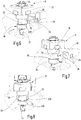
Figur 1 -
Figur 2Figur 1 -
Figur 3 die Revolverscheibe nachFigur 2Figur 2 -
Figur 4 die Revolverscheibe nach denFiguren 2, 3 -
Figur 5Figur 4 in einer anderen perspektivischen Darstellung, -
Figur 6 bis 9Figur 4 mit zugeordnetem Spannelement unter Veranschaulichung unterschiedlicher Stellungen des Spannelements bezüglich des Werkzeughalters, jeweils in perspektivischer Darstellung, -
Figur 10Figur 9 -
Figur 11Figur 10 -
Figur 12Figur 11entsprechend Figur 5 , -
Figur 13Figur 4 in einer abgewandelten Ausführungsform und in perspektivischer Darstellung, -
Figur 14Figur 13 -
Figur 15Figur 13 -
Figur 16Figur 15 -
Figur 17Figur 4/5 bestückt mit einem Werkzeughalter nachFigur 13 -
Figur 18Figur 17
-
Figure 1 a machine tool in the form of a lathe according to the invention, in a simplified schematic perspective illustration, -
Figure 2 the turret disk of the tool turret of the machine toolFigure 1 , in a top view of the back, -
Figure 3 the revolver diskFigure 2 in a side view, partially cut along the line III-III ofFigure 2 , -
Figure 4 the revolver disk after theFigures 2, 3 equipped with two tool holders, in a perspective view with a view of the rear, -
Figure 5 the arrangement according toFigure 4 in another perspective view, -
Figures 6 to 9 a tool holder according to the arrangementFigure 4 with assigned clamping element, showing different positions of the clamping element with respect to the tool holder, each in a perspective view, -
Figure 10 the arrangement according toFigure 9 , in a plan view, -
Figure 11 the revolver diskFigure 10 in a modified embodiment with an additional locking ring in a perspective view corresponding to Figure 4, -
Figure 12 the arrangement according toFigure 11 , in another perspective illustration accordinglyFigure 5 , -
Figure 13 a tool holder according to the arrangementFigure 4 in a modified embodiment and in a perspective view, -
Figure 14 the tool holderFigure 13 with the ring-shaped clamping part removed, in a perspective view, -
Figure 15 the ring-shaped clamping part of the tool holder afterFigure 13 , in a view from below and in a perspective representation, -
Figure 16 the annular clamping part afterFigure 15 , in a top view and a perspective illustration, -
Figure 17 the revolver diskFigure 4/5 equipped with a tool holderFigure 13 , in axial section in a perspective partial representation and -
Figure 18 the arrangement according toFigure 17 in another perspective partial illustration.
Die in
Jede der Aufnahmen 8 der polygonen Revolverscheibe 7 ist mit einer ebenen Auflagefläche 10 (
Mittels eines auf ihrer Rückseite vorragend angeordneten Flansches 14 ist die Revolverscheibe in einem ihre Antriebseinrichtungen enthaltende Gehäuse 15 des Werkzeugrevolvers 3 um ihre Achse 16 drehbar gelagert. In an sich bekannter Weise kann die Revolverscheibe 7 von ihrer Antriebseinrichtung taktweise um ihre Drehachse 16 derart verdreht werden, dass jeweils wenigstens einer der Werkzeughalter 9 in einer Bearbeitungsstellung steht, in der das in ihm vorgesehene Werkzeug auf das Werkstück einwirkt.By means of a
Von den unterschiedlichen Werkstückhaltern 9 ist eine Bauart beispielhaft in den
Zur Befestigung des Werkzeughalters 9 an der Revolverscheibe 7 ist der Schaft 19 als ein rechtwinklig zu der Auflagefläche 18 verlaufender Zuganker ausgebildet, der mit einer an der Revolverscheibe 7 vorgesehenen Spannvorrichtung zusammenwirkt. Diese Spannvorrichtung weist ein an der Revolverscheibe 7 quer zu dem Schaft 19 zwischen einer Spannstellung und einer Freigabestellung verstellbar gelagertes Spannelement in Gestalt eines Schiebers 22 auf, der in einer der jeweiligen Aufnahme 8 zugeordneten Längsführung 23 verschieblich geführt ist (
Der Schieber 22 ist im Querschnitt rechteckig und im Wesentlichen plattenförmig mit zueinander parallelen einander gegenüberliegenden breitseitigen Flächen 24, 25 ausgebildet, von denen die der Drehachse 16 der Revolverscheibe 7 zugewandte untere Fläche 24 als erste Spannfläche bezeichnet wird. Jede der Längsführungen 23 ist mit einer parallelflächig begrenzten schlitzartigen Öffnung 26 versehen, die von der dem Lagerflansch 14 zu gewandten Rückseite der Revolverscheibe 7 aus sich bis in die Aufnahmebohrung 11 erstreckt und die so bemessen ist, dass sie den jeweiligen Schieber 22 im Schiebesitz aufnimmt. Die obere Begrenzungswand 230 der schlitzartigen Öffnung 26 ist in ihrer Lage bezüglich der Auflagefläche 10 der zugeordneten Aufnahme 8 eng toleriert. Der Schieber 22 ist an seiner der Revolverscheibe 7 zugewandten vorderen Stirnseite mit einer etwa halbkreisförmigen Ausnehmung 28 versehen, sodass er insgesamt eine etwa gabelförmige Gestalt aufweist. Er ist auf seiner der Ausnehmung 28 gegenüberliegenden Seite mit einem außerhalb der Revolverscheibe 7 liegenden ersten Kupplungselement 29 verbunden, das in Gestalt eines sich zum Umfang der Revolverscheibe 7 hin öffnenden Hakens ausgebildet ist, wie dies beispielsweise den
Mit dem ersten Kupplungselement 29 kann ein zweites Kupplungselement 30 in Eingriff gebracht werden, das über eine Betätigungsstange 31 mit einer Stellvorrichtung 32 gekuppelt ist, die dazu eingerichtet ist, den Schieber 22 über die Kupplungselemente 29, 30 in seiner Längsführung 23 zwischen einer Spannstellung und einer Freigabestellung hin und her zu verstellen. Die Stellvorrichtung 32 kann beispielsweise einen Hydraulikzylinder oder ein anderes mechanisches oder elektromechanisches Antriebselement enthalten, das von außen wahlweise ansteuerbar ist und es erlaubt, der Betätigungsstange 31 die erwähnte hin- und hergehende lineare Bewegung zu erteilen. Die Hakenform der komplementären Kupplungselemente 29, 30 ist so konfiguriert, dass die beiden Kupplungselemente 29, 30 bezogen auf
Der Schaft 19 des Werkzeughalters 9 ist in Achsrichtung begrenzt elastisch dehnbar ausgebildet. Zu diesem Zwecke ist bei dem dargestellten Ausführungsbeispiel der Schaft 19 mit einem Bereich verringerten Durchmessers gestaltet, der ein Dehnelement 33 bildet. Alternativ könnte die elastische Dehnfähigkeit des Schaftes 19 auch durch andere Maßnahmen erreicht werden, beispielsweise durch eine entsprechend geringe Wandstärke oder zweckentsprechende Einschnitte oder vergleichbare Elemente, die die erforderliche Dehnfähigkeit ergeben.The
Das Dehnelement 33 ist auf der dem Werkzeughalter 9 abgewandten Seite durch eine Ringschulter 34 begrenzt, die eine rechtwinklig zu der Achse des Schaftes 19 verlaufende zweite Spannfläche 35 bildet. Diese zweite Spannfläche 35 ist derart positioniert, dass bei in die Aufnahme 8 eingesetztem Werkzeughalter 9 die auf der Unterseite des zugeordneten Schiebers 22 befindliche erste Spannfläche 24 um ein geringes vorbestimmtes Maß unterhalb der zweiten Spannfläche 35 des Schaftes 19 liegt, derart, dass bei übereinander geschobenen Spannflächen 24, 35 über den in der Längsführung 23, bezogen auf die Revolverscheibe 7, radial abgestützten Schieber 22 der Schaft 19 im Bereiche seines Dehnelements 33 axial elastisch in dem Maße gedehnt wird, dass die für ein sicheres Aufpressen der Auflagefläche 18 des Werkzeughalters 9 auf die Auflagefläche 10 der Revolverscheibe 7 erforderliche vorbestimmte Spannkraft erzeugt wird. Der gedehnte Schaft 19 wirkt dabei als ein an dem Gehäuse 17 des Werkzeughalters 9 zentral angreifender Zuganker.The
An der Außenkante der ersten Spannfläche 24 des Schiebers 22 und/oder der zweiten Spannfläche 35 des Schaftes 19 ist jeweils eine Auflaufschräge 330 bzw. 340 vorgesehen, die das Aufschieben des Schiebers 22 auf die zweite Spannfläche 35 an dem Schaft 19 erleichtert.On the outer edge of the
Die etwa halbkreisförmige Ausnehmung 28 an dem Schieber 22 weist eine Gabelweite auf, die mit radialem Spiel dem Durchmesser des Dehnelements 33 des Schaftes 19 entspricht, sodass bei in der Spannstellung stehendem Schieber 22 eine satte Auflage seiner ersten Spannfläche 24 auf der zweiten Spannfläche 35 des Schaftes 19 gewährleistet ist. Die erste Spannfläche 24 ragt darum in der Regel über die Mittelachse des zylindrischen Dehnelementes 33 radial hinaus.The approximately
Die Funktionsweise der beschriebenen Spannvorrichtung ist wie folgt:
Ausgehend von dem in einer zurückgezogenen Freigabestellung stehenden Schieber 22 entsprechend
Proceeding from the
Anschließend wird durch eine entsprechende Ansteuerung die Stellvorrichtung 32 veranlasst, den Schieber 22 gegen den Schaft 19 vorzuschieben derart, dass über die Auflaufschrägen 330/340 die erste Spannfläche 24 des Schiebers 22 auf die zweite Spannfläche 35 des Schaftes 19 aufgeschoben und dabei der Schaft 19 radial nach innen gezogen wird, sodass über das Dehnelement 33 die erforderliche axiale Spannkraft erzeugt wird, mit der der Werkzeughalter 9 auf die Revolverscheibe 7 aufgepresst wird. Die Situation beim Auflaufen des Schiebers 22 auf die zweite Spannfläche 35 ist in
Der Schieber 22 wird nach dem Auflaufen seiner ersten Spannfläche 24 auf die zweite Spannfläche 35 des Schaftes 19 in die in
Da die beiden Spannflächen 24, 35 in parallelen Ebenen liegen ist der Schieber 22 in seiner eingeschobenen Spannstellung entsprechend
Bei dem dargestellten Ausführungsbeispiel sind die erste und die zweite Spannfläche 24 bzw. 35 wie erwähnt parallel zueinander ausgerichtet. Es sind auch Ausführungsformen denkbar, bei denen diese Flächen einen kleinen Winkel miteinander einschließen, um beispielsweise eine Nachstellung der Schieber 22 bezüglich des jeweiligen Schaftes 19 zu ermögliche, wie sie beispielsweise zum Ausgleich von Verschleiß oder Fertigungstoleranzen zweckmäßig sein kann. Die hakenförmigen Kupplungselemente 29, 30 haben dafür ein ausreichend großes Spiel ihrer Hakenöffnungen. In jedem Fall muss aber die selbsthemmende gegenseitige Eingriffnahme der Spannflächen gewährleistet bleiben.In the illustrated embodiment, the first and the
Die Schieber 22 werden bei dem dargestellten Ausführungsbeispiel von der Rückseite der Revolverscheibe 7 her betätigt. Grundsätzlich sind auch Ausführungsformen denkbar, bei denen die Schieber von der Vorderseite der Revolverscheibe aus zur Betätigung zugänglich sind. Auch muss die zweite Spannfläche 35 nicht unbedingt durch eine Ringschulter des Schaftes 19 gebildet sein. Es sind auch andere Ausbildungen etwa in Form von Nuten, Absätzen und dergleichen denkbar. In jedem Fall wirkt der Schaft 19 als Zuganker, der zentral an dem Werkzeughalter angreift, wobei gewährleistet ist, dass dieser durch die Einwirkung der Spannkraft und die Betätigung der Spannelemente nicht verformt wird und die Spannkraft rechtwinklig zu den Auflageflächen 10, 18 wirkt.In the embodiment shown, the
Die neue Werkzeugmaschine mit ihrem beschriebenen Werkzeugträger und ihrem Werkzeughaltern ist insbesondere für den automatischen Werkzeugwechsel eingerichtet. Dazu ist vom Hersteller der Maschine eine bestimmte Werkzeugwechselposition der Revolverscheibe 7 festgelegt. In dieser Werkzeughalter-Wechselposition der Revolverscheibe 7 soll der jeweils auszuwechselnde Werkzeughalter gut zugänglich sein um einen problemlosen Werkzeughalterwechsel zu gewährleisten, während ein anderer in der Bearbeitungsposition stehender Werkzeughalter mit seinem Werkzeug einen Bearbeitungsvorgang vornimmt. Die Werkzeughalter-Wechselposition und die Bearbeitungsposition stehen in keinem direkten Zusammenhang. Es muss nur sichergestellt sein, dass die Spannvorrichtung des auszuwechselnden Werkzeughalters durch einen Maschinenbediener oder ein entsprechendes Handhabungssystem unbehindert betätigt werden kann.The new machine tool with its described tool carrier and its tool holder is set up in particular for automatic tool changes. For this purpose, a specific tool change position of the
Zum Wechseln eines Werkzeughalters 9 fährt die Revolverscheibe 7 in ihre Werkzeughalterwechselposition, in der die Stellvorrichtung 32 angeordnet ist. Dabei kommen die Kupplungselemente 29, 30 des Schiebers 22 des auszuwechselnden Werkzeughalters 9 miteinander in Eingriff. Nunmehr wird entweder von der Steuerung der Werkzeugmaschine aus oder von dem Maschinenbediener die Stellvorrichtung 32 betätigt. Diese zieht über die Betätigungsstange 31 und die Kupplung 29/30 den Schieber 22 aus der Revolverscheibe 7 so weit heraus, dass er in die Freigabestellung nach
Wie bereits erwähnt, ist die Antriebsart der Stellvorrichtung 32 zweckentsprechend zu wählen. Es muss lediglich eine mechanische Wirkverbindung zu dem Schieber 22 vorhanden sein. Diese Verbindung kann, wie dargestellt, direkt über ein Gestänge erfolgen, sie kann aber auch über eine oder mehrere Umlenkungen geschehen. Es muss lediglich die Linearbewegung des Schiebers zum Spannen des Werkzeughalters erreicht werden. Anstelle des bereits erwähnten Hydraulikzylinders kann auch beispielsweise ein Gewindestange eingesetzt werden, um eine Drehbewegung eines Motors in eine Linearbewegung umzuwandeln.As already mentioned, the type of drive of the adjusting
Da die Stellvorrichtung 32 fest in der Werkzeugmaschine verbaut ist, erfolgt ihre Ansteuerung zweckmäßigerweise über die Werkzeugmaschine selbst. Dadurch kann sichergestellt werden, dass der Werkzeughalterwechsel nicht zur Unzeit eingeleitet wird. Die Einleitung des Werkzeughalterwechsels kann entweder vom Maschinenbediener oder über die Maschinensteuerung erfolgen, indem der Maschinenbediener einen entsprechenden Befehl an die Steuerung gibt. Der Werkzeughalterwechsel kann auch durch ein Handhabungssystem der Maschine vollautomatisch erfolgen, wobei die Steuerung des Handhabungssystems mit der Steuerung der Werkzeugmaschine gekoppelt ist um den Werkzeughalterwechsel zu steuern.Since the
Die Spannkraft mit der der Werkzeughalter 9 auf der Revolverscheibe 7 gespannt ist, wird durch die elastische Verformung des Schaftes 19 erzeugt. Es sind aber grundsätzlich auch Ausführungsformen denkbar, bei denen einem Werkzeughalter mehrere axial elastisch verformbare Zuganker zugeordnet sind, die mit grundsätzlich in der beschriebenen Weise zugeordneten Spannelementen zusammenwirken und an die Stelle des Schaftes 19 treten oder zusätzlich zu diesem vorhanden sind.The clamping force with which the
Der Schaft 16 ist mit einem gewissen radialen Spiel in seiner Aufnahmebohrung 11 der Revolverscheibe 7 aufgenommen. Dadurch ist vermieden, dass die exakte Positionierung des Werkzeughalters 9 auf der zugeordneten Aufnahmefläche 10 der Werkzeugscheibe 7, die durch das Zusammenwirken der Stellelemente 13 mit den Aufnahmenuten 12 gewährleistet ist, durch den in eine enge Aufnahmebohrung eingezwängten Schaft beeinträchtigt werden kann. Insbesondere bei kleinem Schaftdurchmesser kann es deshalb zweckmäßig sein, auf der dem Schieber gegenüberliegenden Seite in der Aufnahmebohrung 11 ein Widerlager für den Schieber vorzusehen, um zu vermeiden, dass der Schaft beim Einfahren des Schiebers 22 seitlich ausgelenkt wird. Ein solches Widerlager kann etwa durch ein in
Wie bereits erläutert, sind die Schieber 22 reibschlüssig in ihrer Spannstellung gehalten, ohne dass es dazu der Einwirkung der Stellvorrichtung 32 bedürfte. Beispielsweise bei Bearbeitungsvorgängen, die starke Vibrationen erzeugen, etwa bei Fräsarbeiten mit unterbrochenem Schnitt kann es zweckmäßig sein, zusätzliche Sicherungsmaßnahmen vorzusehen, die ein unbeabsichtigtes Lösen der in der Spannstellung stehenden Schieber 22 verhindern. Solche Sicherungsmittel sind in den
Diese Figuren zeigen die Revolverscheibe 7 in perspektivischen Ansichten, die der Darstellung nach den
Die Sicherungsmittel weisen einen im Querschnitt rechteckigen Ring 37 auf, der auf der Rückseite der Revolverscheibe 7 ortsfest an dem Gehäuse 15 des Werkzeugrevolvers 3 (
Nach Abschluss eines Werkzeughalter-Wechselvorgangs ist der entsprechende Schieber entsprechend
Die Erfindung wurde anhand eines Werkzeugträgers in Gestalt eines Sternrevolvers 3 beispielhaft erläutert. Sie ist aber auch für anders gestaltete Werkzeugrevolver geeignet und kann auch für Werkzeugträger eingesetzt werden, die eine lineare Bewegung ausführen, um ihre Werkzeuge in die jeweilige Bearbeitungsposition beziehungsweise in die Werkzeughalter-Wechselposition zu bringen.The invention was explained using a tool carrier in the form of a star turret 3 by way of example. However, it is also suitable for differently designed tool turrets and can also be used for tool carriers that perform a linear movement in order to bring their tools into the respective machining position or the tool holder change position.
Wie anhand der beschriebenen Ausführungsbeispiele der Revolverscheibe 7 und der Werkzeughalter 9 erläutert, gleitet bei einem Spannvorgang eines Werkzeughalters 9 der zugeordnete Schieber 22 mit seiner ersten Spannfläche 24 über die zweite Spannfläche 35 an dem einen Zuganker bildenden Schaft 19 des Werkzeughalters 9. Der Schieber 22 ist dabei über seine der Spannfläche 24 gegenüberliegende breitseitige Fläche 25 an der oberen Begrenzungswand 230 der schlitzartigen Öffnung 26 der Längsführung 23 abgestützt, sodass er die zum lagerichtigen Spannen des Werkzeughalters 9 erforderliche, verhältnismäßig große Spannkraft auf den als Zuganker wirkenden Schaft 19 übertragen kann. Dies bedeutet, dass die miteinander zusammenwirkenden Spannflächen 24, 35 und 25, 230 so gestaltet und mit solchen Materialpaarungen ausgebildet sein müssen, dass die Funktionsweise auch bei längeren Betriebszeiträumen der Werkzeugmaschine nicht durch Verschleißerscheinungen an diesen Flächen beeinträchtigt wird. Die Flächen 24, 25, 35 und 230 können deshalb beispielsweise, gegebenenfalls einzeln oder paarweise, mit einer geeigneten Beschichtung vorzugsweise aus Hartstoffen (zum Beispiel TiC, TiN, etc.) versehen sein. Möglich ist es auch, an dem Schieber 22 oder der ihn aufnehmenden schlitzartigen Öffnung 26 der Längsführung 23 aus einem verschleißfesten Material bestehende oder mit einem solchen Material beschichtete Einsätze vorzusehen, die die Oberflächen 24, 25, 230 und 35 tragen.As explained on the basis of the described embodiments of the
In den
Der Werkezughalter 9 entspricht in seinem grundsätzlichen Aufbau dem anhand der
Während bei der Ausführungsform des Werkzeughalters 9 nach den
Um das ringförmige Spannteil 40 auf dem Schaft 19 verdrehsicher zu halten, ist an dem Schaft 19 an der Ringschulter 34 ein Ringflansch 43 ausgebildet, der an seinem Umfang eine Ringnut 44 trägt, in die eine ringförmige Schulter 45 des Spannteils 40 eingreifen kann, sodass das Spannteil 40 im aufgeschobenen Zustand axial unverschieblich auf dem Schaft gehalten ist. Außerdem ist an der Umfangsfläche des Ringflansches 43 wenigstens eine Abflachung 440 vorhanden, der eine entsprechende Abflachung auf der Innenseite des Spannteils 40 zugeordnet ist und die eine Verdrehsicherung des auf den Schaft 19 aufgeschobenen Spannteils 40 bewirkt. Der Abflachung 440 kann beispielsweise auf der diametral gegenüberliegenden Seite des Schaftes eine zweite entsprechende Abflachung zugeordnet sein, wie es denkbar ist, auch mehrere solche Abflachungen 440 um den Umfang des Ringflansches 43 verteilt vorzusehen, um damit den Werkzeughalter 9 wahlweise in mehreren Drehstellungen eines Schaftes auf der Revolverschiebe 7 spannen zu können.In order to hold the
Im Bereiche der Abflachung 440 ist eine radiale Gewindebohrung 45 vorhanden, mit der im aufgesetzten Zustand des Spannteils 40 eine an diesem vorgesehene randoffene Ausnehmung 46 fluchtet. In die Gewindebohrung 45 kann eine in
Vor dem Einsetzen des Werkzeughalters 9 in die Revolverscheibe 7 wird ausgehend von dem Zustand nach
Das ring- oder hufeisenförmige Spannteil 40 kann einfach ausgetauscht werden, wenn Verschleißerscheinungen dies als zweckmäßig erscheinen lassen. Außerdem können mit Spannteilen 40 verschiedener axialer Dicke, durch entsprechende Einstellung des Abstandes zwischen den Flächen 41, 351, die beim Spannvorgang auftretende Spannkraft den jeweiligen Erfordernissen angepasst oder eine Herstellungstoleranz ausgeglichen werden. Wie beispielsweise den
Das Spannteil 40 kann auch mehrteilig ausgebildet sein, wie auch Ausführungsformen des Werkzeughalters denkbar sind, bei denen auf den Ringflansch 43 verzichtet oder dieser beispielsweise durch Nuten oder dergleichen an dem Schaft 19 ersetzt ist.The clamping
Claims (32)
wobei die Einrichtungen zur Befestigung des Werkzeughalters wenigstens einen rechtwinklig zu der Auflagefläche des Werkzeughalters oder des Werkzeugträgers verlaufend zugeordneten Zuganker (19) aufweisen und dem Werkzeughalter und/oder dem Werkzeugträger eine Spannvorrichtung zugeordnet ist, die bei in die Aufnahme eingesetztem Werkzeughalter bei einem Spannvorgang an dem jeweiligen Zuganker angreifend und auf diesen eine axiale Spannkraft ausübend ausgebildet ist, mit der die Auflageflächen des Werkzeughalters und des Werkzeugträgers aufeinander gepresst sind, dadurch gekennzeichnet, dass
die Spannvorrichtung wenigstens ein an dem Werkzeugträger quer zu dem Zuganker zwischen einer Spannstellung und einer Freigabestellung verstellbar gelagertes Spannelement (22) aufweist, das eine erste Spannfläche (24) trägt,
an dem Zuganker eine zweite Spannfläche (35) vorgesehen ist, mit der die erste Spannfläche (24) des Spannelements (22) in der Spannstellung selbsthemmend in Eingriff steht, der Zuganker in Achsrichtung begrenzt elastisch verformbar ist und bei in der Spannstellung stehendem Spannelement über die miteinander in Eingriff stehenden Spannflächen in einem die erforderliche axiale Spannkraft erzeugende Maße gedehnt ist und
das Spannelement über eine Abhängigkeit von der Bewegung des Werkzeugträgers ansteuerbare Kupplung (29, 30) mit einer dem Werkzeugträger zugeordneten Stellvorrichtung (32) kuppelbar ist, durch die es zwischen seiner Spannstellung und seiner Freigabestellung verstellbar ist.Machine tool with a movable tool carrier (7) which is set up to be equipped with tool holders and has the receptacles (8) for tool holders (9), each tool holder and the tool holder having mutually associated support surfaces (10, 18) and devices for fastening the tool holder to the tool holder and Adjusting means (12, 13) are provided for the precise positioning of the tool holder with respect to its seat assigned to it, and
wherein the devices for fastening the tool holder have at least one tie rod (19) assigned at right angles to the support surface of the tool holder or the tool carrier, and a clamping device is assigned to the tool holder and / or the tool carrier, which when the tool holder is inserted into the receptacle during a clamping process on the attacking the respective tie rod and exerting an axial clamping force thereon, with which the bearing surfaces of the tool holder and the tool carrier are pressed onto one another, characterized in that
the clamping device has at least one clamping element (22) which is mounted on the tool carrier transversely to the tie rod between a clamping position and a release position and carries a first clamping surface (24),
a second clamping surface (35) is provided on the tie rod, with which the first clamping surface (24) of the clamping element (22) engages in a self-locking manner in the clamping position, the tie rod is elastically deformable to a limited extent in the axial direction and, when the tensioning element is in the tensioning position, is stretched over the engaging tensioning surfaces to an extent that generates the required axial tensioning force and
the clamping element can be coupled via a coupling (29, 30) that is controllable as a function of the movement of the tool carrier to an adjusting device (32) assigned to the tool carrier, by means of which it can be adjusted between its clamping position and its release position.
dadurch gekennzeichnet, dass der Werkzeugträger (7) für jede seiner Aufnahmen (8)eine Längsführung (23) aufweist, in der ein als Schieber ausgebildetes Spannelement (22) der Spannvorrichtung zwischen einer Spannstellung und einer Freigabestellung für einen auf die Auflagefläche aufgesetzten Werkzeughalter beweglich gelagert ist, das an einem in der Spannstellung in die Aufnahmebohrung (11) ragenden Endteil eine erste Spannfläche (24) trägt, die zum selbsthemmenden Zusammenwirken mit einer zugeordneten zweiten Spannfläche (35) an dem aufgesetzten Werkzeughalter konfiguriert ist und dass das Spannelement (22) über eine in Abhängigkeit von der Bewegung des Werkzeugträgers selbsttätig einund auskuppelbare Kupplung, mit einer dem Werkzeugträger zugeordneten und an einer Werkzeughalterwechselstation angeordneten Stellvorrichtung (32) kuppelbar ist.Tool carrier, in particular for a machine tool according to one of the preceding claims, which has receptacles (8) for tool holders (9), each tool holder having a support surface (16) and devices for fastening the tool holder and adjusting means (13) for precisely positioning the tool holder with respect to it Has associated receptacle and the tool carrier in the area of its respective receptacle has at least one receiving bore (11) running at right angles to its support surface (10), which is designed to receive a tie rod of an attached tool holder and wherein the tool carrier has a clamping device for a mounted on the receptacle Tool holder is assigned,
characterized in that the tool carrier (7) has a longitudinal guide (23) for each of its receptacles (8), in which a clamping element (22), designed as a slide, of the clamping device is movably mounted between a clamping position and a release position for a tool holder placed on the support surface which carries a first clamping surface (24) on an end part protruding into the receiving bore (11) in the clamping position, which is configured for self-locking interaction with an associated second clamping surface (35) on the attached tool holder and that the clamping element (22) over a coupling that can be automatically engaged and disengaged as a function of the movement of the tool carrier can be coupled to an adjusting device (32) assigned to the tool carrier and arranged at a tool holder changing station.
Priority Applications (4)
| Application Number | Priority Date | Filing Date | Title |
|---|---|---|---|
| JP2020127174A JP2021041523A (en) | 2019-07-30 | 2020-07-28 | Machine tool having movable tool carrier, tool carrier, and tool holder therefor |
| KR1020200093604A KR20210014585A (en) | 2019-07-30 | 2020-07-28 | Machine tool having a movable tool carrier, tool carrier and tool holder therefore |
| US16/942,510 US11583938B2 (en) | 2019-07-30 | 2020-07-29 | Machine tool having a movable tool carrier, tool carrier and tool holder therefor |
| US18/152,199 US11945035B2 (en) | 2019-07-30 | 2023-01-10 | Tool holder |
Applications Claiming Priority (1)
| Application Number | Priority Date | Filing Date | Title |
|---|---|---|---|
| DE102019120522.0A DE102019120522A1 (en) | 2019-07-30 | 2019-07-30 | Machine tool with a movable tool carrier, tool carrier and tool holder therefor |
Publications (1)
| Publication Number | Publication Date |
|---|---|
| EP3771510A1 true EP3771510A1 (en) | 2021-02-03 |
Family
ID=70802578
Family Applications (1)
| Application Number | Title | Priority Date | Filing Date |
|---|---|---|---|
| EP20175642.6A Pending EP3771510A1 (en) | 2019-07-30 | 2020-05-20 | Tool holder, machine tool with movable tool holder, and tool bracket for same |
Country Status (5)
| Country | Link |
|---|---|
| US (2) | US11583938B2 (en) |
| EP (1) | EP3771510A1 (en) |
| JP (1) | JP2021041523A (en) |
| KR (1) | KR20210014585A (en) |
| DE (1) | DE102019120522A1 (en) |
Cited By (1)
| Publication number | Priority date | Publication date | Assignee | Title |
|---|---|---|---|---|
| US20200215621A1 (en) * | 2019-01-08 | 2020-07-09 | Esa Eppinger Gmbh | Machine Tool |
Families Citing this family (1)
| Publication number | Priority date | Publication date | Assignee | Title |
|---|---|---|---|---|
| KR102507278B1 (en) * | 2021-11-17 | 2023-03-07 | 현대위아 주식회사 | Driven tool mounting device and method for driven tool mounting using the driven tool mounting device |
Citations (7)
| Publication number | Priority date | Publication date | Assignee | Title |
|---|---|---|---|---|
| US5873682A (en) * | 1997-04-14 | 1999-02-23 | Koyo Corporation Of Usa | Pivoting tool holder |
| DE19940330A1 (en) | 1999-08-25 | 2001-03-15 | Esa Eppinger Gmbh | Tool clamping device for rotary lathes has separately mounted adjustable setting elements set on tool holder and associated bearing positions on tool support to ensure accurate fit |
| DE102008048206A1 (en) | 2008-09-20 | 2010-04-01 | Sauter Feinmechanik Gmbh | Tool revolver, particularly for machine tools, comprises tool disk which rotates around revolving axis, where multiple tool stations are distributed along disk circumference, and blade of receiver is supported at seat face |
| EP2910325A1 (en) * | 2014-02-19 | 2015-08-26 | Ott-Jakob Spanntechnik GmbH | Tool revolver |
| DE102014119482A1 (en) | 2014-12-23 | 2016-06-23 | Esa Eppinger Gmbh | Tool clamping device |
| DE102017007905A1 (en) * | 2017-08-17 | 2019-02-21 | Oesterle + Partner GbR (vertretungsberechtigter Gesellschafter: Hermann Oesterle, 72202 Nagold, Harald Öschger, 79183 Waldkirch) | Locking device for machine tools |
| EP3698906A1 (en) * | 2019-02-25 | 2020-08-26 | Index-Werke GmbH & Co. KG Hahn & Tessky | Tool carrier and tool holder |
Family Cites Families (7)
| Publication number | Priority date | Publication date | Assignee | Title |
|---|---|---|---|---|
| DE2234676C2 (en) * | 1972-07-14 | 1975-02-27 | Gildemeister Ag, 4800 Bielefeld | Arrangement for changing tool holders equipped with tools on a machine tool |
| DD138520B1 (en) * | 1978-05-25 | 1980-07-23 | Volker Thomas | DEVICE FOR TOOL CHANGE FOR A TURNING MACHINE |
| US5127775A (en) * | 1991-11-01 | 1992-07-07 | Smith & Wesson Corp. | Fail safe stop for a drill press control device |
| KR970020283A (en) * | 1995-10-31 | 1997-05-28 | 유상부 | Abrasion resistant member with excellent wear resistance and manufacturing method thereof |
| JP4285527B2 (en) * | 2006-10-30 | 2009-06-24 | 三菱マテリアル株式会社 | Cutting head replaceable tool and method for fastening arbor to cutting head |
| EP3536429A1 (en) * | 2018-03-06 | 2019-09-11 | Daunert Maquinas Herramientas, S.A. | Kit to assist in the manual change of a tool from a rotary tool holder |
| DE102019100257A1 (en) * | 2019-01-08 | 2020-07-09 | Esa Eppinger Gmbh | Machine tool |
-
2019
- 2019-07-30 DE DE102019120522.0A patent/DE102019120522A1/en active Pending
-
2020
- 2020-05-20 EP EP20175642.6A patent/EP3771510A1/en active Pending
- 2020-07-28 KR KR1020200093604A patent/KR20210014585A/en unknown
- 2020-07-28 JP JP2020127174A patent/JP2021041523A/en active Pending
- 2020-07-29 US US16/942,510 patent/US11583938B2/en active Active
-
2023
- 2023-01-10 US US18/152,199 patent/US11945035B2/en active Active
Patent Citations (7)
| Publication number | Priority date | Publication date | Assignee | Title |
|---|---|---|---|---|
| US5873682A (en) * | 1997-04-14 | 1999-02-23 | Koyo Corporation Of Usa | Pivoting tool holder |
| DE19940330A1 (en) | 1999-08-25 | 2001-03-15 | Esa Eppinger Gmbh | Tool clamping device for rotary lathes has separately mounted adjustable setting elements set on tool holder and associated bearing positions on tool support to ensure accurate fit |
| DE102008048206A1 (en) | 2008-09-20 | 2010-04-01 | Sauter Feinmechanik Gmbh | Tool revolver, particularly for machine tools, comprises tool disk which rotates around revolving axis, where multiple tool stations are distributed along disk circumference, and blade of receiver is supported at seat face |
| EP2910325A1 (en) * | 2014-02-19 | 2015-08-26 | Ott-Jakob Spanntechnik GmbH | Tool revolver |
| DE102014119482A1 (en) | 2014-12-23 | 2016-06-23 | Esa Eppinger Gmbh | Tool clamping device |
| DE102017007905A1 (en) * | 2017-08-17 | 2019-02-21 | Oesterle + Partner GbR (vertretungsberechtigter Gesellschafter: Hermann Oesterle, 72202 Nagold, Harald Öschger, 79183 Waldkirch) | Locking device for machine tools |
| EP3698906A1 (en) * | 2019-02-25 | 2020-08-26 | Index-Werke GmbH & Co. KG Hahn & Tessky | Tool carrier and tool holder |
Cited By (2)
| Publication number | Priority date | Publication date | Assignee | Title |
|---|---|---|---|---|
| US20200215621A1 (en) * | 2019-01-08 | 2020-07-09 | Esa Eppinger Gmbh | Machine Tool |
| US11759903B2 (en) * | 2019-01-08 | 2023-09-19 | Esa Eppinger Gmbh | Machine tool |
Also Published As
| Publication number | Publication date |
|---|---|
| US20210031274A1 (en) | 2021-02-04 |
| JP2021041523A (en) | 2021-03-18 |
| DE102019120522A1 (en) | 2021-02-04 |
| US11583938B2 (en) | 2023-02-21 |
| KR20210014585A (en) | 2021-02-09 |
| US20230166337A1 (en) | 2023-06-01 |
| US11945035B2 (en) | 2024-04-02 |
Similar Documents
| Publication | Publication Date | Title |
|---|---|---|
| DE102014119482B4 (en) | Tool clamping device, tool holder and tool carrier | |
| DE102010043667A1 (en) | Machine tool with tool holder | |
| DE3441821A1 (en) | KNIFE HEAD | |
| EP3771510A1 (en) | Tool holder, machine tool with movable tool holder, and tool bracket for same | |
| DE8505616U1 (en) | Tool adapter for a spindle of drilling, milling and similar machine tools | |
| DE3010934C2 (en) | ||
| DE3209999A1 (en) | TOOL HEAD AND REPLACEMENT DEVICE ON MACHINE TOOLS | |
| EP0296460A1 (en) | Tool for circumferential machining of workpieces, particularly for boring | |
| EP2934796B1 (en) | Apparatus with an alignment device and an alignment method | |
| DE3913139C2 (en) | ||
| EP3509781B1 (en) | Multi-edged machining tool and method for machining a bearing race | |
| DE102019100257A1 (en) | Machine tool | |
| EP1884303B1 (en) | Method for centring workpieces and device for performing such a method | |
| DE2840129A1 (en) | FASTENING DEVICE FOR HOLDING A WORKPIECE ON A MACHINE TOOL | |
| EP1147838B1 (en) | Machine tool and chuck | |
| WO2018046035A1 (en) | Blade carrier and machining tool with a blade carrier | |
| EP3658319B1 (en) | Cutting tool and method for machining a bearing race | |
| EP2623257A1 (en) | Position compensation device in a machine tool | |
| EP4003643A1 (en) | Machine tool holder, method and computer program for operating a machine tool having such a machine tool holder | |
| DE3341252A1 (en) | Automatic tool changer | |
| EP0189528A1 (en) | Chuck for machine tools | |
| WO2019020783A1 (en) | Adjusting device for a cutting tool and cutting tool having an adjusting device | |
| EP3684533B1 (en) | Turning of workpieces on a machine tool | |
| DE102017115951A1 (en) | Tool changing device, machine tool with such a tool changing device and associated method | |
| EP0343337B1 (en) | Device for the detachable fastening of a work piece support to an adapter |
Legal Events
| Date | Code | Title | Description |
|---|---|---|---|
| PUAI | Public reference made under article 153(3) epc to a published international application that has entered the european phase |
Free format text: ORIGINAL CODE: 0009012 |
|
| STAA | Information on the status of an ep patent application or granted ep patent |
Free format text: STATUS: THE APPLICATION HAS BEEN PUBLISHED |
|
| AK | Designated contracting states |
Kind code of ref document: A1 Designated state(s): AL AT BE BG CH CY CZ DE DK EE ES FI FR GB GR HR HU IE IS IT LI LT LU LV MC MK MT NL NO PL PT RO RS SE SI SK SM TR |
|
| AX | Request for extension of the european patent |
Extension state: BA ME |
|
| STAA | Information on the status of an ep patent application or granted ep patent |
Free format text: STATUS: REQUEST FOR EXAMINATION WAS MADE |
|
| 17P | Request for examination filed |
Effective date: 20210223 |
|
| RBV | Designated contracting states (corrected) |
Designated state(s): AL AT BE BG CH CY CZ DE DK EE ES FI FR GB GR HR HU IE IS IT LI LT LU LV MC MK MT NL NO PL PT RO RS SE SI SK SM TR |
|
| RIN1 | Information on inventor provided before grant (corrected) |
Inventor name: JUDAS, JOEL Inventor name: LIEDECKE, ROLF |
|
| STAA | Information on the status of an ep patent application or granted ep patent |
Free format text: STATUS: EXAMINATION IS IN PROGRESS |
|
| 17Q | First examination report despatched |
Effective date: 20231020 |