EP3415783A1 - Bremsscheiben-/nabenverbindung - Google Patents
Bremsscheiben-/nabenverbindung Download PDFInfo
- Publication number
- EP3415783A1 EP3415783A1 EP18175528.1A EP18175528A EP3415783A1 EP 3415783 A1 EP3415783 A1 EP 3415783A1 EP 18175528 A EP18175528 A EP 18175528A EP 3415783 A1 EP3415783 A1 EP 3415783A1
- Authority
- EP
- European Patent Office
- Prior art keywords
- hub
- coupling
- connection according
- elements
- brake discs
- Prior art date
- Legal status (The legal status is an assumption and is not a legal conclusion. Google has not performed a legal analysis and makes no representation as to the accuracy of the status listed.)
- Granted
Links
Images



Classifications
-
- F—MECHANICAL ENGINEERING; LIGHTING; HEATING; WEAPONS; BLASTING
- F16—ENGINEERING ELEMENTS AND UNITS; GENERAL MEASURES FOR PRODUCING AND MAINTAINING EFFECTIVE FUNCTIONING OF MACHINES OR INSTALLATIONS; THERMAL INSULATION IN GENERAL
- F16D—COUPLINGS FOR TRANSMITTING ROTATION; CLUTCHES; BRAKES
- F16D65/00—Parts or details
- F16D65/02—Braking members; Mounting thereof
- F16D65/12—Discs; Drums for disc brakes
- F16D65/123—Discs; Drums for disc brakes comprising an annular disc secured to a hub member; Discs characterised by means for mounting
-
- F—MECHANICAL ENGINEERING; LIGHTING; HEATING; WEAPONS; BLASTING
- F16—ENGINEERING ELEMENTS AND UNITS; GENERAL MEASURES FOR PRODUCING AND MAINTAINING EFFECTIVE FUNCTIONING OF MACHINES OR INSTALLATIONS; THERMAL INSULATION IN GENERAL
- F16D—COUPLINGS FOR TRANSMITTING ROTATION; CLUTCHES; BRAKES
- F16D65/00—Parts or details
- F16D65/02—Braking members; Mounting thereof
- F16D2065/13—Parts or details of discs or drums
- F16D2065/1304—Structure
- F16D2065/1312—Structure circumferentially segmented
-
- F—MECHANICAL ENGINEERING; LIGHTING; HEATING; WEAPONS; BLASTING
- F16—ENGINEERING ELEMENTS AND UNITS; GENERAL MEASURES FOR PRODUCING AND MAINTAINING EFFECTIVE FUNCTIONING OF MACHINES OR INSTALLATIONS; THERMAL INSULATION IN GENERAL
- F16D—COUPLINGS FOR TRANSMITTING ROTATION; CLUTCHES; BRAKES
- F16D65/00—Parts or details
- F16D65/02—Braking members; Mounting thereof
- F16D2065/13—Parts or details of discs or drums
- F16D2065/134—Connection
- F16D2065/1384—Connection to wheel hub
-
- F—MECHANICAL ENGINEERING; LIGHTING; HEATING; WEAPONS; BLASTING
- F16—ENGINEERING ELEMENTS AND UNITS; GENERAL MEASURES FOR PRODUCING AND MAINTAINING EFFECTIVE FUNCTIONING OF MACHINES OR INSTALLATIONS; THERMAL INSULATION IN GENERAL
- F16D—COUPLINGS FOR TRANSMITTING ROTATION; CLUTCHES; BRAKES
- F16D65/00—Parts or details
- F16D65/02—Braking members; Mounting thereof
- F16D2065/13—Parts or details of discs or drums
- F16D2065/134—Connection
- F16D2065/1392—Connection elements
Definitions
- the present invention relates to a brake disk / hub connection according to the preamble of claim 1.
- the brake disc can be due to a Heat development during braking radially expand relative to the hub, which improves the heat dissipation resistance of the brake disc.
- Such a generic brake disc / hub connection is for example from the DE 199 18 069 A1 known.
- the brake disc / hub connection is exposed to different loads during a braking operation.
- a brake disc / hub connection is known in which the brake disc is fixed in the axial direction on one side by a rigid stop in the form of a retaining ring and on the other side by means of a resilient locking ring.
- the resilient locking ring is in this case fully encircling and is bolted to the hub.
- the stop serves to axially secure the brake disc to the hub.
- Object of the present invention is to provide a brake disc / hub connection, with a more uniform distribution of the braking torque on the driver of the hub and the support members of the brake disc can be achieved.
- the driver of the hub are coupled to one another via a coupling device which is dimensionally stable in the circumferential direction of the brake disk and is supported on the support elements of the brake disk.
- the coupling device is preferably attached to respective, a wheel flange of the hub facing away from end surfaces of the driver, in particular screwed.
- the coupling device is furthermore preferably located on respective end faces of the support elements of the brake disk facing away from the hub and thus secures the brake disk in its axial position on the hub.
- the coupling device is formed in a preferred embodiment as a coupling ring.
- This coupling ring can be designed in different design variants.
- the coupling ring preferably has a flat-ring-shaped body, with holes for carrying fastening bolts, with which the coupling ring attached to the drivers of the hub, in particular screwed.
- the fastening bolts are fastened to the drivers of the hub for axially securing the brake disk in the direction of the axis of rotation.
- the coupling ring according to a particularly preferred variant recesses, in which head ends of the fastening bolts can be accommodated.
- the coupling ring for additional stationary fixation on the hub recesses in which axially to the axis of rotation extending extensions of intermediate flanks of the driver and the support elements arranged intermediate elements are receivable.
- the radial width of the coupling ring can be formed continuously the same according to a further embodiment.
- the radial width of the coupling ring in a region which is supported on the drivers of the hub is greater than in a region which is supported on the support elements of the brake disk.
- the flat-ring-shaped base body In order to increase the rigidity of the flat-ring-shaped base body in order to increase the dimensional stability in the circumferential direction of the brake disk, the flat-ring-shaped base body preferably has a plurality of beads.
- a plurality of stiffening surfaces are integrally formed on an inner circumference of the flat-ring-shaped base body.
- a plurality of spring elements acting in the direction of the axis of rotation are formed on the flat-ring-shaped base body of the coupling ring.
- the coupling device has a plurality of coupling elements, wherein each of the coupling elements couples at least two of the drivers of the hub to each other.
- the coupling elements preferably at spaced-apart ends holes for the implementation of fastening bolts, provided that the coupling elements each couple two drivers of the hub with each other.
- the coupling elements are designed such that three or more drivers of the hub are coupled to one another by such a coupling element, corresponding bores are provided in the distances of the drivers of the hub from mutually corresponding positions of the coupling elements.
- the coupling elements form a coupling ring in the mounted on the drivers of the hub state, so that the ends of two such coupling elements are overlapping each other on each of the drivers.
- these spring elements acting in the direction of the axis of rotation have, as already mentioned above, to allow a play in the axial fixing of the brake disc to the hub.
- each of the coupling elements has an offset extending radially in the mounted state to the axis of rotation.
- the coupling device is designed as a coupling ring composed of a plurality of coupling elements, wherein each of the coupling elements is attached to one of the drivers of the hub.
- the ends of the coupling elements are connected in accordance with a variant cohesively together, in particular welded together.
- the ends of the coupling elements are designed as form-fitting connectable joint connection sections.
- the coupling device in the form of a coupling ring or individual coupling elements are preferably designed as cast components, forged components, sintered components or as stamped components.
- top, bottom, left, right, front, back, etc. refer exclusively to the exemplary representation and position of the brake disk / hub connection, the hub, the brake disk, the driver, the support elements selected in the respective figures , the coupling ring, the coupling elements and the like. These terms are not meant to be limiting, that is to say, by different working positions or the mirror-symmetrical design or the like, these references may change.
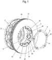
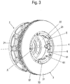
- FIG. 1 . 3 . 7 and 9 a respective brake disc / hub connection is shown, in which an annular, internally ventilated brake disc 3 with two spaced apart by webs friction rings 31, 32 is arranged on a hub 2.
- the brake disc 3 is placed axially to a common axis of rotation of the hub 2 and the brake disc 3 on the hub 2.
- the hub 2 For transmitting rotational or braking torque during braking operations, the hub 2 in the axial direction to the rotation axis A of a wheel flange 21 of the hub 2 extending driver 23, which is arranged between the inner circumference of the brake disc 3, extending in the direction of the axis of rotation A.
- Support elements 33 engage tooth-like.
- the drivers 23 extend axially to the axis of rotation A of a pot-shaped or hollow cylindrical portion 22 of the hub 2, which extends axially from the wheel flange 21 of the hub 2.
- intermediate elements 6 engage around the drivers 23 radially outward and in the circumferential direction and lie on the opposite flanks whose surface is preferably aligned radially to the axis of rotation A, flat.
- the axial fixation of the brake disc 3 takes place on the side facing the wheel flange 21 of the brake disc 3 by itself from the cup-shaped portion 22 of the hub 2, the driver 23 in the circumferential direction adjacent Aufschiebeanelle 26 against which the brake disc 3 in the mounted state axially to the axis of rotation A. becomes.
- a coupling device 4 formed here as a coupling ring.
- This coupling ring 4 couples the driver 23 of the hub 2 and is supported on the support members 33 of the brake disc 3 from.
- the coupling of the coupling ring 4 with the drivers 23 of the five drivers 23 of the hub 2 in this embodiment takes place here via fastening bolts 5 designed as bolts.
- the fastening bolts 5 consist of a bolt head 51 and a bolt neck with a subsequent to the bolt head 51 insertion portion 52 and a threaded threaded piece 53 which are screwed into corresponding threaded holes 25 in the end faces 24 of the driver 23.
- the coupling ring 4 is placed on the end faces 24 of the driver 23 and the end faces 34 of the support elements 33. Subsequently, the bolts 5 are performed by holes 43 in the coupling ring 4 and screwed into the threaded holes 25 in the end faces 24 of the driver 23.
- the radial width of the coupling ring 4 in a region 42 supported on the drivers 23 of the hub 2 is greater than in a region which is supported on the support elements 33 of the brake disk 3.
- the coupling ring 4 according to Fig. 2 Further, the bores 43 for receiving the bolts 5 adjacent recesses 44, in which axially to the axis of rotation A extending extensions 61 of the intermediate flanks 6 between the lateral flanks of the driver 23 and the support members 33 of the brake disc 3 are receivable.
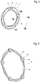
- the holes 73 surrounding recesses 72 are formed in the main body 71 of the coupling ring 7 for receiving the bolt head 51.
- the radial width of the coupling ring 7 is constant over the entire coupling ring 7.
- the radial width of the coupling ring 7 is significantly larger than the axial width of the coupling ring. 7
- beads 74 are introduced into the main body 71 of the coupling ring 7 in this embodiment variant.
- beads 74 are formed in the embodiment shown here in a circular segment in the spaces between adjacent recesses 72 for receiving the bolt heads 51 of the bolt 5 and introduced from the support members 33 of the brake disc 3 side facing away from the main body 71 of the coupling ring 7 as wells.
- the coupling ring 8 formed as a coupling device are also the holes 83 surrounding recesses 82 for receiving the bolt heads 51 of the bolt 5 is formed.
- the bolt 5 receiving portion of the coupling ring 8 is cylindrical here.
- the cylindrical parts of these interconnecting parts of the base body 81 are reinforced by integrally formed on an inner periphery of the flat-ring-shaped base body 81 of the coupling ring 8 stiffening surfaces 84 to increase the rigidity of the coupling ring 8.
- the stiffening surfaces 84 are formed in this embodiment, a circular segment-shaped, with straight inner edges with which the respective arc sections between the bolts 5 receiving recesses 82 are stiffened.
- FIG. 6 shown embodiment variant of the coupling ring 10 are in turn, adjacent to the holes 102 in the main body 101 of the coupling ring 10, recesses 103 for receiving the extensions 61 of the intermediate elements 6 introduced.
- the radial width of this coupling ring 10 is constant in this coupling ring 10.
- These spring elements 104 are formed here as tongues punched out of the base body 101, which are bent out of the plane of the flat-ring-shaped main body 101 of the coupling ring 10.
- the coupling device comprises a plurality of coupling elements 91, in which each of the coupling elements 91 couples at least two of the drivers 23 of the hub 2 to one another.
- the coupling elements 91 are mounted in the embodiment shown here so that together they form a coupling ring 9.
- Each of the coupling elements 91 has for this purpose respective bores 93, which are preferably introduced into the respective ends of the main body 92 of the coupling element 91. In the assembled state, the ends of two such coupling elements 91 overlap, so that each of the bolts 5 are screwed through the holes 93 of two such coupling elements 91 in the threaded holes of the driver 23 of the hub 2 are screwed.
- Each of the coupling elements 91 preferably has spring elements 94 acting in the direction of the axis of rotation A, wherein at least part of these spring elements 94 are supported on the support elements 33 of the brake disk 3 in the mounted state.
- each of the coupling elements 91 preferably has an offset 95 extending radially in the installed state relative to the axis of rotation A.
- the coupling device again consists of several coupling elements 111, in which each of the coupling elements 111 is fastened to one of the drivers 23 of the hub 2, in particular screwed to a respective bolt 5.
- the coupling elements 111 are at their ends 115, 116 fixed to each other so that together they form a coupling ring 11.
- Each of the coupling elements 11 has a bore 113 which is introduced into a mounted in the mounted state on an end face 24 of the driver 23 intermediate level 117.
- This intermediate plane 117 is arranged between arcuate segments acting as spring elements 114.
- At the arc-shaped segments acting as spring elements 114 are adjoined by outer planes 118 of the base body 112 of the coupling element 111, which rest in the mounted state on respective support elements 33 of the brake disk 3.
- the first end 115 of a coupling element 111 and the second end 116 of an adjacent coupling element 111 are formed in the embodiment variant shown here as mutually positively connectable joint connection portions, for example in the manner of a puzzle piece connection. It is also conceivable riveting the two ends 115, 116 adjacent coupling elements 111 or a cohesive bonding such as welding.
- the intermediate plane 117 is, as in FIG. 10c shown formed relative to the two outer planes 118 of the main body 112 of the coupling element 111 with an offset a.
- the offset increases to an even greater extent, thus generating a force acting in the direction of the axis of rotation A bias.
- Both the coupling device designed in the form of a plurality of coupling elements 91, 111 and the coupling devices designed as a coupling ring can be produced as cast components, as forging components or as sintered components.
Landscapes
- Engineering & Computer Science (AREA)
- General Engineering & Computer Science (AREA)
- Mechanical Engineering (AREA)
- Braking Arrangements (AREA)
Abstract
Description
- Die vorliegende Erfindung betrifft eine Bremsscheiben-/Nabenverbindung gemäß dem Oberbegriff des Anspruchs 1 .
- Bei gattungsgemäßen Bremsscheiben-/Nabenverbindungen, bei der die Verbindung der Bremsscheibe mit der Nabe mittels zahnartiger, ineinander greifender Elemente an der Nabe und in der Bremsscheibe erfolgt, die eine Übertragung des Bremsmomentes von der Bremsscheibe auf die Nabe gewährleisten, kann die Bremsscheibe sich infolge einer Hitzeentwicklung beim Bremsen radial relativ zur Nabe ausdehnen, was die Hitzerissbeständigkeit der Bremsscheibe verbessert.
- Eine solche gattungsgemäße Bremsscheiben-/Nabenverbindung ist beispielsweise aus der
DE 199 18 069 A1 bekannt. - Die Bremsscheiben-/Nabenverbindung ist dabei bei einem Bremsvorgang unterschiedlichen Belastungen ausgesetzt.
- Aus der
WO 97/48 919 A1 - Des weiteren ist es bekannt, dass durch die hohe thermische Beanspruchung der Bremsscheibe innere Bauteilspannungen auftreten können, die zu einem Klemmen der Bremsscheibe an der Nabe führen kann, welches zum einen die thermische Ausdehnung der Bremsscheibe und auch die Demontage der Bremsscheibe von der Nabe erschwert.
- Dazu ist es beispielsweise aus der
DE 10 2008 014 857 A1 bekannt, Zwischenelemente zwischen die im Folgenden als Mitnehmer bezeichneten Zähne der Nabe, die sich in axialer Richtung zu einer der Nabe und der Bremsscheibe gemeinsamen Drehachse von einem Radflansch der Nabe erstrecken und den als Stützelemente bezeichneten Zähnen der Bremsscheibe, die sich von einem inneren Umfang der Bremsscheibe in Richtung der Drehachse erstrecken, einzufügen, durch die ein direkter Wärmeübergang verhindert wird. - Darüber hinaus besteht die Problematik, dass bei solchen radial verzahnten Bremsscheiben beim Bremsvorgang an einzelnen Verzahnungselementen unterschiedlich hohe mechanische Spannungen infolge der Drehmomentübertragung von den Stützelementen der Bremsscheibe auf die Mitnehmer der Nabe entstehen. Die hierbei wirkenden Reaktionskräfte sind dabei abhängig vom Drehwinkel des jeweiligen Stützelementes und entsprechend des das Drehmoment aufnehmenden Mitnehmers.
- Aufgabe der vorliegenden Erfindung ist es, eine Bremsscheiben-/Nabenverbindung bereitzustellen, mit der eine gleichmäßigere Verteilung des Bremsmoments auf die Mitnehmer der Nabe und die Stützelemente der Bremsscheibe erreichbar ist.
- Diese Aufgabe wird durch eine Bremsscheiben/Nabenverbindung mit den Merkmalen des Anspruchs 1 gelöst.
- Vorteilhafte Weiterbildungen der Erfindung sind den Unteransprüchen zu entnehmen.
- Bei der erfindungsgemäßen Bremsscheiben/Nabenverbindung, bei der eine Nabe sich in axialer Richtung zu einer der Nabe und einer Bremsscheibe gemeinsamen Drehachse von einem Radflansch der Nabe erstreckende Mitnehmer aufweist, die zwischen am inneren Umfang der Bremsscheibe angeordnete, sich in Richtung der Drehachse erstreckende Stützelemente zahnartig eingreifen, sind die Mitnehmer der Nabe über eine sich an den Stützelementen der Bremsscheibe abstützende, in Umfangsrichtung der Bremsscheibe formstabile Koppeleinrichtung miteinander gekoppelt.
- Durch die Kopplung der Mitnehmer der Nabe über eine solche Koppeleinrichtung ist es ermöglicht, dass bei einem Bremsvorgang auftretende Bremsmoment gleichmäßiger auf die einzelnen Mitnehmer der Nabe und Stützelemente der Bremsscheibe zu verteilen.
- Damit einher geht auch eine Erhöhung der Sicherheit der Bremsscheiben/Nabenverbindung sowie eine signifikante Erhöhung der Lebensdauer der Nabe und der Bremsscheibe.
- Gleichzeitig wird durch die Kopplung der Mitnehmer der Nabe durch die Koppeleinrichtung eine axiale Sicherung der Bremsscheibe an der Nabe erreicht.
- Die Koppeleinrichtung ist dabei bevorzugt an jeweiligen, einen Radflansch der Nabe abgewandten Stirnflächen der Mitnehmer befestigt, insbesondere verschraubt.
- Die Koppeleinrichtung liegt des Weiteren bevorzugt an jeweiligen der Nabe abgewandten Stirnflächen der Stützelementen der Bremsscheibe an und sichert damit die Bremsscheibe in ihrer axialen Position an der Nabe.
- Die Koppeleinrichtung ist in einer bevorzugten Ausführungsvariante als Koppelring ausgebildet. Dieser Koppelring kann dabei in unterschiedlichen Gestaltungsvarianten ausgeführt sein.
- Der Koppelring weist bevorzugt einen flachringförmigen Grundkörper auf, mit Bohrungen zur Durchführung von Befestigungsbolzen, mit denen der Koppelring an den Mitnehmern der Nabe befestigt, insbesondere verschraubt wird. Die Befestigungsbolzen sind dabei an den Mitnehmern der Nabe zur in Richtung der Drehachse axialen Sicherung der Bremsscheibe befestigbar.
- Zur Begrenzung der Bautiefe in Richtung der Drehachse der Bremsscheibe weist der Koppelring gemäß einer besonders bevorzugten Variante Vertiefungen auf, in denen Kopfenden der Befestigungsbolzen aufnehmbar sind.
- In einer alternativen Ausführungsvariante weist der Koppelring zur zusätzlichen ortsfesten Fixierung an der Nabe Ausnehmungen auf, in denen sich axial zur Drehachse erstreckende Fortsätze von zwischen seitlichen Flanken der Mitnehmer und der Stützelemente angeordneten Zwischenelementen aufnehmbar sind.
- Die radiale Breite des Koppelrings kann nach einer weiteren Ausführungsvariante durchgehend gleich ausgebildet sein.
- In einer alternativen Ausführungsvariante ist die radiale Breite des Koppelrings in einem sich auf den Mitnehmern der Nabe abstützenden Bereich größer als in einem sich auf den Stützelementen der Bremsscheibe abstützenden Bereich.
- Um die Steifigkeit des flachringförmigen Grundkörpers zur Erhöhung der Formstabilität in Umfangsrichtung der Bremsscheibe zu erhöhen, weist der flachringförmige Grundkörper bevorzugt mehrere Sicken auf.
- Alternativ sind in einer weiteren Variante an einem Innenumfang des flachringförmigen Grundkörpers mehrere Versteifungsflächen angeformt.
- Um eine axiale Fixierung der Bremsscheibe an der Bremsnabe mit einem vorbestimmten Spiel zu ermöglichen, sind nach einer weiteren bevorzugten Ausführungsvariante am flachringförmige Grundkörper des Koppelrings mehrere in Richtung der Drehachse wirkende Federelemente ausgebildet.
- In einer nochmals alternativen Ausführungsvariante weist die Koppeleinrichtung mehrere Koppelelemente auf, wobei jedes der Koppelelemente wenigstens zwei der Mitnehmer der Nabe miteinander koppelt.
- Dazu weisen die Koppelelemente bevorzugt an voneinander beabstandeten Enden Bohrungen zur Durchführung von Befestigungsbolzen auf, sofern die Koppelelemente jeweils zwei Mitnehmer der Nabe miteinander koppeln.
- Sind die Koppelelemente so ausgeführt, dass drei oder mehr Mitnehmer der Nabe durch ein solches Koppelelement miteinander gekoppelt sind, sind entsprechende Bohrungen in den Abständen der Mitnehmer der Nabe von einander entsprechenden Positionen der Koppelelemente vorgesehen.
- Besonders bevorzugt bilden die Koppelelemente im an den Mitnehmern der Nabe montierten Zustand einen Koppelring, so dass an jedem der Mitnehmer die Enden zweier solcher Koppelelemente überlappend aufeinander liegen.
- In einer bevorzugten Ausführungsvariante der Koppelelemente weisen diese in Richtung der Drehachse wirkende Federelemente auf, um wie oben bereits erwähnt, ein Spiel bei der axialen Festlegung der Bremsscheibe an der Nabe zu ermöglichen.
- Nach einer weiteren Ausführungsvariante weist jedes der Koppelelemente einen sich im montierten Zustand radial zur Drehachse erstreckenden Versatz auf.
- In einer weiteren alternativen Ausführungsvariante ist die Koppeleinrichtung als aus mehreren Koppelelementen zusammen gesetzter Koppelring ausgebildet, wobei jedes der Koppelelemente an einem der Mitnehmer der Nabe befestigt ist.
- Durch die Zusammensetzung der Koppelelemente zu einem Koppelring lassen sich in einfacher Weise Umfangskräfte, die bei einem Bremsvorgang auftreten, gleichmäßiger auf die einzelnen Mitnehmer der Nabe und Stützelemente der Bremsscheibe verteilen
- Die Enden der Koppelelemente sind dabei gemäß einer Ausführungsvariante stoffschlüssig miteinander verbunden, insbesondere miteinander verschweisst. Alternativ sind die Enden der Koppelelemente als formschlüssig miteinander verbindbare Fügeverbindungsabschnitte ausgebildet.
- Die Koppeleinrichtung in Gestalt eines Koppelrings oder einzelner Koppelelemente sind dabei bevorzugt als Gußbauteile, Schmiedebauteile, Sinterbauteile oder auch als gestanzte Bauteile ausgebildet.
- Nachfolgend werden bevorzugte Ausführungsvarianten der Erfindung anhand der beiliegenden Zeichnungen näher erläutert.
- Es zeigen:
- Fig. 1
- eine perspektivische Ansicht einer auf eine Nabe aufgesetzten Bremsscheibe mit abgenommener als Koppelring ausgebildeter Koppeleinrichtung,
- Fig. 2
- eine perspektivische Darstellung einer ersten Ausführungsvariante einer als Koppelring ausgebildeten Koppeleinrichtung,
- Fig. 3
- eine perspektivische Ansicht der in
Fig. 1 gezeigten Bremsscheiben-/Nabenverbindung im montierten Zustand der Koppeleinrichtung, - Fig. 4-6
- perspektivische Ansichten weiterer Ausführungsvarianten von als Koppelring ausgebildeten Koppeleinrichtungen,
- Fig. 7
- eine perspektivische Ansicht einer mit mehreren Koppelelementen an einer Nabe festgelegten Bremsscheibe,
- Fig. 8a und 8b
- perspektivische Darstellungen eines solchen Koppelelements sowie einer Anordnung mehrerer solcher Koppelelemente zu einem Koppelring.
- Fig. 9
- eine perspektivische Ansicht einer mit mehreren alternativ ausgebildeten Koppelelementen an einer Nabe festgelegten Bremsscheibe und
- Fig. 10a bis 10c
- unterschiedliche Darstellungen eines solchen Koppelelements sowie einer Anordnung mehrerer solcher Koppelelemente zu einem Koppelring.
- In der nachfolgenden Figurenbeschreibung beziehen sich Begriffe wie oben, unten, links, rechts, vorne, hinten usw. ausschließlich auf die in den jeweiligen Figuren gewählte beispielhafte Darstellung und Position der Bremsscheiben-/Nabenverbindung, der Nabe, der Bremsscheibe, der Mitnehmer, der Stützelemente, des Koppelrings, der Koppelelemente und dergleichen. Diese Begriffe sind nicht einschränkend zu verstehen, d.h., durch verschiedene Arbeitsstellungen oder die spiegelsymmetrische Auslegung oder dergleichen können sich diese Bezüge ändern.
- In dem
Fig. 1 ,3 ,7 und9 ist eine jeweilige Bremsscheiben-/Nabenverbindung dargestellt, bei der eine ringförmige, innen belüftete Bremsscheibe 3 mit zwei durch Stege voneinander beabstandeten Reibringen 31, 32 an einer Nabe 2 angeordnet ist. - Die Bremsscheibe 3 wird dabei axial zu einer gemeinsamen Drehachse der Nabe 2 und der Bremsscheibe 3 auf die Nabe 2 aufgesetzt.
- Zur Übertragung von Dreh- bzw. Bremsmomenten bei Bremsvorgängen weist die Nabe 2 sich in axialer Richtung zur Drehachse A von einem Radflansch 21 der Nabe 2 erstreckende Mitnehmer 23 auf, die zwischen am inneren Umfang der Bremsscheibe 3 angeordnete, sich in Richtung der Drehachse A erstreckende Stützelemente 33 zahnartig eingreifen.
- Die Mitnehmer 23 erstrecken sich dabei axial zur Drehachse A von einem topfartigen oder hohlzylindrischen Abschnitt 22 der Nabe 2, der sich vom Radflansch 21 der Nabe 2 axial erstreckt.
- Wie in
Fig. 1 des Weiteren gezeigt ist, sind zwischen den Stützelementen 33 der Bremsscheibe 3 und den Mitnehmern 23 der Nabe 2 Zwischenelemente 6 angeordnet. - Diese Zwischenelemente 6 umgreifen dabei die Mitnehmer 23 radial außen und in Umfangsrichtung und liegen an den einander gegenüberstehenden Flanken, deren Fläche bevorzugt radial zur Drehachse A ausgerichtet sind, flächig an.
- Die axiale Fixierung der Bremsscheibe 3 erfolgt auf der dem Radflansch 21 zugewandten Seite der Bremsscheibe 3 durch sich von dem topfartigen Abschnitt 22 der Nabe 2 die Mitnehmer 23 in umfänglicher Richtung benachbarte Aufschiebeanschläge 26, gegen die die Bremsscheibe 3 im montierten Zustand axial zur Drehachse A gedrückt wird.
- Auf der der Nabe 2 abgewandten Seite der Bremsscheibe 3 erfolgt die axiale Fixierung durch eine hier als Koppelring 4 ausgebildete Koppeleinrichtung.
- Dieser Koppelring 4 koppelt die Mitnehmer 23 der Nabe 2 und stützt sich dabei an den Stützelementen 33 der Bremsscheibe 3 ab.
- Die Kopplung des Koppelrings 4 mit den Mitnehmern 23 der in dieser Ausführungsvariante fünf Mitnehmer 23 der Nabe 2 erfolgt hier über als Schraubbolzen ausgebildete Befestigungsbolzen 5.
- Die Befestigungsbolzen 5 bestehen dabei aus einem Bolzenkopf 51 und einem Bolzenhals mit einem sich an den Bolzenkopf 51 anschließenden Einsteckbereich 52 und einem mit Gewinde versehenen Gewindestück 53, das in entsprechende Gewindebohrungen 25 in den Stirnflächen 24 der Mitnehmer 23 einschraubbar sind.
- Zur Fixierung der Bremsscheibe 3 an der Nabe 2 wird der Koppelring 4 auf die Stirnflächen 24 der Mitnehmer 23 und die Stirnflächen 34 der Stützelemente 33 aufgelegt. Anschließend werden die Bolzen 5 durch Bohrungen 43 im Koppelring 4 durchgeführt und in die Gewindebohrungen 25 in den Stirnflächen 24 der Mitnehmer 23 eingeschraubt.
- In den
Figuren 2 ,4 ,5 und6 sind unterschiedliche Ausführungsvarianten eines solchen als Koppelring 4, 7, 8, 10 ausgebildeten Koppeleinrichtung gezeigt. - Gemeinsam ist diesen Koppelringen 4, 7, 8, 10, dass sie einen flachringförmigen Grundkörper 41, 71, 81, 101 aufweisen, mit entsprechenden Bohrungen 43, 73, 83, 102 zur Durchführung der Befestigungsbolzen 5.
- Bei der in
Fig. 2 gezeigten Ausführungsvariante ist die radiale Breite des Koppelrings 4 in einem sich auf den Mitnehmern 23 der Nabe 2 abstützenden Bereich 42 größer als in einem sich auf den Stützelementen 33 der Bremsscheibe 3 abstützenden Bereich. - Dies ermöglicht eine Vergrößerung der Auflagefläche für den Bolzenkopf 51 auf einer der Nabe 2 abgewandten Außenfläche des Bereichs 42 des Grundkörpers 41 des Koppelrings 4.
- Der Koppelring 4 gemäß
Fig. 2 weist des Weiteren den Bohrungen 43 zur Aufnahme der Bolzen 5 benachbarte Ausnehmungen 44 auf, in denen sich axial zur Drehachse A erstreckende Fortsätze 61 der zwischen den seitlichen Flanken der Mitnehmer 23 und der Stützelemente 33 der Bremsscheibe 3 angeordnete Zwischenelementen 6 aufnehmbar sind. - Der montierte Zustand eines solchermaßen ausgebildeten Koppelrings 4 an der Bremsscheibe 3 und der Nabe 2 ist in
Fig. 3 dargestellt. - Bei der in
Fig. 4 dargestellten alternativen Ausführungsvariante eines Koppelrings 7 sind zur Aufnahme des Bolzenkopfs 51 die die Bohrungen 73 umrandenden Vertiefungen 72 im Grundkörper 71 des Koppelrings 7 angeformt. - Die radiale Breite des Koppelrings 7 ist dabei über den gesamten Koppelring 7 konstant. Die radiale Breite des Koppelrings 7 ist dabei deutlich größer als die axiale Breite des Koppelrings 7.
- Zur Versteifung des Grundkörpers 72 des Koppelrings 7 sind bei dieser Ausführungsvariante Sicken 74 in den Grundkörper 71 des Koppelrings 7 eingebracht.
- Diese Sicken 74 sind in der hier gezeigten Ausführungsvariante kreissegmentförmig in die Zwischenräume zwischen benachbarten Vertiefungen 72 zur Aufnahme der Bolzenköpfe 51 der Bolzen 5 geformt und von der den Stützelementen 33 der Bremsscheibe 3 abgewandten Seite des Grundkörpers 71 des Koppelrings 7 als Senken eingebracht.
- Bei der in
Fig. 5 gezeigten Ausführungsvariante der als Koppelring 8 ausgebildeten Koppeleinrichtung sind ebenfalls die Bohrungen 83 umgebende Vertiefungen 82 zur Aufnahme der Bolzenköpfe 51 der Bolzen 5 ausgebildet. - Der die Bolzen 5 aufnehmende Bereich des Koppelrings 8 ist hier zylindrisch geformt.
- Die diese zylindrischen Aufnahmen miteinander verbindenden Teile des Grundkörpers 81 sind durch an einem Innenumfang des flachringförmigen Grundkörpers 81 des Koppelrings 8 angeformte Versteifungsflächen 84 zur Erhöhung der Steifigkeit des Koppelrings 8 verstärkt.
- Die Versteifungsflächen 84 sind in dieser Ausführungsvariante kreissegmentförmig ausgebildet, mit geradlinigen Innenkanten, mit denen die jeweiligen Bogenabschnitte zwischen den die Bolzen 5 aufnehmenden Vertiefungen 82 versteift werden.
- Bei der in
Fig. 6 gezeigten Ausführungsvariante des Koppelrings 10 sind wiederum, den Bohrungen 102 im Grundkörper 101 des Koppelrings 10 benachbart, Ausnehmungen 103 zur Aufnahme der Fortsätze 61 der Zwischenelemente 6 eingebracht. - Die radiale Breite dieses Koppelrings 10 ist bei diesem Koppelring 10 konstant.
- In den im montierten Zustand auf den Stützelementen 33 der Bremsscheibe 3 aufliegenden Bereichen des Grundkörpers 101 des Koppelrings 10 sind in Richtung der Drehachse A wirkende Federelemente 104 eingebracht.
- Diese Federelemente 104 sind hier als aus dem Grundkörper 101 ausgestanzte Zungen ausgebildet, die aus der Ebene des flachringförmigen Grundkörpers 101 des Koppelrings 10 herausgebogen sind.
- Bei der in den
Fig. 7 undFig. 8a, 8b gezeigten Ausführungsvariante besteht die Koppeleinrichtung aus mehreren Koppelelementen 91, bei denen jedes der Koppelelemente 91 wenigstens zwei der Mitnehmer 23 der Nabe 2 miteinander koppelt. - Die Koppelelemente 91 sind in der hier gezeigten Ausführungsvariante so montiert, dass sie zusammen einen Koppelring 9 bilden.
- Jedes der Koppelelemente 91 weist dazu jeweilige Bohrungen 93 auf, die bevorzugt in den jeweiligen Enden des Grundkörpers 92 des Koppelelements 91 eingebracht sind. Im montierten Zustand überlappen sich dabei die Enden zweier solcher Koppelelemente 91, so dass jeder der Bolzen 5 durch die Bohrungen 93 zweier solcher Koppelelemente 91 geführt in den Gewindebohrungen der Mitnehmer 23 der Nabe 2 eingeschraubt sind.
- Jedes der Koppelelemente 91 weist bevorzugt in Richtung der Drehachse A wirkende Federelemente 94 auf, wobei zumindest ein Teil dieser Federelemente 94 sich im montierten Zustand an den Stützelementen 33 der Bremsscheibe 3 abstützen.
- Des Weiteren weist jedes der Koppelelemente 91 bevorzugt einen sich im montierten Zustand radial zur Drehachse A erstreckenden Versatz 95 auf.
- Bei der in den
Fig. 9 undFig. 10a ,10b ,10c gezeigten Ausführungsvariante besteht die Koppeleinrichtung wiederum aus mehreren Koppelelementen 111, bei denen jedes der Koppelelemente 111 an einem der Mitnehmer 23 der Nabe 2 befestigt, insbesondere mit einem jeweiligen Bolzen 5 angeschraubt ist. - Die Koppelelemente 111 sind an ihren Enden 115, 116 so aneinander festgelegt, dass sie zusammen einen Koppelring 11 bilden.
- Jedes der Koppelelemente 11 weist eine Bohrung 113 auf, die in eine im montierten Zustand auf einer Stirnfläche 24 eines der Mitnehmer 23 aufliegenden Zwischenebene 117 eingebracht ist. Diese Zwischenebene 117 ist zwischen als Federelemente 114 wirkenden bogenförmigen Segmente angeordnet. An die als Federelemente 114 wirkenden bogenförmigen Segmente schließen sich äußere Ebenen 118 des Grundkörpers 112 des Koppelelements 111 an, die im montierten Zustand auf jeweiligen Stützelementen 33 der Bremsscheibe 3 aufliegen.
- Das erste Ende 115 eines Koppelelements 111 und das zweiten Ende 116 eines benachbarten Koppelelements 111 sind in der hier gezeigten Ausführungsvariante als miteinander formschlüssig verbindbare Fügeverbindungsabschnitte ausgebildet, beispielsweise nach Art einer Puzzleteilverbindung. Denkbar ist auch eine Vernietung der beiden Enden 115, 116 benachbarter Koppelelemente 111 oder auch ein stoffschlüssiges Verbinden wie beispielsweise Verschweissen.
- Die Zwischenebene 117 ist, wie in
Figur 10c gezeigt, relativ zu den beiden äußere Ebenen 118 des Grundkörpers 112 des Koppelelements 111 mit einem Versatz a angeformt. Bei der Montage des Koppelelements 111, bei der die Zwischenebene 117 mithilfe des Bolzens 5 an den Mitnehmer 23 herangezogen wird, erhöht sich der Versatz auf ein noch größeres Maß und erzeugt so eine in Richtung der Drehachse A wirkende Vorspannung. - Sowohl die in Gestalt mehrerer Koppelelemente 91, 111 ausgebildete Koppeleinrichtung als auch die als Koppelring ausgebildeten Koppeleinrichtungen können als Gußbauteile, als Schmiedebauteile oder auch als Sinterbauteile hergestellt sein.
- Denkbar ist auch, insbesondere die Koppelelemente 91, 111 als gestanzte Blechbauteile zu fertigen.
-
- 2
- Nabe
- 21
- Radflansch
- 22
- topfartiger Abschnitt
- 23
- Mitnehmer
- 24
- Stirnfläche
- 25
- Schraubbohrung
- 26
- Aufschiebeanschlag
- 3
- Bremsscheibe
- 31
- erster Reibring
- 32
- zweiter Reibring
- 33
- Stützelement
- 34
- Stirnfläche
- 4
- Koppelring
- 41
- Grundkörper
- 42
- Bereich
- 43
- Bohrung
- 44
- Ausnehmung
- 5
- Bolzen
- 51
- Bolzenkopf
- 52
- Einsteckbereich
- 53
- Gewindestück
- 6
- Zwischenelement
- 61
- Fortsatz
- 7
- Koppelring
- 71
- Grundkörper
- 72
- Vertiefung
- 73
- Bohrung
- 74
- Sicke
- 8
- Koppelring
- 81
- Grundkörper
- 82
- Vertiefung
- 83
- Bohrung
- 84
- Versteifungsfläche
- 9
- Koppelring
- 91
- Koppelelement
- 92
- Grundkörper
- 93
- Bohrung
- 94
- Federelement
- 95
- Versatz
- 10
- Koppelring
- 101
- Grundkörper
- 102
- Bohrung
- 103
- Ausnehmung
- 104
- Federelement
- 11
- Koppelring
- 111
- Koppelelement
- 112
- Grundkörper
- 113
- Bohrung
- 114
- Federelement
- 115
- erstes Ende
- 116
- zweites Ende
- A
- Drehachse
- a
- Versatz
Claims (20)
- Bremsscheiben/Nabenverbindung, wobei eine Nabe (2) sich in axialer Richtung zu einer der Nabe (2) und einer Bremsscheibe (3) gemeinsamen Drehachse (A) von einem Radflansch (21) der Nabe (2) erstreckende Mitnehmer (23) aufweist, die zwischen am inneren Umfang der Bremsscheibe (3) angeordnete, sich in Richtung der Drehachse (A) erstreckende Stützelemente (33) zahnartig eingreifen, dadurch gekennzeichnet, dass die Mitnehmer (23) der Nabe (2) über eine sich an den Stützelementen (33) der Bremsscheibe (3) abstützende, in Umfangsrichtung der Bremsscheibe (3) formstabile Koppeleinrichtung miteinander gekoppelt sind.
- Bremsscheiben/Nabenverbindung nach Anspruch 1, dadurch gekennzeichnet, dass die Koppeleinrichtung an jeweiligen Stirnflächen (24) der Mitnehmer (23) befestigt, insbesondere verschraubt ist.
- Bremsscheiben/Nabenverbindung nach Anspruch 1 oder 2, dadurch gekennzeichnet, dass die Koppeleinrichtung an jeweiligen der Nabe (2) abgewandten Stirnflächen (34) der Stützelementen (33) der Bremsscheibe (3) anliegen.
- Bremsscheiben/Nabenverbindung nach einem der vorstehenden Ansprüche, dadurch gekennzeichnet, dass die Koppeleinrichtung als Koppelring (4, 7, 8, 10) ausgebildet ist.
- Bremsscheiben/Nabenverbindung nach Anspruch 4, dadurch gekennzeichnet, dass der Koppelring (4, 7, 8, 10) einen flachringförmigen Grundkörper (41, 71, 81, 101) aufweist, mit Bohrungen (43, 73, 83, 102) zur Durchführung von Befestigungsbolzen (5), wobei die Befestigungsbolzen (5) an den Mitnehmern (23) der Nabe (2) zur in Richtung der Drehachse (A) axialen Sicherung der Bremsscheibe (3) befestigbar sind.
- Bremsscheiben/Nabenverbindung nach Anspruch 5, dadurch gekennzeichnet, dass der Koppelring (7, 8) Vertiefungen (72, 82) aufweist, in denen Kopfenden (51) der Befestigungsbolzen (5) aufnehmbar sind.
- Bremsscheiben/Nabenverbindung nach Anspruch 5, dadurch gekennzeichnet, dass der Koppelring (4, 10) Ausnehmungen (44, 103) aufweist, in denen sich axial zur Drehachse (A) erstreckende Fortsätze (61) von zwischen seitlichen Flanken der Mitnehmer (23) und der Stützelemente (33) angeordneten Zwischenelementen (6) aufnehmbar sind.
- Bremsscheiben/Nabenverbindung nach Anspruch 7, dadurch gekennzeichnet, dass die radiale Breite des Koppelrings (4) in einem sich auf den Mitnehmern (23) der Nabe (2) abstützenden Bereich (42) größer ist als in einem sich auf den Stützelementen (33) der Bremsscheibe (3) abstützenden Bereich.
- Bremsscheiben/Nabenverbindung nach Anspruch 5, dadurch gekennzeichnet, dass der flachringförmige Grundkörper (71) des Koppelrings (7) mehrere Sicken (74) zur Erhöhung der Steifigkeit des Koppelrings (7) aufweist.
- Bremsscheiben/Nabenverbindung nach Anspruch 5, dadurch gekennzeichnet, dass an einem Innenumfang des flachringförmigen Grundkörper (81) des Koppelrings (8) mehrere Versteifungsflächen (84) zur Erhöhung der Steifigkeit des Koppelrings (8) angeformt sind.
- Bremsscheiben/Nabenverbindung nach Anspruch 5, dadurch gekennzeichnet, dass der flachringförmige Grundkörper (101) des Koppelrings (10) mehrere in Richtung der Drehachse (A) wirkende Federelemente (104) aufweist.
- Bremsscheiben/Nabenverbindung nach einem der vorstehenden Ansprüche 1 bis 3, dadurch gekennzeichnet, dass die Koppeleinrichtung mehrere Koppelelemente (91) aufweist, wobei jedes der Koppelelemente (91) wenigstens zwei der Mitnehmer (23) der Nabe (2) miteinander koppelt.
- Bremsscheiben/Nabenverbindung nach Anspruch 12, dadurch gekennzeichnet, dass die Koppelelemente (91) an voneinander beabstandeten Enden Bohrungen (93) zur Durchführung von Befestigungsbolzen (5) aufweisen.
- Bremsscheiben/Nabenverbindung nach Anspruch 12 oder 13, dadurch gekennzeichnet, dass die Koppelelemente (91) im an den Mitnehmern (23) der Nabe (2) montierten Zustand einen Koppelring (9) bilden.
- Bremsscheiben/Nabenverbindung nach einem der vorstehenden Ansprüche 1 bis 3, dadurch gekennzeichnet, dass die Koppeleinrichtung als aus mehreren Koppelelemente (111) zusammen gesetzter Koppelring (11) ausgebildet ist, wobei jedes der Koppelelemente (111) an einem der Mitnehmer (23) der Nabe (2) befestigt ist.
- Bremsscheiben/Nabenverbindung nach einem der Ansprüche 12 bis 15, dadurch gekennzeichnet, dass die Koppelelemente (91, 111) in Richtung der Drehachse (A) wirkende Federelemente (94, 114) aufweisen.
- Bremsscheiben/Nabenverbindung nach einem der Ansprüche 12 bis 16, dadurch gekennzeichnet, dass jedes der Koppelelemente (91, 111) einen sich im montierten Zustand radial zur Drehachse (A) erstreckenden Versatz (95, a) aufweist.
- Bremsscheiben/Nabenverbindung nach einem der Ansprüche 15 bis 17, dadurch gekennzeichnet, dass Enden (115, 116) der Koppelelemente (111) stoffschlüssig miteinander verbunden, insbesondere miteinander verschweißt, sind.
- Bremsscheiben/Nabenverbindung nach einem der Ansprüche 15 bis 17, dadurch gekennzeichnet, dass Enden (115, 116) der Koppelelemente (111) als formschlüssig miteinander verbindbare Fügeverbindungsabschnitte ausgebildet sind.
- Bremsscheiben/Nabenverbindung nach einem der vorstehenden Ansprüche, dadurch gekennzeichnet, dass die Koppeleinrichtung als Gußbauteil, Schmiedebauteil, Sinterbauteil oder als gestanztes Bauteil ausgebildet ist.
Applications Claiming Priority (1)
| Application Number | Priority Date | Filing Date | Title |
|---|---|---|---|
| DE102017113128.0A DE102017113128A1 (de) | 2017-06-14 | 2017-06-14 | Bremsscheiben-/Nabenverbindung |
Publications (2)
| Publication Number | Publication Date |
|---|---|
| EP3415783A1 true EP3415783A1 (de) | 2018-12-19 |
| EP3415783B1 EP3415783B1 (de) | 2020-08-05 |
Family
ID=62495693
Family Applications (1)
| Application Number | Title | Priority Date | Filing Date |
|---|---|---|---|
| EP18175528.1A Active EP3415783B1 (de) | 2017-06-14 | 2018-06-01 | Bremsscheiben-/nabenverbindung |
Country Status (2)
| Country | Link |
|---|---|
| EP (1) | EP3415783B1 (de) |
| DE (1) | DE102017113128A1 (de) |
Citations (5)
| Publication number | Priority date | Publication date | Assignee | Title |
|---|---|---|---|---|
| EP0849487A2 (de) * | 1996-12-18 | 1998-06-24 | BPW Bergische Achsen Kommanditgesellschaft | Anordnung einer Bremsscheibe an einer Radnabe |
| US20070193837A1 (en) * | 2006-02-21 | 2007-08-23 | Lamb Roger A | Two-piece floating disc brake assembly |
| US20090218183A1 (en) * | 2005-09-30 | 2009-09-03 | Performance Friction Corporation | Brake rotor and abs tone ring attachment assembly that promotes in plane uniform torque transfer distribution |
| DE102008014857A1 (de) * | 2008-03-18 | 2009-09-24 | Knorr-Bremse Systeme für Nutzfahrzeuge GmbH | Bremsscheiben/Nabenverbindung |
| US20120247883A1 (en) * | 2011-03-31 | 2012-10-04 | Root Jeffrey T | Disk brake hub assembly |
Family Cites Families (5)
| Publication number | Priority date | Publication date | Assignee | Title |
|---|---|---|---|---|
| SE508173C2 (sv) | 1996-06-17 | 1998-09-07 | Volvo Lastvagnar Ab | Hjulnav och bromsskiveanordning samt fjädrande låsning för ett fordonshjul |
| DE19918069B4 (de) | 1999-04-21 | 2004-06-24 | Knorr-Bremse Systeme für Nutzfahrzeuge GmbH | Bremsscheiben-Nabenkombination und Zwischenelemente für eine Bremsscheiben-/Nabenkombination |
| WO2002033280A1 (en) * | 2000-10-17 | 2002-04-25 | Freni Brembo S.P.A. | A disk-brake disk |
| DE102004034361B3 (de) * | 2004-07-16 | 2006-02-09 | Knorr-Bremse Systeme für Nutzfahrzeuge GmbH | An einer Radnabe eines Kraftfahrzeuges anschließbares Polrad |
| DE102012007472B4 (de) * | 2012-04-13 | 2013-10-31 | Knorr-Bremse Systeme für Nutzfahrzeuge GmbH | Bremsscheiben/Nabenverbindung und Bremsscheibe |
-
2017
- 2017-06-14 DE DE102017113128.0A patent/DE102017113128A1/de not_active Ceased
-
2018
- 2018-06-01 EP EP18175528.1A patent/EP3415783B1/de active Active
Patent Citations (5)
| Publication number | Priority date | Publication date | Assignee | Title |
|---|---|---|---|---|
| EP0849487A2 (de) * | 1996-12-18 | 1998-06-24 | BPW Bergische Achsen Kommanditgesellschaft | Anordnung einer Bremsscheibe an einer Radnabe |
| US20090218183A1 (en) * | 2005-09-30 | 2009-09-03 | Performance Friction Corporation | Brake rotor and abs tone ring attachment assembly that promotes in plane uniform torque transfer distribution |
| US20070193837A1 (en) * | 2006-02-21 | 2007-08-23 | Lamb Roger A | Two-piece floating disc brake assembly |
| DE102008014857A1 (de) * | 2008-03-18 | 2009-09-24 | Knorr-Bremse Systeme für Nutzfahrzeuge GmbH | Bremsscheiben/Nabenverbindung |
| US20120247883A1 (en) * | 2011-03-31 | 2012-10-04 | Root Jeffrey T | Disk brake hub assembly |
Also Published As
| Publication number | Publication date |
|---|---|
| DE102017113128A1 (de) | 2018-12-20 |
| EP3415783B1 (de) | 2020-08-05 |
Similar Documents
| Publication | Publication Date | Title |
|---|---|---|
| EP3022458B1 (de) | Bremsscheiben- /nabenverbindung | |
| DE102005023380B3 (de) | Bremsscheibe-/Nabenverbindung | |
| EP2321547B1 (de) | Bremsscheibe mit bremsscheibentopf | |
| EP0372118B1 (de) | Reibelement mit einer Spannbuchsenverbindung von Reibbelagträger und Nabe | |
| EP3655257B1 (de) | Radnabe, eine bremsscheibe, ein befestigungsmittel und ein system aus radnabe, bremsscheibe und befestigungsmittel | |
| EP3105464B1 (de) | Normal-eingerückte kupplungsvorrichtung | |
| EP3371476B1 (de) | Scheibenbremse für ein nutzfahrzeug | |
| DE102008000263B4 (de) | Parksperrenrad für eine Parksperrenanordnung | |
| EP0912839A2 (de) | Bremsscheibeneinheit | |
| EP3685067B1 (de) | Mehrteilige bremsscheibe | |
| EP3724533A1 (de) | Bremsscheiben/nabenverbindung | |
| DE10236295A1 (de) | Hoch-drehelastische Wellenkupplung und Verfahren zu ihrer Herstellung | |
| EP3181932B1 (de) | Kupplungsanordnung mit verbesserter montage | |
| WO2018001726A1 (de) | Achsenend-baugruppe mit einer radnabeneinheit und einer radbremse | |
| EP3415783B1 (de) | Bremsscheiben-/nabenverbindung | |
| EP3415782B1 (de) | Bremsscheibe und scheibenbremse | |
| EP3638918B1 (de) | Reibringkörper, reibringsatz zur anordnung an den radsteg eines schienenrads, sowie schienenradbremse | |
| DE102011010866B4 (de) | Bremsscheiben/Nabenverbindung und Bremsscheibe | |
| EP2478250A1 (de) | Bremsscheiben/nabenverbindung | |
| EP1240439B1 (de) | Ring zur drehmomentübertragung und axialen sicherung zweier rotierender bauteile | |
| EP1857197B1 (de) | Matrize zum mechanischen Fügen | |
| EP0315922B1 (de) | Scheibenkupplung | |
| EP0942217B1 (de) | Rohrkupplung | |
| DE102017107209B4 (de) | Reiblamelle aus mehreren miteinander verbundenen Segmenten | |
| WO2018091022A1 (de) | Drehmomentübertragungseinrichtung |
Legal Events
| Date | Code | Title | Description |
|---|---|---|---|
| PUAI | Public reference made under article 153(3) epc to a published international application that has entered the european phase |
Free format text: ORIGINAL CODE: 0009012 |
|
| STAA | Information on the status of an ep patent application or granted ep patent |
Free format text: STATUS: THE APPLICATION HAS BEEN PUBLISHED |
|
| AK | Designated contracting states |
Kind code of ref document: A1 Designated state(s): AL AT BE BG CH CY CZ DE DK EE ES FI FR GB GR HR HU IE IS IT LI LT LU LV MC MK MT NL NO PL PT RO RS SE SI SK SM TR |
|
| AX | Request for extension of the european patent |
Extension state: BA ME |
|
| STAA | Information on the status of an ep patent application or granted ep patent |
Free format text: STATUS: REQUEST FOR EXAMINATION WAS MADE |
|
| 17P | Request for examination filed |
Effective date: 20190619 |
|
| RBV | Designated contracting states (corrected) |
Designated state(s): AL AT BE BG CH CY CZ DE DK EE ES FI FR GB GR HR HU IE IS IT LI LT LU LV MC MK MT NL NO PL PT RO RS SE SI SK SM TR |
|
| GRAP | Despatch of communication of intention to grant a patent |
Free format text: ORIGINAL CODE: EPIDOSNIGR1 |
|
| STAA | Information on the status of an ep patent application or granted ep patent |
Free format text: STATUS: GRANT OF PATENT IS INTENDED |
|
| RIC1 | Information provided on ipc code assigned before grant |
Ipc: F16D 65/12 20060101AFI20200121BHEP |
|
| INTG | Intention to grant announced |
Effective date: 20200221 |
|
| GRAS | Grant fee paid |
Free format text: ORIGINAL CODE: EPIDOSNIGR3 |
|
| GRAA | (expected) grant |
Free format text: ORIGINAL CODE: 0009210 |
|
| STAA | Information on the status of an ep patent application or granted ep patent |
Free format text: STATUS: THE PATENT HAS BEEN GRANTED |
|
| AK | Designated contracting states |
Kind code of ref document: B1 Designated state(s): AL AT BE BG CH CY CZ DE DK EE ES FI FR GB GR HR HU IE IS IT LI LT LU LV MC MK MT NL NO PL PT RO RS SE SI SK SM TR |
|
| REG | Reference to a national code |
Ref country code: GB Ref legal event code: FG4D Free format text: NOT ENGLISH |
|
| REG | Reference to a national code |
Ref country code: CH Ref legal event code: EP |
|
| REG | Reference to a national code |
Ref country code: AT Ref legal event code: REF Ref document number: 1299126 Country of ref document: AT Kind code of ref document: T Effective date: 20200815 |
|
| REG | Reference to a national code |
Ref country code: DE Ref legal event code: R096 Ref document number: 502018002078 Country of ref document: DE |
|
| REG | Reference to a national code |
Ref country code: IE Ref legal event code: FG4D Free format text: LANGUAGE OF EP DOCUMENT: GERMAN |
|
| REG | Reference to a national code |
Ref country code: NL Ref legal event code: FP |
|
| REG | Reference to a national code |
Ref country code: SE Ref legal event code: TRGR |
|
| REG | Reference to a national code |
Ref country code: LT Ref legal event code: MG4D |
|
| PG25 | Lapsed in a contracting state [announced via postgrant information from national office to epo] |
Ref country code: ES Free format text: LAPSE BECAUSE OF FAILURE TO SUBMIT A TRANSLATION OF THE DESCRIPTION OR TO PAY THE FEE WITHIN THE PRESCRIBED TIME-LIMIT Effective date: 20200805 Ref country code: BG Free format text: LAPSE BECAUSE OF FAILURE TO SUBMIT A TRANSLATION OF THE DESCRIPTION OR TO PAY THE FEE WITHIN THE PRESCRIBED TIME-LIMIT Effective date: 20201105 Ref country code: HR Free format text: LAPSE BECAUSE OF FAILURE TO SUBMIT A TRANSLATION OF THE DESCRIPTION OR TO PAY THE FEE WITHIN THE PRESCRIBED TIME-LIMIT Effective date: 20200805 Ref country code: PT Free format text: LAPSE BECAUSE OF FAILURE TO SUBMIT A TRANSLATION OF THE DESCRIPTION OR TO PAY THE FEE WITHIN THE PRESCRIBED TIME-LIMIT Effective date: 20201207 Ref country code: LT Free format text: LAPSE BECAUSE OF FAILURE TO SUBMIT A TRANSLATION OF THE DESCRIPTION OR TO PAY THE FEE WITHIN THE PRESCRIBED TIME-LIMIT Effective date: 20200805 Ref country code: FI Free format text: LAPSE BECAUSE OF FAILURE TO SUBMIT A TRANSLATION OF THE DESCRIPTION OR TO PAY THE FEE WITHIN THE PRESCRIBED TIME-LIMIT Effective date: 20200805 Ref country code: GR Free format text: LAPSE BECAUSE OF FAILURE TO SUBMIT A TRANSLATION OF THE DESCRIPTION OR TO PAY THE FEE WITHIN THE PRESCRIBED TIME-LIMIT Effective date: 20201106 Ref country code: NO Free format text: LAPSE BECAUSE OF FAILURE TO SUBMIT A TRANSLATION OF THE DESCRIPTION OR TO PAY THE FEE WITHIN THE PRESCRIBED TIME-LIMIT Effective date: 20201105 |
|
| PG25 | Lapsed in a contracting state [announced via postgrant information from national office to epo] |
Ref country code: PL Free format text: LAPSE BECAUSE OF FAILURE TO SUBMIT A TRANSLATION OF THE DESCRIPTION OR TO PAY THE FEE WITHIN THE PRESCRIBED TIME-LIMIT Effective date: 20200805 Ref country code: RS Free format text: LAPSE BECAUSE OF FAILURE TO SUBMIT A TRANSLATION OF THE DESCRIPTION OR TO PAY THE FEE WITHIN THE PRESCRIBED TIME-LIMIT Effective date: 20200805 Ref country code: LV Free format text: LAPSE BECAUSE OF FAILURE TO SUBMIT A TRANSLATION OF THE DESCRIPTION OR TO PAY THE FEE WITHIN THE PRESCRIBED TIME-LIMIT Effective date: 20200805 Ref country code: IS Free format text: LAPSE BECAUSE OF FAILURE TO SUBMIT A TRANSLATION OF THE DESCRIPTION OR TO PAY THE FEE WITHIN THE PRESCRIBED TIME-LIMIT Effective date: 20201205 |
|
| PG25 | Lapsed in a contracting state [announced via postgrant information from national office to epo] |
Ref country code: RO Free format text: LAPSE BECAUSE OF FAILURE TO SUBMIT A TRANSLATION OF THE DESCRIPTION OR TO PAY THE FEE WITHIN THE PRESCRIBED TIME-LIMIT Effective date: 20200805 Ref country code: CZ Free format text: LAPSE BECAUSE OF FAILURE TO SUBMIT A TRANSLATION OF THE DESCRIPTION OR TO PAY THE FEE WITHIN THE PRESCRIBED TIME-LIMIT Effective date: 20200805 Ref country code: DK Free format text: LAPSE BECAUSE OF FAILURE TO SUBMIT A TRANSLATION OF THE DESCRIPTION OR TO PAY THE FEE WITHIN THE PRESCRIBED TIME-LIMIT Effective date: 20200805 Ref country code: EE Free format text: LAPSE BECAUSE OF FAILURE TO SUBMIT A TRANSLATION OF THE DESCRIPTION OR TO PAY THE FEE WITHIN THE PRESCRIBED TIME-LIMIT Effective date: 20200805 Ref country code: SM Free format text: LAPSE BECAUSE OF FAILURE TO SUBMIT A TRANSLATION OF THE DESCRIPTION OR TO PAY THE FEE WITHIN THE PRESCRIBED TIME-LIMIT Effective date: 20200805 |
|
| REG | Reference to a national code |
Ref country code: DE Ref legal event code: R097 Ref document number: 502018002078 Country of ref document: DE |
|
| PG25 | Lapsed in a contracting state [announced via postgrant information from national office to epo] |
Ref country code: AL Free format text: LAPSE BECAUSE OF FAILURE TO SUBMIT A TRANSLATION OF THE DESCRIPTION OR TO PAY THE FEE WITHIN THE PRESCRIBED TIME-LIMIT Effective date: 20200805 |
|
| PLBE | No opposition filed within time limit |
Free format text: ORIGINAL CODE: 0009261 |
|
| STAA | Information on the status of an ep patent application or granted ep patent |
Free format text: STATUS: NO OPPOSITION FILED WITHIN TIME LIMIT |
|
| PG25 | Lapsed in a contracting state [announced via postgrant information from national office to epo] |
Ref country code: SK Free format text: LAPSE BECAUSE OF FAILURE TO SUBMIT A TRANSLATION OF THE DESCRIPTION OR TO PAY THE FEE WITHIN THE PRESCRIBED TIME-LIMIT Effective date: 20200805 |
|
| 26N | No opposition filed |
Effective date: 20210507 |
|
| PG25 | Lapsed in a contracting state [announced via postgrant information from national office to epo] |
Ref country code: IT Free format text: LAPSE BECAUSE OF FAILURE TO SUBMIT A TRANSLATION OF THE DESCRIPTION OR TO PAY THE FEE WITHIN THE PRESCRIBED TIME-LIMIT Effective date: 20200805 |
|
| PG25 | Lapsed in a contracting state [announced via postgrant information from national office to epo] |
Ref country code: SI Free format text: LAPSE BECAUSE OF FAILURE TO SUBMIT A TRANSLATION OF THE DESCRIPTION OR TO PAY THE FEE WITHIN THE PRESCRIBED TIME-LIMIT Effective date: 20200805 |
|
| PG25 | Lapsed in a contracting state [announced via postgrant information from national office to epo] |
Ref country code: MC Free format text: LAPSE BECAUSE OF FAILURE TO SUBMIT A TRANSLATION OF THE DESCRIPTION OR TO PAY THE FEE WITHIN THE PRESCRIBED TIME-LIMIT Effective date: 20200805 |
|
| REG | Reference to a national code |
Ref country code: CH Ref legal event code: PL |
|
| REG | Reference to a national code |
Ref country code: BE Ref legal event code: MM Effective date: 20210630 |
|
| PG25 | Lapsed in a contracting state [announced via postgrant information from national office to epo] |
Ref country code: LU Free format text: LAPSE BECAUSE OF NON-PAYMENT OF DUE FEES Effective date: 20210601 |
|
| PG25 | Lapsed in a contracting state [announced via postgrant information from national office to epo] |
Ref country code: LI Free format text: LAPSE BECAUSE OF NON-PAYMENT OF DUE FEES Effective date: 20210630 Ref country code: IE Free format text: LAPSE BECAUSE OF NON-PAYMENT OF DUE FEES Effective date: 20210601 Ref country code: CH Free format text: LAPSE BECAUSE OF NON-PAYMENT OF DUE FEES Effective date: 20210630 |
|
| PG25 | Lapsed in a contracting state [announced via postgrant information from national office to epo] |
Ref country code: FR Free format text: LAPSE BECAUSE OF NON-PAYMENT OF DUE FEES Effective date: 20210630 |
|
| PG25 | Lapsed in a contracting state [announced via postgrant information from national office to epo] |
Ref country code: BE Free format text: LAPSE BECAUSE OF NON-PAYMENT OF DUE FEES Effective date: 20210630 |
|
| PG25 | Lapsed in a contracting state [announced via postgrant information from national office to epo] |
Ref country code: CY Free format text: LAPSE BECAUSE OF FAILURE TO SUBMIT A TRANSLATION OF THE DESCRIPTION OR TO PAY THE FEE WITHIN THE PRESCRIBED TIME-LIMIT Effective date: 20200805 |
|
| P01 | Opt-out of the competence of the unified patent court (upc) registered |
Effective date: 20230607 |
|
| PG25 | Lapsed in a contracting state [announced via postgrant information from national office to epo] |
Ref country code: HU Free format text: LAPSE BECAUSE OF FAILURE TO SUBMIT A TRANSLATION OF THE DESCRIPTION OR TO PAY THE FEE WITHIN THE PRESCRIBED TIME-LIMIT; INVALID AB INITIO Effective date: 20180601 |
|
| PG25 | Lapsed in a contracting state [announced via postgrant information from national office to epo] |
Ref country code: MK Free format text: LAPSE BECAUSE OF FAILURE TO SUBMIT A TRANSLATION OF THE DESCRIPTION OR TO PAY THE FEE WITHIN THE PRESCRIBED TIME-LIMIT Effective date: 20200805 |
|
| REG | Reference to a national code |
Ref country code: AT Ref legal event code: MM01 Ref document number: 1299126 Country of ref document: AT Kind code of ref document: T Effective date: 20230601 |
|
| PGFP | Annual fee paid to national office [announced via postgrant information from national office to epo] |
Ref country code: SE Payment date: 20240624 Year of fee payment: 7 |
|
| PG25 | Lapsed in a contracting state [announced via postgrant information from national office to epo] |
Ref country code: MT Free format text: LAPSE BECAUSE OF FAILURE TO SUBMIT A TRANSLATION OF THE DESCRIPTION OR TO PAY THE FEE WITHIN THE PRESCRIBED TIME-LIMIT Effective date: 20200805 |
|
| PG25 | Lapsed in a contracting state [announced via postgrant information from national office to epo] |
Ref country code: AT Free format text: LAPSE BECAUSE OF NON-PAYMENT OF DUE FEES Effective date: 20230601 |
|
| PG25 | Lapsed in a contracting state [announced via postgrant information from national office to epo] |
Ref country code: AT Free format text: LAPSE BECAUSE OF NON-PAYMENT OF DUE FEES Effective date: 20230601 |
|
| PGFP | Annual fee paid to national office [announced via postgrant information from national office to epo] |
Ref country code: DE Payment date: 20250626 Year of fee payment: 8 |
|
| PGFP | Annual fee paid to national office [announced via postgrant information from national office to epo] |
Ref country code: GB Payment date: 20250617 Year of fee payment: 8 |
|
| PGFP | Annual fee paid to national office [announced via postgrant information from national office to epo] |
Ref country code: NL Payment date: 20250624 Year of fee payment: 8 |
|
| PG25 | Lapsed in a contracting state [announced via postgrant information from national office to epo] |
Ref country code: TR Free format text: LAPSE BECAUSE OF FAILURE TO SUBMIT A TRANSLATION OF THE DESCRIPTION OR TO PAY THE FEE WITHIN THE PRESCRIBED TIME-LIMIT Effective date: 20200805 |
|
| REG | Reference to a national code |
Ref country code: SE Ref legal event code: EUG |
|
| PGFP | Annual fee paid to national office [announced via postgrant information from national office to epo] |
Ref country code: AT Payment date: 20260410 Year of fee payment: 5 |