EP3415719B1 - Kühlstruktur einer turbomaschinenschaufel - Google Patents
Kühlstruktur einer turbomaschinenschaufel Download PDFInfo
- Publication number
- EP3415719B1 EP3415719B1 EP18175821.0A EP18175821A EP3415719B1 EP 3415719 B1 EP3415719 B1 EP 3415719B1 EP 18175821 A EP18175821 A EP 18175821A EP 3415719 B1 EP3415719 B1 EP 3415719B1
- Authority
- EP
- European Patent Office
- Prior art keywords
- cooling
- extending
- airfoil
- platform
- blade
- Prior art date
- Legal status (The legal status is an assumption and is not a legal conclusion. Google has not performed a legal analysis and makes no representation as to the accuracy of the status listed.)
- Active
Links
- 238000001816 cooling Methods 0.000 title claims description 94
- 238000011144 upstream manufacturing Methods 0.000 claims description 4
- 239000007789 gas Substances 0.000 description 29
- 239000000567 combustion gas Substances 0.000 description 21
- 238000002485 combustion reaction Methods 0.000 description 9
- 238000005516 engineering process Methods 0.000 description 6
- 239000012530 fluid Substances 0.000 description 6
- 238000000034 method Methods 0.000 description 4
- 230000005611 electricity Effects 0.000 description 2
- 239000000446 fuel Substances 0.000 description 2
- VNWKTOKETHGBQD-UHFFFAOYSA-N methane Chemical compound C VNWKTOKETHGBQD-UHFFFAOYSA-N 0.000 description 2
- 238000004891 communication Methods 0.000 description 1
- 230000007423 decrease Effects 0.000 description 1
- 230000003247 decreasing effect Effects 0.000 description 1
- 230000037406 food intake Effects 0.000 description 1
- 239000000203 mixture Substances 0.000 description 1
- 239000003345 natural gas Substances 0.000 description 1
- 230000037361 pathway Effects 0.000 description 1
- 238000007789 sealing Methods 0.000 description 1
Images


Classifications
-
- F—MECHANICAL ENGINEERING; LIGHTING; HEATING; WEAPONS; BLASTING
- F01—MACHINES OR ENGINES IN GENERAL; ENGINE PLANTS IN GENERAL; STEAM ENGINES
- F01D—NON-POSITIVE DISPLACEMENT MACHINES OR ENGINES, e.g. STEAM TURBINES
- F01D11/00—Preventing or minimising internal leakage of working-fluid, e.g. between stages
- F01D11/08—Preventing or minimising internal leakage of working-fluid, e.g. between stages for sealing space between rotor blade tips and stator
-
- F—MECHANICAL ENGINEERING; LIGHTING; HEATING; WEAPONS; BLASTING
- F01—MACHINES OR ENGINES IN GENERAL; ENGINE PLANTS IN GENERAL; STEAM ENGINES
- F01D—NON-POSITIVE DISPLACEMENT MACHINES OR ENGINES, e.g. STEAM TURBINES
- F01D5/00—Blades; Blade-carrying members; Heating, heat-insulating, cooling or antivibration means on the blades or the members
- F01D5/12—Blades
- F01D5/22—Blade-to-blade connections, e.g. for damping vibrations
- F01D5/225—Blade-to-blade connections, e.g. for damping vibrations by shrouding
-
- F—MECHANICAL ENGINEERING; LIGHTING; HEATING; WEAPONS; BLASTING
- F01—MACHINES OR ENGINES IN GENERAL; ENGINE PLANTS IN GENERAL; STEAM ENGINES
- F01D—NON-POSITIVE DISPLACEMENT MACHINES OR ENGINES, e.g. STEAM TURBINES
- F01D5/00—Blades; Blade-carrying members; Heating, heat-insulating, cooling or antivibration means on the blades or the members
- F01D5/12—Blades
- F01D5/14—Form or construction
- F01D5/18—Hollow blades, i.e. blades with cooling or heating channels or cavities; Heating, heat-insulating or cooling means on blades
- F01D5/187—Convection cooling
- F01D5/188—Convection cooling with an insert in the blade cavity to guide the cooling fluid, e.g. forming a separation wall
- F01D5/189—Convection cooling with an insert in the blade cavity to guide the cooling fluid, e.g. forming a separation wall the insert having a tubular cross-section, e.g. airfoil shape
-
- F—MECHANICAL ENGINEERING; LIGHTING; HEATING; WEAPONS; BLASTING
- F01—MACHINES OR ENGINES IN GENERAL; ENGINE PLANTS IN GENERAL; STEAM ENGINES
- F01D—NON-POSITIVE DISPLACEMENT MACHINES OR ENGINES, e.g. STEAM TURBINES
- F01D11/00—Preventing or minimising internal leakage of working-fluid, e.g. between stages
- F01D11/08—Preventing or minimising internal leakage of working-fluid, e.g. between stages for sealing space between rotor blade tips and stator
- F01D11/10—Preventing or minimising internal leakage of working-fluid, e.g. between stages for sealing space between rotor blade tips and stator using sealing fluid, e.g. steam
-
- F—MECHANICAL ENGINEERING; LIGHTING; HEATING; WEAPONS; BLASTING
- F01—MACHINES OR ENGINES IN GENERAL; ENGINE PLANTS IN GENERAL; STEAM ENGINES
- F01D—NON-POSITIVE DISPLACEMENT MACHINES OR ENGINES, e.g. STEAM TURBINES
- F01D5/00—Blades; Blade-carrying members; Heating, heat-insulating, cooling or antivibration means on the blades or the members
- F01D5/12—Blades
- F01D5/14—Form or construction
- F01D5/18—Hollow blades, i.e. blades with cooling or heating channels or cavities; Heating, heat-insulating or cooling means on blades
- F01D5/186—Film cooling
-
- F—MECHANICAL ENGINEERING; LIGHTING; HEATING; WEAPONS; BLASTING
- F01—MACHINES OR ENGINES IN GENERAL; ENGINE PLANTS IN GENERAL; STEAM ENGINES
- F01D—NON-POSITIVE DISPLACEMENT MACHINES OR ENGINES, e.g. STEAM TURBINES
- F01D5/00—Blades; Blade-carrying members; Heating, heat-insulating, cooling or antivibration means on the blades or the members
- F01D5/12—Blades
- F01D5/14—Form or construction
- F01D5/18—Hollow blades, i.e. blades with cooling or heating channels or cavities; Heating, heat-insulating or cooling means on blades
- F01D5/187—Convection cooling
-
- F—MECHANICAL ENGINEERING; LIGHTING; HEATING; WEAPONS; BLASTING
- F05—INDEXING SCHEMES RELATING TO ENGINES OR PUMPS IN VARIOUS SUBCLASSES OF CLASSES F01-F04
- F05D—INDEXING SCHEME FOR ASPECTS RELATING TO NON-POSITIVE-DISPLACEMENT MACHINES OR ENGINES, GAS-TURBINES OR JET-PROPULSION PLANTS
- F05D2240/00—Components
- F05D2240/20—Rotors
- F05D2240/30—Characteristics of rotor blades, i.e. of any element transforming dynamic fluid energy to or from rotational energy and being attached to a rotor
- F05D2240/303—Characteristics of rotor blades, i.e. of any element transforming dynamic fluid energy to or from rotational energy and being attached to a rotor related to the leading edge of a rotor blade
-
- F—MECHANICAL ENGINEERING; LIGHTING; HEATING; WEAPONS; BLASTING
- F05—INDEXING SCHEMES RELATING TO ENGINES OR PUMPS IN VARIOUS SUBCLASSES OF CLASSES F01-F04
- F05D—INDEXING SCHEME FOR ASPECTS RELATING TO NON-POSITIVE-DISPLACEMENT MACHINES OR ENGINES, GAS-TURBINES OR JET-PROPULSION PLANTS
- F05D2240/00—Components
- F05D2240/20—Rotors
- F05D2240/30—Characteristics of rotor blades, i.e. of any element transforming dynamic fluid energy to or from rotational energy and being attached to a rotor
- F05D2240/307—Characteristics of rotor blades, i.e. of any element transforming dynamic fluid energy to or from rotational energy and being attached to a rotor related to the tip of a rotor blade
-
- F—MECHANICAL ENGINEERING; LIGHTING; HEATING; WEAPONS; BLASTING
- F05—INDEXING SCHEMES RELATING TO ENGINES OR PUMPS IN VARIOUS SUBCLASSES OF CLASSES F01-F04
- F05D—INDEXING SCHEME FOR ASPECTS RELATING TO NON-POSITIVE-DISPLACEMENT MACHINES OR ENGINES, GAS-TURBINES OR JET-PROPULSION PLANTS
- F05D2260/00—Function
- F05D2260/20—Heat transfer, e.g. cooling
- F05D2260/221—Improvement of heat transfer
- F05D2260/2212—Improvement of heat transfer by creating turbulence
-
- F—MECHANICAL ENGINEERING; LIGHTING; HEATING; WEAPONS; BLASTING
- F05—INDEXING SCHEMES RELATING TO ENGINES OR PUMPS IN VARIOUS SUBCLASSES OF CLASSES F01-F04
- F05D—INDEXING SCHEME FOR ASPECTS RELATING TO NON-POSITIVE-DISPLACEMENT MACHINES OR ENGINES, GAS-TURBINES OR JET-PROPULSION PLANTS
- F05D2260/00—Function
- F05D2260/20—Heat transfer, e.g. cooling
- F05D2260/221—Improvement of heat transfer
- F05D2260/2214—Improvement of heat transfer by increasing the heat transfer surface
- F05D2260/22141—Improvement of heat transfer by increasing the heat transfer surface using fins or ribs
Definitions
- the present disclosure generally relates to turbomachines. More particularly, the present invention relates to blade cooling structures for turbomachines.
- a gas turbine engine generally includes a compressor section, a combustion section, a turbine section, and an exhaust section.
- the compressor section progressively increases the pressure of air entering the gas turbine engine and supplies this compressed air to the combustion section.
- the compressed air and a fuel e.g., natural gas
- the combustion gases flow from the combustion section into the turbine section where they expand to produce work. For example, expansion of the combustion gases in the turbine section may rotate a rotor shaft connected to a generator to produce electricity.
- the combustion gases then exit the gas turbine engine through the exhaust section.
- the turbine section generally includes a plurality of blades coupled to a rotor.
- Each blade includes an airfoil positioned within the flow of the combustion gases.
- the blades extract kinetic energy and/or thermal energy from the combustion gases flowing through the turbine section.
- Certain blades may include a tip shroud coupled to the radially outer end of the airfoil. The tip shroud reduces the amount of combustion gases leaking past the blade.
- the blades generally operate in extremely high temperature environments.
- the rotor blades may define various passages, cavities, and apertures through which cooling air may flow.
- the tip shrouds may define various cavities therein through which the cooling air flows.
- the cooling air then exits the blade through various ejection slots, including ejection slots in the tip shroud. Some of the ejection slots may enable the cooling air exiting the blade to mix with the high temperature combustions gases. Such mixing may negatively impact the efficiency of the turbomachine.
- EP 3,244,011 A2 describes a system for cooling seal rails of a tip shroud of a turbine blade.
- DE 10 2016/124296 A1 describes internal cooling configurations in turbine blades.
- EP 2,581,558 A1 describes a bucket assembly for a turbine system and a corresponding turbine system.
- US 8,113,779 B1 describes a turbine blade with tip rail cooling and sealing.
- EP 2,385,215 A1 describes a lightweight shroud fin for a rotor blade.
- GB 2,434,842 A describes a cooling arrangement for a turbine blade shroud.
- US 2005/232771 A1 describes turbine rotor blades.
- EP 2,378,076 A1 describes a rotor blade and a corresponding gas turbine engine.
- the present invention is directed to a blade for a turbomachine according to claim 1.
- the present invention is directed to a gas turbine according to claim 5.
- upstream refers to the relative direction with respect to fluid flow in a fluid pathway.
- upstream refers to the direction from which the fluid flows
- downstream refers to the direction to which the fluid flows.
- radially refers to the relative direction that is substantially perpendicular to an axial centerline of a particular component
- axially refers to the relative direction that is substantially parallel and/or coaxially aligned to an axial centerline of a particular component
- circumferentially refers to the relative direction that extends around the axial centerline of a particular component.
- Fig. 1 schematically illustrates a gas turbine engine 10.
- the gas turbine engine 10 may include an inlet section 12, a compressor section 14, a combustion section 16, a turbine section 18, and an exhaust section 20.
- the compressor section 14 and turbine section 18 may be coupled by a shaft 22.
- the shaft 22 may be a single shaft or a plurality of shaft segments coupled together to form the shaft 22.
- the turbine section 18 may generally include a rotor shaft 24 having a plurality of rotor disks 26 (one of which is shown) and a plurality of rotor blades 28 extending radially outward from and being interconnected to the rotor disk 26. Each rotor disk 26, in turn, may be coupled to a portion of the rotor shaft 24 that extends through the turbine section 18.
- the turbine section 18 further includes an outer casing 30 that circumferentially surrounds the rotor shaft 24 and the rotor blades 28, thereby at least partially defining a hot gas path 32 through the turbine section 18.
- air or another working fluid flows through the inlet section 12 and into the compressor section 14, where the air is progressively compressed to provide pressurized air to the combustors (not shown) in the combustion section 16.
- the pressurized air mixes with fuel and burns within each combustor to produce combustion gases 34.
- the combustion gases 34 flow along the hot gas path 32 from the combustion section 16 into the turbine section 18.
- the rotor blades 28 extract kinetic and/or thermal energy from the combustion gases 34, thereby causing the rotor shaft 24 to rotate.
- the mechanical rotational energy of the rotor shaft 24 may then be used to power the compressor section 14 and/or to generate electricity.
- the combustion gases 34 exiting the turbine section 18 may then be exhausted from the gas turbine engine 10 via the exhaust section 20.
- Fig. 2 is a view of an exemplary rotor blade 100, which may be incorporated into the turbine section 18 of the gas turbine engine 10 in place of the rotor blade 28.
- the rotor blade 100 defines an axial direction A, a radial direction R, and a circumferential direction C.
- the axial direction A extends parallel to an axial centerline 102 of the shaft 24 ( Fig. 1 )
- the radial direction R extends generally orthogonal to the axial centerline 102
- the circumferential direction C extends generally concentrically around the axial centerline 102.
- the rotor blade 100 may also be incorporated into the compressor section 14 of the gas turbine engine 10 ( Fig. 1 ).
- "generally orthogonal” include any angle within ten degrees of orthogonal, e.g., from eighty degrees to one hundred degrees.
- the rotor blade 100 may include a dovetail 104, a shank portion 106, and a platform 108. More specifically, the dovetail 104 secures the rotor blade 100 to the rotor disk 26 ( Fig. 1 ).
- the shank portion 106 couples to and extends radially outward from the dovetail 104.
- the platform 108 couples to and extends radially outward from the shank portion 106.
- the platform 108 includes a radially outer surface 110, which generally serves as a radially inward flow boundary for the combustion gases 34 flowing through the hot gas path 32 of the turbine section 18 ( Fig. 1 ).
- the dovetail 104, shank portion 106, and platform 108 may define an intake port 112, which permits a cooling flow 36, such as cooling air (e.g., bleed air from the compressor section 14) to enter the rotor blade 100.
- a cooling flow 36 such as cooling air (e.g., bleed air from the compressor section 14) to enter the rotor blade 100.
- the dovetail 104 may include an axial entry fir tree-type dovetail.
- the dovetail 104 may be any suitable type of dovetail.
- the dovetail 104, shank portion 106, and/or platform 108 may have any suitable configurations.
- the rotor blade 100 further includes an airfoil 114.
- the airfoil 114 extends radially outward from the radially outer surface 110 of the platform 108 to a tip shroud 116.
- the airfoil 114 couples to the platform 108 at a root 118 (i.e., the intersection between the airfoil 114 and the platform 108).
- the airfoil 114 defines an airfoil span 120 extending between the root 118 and the tip shroud 116.
- the airfoil 114 also includes a pressure side surface 122 and an opposing suction side surface 124.
- the pressure side surface 122 and the suction side surface 124 are joined together or interconnected at a leading edge 126 of the airfoil 114, which is oriented into the flow of combustion gases 34 ( Fig. 1 ).
- the pressure side surface 122 and the suction side surface 124 are also joined together or interconnected at a trailing edge 128 of the airfoil 114 spaced downstream from the leading edge 126.
- the pressure side surface 122 and the suction side surface 124 are continuous about the leading edge 126 and the trailing edge 128.
- the pressure side surface 122 is generally concave
- the suction side surface 124 is generally convex.
- the airfoil 114 may define one or more cooling passages 130 extending therethrough. More specifically, the cooling passages 130 may extend from the tip shroud 116 radially inward to the intake port 112. In this respect, cooling flow 36 may flow through the cooling passages 130 from the intake port 112 to the tip shroud 116. In various exemplary embodiments the airfoil 114 may define more or fewer cooling passages 130 than illustrated for example in Fig. 3 , and the cooling passages 130 may have any suitable configuration.
- the rotor blade 100 includes the tip shroud 116 coupled to the radially outer end of the airfoil 114.
- the tip shroud 116 may generally define the radially outermost portion of the rotor blade 100.
- the tip shroud 116 reduces the amount of the combustion gases 34 ( Fig. 1 ) that escape past the rotor blade 100.
- the tip shroud 116 may include a platform 132.
- the platform 132 may include an outer surface 134, e.g., a surface which is oriented radially outward and defines the radially outermost boundary of the platform 132, extending generally perpendicularly to the airfoil 114.
- the platform 132 may also include a forward surface 136 oriented generally perpendicular to the hot gas path 32 of the turbomachine 10 proximate to the leading edge 126 of the airfoil 114, an aft surface 138 proximate to the trailing edge 128 of the airfoil 114, a first side surface 140 extending between the forward surface 136 and the aft surface 138 proximate to the pressure side surface 122 of the airfoil 114, and a second side surface 142 extending between the forward surface 136 and the aft surface 138 proximate to the suction side surface 124 of the airfoil 114.
- the tip shroud 116 may include a forward seal rail 150 extending radially outwardly therefrom.
- the forward seal rail 150 may extend radially outward from the outer surface 134 of the platform 132 proximate to the forward surface 136 of the platform 132.
- the forward seal rail 150 may be oriented generally perpendicular to the hot gas path 32 of the turbomachine 10.
- the tip shroud 116 may also include an aft seal rail 156. Alternate embodiments, however, may include more or fewer seal rails 150 (e.g., no seal rails, one seal rail, three seal rails, etc.).
- the tip shroud 116 defines various passages, cavities, and apertures to facilitate cooling thereof. More specifically, the tip shroud 116 defines a cooling cavity 158 in fluid communication with one or more of the cooling passages 130.
- the cooling cavity 158 may be defined in a central portion of the platform 132 of the tip shroud 116.
- the cooling cavity 158 may be a single continuous cavity in some embodiments. Alternately, as shown in Fig. 3 , the cooling cavity 158 may include different chambers fluidly coupled by various passages or apertures.
- the tip shroud 116 also includes one or more cooling channels 160 extending from the cooling cavity 158. Each cooling channel 160 extends to an ejection slot 162.
- the cooling channels 160 may have any suitable cross section shape, such as but not limited to, circular, rectangular, elliptical, etc.
- cooling flow 36 flows through the passages 130 to cooling cavity 158 and through the cooling channels 160 to ejection slots 162 to cool the tip shroud 116. More specifically, cooling flow 36 (e.g., bleed air from the compressor section 14) enters the rotor blade 100 through the intake port 112 ( Fig. 2 ). At least a portion of this cooling flow 36 flows through the cooling passages 130 and into the cooling cavity 158 in the tip shroud 116. While flowing through the cooling cavity 158 and the cooling channels 160, the cooling flow 36 convectively cools the various walls of the tip shroud 116. The cooling flow 36 may then exit the cooling cavity 158 through the cooling channels 160 and the ejection slots 162.
- cooling flow 36 e.g., bleed air from the compressor section 14
- the tip shroud 116 may include a plurality of ejection slots 162 formed in the platform 132, e.g., in the aft surface 138, the first side surface 140, and/or the second side surface 142.
- Cooling channels 160 extending between the cooling cavity 158 and such ejection slots 162 may extend along a direction that is generally parallel to the outer surface 134 of the platform 132.
- At least one ejection slot 162 may be positioned radially outward of the outer surface 134 of the platform 132 of the tip shroud 116. Further, such ejection slots 162 may be configured to direct cooling flow 36 away from the hot gas path 32.
- cooling flow 36 emanating from any ejection slots 162 therein may flow head-to-head with combustion gases 34 flowing along the hot gas path 32.
- positioning one or more ejection slots 162 radially outward of the outer surface 134 of the platform 132 may advantageously prevent or minimize mixing of the combustion gases 34 with the cooling flow 36.
- Mixing of the combustion gases 34 with the cooling flow 36 may result in decreased thermal energy of the combustion gases, such that less work can be produced.
- the efficiency of the turbomachine may be improved. Further, as illustrated in Fig.
- such configurations may advantageously provide increased efficiency of the turbomachine 10 in that directing the cooling flow 36 upwards (e.g., radially outwards), influences the cooling flow 36 to travel to a clearance gap between the casing 30 and the forward rail 150, which prevents or reduces hot gas 34 leaking over the forward rail 150, such that more hot gas 34 passes over the through airfoil 114 and more work may thereby be extracted from the hot gas 34.
- directing the cooling flow 36 upwards e.g., radially outwards
- influences the cooling flow 36 to travel to a clearance gap between the casing 30 and the forward rail 150 which prevents or reduces hot gas 34 leaking over the forward rail 150, such that more hot gas 34 passes over the through airfoil 114 and more work may thereby be extracted from the hot gas 34.
- positioning one or more ejection slots 162 radially outward of the outer surface 134 of the platform 132 rather than in the forward surface 136 of the platform may prevent or minimize ingestion of combustion gases 34 into the cooling structures of the blade 100 via the ejection slots 162, thereby reducing the heat load on the blade 28. Reducing the heat load may advantageously reduce cooling requirements and/or provide extended life for the blade 28. Positioning the ejection slots 162 radially outward of the outer surface 134 of the platform 132 of the tip shroud 116 and configuring such ejection slots 162 to direct cooling flow 36 up towards the tip and away from the hot gas path 32 may have additional benefits.
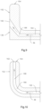
- the cooling channels 160 extending between the cooling cavity 158 and such ejection slots 162 may generally include a first portion 164 and a second portion 166, e.g., as illustrated in Figs. 5 through 11 .
- the first portion 164 may be proximate to the cooling cavity 158 and may extend from the cooling cavity 158 to the second portion 166.
- the first portion 164 may be linear and may extend along a direction generally parallel to the outer surface 134 of the platform 132.
- the second portion 166 may then extend from the first portion 164 to the ejection slot 162, and the second portion 166 may be configured to make up the radial offset between the ejection slot 162 and the first portion 164 and/or cooling cavity 158.
- the second portion 166 may have additional features as well.
- the second portion 166 is arcuate, e.g., the cooling channel 160 may comprise a first, portion 164 which is linear and a second portion 166 which is arcuate.
- the second portion 166 may be linear and may be oblique to the first portion 164 of the cooling channel 160.
- the invention includes an axial lip 144 formed in the forward rail 150 of the tip shroud 116, e.g., the axial lip 144 may be a step or lip which projects upstream along the axial direction from the forward rail 150 and/or forward surface 136.
- the axial lip 144 may define a rounded radially inner corner. In some embodiments, such as the illustrated embodiment of Fig. 6 , the axial lip 144 may define a chamfered radially inner corner which may advantageously reduce the weight of the tip shroud 116.
- the ejection slot may be axially oriented and may be formed in an outer surface 146 of the axial lip 144. Thus, in such embodiments, the ejection slot 162 may be configured to direct the cooling flow 36 radially outward and perpendicular to the hot gas path 32 of the turbomachine 10.
- the second portion 166 of the cooling channel 160 may be oblique to the first portion 164 and the ejection slot 162 may be formed in the forward surface 152 of the forward seal rail 150.
- the ejection slot 162 may be radially oriented and may be configured to direct the cooling flow 36 radially outward and oblique to the hot gas path 32 of the turbomachine 10.
- the cooling channel 160 may include a prismatic portion, e.g., the first portion 164 proximate to the cooling cavity 158 may be prismatic, and the cooling channel 160 may further include a non-prismatic portion, e.g., the second portion 166 may be non-prismatic.
- the non-prismatic portion may be a converging portion, as shown in Fig. 8 , or a diverging portion, as shown in Fig. 9 .
- Fig. 8 a converging portion
- a diverging portion as shown in Fig. 9 .
- the cooling channel 160 may include a converging portion, e.g., the second portion 166 of the cooling channel 160 extending between the prismatic first portion 164 of the cooling channel 160 and the ejection slot 162 may have converging side walls such that the cross-sectional area of the cooling channel 160 decreases from the first portion 164 to the ejection slot 162.
- the non-prismatic portion may in various other embodiments have curvilinear side walls. Further, the non-prismatic portion may include a converging part and a diverging part in various combinations.
- the ejection slot 162 may be axially oriented and may be formed in an outer surface 154 of the forward rail 150 of the tip shroud 116.
- the cooling channel 160 may include a linear first portion 164 which extends generally parallel to outer surface 134, an arcuate second portion 166 which extends between the first portion 164 and the ejection slot 162, e.g., from the first portion 164 to a third portion 168, where the third portion 168 extends from the second portion 166 to the ejection slot 162.
- the third portion 168 may extend along a direction that is generally parallel to the forward surface 152 of the forward rail 150.
- the example embodiment includes a rounded radially inner corner of the platform 132 of the tip shroud 116. It is also possible in other example embodiments to provide a chamfered radially inner corner of the platform 132 of the tip shroud 116, and some such embodiments may also include a linear second portion 166 of the cooling channel 160 which may be oblique to the first portion 164 and the third portion 168. Further, the linear second portion 166 may, for example, extend along a direction that is generally parallel to the chamfered radially inner corner of the platform 132 of the tip shroud 116.
- the second portion 166 may have additional features as well, such as turbulator features. Such turbulator features may create turbulence in the cooling flow 36 flowing through the cooling channel 160, which increases the rate of convective heat transfer from the tip shroud 116 by the cooling flow 36.
- the second portion 166 may have an undulating shape to create turbulence in the cooling flow 36 therethrough.
- the second portion 166 may include a plurality of projections 170 formed therein to create turbulence in the cooling flow 36 therethrough.
- the ejection slot 161 may be formed in forward surface 136, e.g., cooling flow 36 emanating from the existing ejection slot 161 may be directed head-to-head with the combustion gases 34.
- an example method may include a step of plugging the existing ejection slot 161.
- the example method may further include forming a new ejection slot 162 radially outward of the existing ejection slot 161.
- the new ejection slot 162 may be formed in the forward rail 150, e.g., in the forward surface 152 thereof.
- the example method may further include forming a bore 163 from the new ejection slot 162 to an intermediate portion of the cooling channel 160, as shown in Fig. 14 .
Landscapes
- Engineering & Computer Science (AREA)
- Mechanical Engineering (AREA)
- General Engineering & Computer Science (AREA)
- Turbine Rotor Nozzle Sealing (AREA)
Claims (7)
- Schaufel (100) für eine Turbomaschine (10), umfassend:ein Schaufelblatt (114), das sich radial zwischen einer Wurzel (118) und einer Spitze erstreckt, wobei das Schaufelblatt (114) eine Druckseitenoberfläche (122), die sich von einer Vorderkante (126) zu einer Hinterkante (128) erstreckt, und eine Saugseitenoberfläche (124), die sich von der Vorderkante (126) zu der Hinterkante (128) gegenüber der Druckseitenoberfläche (122) erstreckt, einschließt;eine Spitzenummantelung (116), die mit der äußeren Spitze des Schaufelblatts (114) verbunden ist, die Spitzenummantelung (116) umfassend:eine Plattform (132), umfassend eine Außenoberfläche (134), die sich im Allgemeinen senkrecht zu dem Schaufelblatt (114) erstreckt, derart, dass die Plattform einen Winkel von achtzig Grad bis einhundert Grad mit dem Schaufelblatt erzeugt, eine vordere Oberfläche (136), die im Allgemeinen senkrecht zu einem Heißgaspfad (32) der Turbomaschine (10) ausgerichtet ist, derart, dass die vordere Oberfläche einen Winkel von achtzig Grad bis einhundert Grad mit dem Heißgaspfad erzeugt, wobei die vordere Oberfläche nahe der Vorderkante (126) des Schaufelblatts (114) liegt, eine hintere Oberfläche (138) nahe der Hinterkante des Schaufelblatts (114) liegt, eine erste Seitenoberfläche (140), die sich zwischen der vorderen Oberfläche (136) und der hinteren Oberfläche (138) nahe der Druckseitenoberfläche (122) des Schaufelblatts (114) erstreckt, und eine zweite Seitenoberfläche (142), die sich zwischen der vorderen Oberfläche (136) und der hinteren Oberfläche (138) nahe der Saugseitenoberfläche (124) des Schaufelblatts (114) erstreckt;eine vordere Schiene (150), die sich von der Außenoberfläche (134) der Plattform (132) nahe der vorderen Oberfläche (136) der Plattform (132) radial nach außen erstreckt, wobei die vordere Schiene (150) im Allgemeinen senkrecht zu dem Heißgaspfad (32) der Turbomaschine (10) ausgerichtet ist, derart, dass die vordere Schiene einen Winkel von achtzig Grad bis einhundert Grad mit dem Heißgaspfad erzeugt;einen Kühlhohlraum (158), der in einem mittleren Abschnitt der Plattform der Spitzenummantelung definiert ist; undeinen Kühlkanal (160), der sich zwischen dem Kühlhohlraum (158) und einem Ausstoßschlitz (162) erstreckt, der in der vorderen Schiene (150) ausgebildet ist, wobei der Ausstoßschlitz (162) von der Außenoberfläche (134) der Plattform (132) der Spitzenummantelung (116) radial nach außen positioniert ist, wobei der Kühlkanal (160) einen ersten Abschnitt nahe des Kühlhohlraums (158) umfasst, wobei sich der erste Abschnitt parallel zu der Außenoberfläche der Plattform (132) zwischen dem Kühlhohlraum und einem zweiten Abschnitt des Kühlkanals schräg zu dem ersten Abschnitt des Kühlkanals erstreckt, wobei sich der zweite Abschnitt des Kühlkanals zwischen dem ersten Abschnitt des Kühlkanals und dem Ausstoßschlitz (162) erstreckt,die Schaufel ferner umfassend eine axiale Lippe (144), die in der vorderen Schiene (150) der Spitzenummantelung (116) ausgebildet ist und sich von der vorderen Schiene stromaufwärts erstreckt,wobei der Ausstoßschlitz (162) in einer Außenoberfläche (146) der axialen Lippe ausgebildet ist.
- Schaufel (100) nach Anspruch 1, wobei der Ausstoßschlitz (162) konfiguriert ist, um einen Kühlstrom radial nach außen und schräg zu dem Heißgaspfad (32) der Turbomaschine (10) zu leiten.
- Schaufel (100) nach Anspruch 1, wobei der Ausstoßschlitz (162) konfiguriert ist, um einen Kühlstrom radial nach außen und senkrecht zu dem Heißgaspfad (32) der Turbomaschine (10) zu leiten.
- Schaufel (100) nach Anspruch 1, wobei der Ausstoßschlitz (162) radial ausgerichtet ist.
- Gasturbine (10), umfassend;einen Verdichter (14);eine Brennkammer (16), die stromabwärts von dem Verdichter (14) angeordnet ist;eine Turbine (18), die stromabwärts von der Brennkammer (14) angeordnet ist, wobei die Turbine (18) eine Rotorwelle (24), die sich axial durch die Turbine (10) erstreckt, ein Außengehäuse (30), das die Rotorwelle (24) in Umfangsrichtung umgibt, um einen Heißgaspfad (32) dazwischen zu definieren, und eine Vielzahl von Rotorschaufeln (28), die mit der Rotorwelle (24) miteinander verbunden sind und eine Stufe von Rotorschaufeln (28) definieren, einschließt, wobei jede Rotorschaufel (28) eine Schaufel nach einem der Ansprüche 1 bis 4 umfasst.
- Gasturbine (10) nach Anspruch 5, wobei der Ausstoßschlitz (162) konfiguriert ist, um einen Kühlstrom radial nach außen und schräg zu dem Heißgaspfad (32) zu leiten.
- Gasturbine (10) nach Anspruch 6, wobei der Ausstoßschlitz (162) konfiguriert ist, um einen Kühlstrom radial nach außen und senkrecht zu dem Heißgaspfad (32) zu leiten.
Applications Claiming Priority (1)
| Application Number | Priority Date | Filing Date | Title |
|---|---|---|---|
| US15/620,896 US10704406B2 (en) | 2017-06-13 | 2017-06-13 | Turbomachine blade cooling structure and related methods |
Publications (2)
| Publication Number | Publication Date |
|---|---|
| EP3415719A1 EP3415719A1 (de) | 2018-12-19 |
| EP3415719B1 true EP3415719B1 (de) | 2024-04-24 |
Family
ID=62530112
Family Applications (1)
| Application Number | Title | Priority Date | Filing Date |
|---|---|---|---|
| EP18175821.0A Active EP3415719B1 (de) | 2017-06-13 | 2018-06-04 | Kühlstruktur einer turbomaschinenschaufel |
Country Status (4)
| Country | Link |
|---|---|
| US (1) | US10704406B2 (de) |
| EP (1) | EP3415719B1 (de) |
| JP (1) | JP7463051B2 (de) |
| CN (1) | CN109083686B (de) |
Families Citing this family (5)
| Publication number | Priority date | Publication date | Assignee | Title |
|---|---|---|---|---|
| KR101984397B1 (ko) * | 2017-09-29 | 2019-05-30 | 두산중공업 주식회사 | 로터, 터빈 및 이를 포함하는 가스터빈 |
| US10822987B1 (en) | 2019-04-16 | 2020-11-03 | Pratt & Whitney Canada Corp. | Turbine stator outer shroud cooling fins |
| FR3099786B1 (fr) * | 2019-08-07 | 2021-07-30 | Safran Helicopter Engines | Aube mobile pour une roue d’une turbomachine |
| EP4039941B1 (de) * | 2021-02-04 | 2023-06-28 | Doosan Enerbility Co., Ltd. | Schaufelblatt mit einem system zur kühlung verjüngter schaufelspitzen für eine turbinenlaufschaufel, turbinenlaufschaufel, turbinenlaufschaufelanordnung, gasturbine und verfahren zur herstellung eines schaufelblatts |
| US11692513B2 (en) * | 2021-11-01 | 2023-07-04 | Yuriy Radzikh | Electric jet engine |
Family Cites Families (31)
| Publication number | Priority date | Publication date | Assignee | Title |
|---|---|---|---|---|
| JPH1113402A (ja) * | 1997-06-23 | 1999-01-19 | Mitsubishi Heavy Ind Ltd | ガスタービン冷却翼チップシュラウド |
| EP0935052B1 (de) | 1998-02-04 | 2006-05-03 | Mitsubishi Heavy Industries, Ltd. | Gasturbinenlaufschaufel |
| DE19904229A1 (de) | 1999-02-03 | 2000-08-10 | Asea Brown Boveri | Gekühlte Turbinenschaufel |
| US6494678B1 (en) * | 2001-05-31 | 2002-12-17 | General Electric Company | Film cooled blade tip |
| GB2413160B (en) * | 2004-04-17 | 2006-08-09 | Rolls Royce Plc | Turbine rotor blades |
| JP4872410B2 (ja) * | 2005-04-04 | 2012-02-08 | 株式会社日立製作所 | 内部に冷却通路を有する部材及びその冷却方法 |
| GB2434842A (en) | 2006-02-02 | 2007-08-08 | Rolls Royce Plc | Cooling arrangement for a turbine blade shroud |
| US7686581B2 (en) | 2006-06-07 | 2010-03-30 | General Electric Company | Serpentine cooling circuit and method for cooling tip shroud |
| US7740442B2 (en) * | 2006-11-30 | 2010-06-22 | General Electric Company | Methods and system for cooling integral turbine nozzle and shroud assemblies |
| US7946816B2 (en) | 2008-01-10 | 2011-05-24 | General Electric Company | Turbine blade tip shroud |
| US8057177B2 (en) | 2008-01-10 | 2011-11-15 | General Electric Company | Turbine blade tip shroud |
| US8061987B1 (en) * | 2008-08-21 | 2011-11-22 | Florida Turbine Technologies, Inc. | Turbine blade with tip rail cooling |
| US8113779B1 (en) * | 2008-09-12 | 2012-02-14 | Florida Turbine Technologies, Inc. | Turbine blade with tip rail cooling and sealing |
| US8313301B2 (en) | 2009-01-30 | 2012-11-20 | United Technologies Corporation | Cooled turbine blade shroud |
| CH700686A1 (de) | 2009-03-30 | 2010-09-30 | Alstom Technology Ltd | Schaufel für eine gasturbine. |
| US8066485B1 (en) * | 2009-05-15 | 2011-11-29 | Florida Turbine Technologies, Inc. | Turbine blade with tip section cooling |
| US8414265B2 (en) * | 2009-10-21 | 2013-04-09 | General Electric Company | Turbines and turbine blade winglets |
| GB201006451D0 (en) | 2010-04-19 | 2010-06-02 | Rolls Royce Plc | Blades |
| EP2385215A1 (de) | 2010-05-05 | 2011-11-09 | Alstom Technology Ltd | Leichte Deckband-Dichtrippe für eine Rotorschaufel |
| US20120195742A1 (en) * | 2011-01-28 | 2012-08-02 | Jain Sanjeev Kumar | Turbine bucket for use in gas turbine engines and methods for fabricating the same |
| US8956104B2 (en) | 2011-10-12 | 2015-02-17 | General Electric Company | Bucket assembly for turbine system |
| US9127560B2 (en) * | 2011-12-01 | 2015-09-08 | General Electric Company | Cooled turbine blade and method for cooling a turbine blade |
| US9188012B2 (en) * | 2012-05-24 | 2015-11-17 | General Electric Company | Cooling structures in the tips of turbine rotor blades |
| US20140023497A1 (en) | 2012-07-19 | 2014-01-23 | General Electric Company | Cooled turbine blade tip shroud with film/purge holes |
| US9273561B2 (en) * | 2012-08-03 | 2016-03-01 | General Electric Company | Cooling structures for turbine rotor blade tips |
| US8920123B2 (en) * | 2012-12-14 | 2014-12-30 | Siemens Aktiengesellschaft | Turbine blade with integrated serpentine and axial tip cooling circuits |
| US9528380B2 (en) * | 2013-12-18 | 2016-12-27 | General Electric Company | Turbine bucket and method for cooling a turbine bucket of a gas turbine engine |
| US9909436B2 (en) * | 2015-07-16 | 2018-03-06 | General Electric Company | Cooling structure for stationary blade |
| US10156144B2 (en) * | 2015-09-30 | 2018-12-18 | United Technologies Corporation | Turbine airfoil and method of cooling |
| US10301945B2 (en) | 2015-12-18 | 2019-05-28 | General Electric Company | Interior cooling configurations in turbine rotor blades |
| US10184342B2 (en) | 2016-04-14 | 2019-01-22 | General Electric Company | System for cooling seal rails of tip shroud of turbine blade |
-
2017
- 2017-06-13 US US15/620,896 patent/US10704406B2/en active Active
-
2018
- 2018-06-04 EP EP18175821.0A patent/EP3415719B1/de active Active
- 2018-06-08 JP JP2018109922A patent/JP7463051B2/ja active Active
- 2018-06-13 CN CN201810607667.6A patent/CN109083686B/zh active Active
Also Published As
| Publication number | Publication date |
|---|---|
| JP7463051B2 (ja) | 2024-04-08 |
| EP3415719A1 (de) | 2018-12-19 |
| JP2019002401A (ja) | 2019-01-10 |
| CN109083686B (zh) | 2023-08-04 |
| US10704406B2 (en) | 2020-07-07 |
| CN109083686A (zh) | 2018-12-25 |
| US20180355727A1 (en) | 2018-12-13 |
Similar Documents
| Publication | Publication Date | Title |
|---|---|---|
| EP3415719B1 (de) | Kühlstruktur einer turbomaschinenschaufel | |
| EP3088675B1 (de) | Laufschaufel und zugehörige gasturbine | |
| CN106089313B (zh) | 具有外扩末梢的转子叶片 | |
| EP3214271A1 (de) | Rotorschaufel mit hinterkantenkühlung | |
| US10066488B2 (en) | Turbomachine blade with generally radial cooling conduit to wheel space | |
| EP2634370B1 (de) | Turbinenschaufel mit einem Kernhohlraum mit einer konturierten Drehung | |
| US10830082B2 (en) | Systems including rotor blade tips and circumferentially grooved shrouds | |
| EP3203024A1 (de) | Laufschaufel und zugehörige gasturbine | |
| JP7297413B2 (ja) | ターボ機械用ロータブレード | |
| EP3249162B1 (de) | Laufschaufel und zugehöriges gasturbinensystem | |
| EP3412869B1 (de) | Turbomaschinenrotorschaufel | |
| US10494932B2 (en) | Turbomachine rotor blade cooling passage | |
| US10590777B2 (en) | Turbomachine rotor blade | |
| US10472974B2 (en) | Turbomachine rotor blade | |
| US10577945B2 (en) | Turbomachine rotor blade | |
| EP3336317B1 (de) | Kühltasche für die plattform einer turbinenleitschaufel | |
| US20190003320A1 (en) | Turbomachine rotor blade | |
| US11629601B2 (en) | Turbomachine rotor blade with a cooling circuit having an offset rib | |
| US10746029B2 (en) | Turbomachine rotor blade tip shroud cavity | |
| US10633979B2 (en) | Turbomachine rotor blade pocket | |
| US20180216474A1 (en) | Turbomachine Blade Cooling Cavity |
Legal Events
| Date | Code | Title | Description |
|---|---|---|---|
| PUAI | Public reference made under article 153(3) epc to a published international application that has entered the european phase |
Free format text: ORIGINAL CODE: 0009012 |
|
| STAA | Information on the status of an ep patent application or granted ep patent |
Free format text: STATUS: THE APPLICATION HAS BEEN PUBLISHED |
|
| AK | Designated contracting states |
Kind code of ref document: A1 Designated state(s): AL AT BE BG CH CY CZ DE DK EE ES FI FR GB GR HR HU IE IS IT LI LT LU LV MC MK MT NL NO PL PT RO RS SE SI SK SM TR |
|
| AX | Request for extension of the european patent |
Extension state: BA ME |
|
| STAA | Information on the status of an ep patent application or granted ep patent |
Free format text: STATUS: REQUEST FOR EXAMINATION WAS MADE |
|
| 17P | Request for examination filed |
Effective date: 20190619 |
|
| RBV | Designated contracting states (corrected) |
Designated state(s): AL AT BE BG CH CY CZ DE DK EE ES FI FR GB GR HR HU IE IS IT LI LT LU LV MC MK MT NL NO PL PT RO RS SE SI SK SM TR |
|
| STAA | Information on the status of an ep patent application or granted ep patent |
Free format text: STATUS: EXAMINATION IS IN PROGRESS |
|
| STAA | Information on the status of an ep patent application or granted ep patent |
Free format text: STATUS: EXAMINATION IS IN PROGRESS |
|
| 17Q | First examination report despatched |
Effective date: 20210125 |
|
| STAA | Information on the status of an ep patent application or granted ep patent |
Free format text: STATUS: EXAMINATION IS IN PROGRESS |
|
| RAP1 | Party data changed (applicant data changed or rights of an application transferred) |
Owner name: GENERAL ELECTRIC TECHNOLOGY GMBH |
|
| GRAP | Despatch of communication of intention to grant a patent |
Free format text: ORIGINAL CODE: EPIDOSNIGR1 |
|
| STAA | Information on the status of an ep patent application or granted ep patent |
Free format text: STATUS: GRANT OF PATENT IS INTENDED |
|
| INTG | Intention to grant announced |
Effective date: 20240117 |
|
| GRAS | Grant fee paid |
Free format text: ORIGINAL CODE: EPIDOSNIGR3 |
|
| GRAA | (expected) grant |
Free format text: ORIGINAL CODE: 0009210 |
|
| STAA | Information on the status of an ep patent application or granted ep patent |
Free format text: STATUS: THE PATENT HAS BEEN GRANTED |
|
| AK | Designated contracting states |
Kind code of ref document: B1 Designated state(s): AL AT BE BG CH CY CZ DE DK EE ES FI FR GB GR HR HU IE IS IT LI LT LU LV MC MK MT NL NO PL PT RO RS SE SI SK SM TR |
|
| REG | Reference to a national code |
Ref country code: GB Ref legal event code: FG4D |
|
| REG | Reference to a national code |
Ref country code: CH Ref legal event code: EP |
|
| REG | Reference to a national code |
Ref country code: DE Ref legal event code: R096 Ref document number: 602018068456 Country of ref document: DE |
|
| REG | Reference to a national code |
Ref country code: IE Ref legal event code: FG4D |