EP3415302B1 - Oberflächenbehandlungsverfahren und oberflächenbehandlungsvorrichtung für harzgefäss - Google Patents
Oberflächenbehandlungsverfahren und oberflächenbehandlungsvorrichtung für harzgefäss Download PDFInfo
- Publication number
- EP3415302B1 EP3415302B1 EP18177604.8A EP18177604A EP3415302B1 EP 3415302 B1 EP3415302 B1 EP 3415302B1 EP 18177604 A EP18177604 A EP 18177604A EP 3415302 B1 EP3415302 B1 EP 3415302B1
- Authority
- EP
- European Patent Office
- Prior art keywords
- resin vessel
- electron beam
- vessel
- resin
- coating
- Prior art date
- Legal status (The legal status is an assumption and is not a legal conclusion. Google has not performed a legal analysis and makes no representation as to the accuracy of the status listed.)
- Active
Links
Images



Classifications
-
- B—PERFORMING OPERATIONS; TRANSPORTING
- B65—CONVEYING; PACKING; STORING; HANDLING THIN OR FILAMENTARY MATERIAL
- B65B—MACHINES, APPARATUS OR DEVICES FOR, OR METHODS OF, PACKAGING ARTICLES OR MATERIALS; UNPACKING
- B65B55/00—Preserving, protecting or purifying packages or package contents in association with packaging
- B65B55/24—Cleaning of, or removing dust from, containers, wrappers, or packaging ; Preventing of fouling
-
- A—HUMAN NECESSITIES
- A61—MEDICAL OR VETERINARY SCIENCE; HYGIENE
- A61L—METHODS OR APPARATUS FOR STERILISING MATERIALS OR OBJECTS IN GENERAL; DISINFECTION, STERILISATION OR DEODORISATION OF AIR; CHEMICAL ASPECTS OF BANDAGES, DRESSINGS, ABSORBENT PADS OR SURGICAL ARTICLES; MATERIALS FOR BANDAGES, DRESSINGS, ABSORBENT PADS OR SURGICAL ARTICLES
- A61L2/00—Disinfection or sterilisation of materials or objects, in general; Accessories therefor
- A61L2/02—Disinfection or sterilisation of materials or objects, in general; Accessories therefor using physical processes
- A61L2/08—Radiation
- A61L2/087—Particle radiation, e.g. electron-beam, alpha or beta radiation
-
- B—PERFORMING OPERATIONS; TRANSPORTING
- B29—WORKING OF PLASTICS; WORKING OF SUBSTANCES IN A PLASTIC STATE IN GENERAL
- B29C—SHAPING OR JOINING OF PLASTICS; SHAPING OF MATERIAL IN A PLASTIC STATE, NOT OTHERWISE PROVIDED FOR; AFTER-TREATMENT OF THE SHAPED PRODUCTS, e.g. REPAIRING
- B29C71/00—After-treatment of articles without altering their shape; Apparatus therefor
- B29C71/04—After-treatment of articles without altering their shape; Apparatus therefor by wave energy or particle radiation, e.g. for curing or vulcanising preformed articles
-
- C—CHEMISTRY; METALLURGY
- C08—ORGANIC MACROMOLECULAR COMPOUNDS; THEIR PREPARATION OR CHEMICAL WORKING-UP; COMPOSITIONS BASED THEREON
- C08J—WORKING-UP; GENERAL PROCESSES OF COMPOUNDING; AFTER-TREATMENT NOT COVERED BY SUBCLASSES C08B, C08C, C08F, C08G or C08H
- C08J7/00—Chemical treatment or coating of shaped articles made of macromolecular substances
- C08J7/12—Chemical modification
- C08J7/123—Treatment by wave energy or particle radiation
-
- B—PERFORMING OPERATIONS; TRANSPORTING
- B05—SPRAYING OR ATOMISING IN GENERAL; APPLYING FLUENT MATERIALS TO SURFACES, IN GENERAL
- B05D—PROCESSES FOR APPLYING FLUENT MATERIALS TO SURFACES, IN GENERAL
- B05D3/00—Pretreatment of surfaces to which liquids or other fluent materials are to be applied; After-treatment of applied coatings, e.g. intermediate treating of an applied coating preparatory to subsequent applications of liquids or other fluent materials
- B05D3/06—Pretreatment of surfaces to which liquids or other fluent materials are to be applied; After-treatment of applied coatings, e.g. intermediate treating of an applied coating preparatory to subsequent applications of liquids or other fluent materials by exposure to radiation
-
- B—PERFORMING OPERATIONS; TRANSPORTING
- B05—SPRAYING OR ATOMISING IN GENERAL; APPLYING FLUENT MATERIALS TO SURFACES, IN GENERAL
- B05D—PROCESSES FOR APPLYING FLUENT MATERIALS TO SURFACES, IN GENERAL
- B05D7/00—Processes, other than flocking, specially adapted for applying liquids or other fluent materials to particular surfaces or for applying particular liquids or other fluent materials
- B05D7/02—Processes, other than flocking, specially adapted for applying liquids or other fluent materials to particular surfaces or for applying particular liquids or other fluent materials to macromolecular substances, e.g. rubber
-
- B—PERFORMING OPERATIONS; TRANSPORTING
- B05—SPRAYING OR ATOMISING IN GENERAL; APPLYING FLUENT MATERIALS TO SURFACES, IN GENERAL
- B05D—PROCESSES FOR APPLYING FLUENT MATERIALS TO SURFACES, IN GENERAL
- B05D7/00—Processes, other than flocking, specially adapted for applying liquids or other fluent materials to particular surfaces or for applying particular liquids or other fluent materials
- B05D7/22—Processes, other than flocking, specially adapted for applying liquids or other fluent materials to particular surfaces or for applying particular liquids or other fluent materials to internal surfaces, e.g. of tubes
- B05D7/227—Processes, other than flocking, specially adapted for applying liquids or other fluent materials to particular surfaces or for applying particular liquids or other fluent materials to internal surfaces, e.g. of tubes of containers, cans or the like
-
- B—PERFORMING OPERATIONS; TRANSPORTING
- B29—WORKING OF PLASTICS; WORKING OF SUBSTANCES IN A PLASTIC STATE IN GENERAL
- B29C—SHAPING OR JOINING OF PLASTICS; SHAPING OF MATERIAL IN A PLASTIC STATE, NOT OTHERWISE PROVIDED FOR; AFTER-TREATMENT OF THE SHAPED PRODUCTS, e.g. REPAIRING
- B29C35/00—Heating, cooling or curing, e.g. crosslinking or vulcanising; Apparatus therefor
- B29C35/02—Heating or curing, e.g. crosslinking or vulcanizing during moulding, e.g. in a mould
- B29C35/08—Heating or curing, e.g. crosslinking or vulcanizing during moulding, e.g. in a mould by wave energy or particle radiation
- B29C35/0866—Heating or curing, e.g. crosslinking or vulcanizing during moulding, e.g. in a mould by wave energy or particle radiation using particle radiation
- B29C2035/0877—Heating or curing, e.g. crosslinking or vulcanizing during moulding, e.g. in a mould by wave energy or particle radiation using particle radiation using electron radiation, e.g. beta-rays
-
- C—CHEMISTRY; METALLURGY
- C08—ORGANIC MACROMOLECULAR COMPOUNDS; THEIR PREPARATION OR CHEMICAL WORKING-UP; COMPOSITIONS BASED THEREON
- C08J—WORKING-UP; GENERAL PROCESSES OF COMPOUNDING; AFTER-TREATMENT NOT COVERED BY SUBCLASSES C08B, C08C, C08F, C08G or C08H
- C08J2300/00—Characterised by the use of unspecified polymers
- C08J2300/22—Thermoplastic resins
-
- C—CHEMISTRY; METALLURGY
- C08—ORGANIC MACROMOLECULAR COMPOUNDS; THEIR PREPARATION OR CHEMICAL WORKING-UP; COMPOSITIONS BASED THEREON
- C08J—WORKING-UP; GENERAL PROCESSES OF COMPOUNDING; AFTER-TREATMENT NOT COVERED BY SUBCLASSES C08B, C08C, C08F, C08G or C08H
- C08J2367/00—Characterised by the use of polyesters obtained by reactions forming a carboxylic ester link in the main chain; Derivatives of such polymers
- C08J2367/02—Polyesters derived from dicarboxylic acids and dihydroxy compounds
Definitions
- the present invention relates to a surface treatment method and a surface treatment device for a resin vessel, which perform coating or modification treatment on the surface of the resin vessel.
- the surface of the resin vessel has been coated or modified to reduce the gas permeability of the resin vessel.
- Japanese Laid-Open Patent Application No. 2007-70734 describes a method in which a resin vessel is located in a depressurized environment, a material gas for coating is supplied to the inside of the resin vessel, and further, plasma is generated between an outer electrode provided outside the resin vessel and an inner electrode provided inside the resin vessel, to activate the material gas and perform coating on the inner surface of the resin vessel.
- Japanese Patent No. 3952695 describes a method in which a resin vessel is accommodated into a storage chamber, the storage chamber is supplied with a material gas while being depressurized, plasma is further generated in the storage chamber, a positive high voltage pulse is applied to an electrode inserted into the resin vessel, and ions are implanted into a surface layer of the resin vessel to modify the surface.
- the present invention is to provide a surface treatment method and a surface treatment device for a resin vessel which are capable of performing coating or modification treatment on the surface of a resin vessel at high speed.
- US Patent Application US 2005/0191435 A1 describes coating tanks with a barrier coating by various techniques, such as dipping or application with a brush or roller. The tanks are exposed to a reactive gas, with the aim of causing coatings to adhere well and retain impact resistance.
- European Patent Application EP 1 849 746 A1 discloses an apparatus which sterilizes vessels by irradiating the vessels with an electron beam and exposing them to H 2 O 2 gas.
- French Patent Application FR 2 872 148 describes a machine for treating containers by deposition of an inner barrier coating by means of a microwave plasma in a vacuum chamber.
- a surface treatment method for a resin vessel is provided, as set out in claim 1.
- a surface treatment device for a resin vessel is provided, as set out in claim 5.
- the resin vessel, to which the material for coating or surface modification has been applied is irradiated with the electron beam, whereby it is possible to form a coating or perform modification treatment on the surface of the resin vessel.
- the environment is set at pressure equal to or higher than the atmospheric pressure, thereby eliminating the need for the depressurization step as in Japanese Laid-Open Patent Application No. 2007-70734 and Japanese Patent No. 3952695 described above and enabling high-speed treatment.
- the resin vessel can be sterilized simultaneously due to the irradiation with the electron beam, thereby eliminating the need to separately perform the coating or the surface treatment on the resin vessel and the sterilization and enabling efficient treatment.
- FIG. 1 shows a surface treatment device 2 according to a first example, which performs coating or modification treatment on the surface of a resin vessel 1 such as a polyethylene terephthalate bottle and constitutes a part of a filling line for filling the resin vessel 1 with beverage.
- a resin vessel 1 such as a polyethylene terephthalate bottle
- the resin vessel 1 includes a body 1a with which beverage or the like is filled, a neck portion 1b provided in an upper part of the body 1a and mounted with a cap, and a flange portion 1c provided in a lower part of the neck portion 1b, and a lower part of the flange portion 1c is supported at the time of carrying the resin vessel 1.
- a coating is formed or surface modification is performed on the inner surface and the outer surface of the resin vessel 1.
- a material for the coating or the surface modification is applied to the outer surface and the inner surface of the resin vessel 1, and then the resin vessel 1, to which the material has been applied, is irradiated with an electron beam, to perform the coating or the surface modification.
- a material of a component containing hydrocarbons such as acetylene, toluene, or xylene
- a material of a component containing silane such as tetramethylsilane, or some other material can be used.
- the surface treatment device 2 includes: a sterilization chamber 3 with its inside kept in a sterilized state; a vessel carrier unit 4 that carries the resin vessel 1 in the sterilization chamber 3; a material injection unit 5 that applies the material to the resin vessel 1; an electron beam irradiation unit 6 that irradiates the resin vessel 1, to which the material has been applied, with an electron beam; and an aeration unit 7 that discharges the material for the surface treatment and the like from the inside of the resin vessel 1.
- a wall surface constituting the sterilization chamber 3 is made of lead that shields the electron beam, with which the resin vessel 1 is irradiated, and the inside of the sterilization chamber 3 is kept in the sterilized state by a sterilized air supply unit, not shown.
- a take-in room 3A and a taken-out room 3B are respectively connected to the upstream side and the downstream side of a path for carrying by the vessel carrier unit 4 in the sterilization chamber 3, while being kept in an airtight and sterilized state, and a partition plate P is provided on a boundary between these chambers.
- the pressure inside the sterilization chamber 3 is set to be higher than the atmospheric pressure and to be higher than the pressure in each of the take-in room 3A and the taken-out room 3B, so that a foreign material from the outside is prevented from entering the sterilization chamber 3.
- the inside of the sterilization chamber 3 is further divided into three spaces Sa to Sc with two partition plates P.
- the partition plate P provided between the spaces Sa and Sb divides the space into an inner surface injection section A in which the material is applied to the inner surface of the resin vessel 1 described below and an electron beam irradiation section B in which irradiation is performed with the electron beam and the material is applied to the outer surface of the resin vessel 1.
- the partition plate P provided between the spaces Sb and Sc divides the space into the electron beam irradiation section B and a space on the downstream side thereof.
- the spaces Sa to Sc are set such that the pressure in the space located on the downstream side is higher than the pressure in the space located on the upstream side.
- the material injected in the inner surface injection section A is prevented from entering into the space Sb between the space Sa and the space Sb, and the material injected in the electron beam irradiation section B is prevented from entering into the space Sc between the space Sb and the space Sc.
- the vessel carrier unit 4 includes first to sixth star wheels 8A to 8F provided from the take-in room 3A to the taken-out room 3B of the sterilization chamber 3 and can continuously carry the resin vessel 1 at high speed.
- the injection of the material and the irradiation with the electron beam, intended to coat the resin vessel 1, are performed on the path along which the resin vessel 1 is carried by the third star wheel 8C.
- Grippers G for holding the resin vessel 1 are provided on each of the first to sixth star wheels 8A to 8E, and at each reception and passing position where the star wheels are adjacent to each other, the resin vessel 1 is passed from the gripper G on the upstream star wheel to the gripper G on the downstream star wheel.
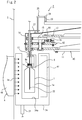
- FIG. 2 shows a sectional view showing positions of the resin vessel 1 carried by the third star wheel 8C and the electron beam irradiation unit 6.
- the third star wheel 8C includes a rotation table 11 rotated by a drive unit, not shown, and the grippers G are provided at regular intervals along the outer periphery of the rotation table 11.
- Each gripper G includes a pair of holding members energized by a spring, and a lower part of the flange portion 1c of the resin vessel 1 is sandwiched between the holding members. Note that the gripper G having such a configuration is conventionally known, and hence the detailed description thereof will be omitted.
- the gripper G of the present example is provided on the rotation table 11 so as to be horizontally rotatable by the rotation unit 12, thereby rotating the resin vessel 1 held by the gripper G.
- the rotation unit 12 includes: a rotation axis 13 rotatably provided on the rotation table 11; a pinion gear 14 provided at the upper end of the rotation axis 13; a segment gear 15 swingably provided on the rotation table 11 and meshed with the pinion gear 14; a cam follower 16 coupled to the segment gear 15; and a cam 17 provided separately from the rotation table 11 and configured to move the cam follower 16.
- the segment gear 15 rotates the rotation axis 13 by being meshed with the pinion gear 14, a spring 18 with one end coupled to the rotation table 11 is coupled to the segment gear 15, and the cam follower 16 is located on the center side of the rotation table 11 by energizing force of the spring 18.
- the gripper G is rotated by 180° so that one side surface and the other side surface of the resin vessel 1 held by the gripper G are each turned to the outer peripheral side of the rotation table 11.
- the material injection unit 5 is comprised of an outer surface nozzle 21 that applies the material to the outer surface of the resin vessel 1, an inner surface nozzle 22 that applies the material to the inner surface, and a supply unit 23 that supplies the material to the outer surface nozzle 21 and the inner surface nozzle 22.
- the outer surface nozzle 21 is provided on the bottom surface of a hollow injection booth 24 set up inside the sterilization chamber 3, and the injection booth 24 is provided in the electron beam irradiation section B in which the irradiation is performed by the electron beam irradiation unit 6, as shown in FIG. 1 .
- FIG. 3 shows a perspective view of the injection booth 24 having a configuration where a slit 24a, which is passable by the resin vessel 1 carried by the vessel carrier unit 4, is formed in the center of a hollow box-shaped body having a shape that is substantially a rectangular parallelepiped.
- the longitudinal length of the injection booth 24 is set equivalent to or slightly larger than the length of the electron beam irradiation section B in which the irradiation is performed by the electron beam irradiation unit 6, and on the bottom part of the injection booth 24, a plurality of the outer surface nozzles 21 are provided along the carrier path for the resin vessel 1.
- the outer surface nozzle 21 then injects the material to the inside of the injection booth 24, so that it is possible to apply the material to the outer surface of the resin vessel 1 and prevent the injected material from scattering outside the injection booth 24.
- the outer surface nozzle 21 is disposed on the outer peripheral side of the rotation table 11 with respect to the center of the carried resin vessel 1, and a larger amount of material is injected to the side where the irradiation is performed with the electron beam by the electron beam irradiation unit 6.
- the inner surface nozzle 22 is provided at the same intervals as the grippers G provided on the rotation table 11 and provided liftably by a lifting unit 25 while vertically passing through the inside of the tubular rotation axis 13 pivotally supported by the rotation table 11. Further, the inner surface nozzle 22 is provided rotatably by a rotary joint 22a provided on the upper part of the inner surface nozzle 22.
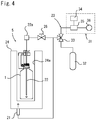
- the inner surface nozzle 22 controls the supply and stoppage of the material with an opening/closing valve 26 shown in FIG. 4 , and in the present example, the inner surface nozzle 22 injects the material to the inside of the resin vessel 1 in the inner surface injection section A set on the upstream side of the electron beam irradiation section B shown in FIG. 1 .
- the inner surface nozzle 22 of the present example is comprised of a metal member having a tubular shape and constitutes an earth electrode bar for preventing electrification inside the resin vessel 1 at the time of irradiating the resin vessel 1 with the electron beam by the electron beam irradiation unit 6 as described below.
- the lifting unit 25 is comprised of a support member 27 that supports the inner surface nozzle 22, a cam follower 28 provided in the support member 27, and a cam 29 provided separately from the rotation table 11.
- the inner surface nozzle 22 is vertically lifted or lowered by the cam follower 28 following the cam 29 and moving vertically.
- the lifting unit 25 lowers the inner surface nozzle 22 to the inside of the resin vessel 1, and when the third star wheel 8C passes the resin vessel 1 to the fourth star wheel 8D, the lifting unit 25 lifts and remove the inner surface nozzle 22 to the outside of the resin vessel 1.
- the material injection unit 5 includes: a vaporization supply unit 31 that vaporizes a liquid material and then supplies the vaporized material; a gas material tank 32 that supplies a gaseous material; and a three-way valve 33 for selectively supplying the vaporized material or the gaseous material to the inner surface nozzle 22 and the outer surface nozzle 21.
- the vaporization supply unit 31 includes a liquid material tank 34 that accommodates the liquid material, a vaporization unit 35 that vaporizes the liquid material, and a feeding unit 36 that feeds the vaporized material.
- the vaporization unit 35 vaporizes the liquid material supplied from the liquid material tank 34, and the feeding unit 36 feeds the vaporized material.
- gaseous material is accommodated in the gas material tank 32, and by inner pressure of the gas material tank 32, the gaseous material is discharged.
- a liquid may be sprayed to apply the material to the resin vessel 1.
- the three-way valve 33 supplies either the material vaporized by the vaporization supply unit 31 or the gaseous material provided by the gas material tank 32 to the inner surface nozzle 22 and the outer surface nozzle 21.
- the surface treatment device 2 of the present example it is possible to form a coating made up of a different material in response to a request.
- a toluene-based coating liquid toluene can be vaporized by the vaporization unit 35, and for example when an acetylene-based coating is to be formed, gaseous acetylene can be supplied from the gas material tank 32.
- a pipe from the supply unit 23 toward the inner surface nozzle 22 and the outer surface nozzle 21 is divided in the middle, and of the divided pipes, the divided pipe on the inner surface nozzle 22 side is provided with the opening/closing valve 26 for stopping the supply of the material to the inner surface nozzle 22.
- the electron beam irradiation unit 6 includes an irradiation machine 41 that is provided outside an irradiation window 3a provided on the side surface of the sterilization chamber 3 and performs irradiation with the electron beam.
- the irradiation machine 41 is conventionally known and the detailed description thereof will thus be omitted, but the irradiation machine 41 irradiates the resin vessel 1 with the electron beam by heating a filament inside a vacuum chamber to generate thermoelectrons, accelerating the electrons with a high voltage to form a high-speed electron beam, and then causing the electron beam to pass through a film made of metal such as Ti which is formed on the irradiation window 3a.
- the material is activated and an individual component of the material is applied to the surface of the resin vessel 1 to form a coating.
- the irradiation machine 41 of the present example can be set so as to perform irradiation with an electron beam at an acceleration voltage of 300 kV, a current of 5 mA, and a dose of 3.3 kG, but other settings can also be used so long as the resin vessel 1 can be sterilized by irradiation with the electron beam as described below while the material for the coating is activated.
- the electron beam applied from the irradiation machine 41 and transmitted through the resin that forms the resin vessel 1, attempts electrification inside the resin vessel 1, but the inner surface nozzle 22 as the earth electrode bar releases this electron beam to the outside of the resin vessel 1.
- a beam catcher 42 for absorbing the applied electron beam is provided in a position facing the irradiation window 3a.
- the beam catcher 42 is provided inside the injection booth 24 and on the opposite side of the resin vessel 1 from the irradiation machine 41, so as to absorb the applied electron beam and prevent diffusion of the electron beam to the outside.
- irradiating the material applied to the resin vessel 1 with the electron beam also enables surface modification of the resin vessel 1 instead of the coating described above.
- the material for the coating is activated to come into an unstable state, but at this time, the material constituting the resin vessel 1 is also activated to come into an unstable state.
- the above coating is formed when the activated coating material is applied to the surface of the resin vessel 1, but the surface modification is performed on the resin vessel 1 when the material is actively bound to the activated material surface of the resin vessel 1 to change the composition of the material surface.
- one of the coating and the surface modification may be performed, or both of those may be simultaneously performed, depending on the material constituting the resin vessel 1 and the type of the material for each of the coating and the surface modification, the time for irradiation with the electron beam, and the like.
- the electron beam irradiation unit 6 of the present example can sterilize the resin vessel 1 as well as forming the coating or performing the surface modification by irradiating the material applied to the resin vessel 1 with the electron beam.
- the aeration unit 7 is provided in the fifth star wheel 8E in FIG. 1 , and FIG. 5 shows a sectional view of the fifth star wheel 8E.
- the fifth star wheel 8E is also provided with the grippers G for holding the resin vessel 1 at regular intervals, and this gripper G is also configured to hold the lower part of the flange portion 1c of the resin vessel 1 from both sides by energizing force of a spring, not shown.
- the aeration unit 7 is comprised of: an aeration nozzle 43 that is inserted to the inside of the resin vessel 1; a lifting unit 44 that lifts or lowers the aeration nozzle 43; an air feeding unit 45 that supplies cleaned air to the aeration nozzle 43; and a suction unit 46 that supplies negative pressure to the aeration nozzle 43 to exhaust the air from the resin vessel 1.
- a three-way valve 47 is provided between the air feeding unit 45/suction unit 46 and the aeration nozzle 43, and the air from the air feeding unit 45 and the negative pressure from the suction unit 46 are switched to be supplied to the aeration nozzle 43.
- the resin vessel 1 is carried between a position for reception from the fourth star wheel 8D and a position for passing to the sixth star wheel 8F, and in the direction in which the resin vessel 1 is carried, a suction section C in which sucking is performed by the suction unit 46 is on the upstream side while an air supply section D in which the air is supplied from the air feeding unit 45 is on the downstream side.
- the lifting unit 44 has a similar configuration to that of the lifting unit 25 for lifting or lowering the inner surface nozzle 22 and the detailed description thereof will thus be omitted.
- the aeration nozzle 43 is inserted inside the resin vessel 1, and in the other position, the aeration nozzle 43 is removed to a place above the resin vessel 1.
- the inside of the sterilization chamber 3 is kept in the sterilized state and set at pressure higher than the atmospheric pressure.
- the inner surface nozzle 22 is lowered by the lifting unit 25 and inserted to the inside of the resin vessel 1.
- the step of applying the material for the surface treatment to the inner surface of the resin vessel 1 by using the inner surface nozzle 22 is performed.
- the three-way valve 33 is controlled so as to supply the material from either the vaporization unit 35 or the gas material tank 32 to the inner surface nozzle 22, and the opening/closing valve 26 is opened only during the time when the inner surface nozzle 22 moves in the inner surface injection section A.
- the inner surface injection section A in which the material is injected by the inner surface nozzle 22 may overlap with the electron beam irradiation section B, but when the resin vessel 1 is to be carried at high speed, it is desirable to set the inner surface injection section A on the upstream side of the electron beam irradiation section B as in the present example.
- the step of applying the material to the outer surface of the resin vessel 1 is performed simultaneously with the step of irradiating the resin vessel 1 with the electron beam.
- the resin vessel 1 carried by the vessel carrier unit 4 reaches the electron beam irradiation section B, the resin vessel 1 moves inside the injection booth 24 along the slit 24a, and during the movement, the material injected by the outer surface nozzle 21 is applied to the outer surface of the resin vessel 1.
- the electron beam irradiated by the electron beam irradiation unit 6 then activates the material applied to the outer surface and the inner surface of the resin vessel 1, whereby a coating is formed or surface modification is performed on each of the outer surface and the inner surface of the resin vessel 1.
- the rotation unit 12 rotates the gripper G by 180° at required timing, and thereby one side surface and the other side surface of the resin vessel 1 are irradiated with the electron beam to enable to form a coating or perform surface modification on the entire surface of the resin vessel 1.
- Electrons and ions existing inside the resin vessel 1 are drawn by the inner surface nozzle 22 as the earth electrode bar and then caused to flow to the outside, so that electrification of the resin vessel 1 can be prevented.
- the resin vessel 1 can be sterilized by irradiating the resin vessel 1 with the electron beam in the electron beam irradiation section B, and it is thus possible to simultaneously perform the surface treatment, such as the coating or the modification, and the sterilization on the surface of the resin vessel 1 without providing the sterilizer other than the surface treatment device 2.
- the aeration nozzle 43 is inserted to the inside of the resin vessel 1 by the lifting unit 44, and in the upstream suction section C, negative pressure is supplied to the inside of the resin vessel 1 to cause suction of the gas inside the resin vessel 1.
- the cleaned air is supplied to the inside of the resin vessel 1 and the gas inside the resin vessel 1 is replaced with the cleaned gas.
- the resin vessel 1 having completed the aeration is further carried by the vessel carrier unit 4 and filled with beverage or the like in a post process, not shown.
- the resin vessel 1 can be continuously carried using the star wheels, and the surface treatment can be performed on the inner surface and the outer surface of the resin vessel 1 at high speed.
- the coating or the surface modification is to be performed only on the outer surface of the resin vessel 1 in the configuration of the first example, it is sufficient that the material is not injected from the inner surface nozzle 22 in the above configuration.
- a solid earth electrode bar may be used in place of the inner surface nozzle 22, or the inner surface nozzle 22 may inject sterilized air or nitrogen instead of injecting the material.
- the material By injecting the sterilized air or nitrogen to the inside of the resin vessel 1, the material does not enter inside the resin vessel 1, so that it is possible to prevent the coating on the inner surface of the resin vessel 1 and prevent a foreign material from entering the beverage due to peeling of the coating.
- the coating or the surface treatment may be performed only on the inner surface of the resin vessel 1. In this case, it is sufficient that the material is prevented from being injected from the outer surface nozzle 21 in the above configuration.
- FIG. 6 is a view showing the surface treatment device 2 for the resin vessel 1 according to a second example, and with respect to the first example, instead of not performing the coating on the inner surface of the resin vessel 1, in order to sterilize the inside of the resin vessel 1, a gas made into plasma is supplied to the inside of the resin vessel 1 and the irradiation with the electron beam is further performed. Note that the description of the configuration in common with the configuration of the first example will be omitted.
- the inner surface nozzle 22 for supplying the plasma gas is provided inside the resin vessel 1, and similarly to the inner surface nozzle 22 in the first example, the inner surface nozzle 22 is lifted or lowered by the lifting unit 25.
- a plasma generation unit 51 that generates plasma
- a humidity adjustment unit 52 that adjusts the humidity of the plasma gas
- a feeding unit 53 that feeds the plasma gas.
- the supply of the plasma gas is stopped by the opening/closing valve 26 provided adjacent to the inner surface nozzle 22.
- the inner surface nozzle 22 supplies the plasma gas on the upstream side of the electron beam irradiation section B similarly to the inner surface injection section A of FIG. 1 .
- the plasma gas is injected to the inside of the resin vessel 1, so that the inside of the resin vessel 1 including the inner surface thereof can be sterilized by the plasma gas.
- the resin vessel 1 is irradiated with the electron beam, so that the outer surface and the inside of the resin vessel 1 can be sterilized by the electron beam.
- the plasma gas existing inside the resin vessel 1 is irradiated with the electron beam and is thereby excited to sterilize the inside of the resin vessel 1.
- the material for the surface treatment applied to the outer surface of the resin vessel 1 by the irradiation with the electron beam, is activated to perform the coating or the surface modification, and it is thus possible to simultaneously perform the surface treatment on the outer surface and sterilization on the inside.
Landscapes
- Chemical & Material Sciences (AREA)
- Health & Medical Sciences (AREA)
- General Chemical & Material Sciences (AREA)
- Polymers & Plastics (AREA)
- General Health & Medical Sciences (AREA)
- Public Health (AREA)
- Veterinary Medicine (AREA)
- Life Sciences & Earth Sciences (AREA)
- Epidemiology (AREA)
- Chemical Kinetics & Catalysis (AREA)
- Medicinal Chemistry (AREA)
- Animal Behavior & Ethology (AREA)
- Organic Chemistry (AREA)
- Engineering & Computer Science (AREA)
- Mechanical Engineering (AREA)
- Apparatus For Disinfection Or Sterilisation (AREA)
- Details Of Rigid Or Semi-Rigid Containers (AREA)
- Treatments Of Macromolecular Shaped Articles (AREA)
- Physical Or Chemical Processes And Apparatus (AREA)
Claims (7)
- Oberflächenbehandlungsverfahren für ein Harzgefäß (1), durch das eine Beschichtung oder Oberflächenmodifikation in Bezug auf eine Oberfläche des Harzgefäßes (1) durchgeführt wird, wobei das Verfahren Folgendes umfasst:das Aufbringen eines Materials zum Beschichten oder Oberflächenmodifizieren auf zumindest eine aus einer Innenoberfläche und einer Außenoberfläche des Harzgefäßes (1) in einer Umgebung mit einem Druck, der gleich dem atmosphärischem Druck oder höher ist, unddas Bestrahlen des Harzgefäßes (1), auf das das Material aufgebracht wurde, mit einem Elektronenstrahl zur Durchführung des Beschichtens oder der Oberflächenmodifikation und zum Sterilisieren des Harzgefäßes (1);dadurch gekennzeichnet, dass das Verfahren Folgendes umfasst:
einen Absorptionsschritt des Absorbierens des Gases im Inneren des Harzgefäßes (1) oder einen Belüftungsschritt des Einspritzens von sauberer Luft in das Innere des Harzgefäßes (1) nach dem Schritt des Durchführens der Bestrahlung mit dem Elektronenstrahl. - Oberflächenbehandlungsverfahren für das Harzgefäß (1) nach Anspruch 1, dadurch gekennzeichnet, dass das Harzgefäß (1) mit dem Elektronenstrahl bestrahlt wird, während es getragen wird.
- Oberflächenbehandlungsverfahren für das Harzgefäß (1) nach Anspruch 1 oder 2, dadurch gekennzeichnet, dass
in einem Fall des Aufbringens des Materials zur Beschichtung oder Oberflächenmodifikation auf die Außenoberfläche des Harzgefäßes (1), das Harzgefäß mit dem Elektronenstrahl von einer Seite bis zur anderen Seite des Harzgefäßes (1) bestrahlt wird und das Harzgefäß um 180° oder mehr in einem Elektronenstrahlbestrahlungsabschnitt (B) gedreht wird, in dem die Bestrahlung mit dem Elektronenstrahl durchgeführt wird. - Oberflächenbehandlungsverfahren für das Harzgefäß (1) nach einem der Ansprüche 1 bis 3, dadurch gekennzeichnet, dass
in dem Fall, in dem das Material zur Beschichtung oder Oberflächenmodifikation nur auf die Außenoberfläche des Harzgefäßes (1) aufgebracht wird, das Verfahren einen Schritt des Aufbringens des Materials auf die Außenoberfläche des Harzgefäßes (1) und des Einspritzens eines Gases, das das Material nicht enthält, in das Innere des Harzgefäßes (1) umfasst. - Oberflächenbehandlungsvorrichtung (2) für ein Harzgefäß (1), durch die Beschichten oder Oberflächenmodifikation in Bezug auf eine Oberfläche des Harzgefäßes (1) durchgeführt wird, wobei die Vorrichtung (2) Folgendes umfasst:eine Kammer (3), die ausgelegt ist, um zu ermöglichen, das der Druck auf atmosphärischen Druck oder einen höheren Wert festgelegt wird;eine Gefäßträgereinheit (4), die ausgelegt ist, um das Harzgefäß (1) in der Kammer (3) zu tragen; unddadurch gekennzeichnet, dass die Vorrichtung (2) Folgendes umfasst:eine Innenoberflächendüse (22), die ausgelegt ist, um das Material zum Beschichten oder Oberflächenmodifizieren in Richtung der Innenoberfläche des Harzgefäßes (1) einzuspritzen; undeine Elektronenstrahlbestrahlungseinheit (6), die ausgelegt ist, um das Harzgefäß (1), auf das das Material aufgebracht wurde, mit einem Elektronenstrahl zu bestrahlen, um die Beschichtung oder Oberflächenmodifikation durchzuführen und die Innenoberfläche des Harzgefäßes (1) zu sterilisieren.
- Oberflächenbehandlungsvorrichtung (2) für das Harzgefäß (1) nach Anspruch 5, dadurch gekennzeichnet, dass
die Elektronenstrahlbestrahlungseinheit (6) derart bereitgestellt ist, um das Harzgefäß (1), das durch die Gefäßträgereinheit (4) getragen wird, mit dem Elektronenstrahl von einer Seite zu der anderen Seite des Harzgefäßes (1) zu bestrahlen, und
die Gefäßträgereinheit (4) mit einer Rotationseinheit (12) bereitgestellt ist, die ausgelegt ist, um das Harzgefäß (1) um 180 Grad oder mehr in einem Elektronenstrahlbestrahlungsabschnitt (B) zu rotieren, in dem die Elektronenstrahlbestrahlungseinheit (6) die Bestrahlung mit dem Elektronenstrahl durchführt. - Oberflächenbehandlungsvorrichtung (2) für das Harzgefäß (1) nach Anspruch 5 oder 6, dadurch gekennzeichnet, dass die Vorrichtung (2) Folgendes umfasst:eine Hebeeinheit (25), die ausgelegt ist, um die Innenoberflächendüse (22) anzuheben oder abzusenken, unddie Innenoberflächendüse (22) veranlasst wird, in das Innere des Harzgefäßes (1) einzutreten und das Material einzuspritzen.
Applications Claiming Priority (1)
| Application Number | Priority Date | Filing Date | Title |
|---|---|---|---|
| JP2017118009A JP6940754B2 (ja) | 2017-06-15 | 2017-06-15 | 樹脂製容器の表面処理装置 |
Publications (2)
| Publication Number | Publication Date |
|---|---|
| EP3415302A1 EP3415302A1 (de) | 2018-12-19 |
| EP3415302B1 true EP3415302B1 (de) | 2021-02-24 |
Family
ID=62814770
Family Applications (1)
| Application Number | Title | Priority Date | Filing Date |
|---|---|---|---|
| EP18177604.8A Active EP3415302B1 (de) | 2017-06-15 | 2018-06-13 | Oberflächenbehandlungsverfahren und oberflächenbehandlungsvorrichtung für harzgefäss |
Country Status (3)
| Country | Link |
|---|---|
| US (1) | US11370572B2 (de) |
| EP (1) | EP3415302B1 (de) |
| JP (1) | JP6940754B2 (de) |
Families Citing this family (1)
| Publication number | Priority date | Publication date | Assignee | Title |
|---|---|---|---|---|
| DE102019118238A1 (de) | 2019-07-05 | 2021-01-07 | Krones Aktiengesellschaft | Verfahren und Vorrichtung zur Bestrahlung von Verpackungen und/oder Vorformlingen mittels Elektronenstahl |
Family Cites Families (23)
| Publication number | Priority date | Publication date | Assignee | Title |
|---|---|---|---|---|
| US3296999A (en) * | 1963-11-27 | 1967-01-10 | Continental Can Co | Apparatus for shielding pail open tops while spraying body exteriors |
| US3690289A (en) * | 1971-07-22 | 1972-09-12 | Charles A Frank | Vapor treatment hood |
| DE3703870A1 (de) * | 1987-02-07 | 1988-08-18 | Merck Patent Gmbh | Vorrichtung zur spruehbeschichtung von gefaessmuendungen |
| EP0722787B1 (de) | 1993-10-04 | 2002-06-05 | 3M Innovative Properties Company | Verfahren zur Herstellung einer Acrylatbeschichtung |
| US6536188B1 (en) * | 1999-02-02 | 2003-03-25 | Steuben Foods, Inc. | Method and apparatus for aseptic packaging |
| JP2007070734A (ja) | 1999-05-19 | 2007-03-22 | Hokkai Can Co Ltd | ダイヤモンドライクカーボン膜コーティングプラスチック容器 |
| JP2001031095A (ja) * | 1999-07-19 | 2001-02-06 | Nihon Yamamura Glass Co Ltd | 感熱プレラベル付きガラスびん |
| JP3952695B2 (ja) | 2000-05-26 | 2007-08-01 | 学校法人金沢工業大学 | 高分子化合物製容器の表面改質方法とその装置 |
| US6868873B2 (en) * | 2000-06-23 | 2005-03-22 | Tetra Laval Holdings & Finance S.A. | Method for filling, apparatus for filling, and container for filling and packaging |
| US6461699B1 (en) * | 2000-10-06 | 2002-10-08 | Plastipak Packaging, Inc. | Plastic container having a carbon-treated internal surface for non-carbonated food products |
| ATE326557T1 (de) * | 2002-05-24 | 2006-06-15 | Schott Ag | Vorrichtung für cvd-behandlungen |
| JP2004359307A (ja) * | 2003-06-05 | 2004-12-24 | Sanyo Electric Co Ltd | 容器の殺菌方法及び装置、並びにそれらに用いる殺菌用の処理槽 |
| US20050191435A1 (en) | 2004-02-27 | 2005-09-01 | Bauman Bernard D. | Method for improving the barrier properties of plastic containers |
| FR2872148B1 (fr) | 2004-06-24 | 2006-09-22 | Sidel Sas | Machine de traitement de bouteilles equipee d'une cartouche de raccordement interchangeable |
| EP1960013B1 (de) * | 2005-11-18 | 2016-12-21 | The Board of Regents of The University of Texas System | Verfahren zur beschichtung von oberflächen mit antimikrobiellen mitteln |
| JP4730190B2 (ja) | 2006-04-26 | 2011-07-20 | 澁谷工業株式会社 | 容器殺菌装置および容器殺菌方法 |
| US8029725B2 (en) * | 2006-06-02 | 2011-10-04 | Tetra Laval Holdings & Finance S.A. | Method of sterilizing a packaging material by means of a sterilization agent containing hydrogen peroxide |
| DE102006053193A1 (de) * | 2006-11-09 | 2008-05-15 | Krones Ag | Vorrichtung und Verfahren zur Herstellung von Kunststoffbehältern |
| JP4940944B2 (ja) * | 2006-12-28 | 2012-05-30 | 澁谷工業株式会社 | 容器充填システム |
| JP5034683B2 (ja) * | 2007-05-31 | 2012-09-26 | 澁谷工業株式会社 | 電子線殺菌装置 |
| KR101621830B1 (ko) * | 2009-01-22 | 2016-05-17 | 시부야 코교 가부시키가이샤 | 전자선 용기 살균 장치 및 전자선 용기 살균 방법 |
| JP5603201B2 (ja) * | 2010-10-27 | 2014-10-08 | サントリーホールディングス株式会社 | 樹脂製容器の表面改質方法および樹脂製容器の表面改質装置 |
| JP6041744B2 (ja) * | 2013-04-12 | 2016-12-14 | 四国化工機株式会社 | 電子線照射による不活化方法および処理装置 |
-
2017
- 2017-06-15 JP JP2017118009A patent/JP6940754B2/ja active Active
-
2018
- 2018-06-12 US US16/006,278 patent/US11370572B2/en active Active
- 2018-06-13 EP EP18177604.8A patent/EP3415302B1/de active Active
Non-Patent Citations (1)
| Title |
|---|
| None * |
Also Published As
| Publication number | Publication date |
|---|---|
| US11370572B2 (en) | 2022-06-28 |
| JP6940754B2 (ja) | 2021-09-29 |
| JP2019001512A (ja) | 2019-01-10 |
| US20180362202A1 (en) | 2018-12-20 |
| EP3415302A1 (de) | 2018-12-19 |
Similar Documents
| Publication | Publication Date | Title |
|---|---|---|
| US7739859B2 (en) | Apparatuses and methods for sterilising and filling components of packaging units particularly bottles and/or caps | |
| JP4730190B2 (ja) | 容器殺菌装置および容器殺菌方法 | |
| KR101472432B1 (ko) | 용기 살균 장치 | |
| JP5091264B2 (ja) | 電子線容器殺菌装置および電子線容器殺菌方法 | |
| JP5336949B2 (ja) | 樹脂製容器の帯電除去方法、樹脂製容器の殺菌充填方法、樹脂製容器の充填キャッピング方法、樹脂製容器の帯電除去装置および樹脂製容器の殺菌充填システム | |
| US20130264303A1 (en) | Method for the plasma treatment of workpieces and workpiece comprising a gas barrier layer | |
| US11370572B2 (en) | Surface treatment method and surface treatment device for resin vessel | |
| JP6310768B2 (ja) | 容器殺菌装置 | |
| CN103209900B (zh) | 树脂制容器的表面改性方法及树脂制容器的表面改性装置 | |
| JP6886642B2 (ja) | キャップ殺菌装置、内容物充填システム、キャップ殺菌方法および内容物充填方法 | |
| JP2004338719A (ja) | 無菌充填容器 | |
| JP2024135094A (ja) | 無菌搬送システム | |
| JP2024135096A (ja) | 容器搬送システム | |
| JP2021095178A (ja) | 電子線殺菌装置および方法 |
Legal Events
| Date | Code | Title | Description |
|---|---|---|---|
| PUAI | Public reference made under article 153(3) epc to a published international application that has entered the european phase |
Free format text: ORIGINAL CODE: 0009012 |
|
| STAA | Information on the status of an ep patent application or granted ep patent |
Free format text: STATUS: THE APPLICATION HAS BEEN PUBLISHED |
|
| AK | Designated contracting states |
Kind code of ref document: A1 Designated state(s): AL AT BE BG CH CY CZ DE DK EE ES FI FR GB GR HR HU IE IS IT LI LT LU LV MC MK MT NL NO PL PT RO RS SE SI SK SM TR |
|
| AX | Request for extension of the european patent |
Extension state: BA ME |
|
| STAA | Information on the status of an ep patent application or granted ep patent |
Free format text: STATUS: REQUEST FOR EXAMINATION WAS MADE |
|
| 17P | Request for examination filed |
Effective date: 20190531 |
|
| RBV | Designated contracting states (corrected) |
Designated state(s): AL AT BE BG CH CY CZ DE DK EE ES FI FR GB GR HR HU IE IS IT LI LT LU LV MC MK MT NL NO PL PT RO RS SE SI SK SM TR |
|
| STAA | Information on the status of an ep patent application or granted ep patent |
Free format text: STATUS: EXAMINATION IS IN PROGRESS |
|
| 17Q | First examination report despatched |
Effective date: 20200608 |
|
| GRAP | Despatch of communication of intention to grant a patent |
Free format text: ORIGINAL CODE: EPIDOSNIGR1 |
|
| STAA | Information on the status of an ep patent application or granted ep patent |
Free format text: STATUS: GRANT OF PATENT IS INTENDED |
|
| INTG | Intention to grant announced |
Effective date: 20201008 |
|
| GRAS | Grant fee paid |
Free format text: ORIGINAL CODE: EPIDOSNIGR3 |
|
| GRAA | (expected) grant |
Free format text: ORIGINAL CODE: 0009210 |
|
| STAA | Information on the status of an ep patent application or granted ep patent |
Free format text: STATUS: THE PATENT HAS BEEN GRANTED |
|
| AK | Designated contracting states |
Kind code of ref document: B1 Designated state(s): AL AT BE BG CH CY CZ DE DK EE ES FI FR GB GR HR HU IE IS IT LI LT LU LV MC MK MT NL NO PL PT RO RS SE SI SK SM TR |
|
| REG | Reference to a national code |
Ref country code: CH Ref legal event code: EP |
|
| REG | Reference to a national code |
Ref country code: DE Ref legal event code: R096 Ref document number: 602018012898 Country of ref document: DE |
|
| REG | Reference to a national code |
Ref country code: AT Ref legal event code: REF Ref document number: 1363917 Country of ref document: AT Kind code of ref document: T Effective date: 20210315 |
|
| REG | Reference to a national code |
Ref country code: IE Ref legal event code: FG4D |
|
| REG | Reference to a national code |
Ref country code: LT Ref legal event code: MG9D |
|
| REG | Reference to a national code |
Ref country code: NL Ref legal event code: MP Effective date: 20210224 |
|
| PG25 | Lapsed in a contracting state [announced via postgrant information from national office to epo] |
Ref country code: PT Free format text: LAPSE BECAUSE OF FAILURE TO SUBMIT A TRANSLATION OF THE DESCRIPTION OR TO PAY THE FEE WITHIN THE PRESCRIBED TIME-LIMIT Effective date: 20210624 Ref country code: NO Free format text: LAPSE BECAUSE OF FAILURE TO SUBMIT A TRANSLATION OF THE DESCRIPTION OR TO PAY THE FEE WITHIN THE PRESCRIBED TIME-LIMIT Effective date: 20210524 Ref country code: LT Free format text: LAPSE BECAUSE OF FAILURE TO SUBMIT A TRANSLATION OF THE DESCRIPTION OR TO PAY THE FEE WITHIN THE PRESCRIBED TIME-LIMIT Effective date: 20210224 Ref country code: FI Free format text: LAPSE BECAUSE OF FAILURE TO SUBMIT A TRANSLATION OF THE DESCRIPTION OR TO PAY THE FEE WITHIN THE PRESCRIBED TIME-LIMIT Effective date: 20210224 Ref country code: GR Free format text: LAPSE BECAUSE OF FAILURE TO SUBMIT A TRANSLATION OF THE DESCRIPTION OR TO PAY THE FEE WITHIN THE PRESCRIBED TIME-LIMIT Effective date: 20210525 Ref country code: HR Free format text: LAPSE BECAUSE OF FAILURE TO SUBMIT A TRANSLATION OF THE DESCRIPTION OR TO PAY THE FEE WITHIN THE PRESCRIBED TIME-LIMIT Effective date: 20210224 Ref country code: BG Free format text: LAPSE BECAUSE OF FAILURE TO SUBMIT A TRANSLATION OF THE DESCRIPTION OR TO PAY THE FEE WITHIN THE PRESCRIBED TIME-LIMIT Effective date: 20210524 |
|
| REG | Reference to a national code |
Ref country code: AT Ref legal event code: MK05 Ref document number: 1363917 Country of ref document: AT Kind code of ref document: T Effective date: 20210224 |
|
| PG25 | Lapsed in a contracting state [announced via postgrant information from national office to epo] |
Ref country code: SE Free format text: LAPSE BECAUSE OF FAILURE TO SUBMIT A TRANSLATION OF THE DESCRIPTION OR TO PAY THE FEE WITHIN THE PRESCRIBED TIME-LIMIT Effective date: 20210224 Ref country code: RS Free format text: LAPSE BECAUSE OF FAILURE TO SUBMIT A TRANSLATION OF THE DESCRIPTION OR TO PAY THE FEE WITHIN THE PRESCRIBED TIME-LIMIT Effective date: 20210224 Ref country code: PL Free format text: LAPSE BECAUSE OF FAILURE TO SUBMIT A TRANSLATION OF THE DESCRIPTION OR TO PAY THE FEE WITHIN THE PRESCRIBED TIME-LIMIT Effective date: 20210224 Ref country code: LV Free format text: LAPSE BECAUSE OF FAILURE TO SUBMIT A TRANSLATION OF THE DESCRIPTION OR TO PAY THE FEE WITHIN THE PRESCRIBED TIME-LIMIT Effective date: 20210224 Ref country code: NL Free format text: LAPSE BECAUSE OF FAILURE TO SUBMIT A TRANSLATION OF THE DESCRIPTION OR TO PAY THE FEE WITHIN THE PRESCRIBED TIME-LIMIT Effective date: 20210224 |
|
| PG25 | Lapsed in a contracting state [announced via postgrant information from national office to epo] |
Ref country code: IS Free format text: LAPSE BECAUSE OF FAILURE TO SUBMIT A TRANSLATION OF THE DESCRIPTION OR TO PAY THE FEE WITHIN THE PRESCRIBED TIME-LIMIT Effective date: 20210624 |
|
| PG25 | Lapsed in a contracting state [announced via postgrant information from national office to epo] |
Ref country code: CZ Free format text: LAPSE BECAUSE OF FAILURE TO SUBMIT A TRANSLATION OF THE DESCRIPTION OR TO PAY THE FEE WITHIN THE PRESCRIBED TIME-LIMIT Effective date: 20210224 Ref country code: EE Free format text: LAPSE BECAUSE OF FAILURE TO SUBMIT A TRANSLATION OF THE DESCRIPTION OR TO PAY THE FEE WITHIN THE PRESCRIBED TIME-LIMIT Effective date: 20210224 Ref country code: AT Free format text: LAPSE BECAUSE OF FAILURE TO SUBMIT A TRANSLATION OF THE DESCRIPTION OR TO PAY THE FEE WITHIN THE PRESCRIBED TIME-LIMIT Effective date: 20210224 Ref country code: SM Free format text: LAPSE BECAUSE OF FAILURE TO SUBMIT A TRANSLATION OF THE DESCRIPTION OR TO PAY THE FEE WITHIN THE PRESCRIBED TIME-LIMIT Effective date: 20210224 |
|
| REG | Reference to a national code |
Ref country code: DE Ref legal event code: R097 Ref document number: 602018012898 Country of ref document: DE |
|
| PG25 | Lapsed in a contracting state [announced via postgrant information from national office to epo] |
Ref country code: RO Free format text: LAPSE BECAUSE OF FAILURE TO SUBMIT A TRANSLATION OF THE DESCRIPTION OR TO PAY THE FEE WITHIN THE PRESCRIBED TIME-LIMIT Effective date: 20210224 Ref country code: SK Free format text: LAPSE BECAUSE OF FAILURE TO SUBMIT A TRANSLATION OF THE DESCRIPTION OR TO PAY THE FEE WITHIN THE PRESCRIBED TIME-LIMIT Effective date: 20210224 Ref country code: DK Free format text: LAPSE BECAUSE OF FAILURE TO SUBMIT A TRANSLATION OF THE DESCRIPTION OR TO PAY THE FEE WITHIN THE PRESCRIBED TIME-LIMIT Effective date: 20210224 |
|
| PLBE | No opposition filed within time limit |
Free format text: ORIGINAL CODE: 0009261 |
|
| STAA | Information on the status of an ep patent application or granted ep patent |
Free format text: STATUS: NO OPPOSITION FILED WITHIN TIME LIMIT |
|
| PG25 | Lapsed in a contracting state [announced via postgrant information from national office to epo] |
Ref country code: MC Free format text: LAPSE BECAUSE OF FAILURE TO SUBMIT A TRANSLATION OF THE DESCRIPTION OR TO PAY THE FEE WITHIN THE PRESCRIBED TIME-LIMIT Effective date: 20210224 Ref country code: AL Free format text: LAPSE BECAUSE OF FAILURE TO SUBMIT A TRANSLATION OF THE DESCRIPTION OR TO PAY THE FEE WITHIN THE PRESCRIBED TIME-LIMIT Effective date: 20210224 Ref country code: ES Free format text: LAPSE BECAUSE OF FAILURE TO SUBMIT A TRANSLATION OF THE DESCRIPTION OR TO PAY THE FEE WITHIN THE PRESCRIBED TIME-LIMIT Effective date: 20210224 |
|
| REG | Reference to a national code |
Ref country code: CH Ref legal event code: PL |
|
| 26N | No opposition filed |
Effective date: 20211125 |
|
| PG25 | Lapsed in a contracting state [announced via postgrant information from national office to epo] |
Ref country code: SI Free format text: LAPSE BECAUSE OF FAILURE TO SUBMIT A TRANSLATION OF THE DESCRIPTION OR TO PAY THE FEE WITHIN THE PRESCRIBED TIME-LIMIT Effective date: 20210224 |
|
| REG | Reference to a national code |
Ref country code: BE Ref legal event code: MM Effective date: 20210630 |
|
| PG25 | Lapsed in a contracting state [announced via postgrant information from national office to epo] |
Ref country code: LU Free format text: LAPSE BECAUSE OF NON-PAYMENT OF DUE FEES Effective date: 20210613 |
|
| PG25 | Lapsed in a contracting state [announced via postgrant information from national office to epo] |
Ref country code: LI Free format text: LAPSE BECAUSE OF NON-PAYMENT OF DUE FEES Effective date: 20210630 Ref country code: IE Free format text: LAPSE BECAUSE OF NON-PAYMENT OF DUE FEES Effective date: 20210613 Ref country code: CH Free format text: LAPSE BECAUSE OF NON-PAYMENT OF DUE FEES Effective date: 20210630 |
|
| PG25 | Lapsed in a contracting state [announced via postgrant information from national office to epo] |
Ref country code: IS Free format text: LAPSE BECAUSE OF FAILURE TO SUBMIT A TRANSLATION OF THE DESCRIPTION OR TO PAY THE FEE WITHIN THE PRESCRIBED TIME-LIMIT Effective date: 20210624 |
|
| PG25 | Lapsed in a contracting state [announced via postgrant information from national office to epo] |
Ref country code: BE Free format text: LAPSE BECAUSE OF NON-PAYMENT OF DUE FEES Effective date: 20210630 |
|
| GBPC | Gb: european patent ceased through non-payment of renewal fee |
Effective date: 20220613 |
|
| PG25 | Lapsed in a contracting state [announced via postgrant information from national office to epo] |
Ref country code: GB Free format text: LAPSE BECAUSE OF NON-PAYMENT OF DUE FEES Effective date: 20220613 |
|
| PG25 | Lapsed in a contracting state [announced via postgrant information from national office to epo] |
Ref country code: CY Free format text: LAPSE BECAUSE OF FAILURE TO SUBMIT A TRANSLATION OF THE DESCRIPTION OR TO PAY THE FEE WITHIN THE PRESCRIBED TIME-LIMIT Effective date: 20210224 |
|
| PG25 | Lapsed in a contracting state [announced via postgrant information from national office to epo] |
Ref country code: HU Free format text: LAPSE BECAUSE OF FAILURE TO SUBMIT A TRANSLATION OF THE DESCRIPTION OR TO PAY THE FEE WITHIN THE PRESCRIBED TIME-LIMIT; INVALID AB INITIO Effective date: 20180613 |
|
| PG25 | Lapsed in a contracting state [announced via postgrant information from national office to epo] |
Ref country code: MK Free format text: LAPSE BECAUSE OF FAILURE TO SUBMIT A TRANSLATION OF THE DESCRIPTION OR TO PAY THE FEE WITHIN THE PRESCRIBED TIME-LIMIT Effective date: 20210224 |
|
| PG25 | Lapsed in a contracting state [announced via postgrant information from national office to epo] |
Ref country code: TR Free format text: LAPSE BECAUSE OF FAILURE TO SUBMIT A TRANSLATION OF THE DESCRIPTION OR TO PAY THE FEE WITHIN THE PRESCRIBED TIME-LIMIT Effective date: 20210224 |
|
| PG25 | Lapsed in a contracting state [announced via postgrant information from national office to epo] |
Ref country code: MT Free format text: LAPSE BECAUSE OF FAILURE TO SUBMIT A TRANSLATION OF THE DESCRIPTION OR TO PAY THE FEE WITHIN THE PRESCRIBED TIME-LIMIT Effective date: 20210224 |
|
| PGFP | Annual fee paid to national office [announced via postgrant information from national office to epo] |
Ref country code: DE Payment date: 20250429 Year of fee payment: 8 |
|
| PGFP | Annual fee paid to national office [announced via postgrant information from national office to epo] |
Ref country code: IT Payment date: 20250522 Year of fee payment: 8 |
|
| PGFP | Annual fee paid to national office [announced via postgrant information from national office to epo] |
Ref country code: FR Payment date: 20250508 Year of fee payment: 8 |