EP3415030B1 - System zur bildung eines artikels - Google Patents
System zur bildung eines artikels Download PDFInfo
- Publication number
- EP3415030B1 EP3415030B1 EP18187163.3A EP18187163A EP3415030B1 EP 3415030 B1 EP3415030 B1 EP 3415030B1 EP 18187163 A EP18187163 A EP 18187163A EP 3415030 B1 EP3415030 B1 EP 3415030B1
- Authority
- EP
- European Patent Office
- Prior art keywords
- last
- vacuum
- base member
- layer
- pressing layer
- Prior art date
- Legal status (The legal status is an assumption and is not a legal conclusion. Google has not performed a legal analysis and makes no representation as to the accuracy of the status listed.)
- Active
Links
Images





Classifications
-
- A—HUMAN NECESSITIES
- A43—FOOTWEAR
- A43D—MACHINES, TOOLS, EQUIPMENT OR METHODS FOR MANUFACTURING OR REPAIRING FOOTWEAR
- A43D3/00—Lasts
- A43D3/02—Lasts for making or repairing shoes
-
- A—HUMAN NECESSITIES
- A43—FOOTWEAR
- A43D—MACHINES, TOOLS, EQUIPMENT OR METHODS FOR MANUFACTURING OR REPAIRING FOOTWEAR
- A43D25/00—Devices for gluing shoe parts
- A43D25/06—Devices for gluing soles on shoe bottoms
- A43D25/07—Devices for gluing soles on shoe bottoms using flexible diaphragm pressing devices
-
- B—PERFORMING OPERATIONS; TRANSPORTING
- B29—WORKING OF PLASTICS; WORKING OF SUBSTANCES IN A PLASTIC STATE IN GENERAL
- B29D—PRODUCING PARTICULAR ARTICLES FROM PLASTICS OR FROM SUBSTANCES IN A PLASTIC STATE
- B29D35/00—Producing footwear
- B29D35/12—Producing parts thereof, e.g. soles, heels, uppers, by a moulding technique
- B29D35/126—Uppers
-
- B—PERFORMING OPERATIONS; TRANSPORTING
- B29—WORKING OF PLASTICS; WORKING OF SUBSTANCES IN A PLASTIC STATE IN GENERAL
- B29D—PRODUCING PARTICULAR ARTICLES FROM PLASTICS OR FROM SUBSTANCES IN A PLASTIC STATE
- B29D35/00—Producing footwear
- B29D35/12—Producing parts thereof, e.g. soles, heels, uppers, by a moulding technique
- B29D35/14—Multilayered parts
- B29D35/146—Uppers
Definitions
- the present embodiments relate generally to footwear and in particular to a system for manufacturing articles.
- Articles of footwear generally include two primary elements: an upper and a sole structure.
- the upper is often formed from a plurality of material elements (e.g., textiles, polymer sheet layers, foam layers, leather, synthetic leather) that are stitched or adhesively bonded together to form a void on the interior of the footwear for comfortably and securely receiving a foot. More particularly, the upper forms a structure that extends over instep and toe areas of the foot, along medial and lateral sides of the foot, and around a heel area of the foot.
- the upper may also incorporate a lacing system to adjust the fit of the footwear, as well as permitting entry and removal of the foot from the void within the upper.
- the upper may include a tongue that extends under the lacing system to enhance adjustability and comfort of the footwear, and the upper may incorporate a heel counter.
- the sole structure is secured to a lower portion of the upper so as to be positioned between the foot and the ground.
- the sole structure may include a midsole and an outsole.
- the midsole may be formed from a polymer foam material that attenuates ground reaction forces (i.e., provides cushioning) during walking, running, and other ambulatory activities.
- the midsole may also include fluid-filled chambers, plates, moderators, or other elements that further attenuate forces, enhance stability, or influence the motions of the foot, for example.
- the outsole forms a ground-contacting element of the footwear and is usually fashioned from a durable and wear-resistant rubber material that includes texturing to impart traction.
- the sole structure may also include a sockliner positioned within the upper and proximal a lower surface of the foot to enhance footwear comfort.
- Uppers for example, may generally be formed by combining multiple layers, such as one or more base layers and various trim layers.
- US 3,160,899 discloses a device for glueing the upper to soles of shoes.
- the present invention is defined by the a system for manufacturing articles of footwear according to the appended claim 1.
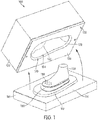
- FIG. 1 is a schematic isometric view of an embodiment of a fusing system 100.
- Fusing system 100 may be used to apply pressure and/or heat to materials on a three-dimensional last.
- fusing system 100 may be intended for use with various kinds of articles including articles of footwear and/or articles of apparel.
- Fusing system 100 may be used for a variety of purposes, including for example, fusing two or more materials together using pressure and/or heat.
- One such method for fusing materials together to form portions of an article of footwear is disclosed in Berend et al., now U.S. Patent Application Number 13/773,771, filed February 22, 2013 , and titled "Bottom Down Last for 3D Forming".
- fusing system 100 may be used to fuse materials together while the materials are disposed on a three-dimensional form, such as a last. This allows the materials to be joined in a manner that accommodates the contours of the final three-dimensional article.
- fusing system 100 may have other implementations.
- fusing system 100 may be used to transfer graphics from a transfer layer to a portion of an article using pressure and/or heat.
- a graphic transfer method that uses pressure and heat is disclosed in Hull, U.S. Patent Number 8,162,022, issued April 24, 2012 . Therefore, it will be understood that the fusing system 100 of the embodiments discussed below may be utilized for a variety of different purposes where it may be necessary to apply pressure and/or heat over portions of an article (i.e., footwear and/or apparel).
- the provisions described to facilitate fusing, bonding, graphic transfer, material shaping, as well as a variety of other functions may be useful with three-dimensional/contoured as well as substantially flat articles.
- a fusing system is used to apply pressure and/or heat to an article of footwear.
- a fusing system can be used with any kinds footwear including, but not limited to: hiking boots, soccer shoes, football shoes, sneakers, rugby shoes, basketball shoes, baseball shoes, running shoes as well as other kinds of shoes. While the embodiments in the figures show a single article, it will be understood that a fusing system could be used with two or more articles, including articles that make up a pair of footwear.
- a fusing system need not be limited to use with articles of footwear and the principles taught throughout this detailed description may be applied to additional articles as well. Generally, these principles could be applied to any article kinds of articles. Examples of articles that can be used with the fusing system include, but are not limited to: footwear, gloves, shirts, pants, socks, scarves, hats, jackets, as well as other articles. Other examples of articles that may be used include, but are not limited to: shin guards, knee pads, elbow pads, shoulder pads, as well as any other type of protective equipment. Additionally, in some embodiments, the article could be any other type of article, including, but not limited to: balls, bags, purses, backpacks, as well as other articles. Moreover, the article may be any article that can be worn or may be an article that is not generally worn.
- fusing system 100 may include a base member 110 and a corresponding upper member 120.
- Base member 110 generally comprises the lower part of fusing system 100, while upper member 120 may comprise the upper part of fusing system 100.
- base member 110 and upper member 120 may correspond in a manner that allows upper member 120 to interface with base member 110.
- upper member 120 may interface with base member 110 in a manner that provides a fluid tight seal between the two members.
- base member 110 may comprise a platform like portion.
- the geometry of base member 110 may be approximately rectangular, though in other embodiments the geometry could vary.
- base member 110 includes a raised central portion 112, which rises from a peripheral portion 114.
- base member 110 may further include an interface member 130.
- interface member 130 is disposed on raised central portion 112.
- Interface member 130 may be integrally formed with base member 110 or may be separably attached to base member 110.
- interface member 130 may include further provisions for connecting base member 110 and last member 150, which is discussed in further detail below.
- upper member 120 may comprise a block-like portion with a lower side 122 that confronts base member 110.
- lower side 122 may further include a central cavity 124 of upper member 120 that is concave with respect to a lower peripheral surface 126.
- the size and geometry of central cavity 124 may be such that central raised portion 112 of base member 110 fits into central cavity when upper member 120 is lowered onto base member 110.
- central cavity 124 can have any shape.
- central cavity 124 may have a substantially box-like shape so that central cavity 124 has a substantially constant depth.
- central cavity 124 could have an irregular shape.
- central cavity 124 could have a shape that corresponds approximately to the shape of a footwear last.
- central cavity 124 could have any other shape including, but not limited to: a rounded shape, a polyhedral shape, a regular shape, an irregular shape, a symmetric shape, an asymmetric shape as well as any other shape.
- upper member 120 may further include a pressing layer 160.
- pressing layer 160 may extend across a lower region 170 of central cavity 124. In some embodiments, pressing layer 160 may extend across the entirety of central cavity. Thus, in some embodiments, pressing layer 160 may generally separate a lower opening 172 of central cavity 124 from an interior chamber 174 (see FIG. 5 ). In some cases, interior chamber 174 may be bound by pressing layer 160 and interior cavity walls 176 of central cavity 124 (see FIG. 5 ).
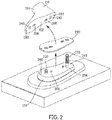
- FIG. 2 illustrates a schematic view of an embodiment of base member 110.
- fusing system 100 may be further associated with last member 150.
- last member 150 comprises a footwear last that has the approximate geometry of a foot.
- Last member 150 may be configured to receive portions of an article of footwear, such as a footwear upper, as well as materials used in the construction of the article of footwear (e.g., materials for making an upper).
- the current embodiment illustrates a footwear last
- other embodiments could incorporate lasts for other kinds of articles including any articles described above.
- a last could have the geometry of a head (or portion of a head) to accommodate the manufacturing of hats and/or other headwear.
- last member 150 may include various provisions to hold materials in place and/or heat materials disposed on last member 150.
- last member 150 could include one or more airflow holes. Airflow holes may be utilized in a variety of manners, including, providing suction along the surface of last member 150 to hold portions of material in place on last member 150. Additionally, in some cases, holes could be used to circulate air from inside last member 150 to the materials along the outer surface of last member 150. Such a use of airflow holes may allow heat emanating from elements inside last member 150 to be transferred efficiently to materials on last member 150.
- Embodiments may use any of the systems, components, devices and/or methods as disclosed in Fisher et al., now U.S. Patent Application Number 13/767,011, filed February 14, 2013 , and entitled "Last with Retractable Pins", hereafter referred to as the retractable pin case.
- some embodiments may incorporate airflow holes, other embodiments may not include any airflow holes.
- FIG. 1 illustrates a plurality of airflow holes 159.
- plurality of airflow holes 159 are localized in the toe region of last member 150.
- airflow holes can be arranged in any pattern and/or configuration over any portion of last member 150.
- Other embodiments, for example, could include a substantially even distribution of airflow holes over a majority of last member 150.
- Others could include sets of airflow holes selectively placed in various regions to facilitate suction as well as heating and/or cooling of various sections of material.
- last member 150 could include provisions for mechanically holding portions of material in place.
- some embodiments may incorporate one or more retractable pins that facilitate the alignment of material on last member 150.
- the retractable pins may retract inwardly into last member 150 once a component (such as pressing layer 160) contacts the pins, thereby reducing the tendency of the pins to puncture or otherwise damage the contacting component.
- the embodiments can use any of the retractable pin systems and/or configurations disclosed in the retractable pin case cited above.
- interface member 130 may provide a means of releasably connecting last member 150 to base member 110.
- interface member 130 includes first positioning pin 202 and second positioning pin 204.
- First positioning pin 202 and second positioning pin 204 are configured to insert into first receiving slot 206 and second receiving slot 208, respectively, which are located on bottom surface 152 of last member 150.
- first receiving slot 206 and second receiving slot 208 are sized and shaped so that first positioning pin 202 and second positioning pin 204 may be inserted into wider portions of first receiving slot 206 and second receiving slot 208, respectively, but may include more narrow portions that prevent the vertical release of first positioning pin 202 and second positioning pin 204.
- This arrangement allows last member 150 to be placed vertically down onto interface member 130 and then translated longitudinally to lock first positioning pin 202 and second positioning pin 204 in place relative to the vertical direction, thereby preventing unwanted removal of last member 150 from base member 110.
- the current embodiment uses two positioning pins, other embodiments could use one, two, three or more than three positioning pins. Moreover, the pins could be configured in any arrangement. Moreover, in other embodiments, any other kinds of fasteners known in the art are used to releasably secure a last member to interface member 130.
- last members to be releasably attached to a fusing system.
- two or more last members may be used in an interchangeable manner with a fusing system.
- some embodiments could utilize different interchangeable last members to accommodate differences in article orientations (i.e., left/right), article sizes (i.e., size 8, size 9, size 10, etc.) and/or article styles (i.e., low-top, high-top, etc.).
- fusing system 100 may include one or more thermal elements.
- thermal element refers to any component, device or system configured to change the thermal properties of a portion of fusing system 100.
- fusing system 100 comprises a first thermal element 220 and a second element 222 in the form of heating and cooling pipes.
- first thermal element 220 and second element 222 extend outwardly from base member 110, through interface member 130 and into last member 150. More specifically, first thermal element 220 extends through first interface hole 230 (see FIG. 5 ) and into first last hole 240. Likewise, second thermal element 222 extends through second interface hole 232 (see FIG. 5 ) and into second last hole 242.
- first thermal element 220 and second thermal element 222 may be inserted into corresponding holes of last member 150.
- first thermal element 220 and second thermal element 222 may act to heal and/or cool last member 150.
- first thermal element 220 and second thermal element 222 are airflow pipes that facilitate the transfer of hot and/or cool air from a heating/cooling source (not shown).
- fusing system 100 may include provisions for creating a vacuum within last member 150 and/or in the region surrounding last member 150.
- interface member 130 incorporates a first vacuum aperture 260 and a second vacuum aperture 262.
- First vacuum aperture 260 and second vacuum aperture 262 may be in fluid communication with a corresponding first vacuum channel 270 and second vacuum channel 272, respectively, of base member 110 (see FIG. 5 ).
- First vacuum channel 270 and second vacuum channel 272 may be further connect to a vacuum source (not shown), such as a vacuum pump.
- first vacuum aperture 260 and second vacuum aperture 262 may confront a first vacuum hole 280 and a second vacuum hole 282, respectively, disposed on bottom surface 152 of last member 150.
- first vacuum hole 280 and second vacuum hole 282 may be in fluid communication with first vacuum aperture 260 and second vacuum aperture 262.
- This arrangement allows a vacuum to be generated within the hollow interior 154 (see FIG. 5 ) of last member 150.
- this arrangement may create an inward pressure or suction along outer surface 156 of last member 150.
- first vacuum aperture 260 and/or second vacuum aperture 262 may be in fluid communication with the region between pressing layer 160 and base member 110, so that as a vacuum is generated, air within this region can be directly evacuated through first vacuum channel 270 and second vacuum channel 272.
- fusing system 100 may further include an intermediate layer 290.
- intermediate layer 290 may be a substantially thin layer of silicone.
- pressing layer 160 and intermediate layer 290 may act to substantially surround or enclose last member 150 (as well as materials disposed on last member 150). This arrangement may facilitate heating/cooling and/or may enhance the vacuum pressure applied around last member 150 by pressing layer 160.
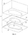
- FIG. 3 illustrate a schematic exploded isometric view of upper member 120 while FIG. 4 illustrates a schematic isometric top down view of pressing later 160.
- pressing layer 160 includes a substantially flat peripheral portion 302 and a contoured central portion 304. More specifically, the geometry of contoured central portion 304 is concave relative to an outward surface 310 (or lower surface) of pressing layer 160 (see FIG. 3 ) and convex relative to an inward surface 312 (or upper surface) of pressing layer 160 (see FIG. 4 ).
- a cavity 320 of contoured central portion 304 is configured to receive a last member (such as last member 150).
- contoured central portion 304 has a geometry that approximates the top of a footwear last.
- Contoured central portion 304 may include a forefoot portion 330, a midfoot portion 332, a heel portion 334 and an ankle portion 336, which all generally correspond to regions of a footwear last, such as last member 150.
- this contoured shaped is maintained as long as pressing layer 160 is not subjected to any external forces, such as various air or other fluid pressures.
- pressing layer 160 may be made of a substantially flexible, elastic and/or deformable material.
- pressing layer 160 may be configured to stretch, bend, twist, and/or otherwise flex or deform in a manner that differs from the default geometry shown in FIG. 4 .
- the degree of flexibility can be selected so that pressing layer 160 can flex around last member 150 when subjected to various pressures within fusing system 100.
- pressing layer 160 may flex enough to conform tightly to the shape of last member 150.
- pressing layer 160 may return to the default geometry once again.
- pressing layer 160 could comprise a variety of different materials.
- pressing layer 160 may comprise a layer of silicone material.
- other embodiments could utilize any other materials that are substantially flexible and/or deformable.
- the type of material used for pressing layer 160 may be selected according to various factors including desired flexibility, desired elasticity, desired thermal conduction properties, desired durability as well as possibly other factors.
- upper member 120 may comprise a body portion 360 and a lower frame portion 362.
- Peripheral portion 302 of pressing layer 160 may be pressed between body portion 360 and lower frame portion 362.
- the fastening of lower frame portion 362 to body portion 360 can be accomplished using any kinds of fasteners, including, but not limited to: screws, bolts, nails, rivets as well as any other kinds of fasteners known in the art.
- FIGS. 3 and 4 include a pressing layer shaped to accommodate a last member of a predetermined shape.
- the geometry of a pressing layer may vary to accommodate last members of different geometries.
- lasts corresponding to high-tops and low-tops may require the use of pressing layers having corresponding geometries.
- embodiments using a last for other kinds of articles i.e., a head-shaped last for a hat or a torso-shaped last for a shirt
- FIG. 5 illustrates a cross-sectional view of various components of fusing system 100.
- pressing layer 160 comprises various contours that approximately correspond with various contoured portions of last member 150.
- pressing layer 160 is pre-shaped or pre-configured to associate with last member 150.
- a pressing layer with a pre-shaped geometry may help reduce the tendency of the pressing layer to tug, pull or otherwise apply undesirable forces to material layers as the upper member is lowered to the base member.
- a pre-shaped geometry may reduce ripping, tearing or other undesired permanent deformations of the pressing layer prior to the application of the vacuum to deform the pressing layer to the last member.
- FIGS. 6 through 13 illustrate an exemplary method of using fusing system 100 to form an upper for an article of footwear, in which the resulting upper is formed from at least a base layer and two trim layers.
- the resulting upper is formed from at least a base layer and two trim layers.
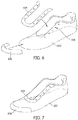
- FIGS. 6 and 7 illustrate schematic isometric views of materials that may be used with fusing system 100 in order to create an upper for an article of footwear.
- a base layer 602 may be associated with a first trim layer 604 and a second trim layer 606.
- first trim layer 604 may be configured to cover and/or reinforce the region associated with eyelets 608 of base layer 602.
- Second trim layer 606 may be associated with a toe portion of base layer 602.
- two trim layers are shown here, however in other embodiments any number of layers could be used.
- the layers may be trim layers, or any other kinds of layers which may improve functionality and/or modify the overall material characteristics of the resulting upper.
- first trim layer 604 and/or second trim layer 606 may be temporarily fixed in place on base layer 602.
- first trim layer 604 and/or second trim layer 606 may be temporarily attached to base layer 602 using, but not limited to, any of the following methods: temporary adhesives, welding (including ultrasonic welding), various kinds of fasteners (i.e., pins, clips, etc.), as well as possibly other provisions.
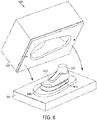
- FIG. 8 illustrates a schematic isometric view of fusing system 100, in which base layer 602, first trim layer 604 and second trim layer 606 have all been placed onto last member 150. At this point, upper member 120 may be lowered onto base member 110.
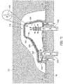
- FIG. 9 shows a cross-sectional view of fusing system 100 once upper member 120 has been lowered onto base member 110.
- pressing layer 160 may initially be spaced apart from base layer 602, first trim layer 604 and second trim layer 606. In some cases, this arrangement may help reduce the tendency of pressing layer 160 to cause one or layers to be misaligned prior to the application of a vacuum. In other embodiments, pressing layer 160 may be in contact with one or more of these layers.
- vacuum pressure can be used to pull pressing layer 160 tightly against last member 150 as well as base layer 602, first trim layer 604 and second trim layer 606.
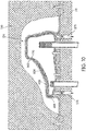
- a vacuum (indicated schematically by arrows within first vacuum channel 270 and second vacuum channel 272) created between pressing layer 160 and base member 110 may cause pressing layer 160 to conform to the contours of last member 150.
- heat may also be applied using first thermal element 220 and second thermal element 222. In FIG. 11 the heating of interior 154 of last member 150 due to the inflow of hot air is indicated schematically by thermometer 650. The resulting heat and pressure may cause first trim layer 604 and second trim layer 606 to be permanently bonded, or fused, to base layer 602.
- the pressure of cavity 174 could also be adjusted.
- the pressure of cavity 174 could be increased using an external pressure source.
- pressing layer 160 may be further pressed against last member 150 and corresponding layers of material.
- this increase in pressure in cavity 174 may increase the force with which pressing layer 160 is applied across the surface of last member 150 and the overlying materials.
- the embodiments may use any of the systems, devices, components and/or methods for applying external pressure forces to a flexible membrane in a cavity that are disclosed in Fisher et al., now U.S. Patent Application Number 13/773,744, filed February 22, 2013 and titled "System and Method for Applying Heat and Pressure to Three-Dimensional Articles".
- the vacuum pressure may be released so that pressing layer 160 returns to a default state (i.e., default geometry).
- cool air can be circulated within last member 150 through first thermal element 220 and second thermal element 222.
- the cooling of interior 154 of last member 150 is indicated schematically by thermometer 650.
- upper member 120 may be lifted from base member 110 so that the resulting upper 700 can then be removed from last member 150.
- Upper 700 may comprise permanently fused layers that may remain attached under various types of stresses applied to upper 700 when upper 700 is worn.
- upper 700 may be further associated with a sole structure or similar component in order to create a finished article of footwear.
- FIG. 14 illustrates an alternative pressing layer geometry that may be used with a last for forming hats.
- first pressing layer 802 may have a geometry that approximately corresponds with the geometry of last member 804, which is last for making hats.
- hat 810 may be fused with a panel of material 812 by placed hat 810 onto last member 804 and pressing it with pressing layer 802 using the previously described methods and systems.
Landscapes
- Engineering & Computer Science (AREA)
- Mechanical Engineering (AREA)
- Footwear And Its Accessory, Manufacturing Method And Apparatuses (AREA)
- Blow-Moulding Or Thermoforming Of Plastics Or The Like (AREA)
Claims (11)
- Ein System (100) zum Herstellen von Artikeln, das Folgendes umfasst:ein oberes Element (120), das einen Hohlraum (124) aufweist, wobei ferner dem oberen Element einer Anpressschicht (160) zugeordnet ist, die sich in den Hohlraum erstreckt;ein Basiselement (110), das konfiguriert ist, um mit dem oberen Element verbunden zu werden, wobei das Verbinden des oberen Elements mit dem Basiselement eine Abdichtung in einem Bereich zwischen der Anpressschicht und dem Basiselement bereitstellt;ein Schnittstellenelement (130), das auf dem Basiselement angeordnet ist;ein Leistenelement (150), das lösbar am Schnittstellenelement befestigt ist, wobei das Leistenelement ein Schuhwerk umfasst, das die ungefähre Geometrie eines Fußes aufweist, wobei das Leistenelement einen hohlen Innenraum (154) aufweist;wobei das Schnittstellenelement einen ersten Positionierstift (202) beinhaltet, der konfiguriert ist, um in einen ersten Aufnahmeschlitz (206) eingesetzt zu werden, der sich auf einer Unterseite (152) des Leistenelements befindet;wobei sich ein erstes Thermoelement (220) ausgehend vom Basiselement, durch das Schnittstellenelement und in das Leistenelement nach außen erstreckt;wobei die Anpressschicht einen konturierten Abschnitt (304) beinhaltet; undwobei die Anpressschicht verwendet werden kann, um Druck auf mindestens zwei Materialien auszuüben, die zwischen der Anpressschicht und dem Basiselement angeordnet sind.
- Das System nach Anspruch 1, wobei das Schnittstellenelement auf einem erhöhten zentralen Abschnitt des Basiselements angeordnet ist, wobei das Schnittstellenelement einen zweiten Positionierungsstift beinhaltet, wobei der erste Positionierungsstift und der zweite Positionierungsstift konfiguriert sind, um jeweils in den ersten Aufnahmeschlitz bzw. einen zweiten Aufnahmeschlitz eingesetzt zu werden, wobei der zweite Aufnahmeschlitz auf der Unterseite des Leistenelements angeordnet ist, wobei das System ferner ein zweites Thermoelement umfasst, das sich ausgehend vom Basiselement über das Schnittstellenelement bis zum Leistenelement nach außen erstreckt.
- Das System nach Anspruch 2, wobei der konturierte Abschnitt eine Form aufweist, die einem Schuhwerk-Leisten entspricht.
- Das System nach Anspruch 2, wobei das Schnittstellenelement eine erste Vakuumöffnung und eine zweite Vakuumöffnung beinhaltet, wobei die erste Vakuumöffnung in Fluidverbindung mit einem ersten Vakuumkanal des Basiselements steht und die zweite Vakuumöffnung in Fluidverbindung mit einem zweiten Vakuumkanal des Basiselements steht, und wobei mindestens eine der ersten Vakuumöffnung und der zweiten Vakuumöffnung in Fluidverbindung mit dem Bereich zwischen der Anpressschicht und dem Basiselement steht, und wobei der erste Vakuumkanal und der zweite Vakuumkanal konfiguriert sind, um Luft aus dem Bereich zwischen der Anpressschicht und dem Basiselement zu evakuieren.
- Das System nach Anspruch 4, wobei das Leistenelement lösbar am Basiselement befestigt ist.
- Das System nach Anspruch 2, wobei die Anpressschicht zwischen einem Körperabschnitt und einem unteren Rahmenabschnitt des oberen Elements an Ort und Stelle gehalten wird.
- Das System nach Anspruch 2, wobei der erste Aufnahmeschlitz und der zweite Aufnahmeschlitz jeweils einen breiteren Abschnitt und einen schmalen Abschnitt beinhalten, und wobei der schmale Abschnitt konfiguriert ist, um ein vertikales Lösen des ersten Positionierstiftes und des zweiten Positionierstiftes zu verhindern.
- Das System nach Anspruch 2, das ferner eine Zwischenschicht umfasst, die zwischen dem Leistenelement und dem Schnittstellenelement angeordnet ist.
- Das System nach Anspruch 8, wobei die Zwischenschicht eine Schicht aus Silikon umfasst.
- Das System nach Anspruch, wobei die erste Vakuumöffnung einem ersten Vakuumloch gegenüberliegt, das auf der Unterseite des Leistenelements angeordnet ist, und wobei die zweite Vakuumöffnung einem zweiten Vakuumloch gegenüberliegt, das auf der Unterseite des Leistenelements angeordnet ist.
- Das System nach Anspruch 10, wobei die Vakuumöffnungen eins und zwei, die Vakuumlöcher eins und zwei und die Vakuumkanäle eins und zwei erlauben, im hohlen Innenraum des Leistenelements ein Vakuum zu erzeugen.
Applications Claiming Priority (4)
| Application Number | Priority Date | Filing Date | Title |
|---|---|---|---|
| US13/773,729 US9585438B2 (en) | 2013-02-22 | 2013-02-22 | System and method for forming an article |
| EP14723517.0A EP2931077B1 (de) | 2013-02-22 | 2014-02-20 | System und verfahren zur bildung eines artikels |
| PCT/US2014/017240 WO2014130599A2 (en) | 2013-02-22 | 2014-02-20 | System and method for forming an article |
| EP17001168.8A EP3266330B1 (de) | 2013-02-22 | 2014-02-20 | System und verfahren zur bildung eines artikels |
Related Parent Applications (2)
| Application Number | Title | Priority Date | Filing Date |
|---|---|---|---|
| EP17001168.8A Division EP3266330B1 (de) | 2013-02-22 | 2014-02-20 | System und verfahren zur bildung eines artikels |
| EP14723517.0A Division EP2931077B1 (de) | 2013-02-22 | 2014-02-20 | System und verfahren zur bildung eines artikels |
Publications (2)
| Publication Number | Publication Date |
|---|---|
| EP3415030A1 EP3415030A1 (de) | 2018-12-19 |
| EP3415030B1 true EP3415030B1 (de) | 2019-12-18 |
Family
ID=50693948
Family Applications (3)
| Application Number | Title | Priority Date | Filing Date |
|---|---|---|---|
| EP17001168.8A Active EP3266330B1 (de) | 2013-02-22 | 2014-02-20 | System und verfahren zur bildung eines artikels |
| EP18187163.3A Active EP3415030B1 (de) | 2013-02-22 | 2014-02-20 | System zur bildung eines artikels |
| EP14723517.0A Active EP2931077B1 (de) | 2013-02-22 | 2014-02-20 | System und verfahren zur bildung eines artikels |
Family Applications Before (1)
| Application Number | Title | Priority Date | Filing Date |
|---|---|---|---|
| EP17001168.8A Active EP3266330B1 (de) | 2013-02-22 | 2014-02-20 | System und verfahren zur bildung eines artikels |
Family Applications After (1)
| Application Number | Title | Priority Date | Filing Date |
|---|---|---|---|
| EP14723517.0A Active EP2931077B1 (de) | 2013-02-22 | 2014-02-20 | System und verfahren zur bildung eines artikels |
Country Status (5)
| Country | Link |
|---|---|
| US (2) | US9585438B2 (de) |
| EP (3) | EP3266330B1 (de) |
| KR (2) | KR101804031B1 (de) |
| CN (2) | CN107048600B (de) |
| WO (1) | WO2014130599A2 (de) |
Families Citing this family (40)
| Publication number | Priority date | Publication date | Assignee | Title |
|---|---|---|---|---|
| US9351540B2 (en) | 2013-02-14 | 2016-05-31 | Nike, Inc. | Last with retractable pins |
| US9713361B2 (en) | 2013-02-22 | 2017-07-25 | Nike, Inc. | Bottom-down last for 3D forming |
| US9259877B2 (en) | 2013-02-22 | 2016-02-16 | Nike, Inc. | System and method for applying heat and pressure to three-dimensional articles |
| CA2888418C (en) * | 2014-04-15 | 2024-01-09 | Sport Maska Inc. | Skate and method of manufacture |
| US9789644B2 (en) | 2014-11-13 | 2017-10-17 | Adidas Ag | Methods of vacuum forming articles of wear |
| TWI556757B (zh) * | 2015-01-16 | 2016-11-11 | 耐基創新公司 | 形狀記憶聚合物鞋類鞋楦系統、自形狀記憶聚合物鞋類鞋楦預成形體形成鞋類鞋楦的方法、使用單一形狀記憶聚合物鞋類鞋楦預成形體製作各種不同形狀及大小的鞋類的方法 |
| US11297902B2 (en) | 2016-10-03 | 2022-04-12 | Adidas Ag | Laceless shoe |
| US11350701B2 (en) | 2015-10-09 | 2022-06-07 | Adidas Ag | Laceless shoe |
| DE102015219614B4 (de) | 2015-10-09 | 2025-06-18 | Adidas Ag | Schnürsenkelloser Schuh |
| DE102015219636B4 (de) | 2015-10-09 | 2023-11-23 | Adidas Ag | Herstellungsverfahren zum Beschichten eines Gewebes mit einer dreidimensionalen Form |
| US11758979B2 (en) | 2015-10-09 | 2023-09-19 | Adidas Ag | Shoe |
| US12232564B2 (en) | 2015-11-09 | 2025-02-25 | Under Armour, Inc. | Method of forming an article of footwear |
| ITUB20155474A1 (it) * | 2015-11-11 | 2017-05-11 | Nike Innovate Cv | Apparecchiatura, e relativo procedimento, per il trattamento termico di calzature, in particolare calzature sportive |
| DE102015224885B4 (de) | 2015-12-10 | 2024-11-07 | Adidas Ag | Verfahren für die Platzierung von Patches und hergestellte Artikel |
| GB2545469A (en) * | 2015-12-17 | 2017-06-21 | C & J Clark Int Ltd | Manufacturing articles of footwear |
| US10905200B2 (en) * | 2015-12-29 | 2021-02-02 | Nike, Inc. | Footwear component manufacturing fixture |
| TWI590944B (zh) * | 2016-08-19 | 2017-07-11 | 捷欣企業股份有限公司 | 立體複合材成型方法 |
| EP3981281B1 (de) | 2016-11-09 | 2024-03-27 | NIKE Innovate C.V. | Artikel, der ein aufgeschmolzenes material und ein gedrucktes element enthält, und sein herstellungsverfahren |
| DE102016224240B4 (de) * | 2016-12-06 | 2022-02-03 | Adidas Ag | Verfahren zur Herstellung eines vollständig geformten Oberteils |
| EP3335876A1 (de) * | 2016-12-15 | 2018-06-20 | Chaei Hsin Enterprise Co., Ltd. | Verfahren zur herstellung eines dreidimensionalen verbundwerkstoffs |
| JP2018094836A (ja) * | 2016-12-15 | 2018-06-21 | 捷欣企業股▲ふん▼有限公司 | 立体複合材の成型方法 |
| EP3589150B1 (de) * | 2017-02-28 | 2023-05-10 | Under Armour, Inc. | Schuhoberteil und schuhwerk mit dem schuhoberteil |
| CN110799055B (zh) | 2017-05-08 | 2023-10-31 | 耐克创新有限合伙公司 | 模块化鞋类物品和制造定制的鞋类物品的方法 |
| TW201906556A (zh) * | 2017-07-06 | 2019-02-16 | 捷欣企業股份有限公司 | 鞋材的製備方法 |
| MX2020004296A (es) | 2017-10-31 | 2020-11-11 | World Emblem Int Inc | Sistema y metodo de decoracion de gorra o sombrero. |
| IT201800003730A1 (it) * | 2018-03-19 | 2019-09-19 | Macpi S P A Pressing Div | Metodo per la formatura tridimensionale di una tomaia di una calzatura |
| CN108514183A (zh) * | 2018-03-26 | 2018-09-11 | 中山市大广鞋材有限公司 | 一种水平鞋面的装饰工艺 |
| CN108433246A (zh) * | 2018-03-26 | 2018-08-24 | 中山市大广鞋材有限公司 | 一种立体鞋面的装饰工艺 |
| TWI674967B (zh) * | 2018-04-02 | 2019-10-21 | 捷欣企業股份有限公司 | 鞋件製造方法及其製造系統 |
| TWI722417B (zh) | 2018-04-25 | 2021-03-21 | 荷蘭商耐克創新有限合夥公司 | 製備待熱成形物品的系統及方法 |
| TWI809379B (zh) | 2018-04-25 | 2023-07-21 | 荷蘭商耐克創新有限合夥公司 | 熱成形物品的系統 |
| EP3843579B1 (de) | 2018-08-28 | 2022-12-14 | NIKE Innovate C.V. | Verfahren zur formung einer schuhzwischensohle |
| IT201800011142A1 (it) * | 2018-12-17 | 2020-06-17 | Robot System Automation S R L | Forma per la produzione di calzature |
| US12232565B2 (en) * | 2019-02-26 | 2025-02-25 | Ecco Sko A/S | Method of manufacturing a footwear |
| CN110367650B (zh) * | 2019-08-12 | 2024-09-20 | 维度一元认知科技(东莞)有限公司 | 压鞋机 |
| IT202000026314A1 (it) * | 2020-11-04 | 2022-05-04 | Scarpa Calzaturificio Spa | Macchina per la lavorazione di tomaie per calzature e relativo metodo di funzionamento |
| IT202100009821A1 (it) * | 2021-04-19 | 2022-10-19 | Denny VALENTINI | Dispositivo di supporto per il trattamento termico di una tomaia |
| US11701823B1 (en) | 2021-05-19 | 2023-07-18 | Under Armour, Inc. | Method of making footwear components |
| US11707104B1 (en) * | 2022-03-03 | 2023-07-25 | Cricut, Inc. | Heat press apparatuses, systems, and methods |
| EP4686427A1 (de) * | 2024-08-02 | 2026-02-04 | Irocol S.r.l. | System zum automatischen pressen einer schuhsohle und eines obermaterials |
Family Cites Families (82)
| Publication number | Priority date | Publication date | Assignee | Title |
|---|---|---|---|---|
| US1731024A (en) * | 1929-10-08 | Shoe-pressing device | ||
| US1365267A (en) * | 1918-09-05 | 1921-01-11 | Clifford H Oakley | Method of and apparatus for making shoes |
| US1592722A (en) * | 1924-03-04 | 1926-07-13 | Daniel G Carter | Shoe last |
| US1703614A (en) * | 1926-12-09 | 1929-02-26 | Witt William J De | Pull-over and process of making the same |
| US1925899A (en) * | 1927-11-10 | 1933-09-05 | Hood Rubber Co Inc | Apparatus for manufacturing footwear |
| US1904851A (en) * | 1928-04-24 | 1933-04-18 | Compo Shoe Machinery Corp | Method of making footwear |
| GB443696A (en) | 1935-10-17 | 1936-03-04 | Konstruktions & Patente A G | Apparatus for veneering and particularly for veneering irregularly formed pieces of work |
| US2113802A (en) * | 1937-03-22 | 1938-04-12 | Valdiserri Herman | Shoe shank cementing press |
| US2229085A (en) * | 1937-06-11 | 1941-01-21 | Hoza John | Vulcanizing apparatus |
| GB494885A (en) | 1937-09-22 | 1938-11-03 | Johann Palfi | Improvements in or relating to pressing, bending or veneering wood |
| US2301785A (en) * | 1939-10-12 | 1942-11-10 | Marx Guilherme Siegfried | Apparatus for the manufacture of shoes |
| US2247818A (en) * | 1939-11-02 | 1941-07-01 | Universal Plasties Corp | Shoe last |
| US2443877A (en) * | 1946-09-23 | 1948-06-22 | Joyce Inc | Apparatus for manufacturing footwear utilizing sub-assemblies and applying the same directly to the lasts |
| CH285223A (de) | 1950-10-24 | 1952-08-31 | Ag Ulrich Steinemann | Verfahren zum Furnieren und Einrichtung an Furnierpressen. |
| US2641004A (en) * | 1950-12-26 | 1953-06-09 | David V Whiting | Method for producing knitted shoe uppers of shrinkable yarn |
| US2878523A (en) * | 1954-01-18 | 1959-03-24 | Int Vulcanizing Corp | Method of making rubber shoes |
| US2907058A (en) * | 1956-12-21 | 1959-10-06 | Dejo Inc | Shoes and method of making the same |
| US2996739A (en) | 1957-12-27 | 1961-08-22 | Bata Shoe Company Of Canada Lt | Shoe pressing machine |
| US3141183A (en) * | 1959-07-01 | 1964-07-21 | Ralphs Engineering Company Ltd | Machines for lasting footwear |
| US3102286A (en) * | 1961-04-20 | 1963-09-03 | Pentron Electronics Corp | Apparatus for thermoplastic sealing |
| US3160899A (en) * | 1961-05-08 | 1964-12-15 | Bille Mario | Device for glueing the upper to soles of shoes |
| FR1484462A (de) | 1965-06-25 | 1967-09-15 | ||
| US3349417A (en) * | 1965-08-27 | 1967-10-31 | Compo Shoe Machinery Corp | Method of mulling and heat-setting in shoe manufacture |
| US3501793A (en) * | 1966-05-06 | 1970-03-24 | Genesco Inc | Shoe last |
| US3390411A (en) * | 1966-06-07 | 1968-07-02 | Compo Shoe Machinery Corp | Lasting machine with adhesive applicator |
| US3512197A (en) * | 1968-04-24 | 1970-05-19 | Harold S Carr Sr | Shoe making machine |
| US3803655A (en) | 1971-03-19 | 1974-04-16 | R White | Apparatus for manufacturing leather goods and the like |
| US3855657A (en) * | 1973-11-12 | 1974-12-24 | G Mazzotta | Shoe moulds |
| US3938211A (en) * | 1974-11-27 | 1976-02-17 | Albert Warner Armstrong | Fluid lasting of shoes and similar operations |
| GB1485891A (en) * | 1975-01-22 | 1977-09-14 | Bata Dev Ltd | Apparatus for shaping flexible sheet material into footwear uppers |
| CH616094A5 (en) | 1977-03-25 | 1980-03-14 | Jeger M Eisen Metall Und Appar | Apparatus for the vacuum forming of flexible materials |
| NL7714472A (en) | 1977-12-28 | 1979-07-02 | Nl Schoen En Lederfabrieken Ba | Shoe sole and upper fitting process - by fixing inner sole and upper on last, introducing dome membrane and applying pressure in cage chamber and vacuum in last chamber |
| GB2028101B (en) * | 1978-08-19 | 1982-06-16 | British United Shoe Machinery | Apparatus for shaping laminated shoe uppers |
| US4290838A (en) | 1978-12-04 | 1981-09-22 | General Dynamics, Pomona Division | Method for vacuum lamination of flex circuits |
| FR2562770B1 (fr) | 1984-04-17 | 1986-09-12 | Rigo Expl Ets | Procede et dispositif de montage d'une tige de chaussure sur une forme |
| US4660242A (en) | 1986-03-24 | 1987-04-28 | International Shoe Machine Corporation | Activator |
| AT386731B (de) | 1986-10-21 | 1988-10-10 | Tyrolia Freizeitgeraete | Verfahren zum herstellen eines schuhes |
| IT209639Z2 (it) | 1986-10-23 | 1988-10-24 | S I C C Soc Ind Comm Casalingh | Tappo per bottiglie, particolarmente bottiglie termoisolanti. |
| US5108532A (en) | 1988-02-02 | 1992-04-28 | Northrop Corporation | Method and apparatus for shaping, forming, consolidating and co-consolidating thermoplastic or thermosetting composite products |
| CA2000090A1 (en) | 1988-10-03 | 1990-04-03 | John J. Curley, Jr. | Heat embossed shoes |
| US4964229A (en) | 1989-02-03 | 1990-10-23 | Sport Maska, Inc. | Method and apparatus for vacuum molding multi-layer footwear |
| JPH0717043B2 (ja) | 1990-04-24 | 1995-03-01 | 東レ株式会社 | 食品包装用袋 |
| US6299817B1 (en) | 1990-10-16 | 2001-10-09 | Kevin G. Parkinson | Method for seamless construction of molded elastomer products |
| US5129813A (en) | 1991-02-11 | 1992-07-14 | Shepherd G Maury | Embossed vacuum bag, methods for producing and using said bag |
| JP3092992B2 (ja) | 1991-08-29 | 2000-09-25 | 大日本印刷株式会社 | 真空プレス積層成形方法 |
| US5275775A (en) * | 1991-10-21 | 1994-01-04 | Riecken George C | Method for making an insole |
| US5296182A (en) | 1992-05-28 | 1994-03-22 | Creme Art Corporation | Method for making formed laminate |
| BE1006215A6 (fr) | 1992-09-02 | 1994-06-07 | Jonathan Car Styling Internati | Recouvrement de bois de placage ou de tissu en automobiles. |
| US5940991A (en) * | 1995-04-07 | 1999-08-24 | Performance Materials Corporation | Non-planar article formed from thermoplastic composite material and method of forming non-planar article |
| US5885500A (en) | 1995-12-20 | 1999-03-23 | Nike, Inc. | Method of making an article of footwear |
| JP3887665B2 (ja) | 1996-02-02 | 2007-02-28 | 株式会社タイカ | 立体形状物品に対する凹凸成形方法並びにこの方法に使用される自変形成形型 |
| US6007748A (en) * | 1997-10-16 | 1999-12-28 | Krajcir; Dezi Anthony | Production of molded laminated articles, particularly soles for footwear |
| US6805825B1 (en) * | 1997-12-22 | 2004-10-19 | Macleod Norman William | Manufacture of footwear |
| JPH11192105A (ja) * | 1997-12-26 | 1999-07-21 | Masanobu Furuhashi | 靴の中底及び木型並びに靴の製造法 |
| KR200220813Y1 (ko) | 1998-05-22 | 2001-09-17 | 김재용 | 신발제조용압착기 |
| US6849141B2 (en) | 1998-09-15 | 2005-02-01 | Batesville Services, Inc. | Casket lid and method of making same |
| CA2256917A1 (en) | 1998-12-22 | 2000-06-22 | Bauer Nike Hockey Inc. | Piece of footwear |
| US6558784B1 (en) | 1999-03-02 | 2003-05-06 | Adc Composites, Llc | Composite footwear upper and method of manufacturing a composite footwear upper |
| CN2368328Y (zh) * | 1999-05-07 | 2000-03-15 | 张良村 | 鞋子真空冷冻定型机 |
| IT1318737B1 (it) | 2000-08-07 | 2003-09-10 | Nextec Srl | Procedimento per impermeabilizzare semilavorati di calzature, capi edaccessori di abbigliamento, nonche' semilavorati ottenuti con tale |
| ITBO20010104A1 (it) | 2001-02-27 | 2002-08-27 | Mario Ciucani | Metodo per l'incollaggio di un fondo ad una relativa tomaia di calzatura |
| ITBO20020264A1 (it) * | 2002-05-07 | 2003-11-07 | Mario Ciucani | Metodo per l'incollaggio di un fondo ad una relativa tomaia di calzatura |
| JP3865307B2 (ja) | 2002-09-17 | 2007-01-10 | 美津濃株式会社 | シューズおよびその製造方法 |
| ITMI20031258A1 (it) | 2003-06-20 | 2004-12-21 | Nextec Srl | Procedimento e macchina per impermeabilizzare semilavorati di calzature, capi ed accessori di abbigliamento, e semilavorati ottenuti con tale procedimento o macchina. |
| KR100627143B1 (ko) | 2004-12-31 | 2006-09-25 | 박장원 | 입체형 신발 갑피용 가교발포 성형체 및 그 제조방법 |
| KR100618383B1 (ko) | 2005-02-07 | 2006-08-30 | 박장원 | 입체형 신발 갑피용 가교발포 성형체의 제조방법 |
| US7556492B2 (en) * | 2005-11-09 | 2009-07-07 | Nike, Inc. | Footwear mold heating system and method |
| US7430816B1 (en) * | 2006-08-09 | 2008-10-07 | Lozenski Matthew J | Footwear dryer and sanitizer apparatus |
| EP1894717B1 (de) | 2006-08-29 | 2009-06-17 | Robert Bürkle GmbH | Presse und Verfahren zum Laminieren plattenförmiger Werkstücke mittels Druck und Wärme |
| CN200944888Y (zh) * | 2006-09-27 | 2007-09-12 | 东莞长安霄边兴鹏鞋厂 | 内外腰侧压机 |
| US20080172906A1 (en) | 2007-01-19 | 2008-07-24 | Wern-Shiamg Jou | Skate boot |
| US8544191B2 (en) | 2007-04-10 | 2013-10-01 | Reebok International Limited | Smooth shoe uppers and methods for producing them |
| DE102008044862A1 (de) | 2008-08-28 | 2010-03-04 | Robert Bürkle GmbH | Verfahren und Laminierpresse zum Laminieren von Werkstücken |
| US8162022B2 (en) | 2008-10-03 | 2012-04-24 | Nike, Inc. | Method of customizing an article and apparatus |
| US7950432B2 (en) * | 2009-06-24 | 2011-05-31 | Nike, Inc. | Method of customizing an article and apparatus including an inflatable member |
| US8321984B2 (en) | 2009-10-21 | 2012-12-04 | Nike, Inc. | Composite shoe upper and method of making same |
| CN201536697U (zh) * | 2009-11-06 | 2010-08-04 | 张聪儒 | 鞋体压模机 |
| WO2011082275A1 (en) | 2009-12-30 | 2011-07-07 | Li Ning Sports Usa, Inc. | Lastless, molded footwear and methods of construction |
| US8572786B2 (en) | 2010-10-12 | 2013-11-05 | Reebok International Limited | Method for manufacturing inflatable bladders for use in footwear and other articles of manufacture |
| US9161592B2 (en) | 2010-11-02 | 2015-10-20 | Nike, Inc. | Fluid-filled chamber with a stacked tensile member |
| US9713361B2 (en) * | 2013-02-22 | 2017-07-25 | Nike, Inc. | Bottom-down last for 3D forming |
| US9259877B2 (en) * | 2013-02-22 | 2016-02-16 | Nike, Inc. | System and method for applying heat and pressure to three-dimensional articles |
-
2013
- 2013-02-22 US US13/773,729 patent/US9585438B2/en active Active
-
2014
- 2014-02-20 EP EP17001168.8A patent/EP3266330B1/de active Active
- 2014-02-20 CN CN201710368032.0A patent/CN107048600B/zh active Active
- 2014-02-20 WO PCT/US2014/017240 patent/WO2014130599A2/en not_active Ceased
- 2014-02-20 EP EP18187163.3A patent/EP3415030B1/de active Active
- 2014-02-20 CN CN201480009590.2A patent/CN105072943B/zh active Active
- 2014-02-20 KR KR1020157022999A patent/KR101804031B1/ko active Active
- 2014-02-20 KR KR1020177033849A patent/KR101874767B1/ko active Active
- 2014-02-20 EP EP14723517.0A patent/EP2931077B1/de active Active
-
2017
- 2017-02-28 US US15/444,642 patent/US10897962B2/en active Active
Non-Patent Citations (1)
| Title |
|---|
| None * |
Also Published As
| Publication number | Publication date |
|---|---|
| CN107048600B (zh) | 2020-10-09 |
| KR20170132353A (ko) | 2017-12-01 |
| KR101804031B1 (ko) | 2017-12-01 |
| CN107048600A (zh) | 2017-08-18 |
| EP3266330B1 (de) | 2018-08-29 |
| KR20150110746A (ko) | 2015-10-02 |
| US10897962B2 (en) | 2021-01-26 |
| KR101874767B1 (ko) | 2018-07-04 |
| US20170164692A1 (en) | 2017-06-15 |
| EP3266330A1 (de) | 2018-01-10 |
| US20140237738A1 (en) | 2014-08-28 |
| EP3415030A1 (de) | 2018-12-19 |
| EP2931077A2 (de) | 2015-10-21 |
| EP2931077B1 (de) | 2017-08-09 |
| US9585438B2 (en) | 2017-03-07 |
| WO2014130599A3 (en) | 2014-10-23 |
| CN105072943B (zh) | 2017-06-09 |
| WO2014130599A2 (en) | 2014-08-28 |
| CN105072943A (zh) | 2015-11-18 |
Similar Documents
| Publication | Publication Date | Title |
|---|---|---|
| US10897962B2 (en) | System and method for forming an article | |
| EP2925180B1 (de) | Leisten mit nach unten zeigender oberseite zur 3d-formung | |
| US10582742B2 (en) | Last with retractable pins | |
| US9936766B2 (en) | Fluid-filled structure | |
| US9161592B2 (en) | Fluid-filled chamber with a stacked tensile member | |
| KR102567125B1 (ko) | 신발류 물품 및 신발류 물품의 제조 방법 | |
| CN103763961A (zh) | 具有区域性造型的鞋面及其制造 |
Legal Events
| Date | Code | Title | Description |
|---|---|---|---|
| PUAI | Public reference made under article 153(3) epc to a published international application that has entered the european phase |
Free format text: ORIGINAL CODE: 0009012 |
|
| STAA | Information on the status of an ep patent application or granted ep patent |
Free format text: STATUS: THE APPLICATION HAS BEEN PUBLISHED |
|
| AC | Divisional application: reference to earlier application |
Ref document number: 3266330 Country of ref document: EP Kind code of ref document: P Ref document number: 2931077 Country of ref document: EP Kind code of ref document: P |
|
| AK | Designated contracting states |
Kind code of ref document: A1 Designated state(s): AL AT BE BG CH CY CZ DE DK EE ES FI FR GB GR HR HU IE IS IT LI LT LU LV MC MK MT NL NO PL PT RO RS SE SI SK SM TR |
|
| STAA | Information on the status of an ep patent application or granted ep patent |
Free format text: STATUS: REQUEST FOR EXAMINATION WAS MADE |
|
| 17P | Request for examination filed |
Effective date: 20190606 |
|
| GRAP | Despatch of communication of intention to grant a patent |
Free format text: ORIGINAL CODE: EPIDOSNIGR1 |
|
| RBV | Designated contracting states (corrected) |
Designated state(s): AL AT BE BG CH CY CZ DE DK EE ES FI FR GB GR HR HU IE IS IT LI LT LU LV MC MK MT NL NO PL PT RO RS SE SI SK SM TR |
|
| STAA | Information on the status of an ep patent application or granted ep patent |
Free format text: STATUS: GRANT OF PATENT IS INTENDED |
|
| INTG | Intention to grant announced |
Effective date: 20190718 |
|
| GRAS | Grant fee paid |
Free format text: ORIGINAL CODE: EPIDOSNIGR3 |
|
| GRAA | (expected) grant |
Free format text: ORIGINAL CODE: 0009210 |
|
| STAA | Information on the status of an ep patent application or granted ep patent |
Free format text: STATUS: THE PATENT HAS BEEN GRANTED |
|
| AC | Divisional application: reference to earlier application |
Ref document number: 3266330 Country of ref document: EP Kind code of ref document: P Ref document number: 2931077 Country of ref document: EP Kind code of ref document: P |
|
| AK | Designated contracting states |
Kind code of ref document: B1 Designated state(s): AL AT BE BG CH CY CZ DE DK EE ES FI FR GB GR HR HU IE IS IT LI LT LU LV MC MK MT NL NO PL PT RO RS SE SI SK SM TR |
|
| REG | Reference to a national code |
Ref country code: CH Ref legal event code: EP |
|
| REG | Reference to a national code |
Ref country code: IE Ref legal event code: FG4D |
|
| REG | Reference to a national code |
Ref country code: DE Ref legal event code: R096 Ref document number: 602014058807 Country of ref document: DE |
|
| REG | Reference to a national code |
Ref country code: AT Ref legal event code: REF Ref document number: 1213611 Country of ref document: AT Kind code of ref document: T Effective date: 20200115 |
|
| REG | Reference to a national code |
Ref country code: NL Ref legal event code: MP Effective date: 20191218 |
|
| PG25 | Lapsed in a contracting state [announced via postgrant information from national office to epo] |
Ref country code: GR Free format text: LAPSE BECAUSE OF FAILURE TO SUBMIT A TRANSLATION OF THE DESCRIPTION OR TO PAY THE FEE WITHIN THE PRESCRIBED TIME-LIMIT Effective date: 20200319 Ref country code: NO Free format text: LAPSE BECAUSE OF FAILURE TO SUBMIT A TRANSLATION OF THE DESCRIPTION OR TO PAY THE FEE WITHIN THE PRESCRIBED TIME-LIMIT Effective date: 20200318 Ref country code: BG Free format text: LAPSE BECAUSE OF FAILURE TO SUBMIT A TRANSLATION OF THE DESCRIPTION OR TO PAY THE FEE WITHIN THE PRESCRIBED TIME-LIMIT Effective date: 20200318 Ref country code: FI Free format text: LAPSE BECAUSE OF FAILURE TO SUBMIT A TRANSLATION OF THE DESCRIPTION OR TO PAY THE FEE WITHIN THE PRESCRIBED TIME-LIMIT Effective date: 20191218 Ref country code: SE Free format text: LAPSE BECAUSE OF FAILURE TO SUBMIT A TRANSLATION OF THE DESCRIPTION OR TO PAY THE FEE WITHIN THE PRESCRIBED TIME-LIMIT Effective date: 20191218 Ref country code: LV Free format text: LAPSE BECAUSE OF FAILURE TO SUBMIT A TRANSLATION OF THE DESCRIPTION OR TO PAY THE FEE WITHIN THE PRESCRIBED TIME-LIMIT Effective date: 20191218 Ref country code: LT Free format text: LAPSE BECAUSE OF FAILURE TO SUBMIT A TRANSLATION OF THE DESCRIPTION OR TO PAY THE FEE WITHIN THE PRESCRIBED TIME-LIMIT Effective date: 20191218 |
|
| REG | Reference to a national code |
Ref country code: LT Ref legal event code: MG4D |
|
| PG25 | Lapsed in a contracting state [announced via postgrant information from national office to epo] |
Ref country code: RS Free format text: LAPSE BECAUSE OF FAILURE TO SUBMIT A TRANSLATION OF THE DESCRIPTION OR TO PAY THE FEE WITHIN THE PRESCRIBED TIME-LIMIT Effective date: 20191218 Ref country code: HR Free format text: LAPSE BECAUSE OF FAILURE TO SUBMIT A TRANSLATION OF THE DESCRIPTION OR TO PAY THE FEE WITHIN THE PRESCRIBED TIME-LIMIT Effective date: 20191218 |
|
| PG25 | Lapsed in a contracting state [announced via postgrant information from national office to epo] |
Ref country code: AL Free format text: LAPSE BECAUSE OF FAILURE TO SUBMIT A TRANSLATION OF THE DESCRIPTION OR TO PAY THE FEE WITHIN THE PRESCRIBED TIME-LIMIT Effective date: 20191218 |
|
| PG25 | Lapsed in a contracting state [announced via postgrant information from national office to epo] |
Ref country code: NL Free format text: LAPSE BECAUSE OF FAILURE TO SUBMIT A TRANSLATION OF THE DESCRIPTION OR TO PAY THE FEE WITHIN THE PRESCRIBED TIME-LIMIT Effective date: 20191218 Ref country code: PT Free format text: LAPSE BECAUSE OF FAILURE TO SUBMIT A TRANSLATION OF THE DESCRIPTION OR TO PAY THE FEE WITHIN THE PRESCRIBED TIME-LIMIT Effective date: 20200513 Ref country code: EE Free format text: LAPSE BECAUSE OF FAILURE TO SUBMIT A TRANSLATION OF THE DESCRIPTION OR TO PAY THE FEE WITHIN THE PRESCRIBED TIME-LIMIT Effective date: 20191218 Ref country code: CZ Free format text: LAPSE BECAUSE OF FAILURE TO SUBMIT A TRANSLATION OF THE DESCRIPTION OR TO PAY THE FEE WITHIN THE PRESCRIBED TIME-LIMIT Effective date: 20191218 Ref country code: RO Free format text: LAPSE BECAUSE OF FAILURE TO SUBMIT A TRANSLATION OF THE DESCRIPTION OR TO PAY THE FEE WITHIN THE PRESCRIBED TIME-LIMIT Effective date: 20191218 |
|
| PG25 | Lapsed in a contracting state [announced via postgrant information from national office to epo] |
Ref country code: SM Free format text: LAPSE BECAUSE OF FAILURE TO SUBMIT A TRANSLATION OF THE DESCRIPTION OR TO PAY THE FEE WITHIN THE PRESCRIBED TIME-LIMIT Effective date: 20191218 Ref country code: IS Free format text: LAPSE BECAUSE OF FAILURE TO SUBMIT A TRANSLATION OF THE DESCRIPTION OR TO PAY THE FEE WITHIN THE PRESCRIBED TIME-LIMIT Effective date: 20200418 Ref country code: SK Free format text: LAPSE BECAUSE OF FAILURE TO SUBMIT A TRANSLATION OF THE DESCRIPTION OR TO PAY THE FEE WITHIN THE PRESCRIBED TIME-LIMIT Effective date: 20191218 |
|
| REG | Reference to a national code |
Ref country code: DE Ref legal event code: R097 Ref document number: 602014058807 Country of ref document: DE |
|
| REG | Reference to a national code |
Ref country code: CH Ref legal event code: PL |
|
| REG | Reference to a national code |
Ref country code: AT Ref legal event code: MK05 Ref document number: 1213611 Country of ref document: AT Kind code of ref document: T Effective date: 20191218 |
|
| PLBE | No opposition filed within time limit |
Free format text: ORIGINAL CODE: 0009261 |
|
| STAA | Information on the status of an ep patent application or granted ep patent |
Free format text: STATUS: NO OPPOSITION FILED WITHIN TIME LIMIT |
|
| REG | Reference to a national code |
Ref country code: BE Ref legal event code: MM Effective date: 20200229 |
|
| PG25 | Lapsed in a contracting state [announced via postgrant information from national office to epo] |
Ref country code: DK Free format text: LAPSE BECAUSE OF FAILURE TO SUBMIT A TRANSLATION OF THE DESCRIPTION OR TO PAY THE FEE WITHIN THE PRESCRIBED TIME-LIMIT Effective date: 20191218 Ref country code: ES Free format text: LAPSE BECAUSE OF FAILURE TO SUBMIT A TRANSLATION OF THE DESCRIPTION OR TO PAY THE FEE WITHIN THE PRESCRIBED TIME-LIMIT Effective date: 20191218 Ref country code: LU Free format text: LAPSE BECAUSE OF NON-PAYMENT OF DUE FEES Effective date: 20200220 Ref country code: MC Free format text: LAPSE BECAUSE OF FAILURE TO SUBMIT A TRANSLATION OF THE DESCRIPTION OR TO PAY THE FEE WITHIN THE PRESCRIBED TIME-LIMIT Effective date: 20191218 |
|
| 26N | No opposition filed |
Effective date: 20200921 |
|
| PG25 | Lapsed in a contracting state [announced via postgrant information from national office to epo] |
Ref country code: AT Free format text: LAPSE BECAUSE OF FAILURE TO SUBMIT A TRANSLATION OF THE DESCRIPTION OR TO PAY THE FEE WITHIN THE PRESCRIBED TIME-LIMIT Effective date: 20191218 Ref country code: CH Free format text: LAPSE BECAUSE OF NON-PAYMENT OF DUE FEES Effective date: 20200229 Ref country code: LI Free format text: LAPSE BECAUSE OF NON-PAYMENT OF DUE FEES Effective date: 20200229 Ref country code: SI Free format text: LAPSE BECAUSE OF FAILURE TO SUBMIT A TRANSLATION OF THE DESCRIPTION OR TO PAY THE FEE WITHIN THE PRESCRIBED TIME-LIMIT Effective date: 20191218 |
|
| PG25 | Lapsed in a contracting state [announced via postgrant information from national office to epo] |
Ref country code: IT Free format text: LAPSE BECAUSE OF FAILURE TO SUBMIT A TRANSLATION OF THE DESCRIPTION OR TO PAY THE FEE WITHIN THE PRESCRIBED TIME-LIMIT Effective date: 20191218 Ref country code: IE Free format text: LAPSE BECAUSE OF NON-PAYMENT OF DUE FEES Effective date: 20200220 |
|
| PG25 | Lapsed in a contracting state [announced via postgrant information from national office to epo] |
Ref country code: BE Free format text: LAPSE BECAUSE OF NON-PAYMENT OF DUE FEES Effective date: 20200229 Ref country code: PL Free format text: LAPSE BECAUSE OF FAILURE TO SUBMIT A TRANSLATION OF THE DESCRIPTION OR TO PAY THE FEE WITHIN THE PRESCRIBED TIME-LIMIT Effective date: 20191218 |
|
| PG25 | Lapsed in a contracting state [announced via postgrant information from national office to epo] |
Ref country code: TR Free format text: LAPSE BECAUSE OF FAILURE TO SUBMIT A TRANSLATION OF THE DESCRIPTION OR TO PAY THE FEE WITHIN THE PRESCRIBED TIME-LIMIT Effective date: 20191218 Ref country code: MT Free format text: LAPSE BECAUSE OF FAILURE TO SUBMIT A TRANSLATION OF THE DESCRIPTION OR TO PAY THE FEE WITHIN THE PRESCRIBED TIME-LIMIT Effective date: 20191218 Ref country code: CY Free format text: LAPSE BECAUSE OF FAILURE TO SUBMIT A TRANSLATION OF THE DESCRIPTION OR TO PAY THE FEE WITHIN THE PRESCRIBED TIME-LIMIT Effective date: 20191218 |
|
| PG25 | Lapsed in a contracting state [announced via postgrant information from national office to epo] |
Ref country code: MK Free format text: LAPSE BECAUSE OF FAILURE TO SUBMIT A TRANSLATION OF THE DESCRIPTION OR TO PAY THE FEE WITHIN THE PRESCRIBED TIME-LIMIT Effective date: 20191218 |
|
| P01 | Opt-out of the competence of the unified patent court (upc) registered |
Effective date: 20230515 |
|
| PGFP | Annual fee paid to national office [announced via postgrant information from national office to epo] |
Ref country code: FR Payment date: 20251208 Year of fee payment: 13 |
|
| PGFP | Annual fee paid to national office [announced via postgrant information from national office to epo] |
Ref country code: GB Payment date: 20260106 Year of fee payment: 13 |
|
| PGFP | Annual fee paid to national office [announced via postgrant information from national office to epo] |
Ref country code: DE Payment date: 20251224 Year of fee payment: 13 |