EP3414589B1 - Vorrichtung zur bestimmung einer position eines senders und entsprechendes verfahren - Google Patents
Vorrichtung zur bestimmung einer position eines senders und entsprechendes verfahren Download PDFInfo
- Publication number
- EP3414589B1 EP3414589B1 EP17708691.5A EP17708691A EP3414589B1 EP 3414589 B1 EP3414589 B1 EP 3414589B1 EP 17708691 A EP17708691 A EP 17708691A EP 3414589 B1 EP3414589 B1 EP 3414589B1
- Authority
- EP
- European Patent Office
- Prior art keywords
- transmitter
- antenna
- signal
- directional characteristics
- antenna device
- Prior art date
- Legal status (The legal status is an assumption and is not a legal conclusion. Google has not performed a legal analysis and makes no representation as to the accuracy of the status listed.)
- Active
Links
Images


Classifications
-
- G—PHYSICS
- G01—MEASURING; TESTING
- G01S—RADIO DIRECTION-FINDING; RADIO NAVIGATION; DETERMINING DISTANCE OR VELOCITY BY USE OF RADIO WAVES; LOCATING OR PRESENCE-DETECTING BY USE OF THE REFLECTION OR RERADIATION OF RADIO WAVES; ANALOGOUS ARRANGEMENTS USING OTHER WAVES
- G01S3/00—Direction-finders for determining the direction from which infrasonic, sonic, ultrasonic or electromagnetic waves, or particle emission, not having a directional significance, are being received
- G01S3/02—Direction-finders for determining the direction from which infrasonic, sonic, ultrasonic or electromagnetic waves, or particle emission, not having a directional significance, are being received using radio waves
- G01S3/14—Systems for determining direction or deviation from predetermined direction
- G01S3/16—Systems for determining direction or deviation from predetermined direction using amplitude comparison of signals derived sequentially from receiving antennas or antenna systems having differently-oriented directivity characteristics or from an antenna system having periodically-varied orientation of directivity characteristic
-
- G—PHYSICS
- G01—MEASURING; TESTING
- G01S—RADIO DIRECTION-FINDING; RADIO NAVIGATION; DETERMINING DISTANCE OR VELOCITY BY USE OF RADIO WAVES; LOCATING OR PRESENCE-DETECTING BY USE OF THE REFLECTION OR RERADIATION OF RADIO WAVES; ANALOGOUS ARRANGEMENTS USING OTHER WAVES
- G01S13/00—Systems using the reflection or reradiation of radio waves, e.g. radar systems; Analogous systems using reflection or reradiation of waves whose nature or wavelength is irrelevant or unspecified
- G01S13/74—Systems using reradiation of radio waves, e.g. secondary radar systems; Analogous systems
-
- G—PHYSICS
- G01—MEASURING; TESTING
- G01S—RADIO DIRECTION-FINDING; RADIO NAVIGATION; DETERMINING DISTANCE OR VELOCITY BY USE OF RADIO WAVES; LOCATING OR PRESENCE-DETECTING BY USE OF THE REFLECTION OR RERADIATION OF RADIO WAVES; ANALOGOUS ARRANGEMENTS USING OTHER WAVES
- G01S5/00—Position-fixing by co-ordinating two or more direction or position line determinations; Position-fixing by co-ordinating two or more distance determinations
- G01S5/02—Position-fixing by co-ordinating two or more direction or position line determinations; Position-fixing by co-ordinating two or more distance determinations using radio waves
- G01S5/0205—Details
- G01S5/0221—Receivers
-
- H—ELECTRICITY
- H04—ELECTRIC COMMUNICATION TECHNIQUE
- H04W—WIRELESS COMMUNICATION NETWORKS
- H04W64/00—Locating users or terminals or network equipment for network management purposes, e.g. mobility management
Definitions
- the invention relates to a device for determining at least one item of information about a position of a transmitter. Furthermore, the invention relates to a method for determining at least one item of information about a position of at least one transmitter.
- RFID transponders radio-frequency identification transponders
- RFID tags radio-frequency identification transponders
- RFID reader RFID reader
- the localization of the objects is also desirable.
- directional information is to be determined, which provides information about the direction from which the transponder is sending its response back relative to the position of the reading device.
- the directional information of both can be used to also determine the location of the object in one plane. Spatial localization requires a third reader.
- the localization allows the direction to be recognized automatically. For example, entry and exit can be differentiated.
- Another application is the finding of stowed goods with RFID transponders within a warehouse.
- Today's systems such as those used for gate passages or travel units, usually consist of a reader with one to four and possibly more connections, which allow an antenna to be connected in each case.
- the high-frequency excitation signal can be transmitted via these antennas and the response signals of the transponders can be received.
- an antenna consisting of a single radiator is usually connected. This only enables the detection of the transponders and not the determination of the position or the direction of the transponders. If several antennas are connected to the reading device, there is usually a sequential switch between the antennas within the reading device. The location of the transponders can be inferred from a local distribution of the antennas, but the directional information is very imprecise or ambiguous and, moreover, the distribution of the antennas takes up a large amount of space and thus involves a high installation effort.
- the directional estimate can be determined using an established algorithm such as MUSIC ("Multiple Signal Characterization") or ESPRIT ("Estimation of Signal. Parameters via Rotational Invariance Technique”). To do this, the amount and phase of the signals received must be determined. Typical RFID readers, on the other hand, do not offer this option because they only provide a measure of the amplitude of the received field strength for each identified transponder ("received signal strength indication", RSSI). Thus, only the amount and not the phase is available, so that the known algorithms cannot be used.
- RSSI Received signal strength indication
- an RSSI-based method for determining the direction in wireless networks is presented.
- the transmitter to be found can be assigned to a sector by successively switching over radiation diagrams with decreasing lobe width.
- the resolution accuracy of the direction of incidence is given by the narrowest beam width, which leads to large antenna apertures or complex beam shaping networks.
- RSSI-based method is shown in [3].
- the spatial arrangement of the antennas enables the RSSI value to be assigned to the spatial direction.
- the resolution depends on the beam width of the individual emitters.
- the signals from four antennas are combined.
- the antennas are connected to an RFID reader via a so-called Butler matrix.
- the reader switches between the entrance gates of the Butler matrix.
- the angle of incidence within a plane can be inferred from the RSSI values and the properties of the Butler matrix.
- a clear spatial direction determination, i. H. in two levels, is not possible due to the spatial symmetry of the directional characteristics.
- the system comprises an antenna array and means for querying location information from the target object.
- the object of the invention is to propose a device and a method for determining the position of a transmitter, which avoid the disadvantages of the prior art.
- the invention achieves the object with a device for determining at least one item of information about a position of at least one transmitter and with a method according to claim 8.
- the device has an antenna device, a signal processing device and a data processing device.
- the antenna device has several different directional characteristics, each of which relates to at least one set of spatially different reception sensitivities of the antenna device.
- the antenna device therefore does not receive the signals spatially homogeneously, but, depending on the directional characteristic, preferably from different spatial areas.
- the antenna device is designed to receive at least one signal from the transmitter with different directional characteristics. Since each directional characteristic is associated with its own distribution of sensitivity, the signals from the transmitter are also received as different received signals.
- the reception with the different directional characteristics takes place at different times in one embodiment and takes place simultaneously in another embodiment. In one embodiment, it is assumed that the transmitter emits the signals with essentially the same signal strength.
- the signal processing device is designed to process the signals received by the antenna device and to determine an amplitude value of a field strength of the received signal. Finally, the data processing device is designed to determine the information about the position of the transmitter based on the directional characteristics and the amplitude values determined from the respectively assigned received signals.
- Signals are thus received in the device with different directional characteristics.
- An amplitude value is determined for each of the received signals, which is assigned to the corresponding signal and thus also to the respective directional characteristic.
- the directional characteristics are connected to a direction of a lobe, so that signals are also primarily received from this direction.
- Information about the position of the transmitter is then determined on the basis of data of the directional characteristics and the respective amplitude value.
- the device additionally has a control device.
- the control device is designed to switch different directional characteristics for receiving signals emitted by the transmitter.
- the data processing device is therefore designed in such a way that the information about the position of the transmitter is determined on the basis of the switched directional characteristics and the associated determined amplitude values.
- the switching of the directional characteristics means that only the signals of the switched directional characteristic reach the signal processing device.
- the antenna device is intervened in such a way that signals can only be received with the switched directional characteristic.
- control device is also used to switch the directional characteristics, via which an excitation signal is transmitted. This is for example with passive transmitters, e.g. B. RFID transponders, required.
- the directional characteristics are therefore accompanied by a spatially different radiation distribution.
- the data processing device is designed in such a way that it uses the determined amplitude values in vector form and data about the directional characteristics to ascertain information about a direction of the transmitter relative to the antenna device as information about the position of the transmitter. In this embodiment, it is at least determined in which direction the transmitter is positioned relative to the antenna device.
- a reception vector in is constructed from the amplitude values and the data about the respective directional characteristic.
- the antenna device is designed in such a way that the directional characteristics each have a global maximum, each of which lies in a separate sector determined by a pair of an azimuth angle and a co-elevation angle in an illumination area assigned to the antenna device.
- a maximum - in particular with regard to the reception sensitivity - of the directional characteristics is assigned to a sector or area around the antenna device. That means that each polar pattern is strongest Receives signals from the sector assigned to it. In one embodiment, this also applies to the transmission of signals via the antenna device.
- the sector is defined by two angles.
- the antenna device is configured in such a way that the directional characteristics each have a secondary maximum, which is in a sector that differs from that in which the global maximum is located, and that has a predeterminable level distance from a level of the global level Has maximum.
- smaller secondary maxima with respect to the reception sensitivity are also provided, which are located in other sectors.
- the secondary maxima each have a predeterminable level distance from the level of the global maximum.
- the level is an arbitrarily definable measure for the reception property or, depending on the configuration, also for the transmission properties of the antenna device.
- One embodiment includes that the antenna device is designed in such a way that the directional characteristics each have a secondary maximum, which is in each case in the same sector as the global maximum, and which has a predeterminable level distance from a level of the global maximum.
- the secondary maxima are in the same sector as the respective global maximum. This further reduces the risk of reception from neighboring sectors and therefore also increases the uniqueness of the determination of the information about the position of the transmitter.
- the signal processing device is an RFID reader that generates a "Received Signal Strength Indication" value as the amplitude value of the field strength of the received signals.
- the transmitters are in particular RFID transponders, so that the signal processing device is therefore also an RFID reader or RFID reader.
- the device emits excitation signals that are reflected by the transmitter.
- the signal processing device is designed to identify the transmitter. In RFID transponders, for example, this is done using the identification data transmitted in the response signals.
- the device has a signal source.
- the signal source is designed to generate an excitation signal.
- the control device is configured in such a way that a directional characteristic for the emission of the excitation signal is switched in each case.
- the excitation signal is emitted in a non-directional manner without the control device.
- the excitation signal provides the transmitter with the necessary energy in order to be able to transmit signals.
- the excitation signal is reflected by the transmitter, so that the transmitter is purely passive. In the alternative case, as with radar, for example, signals are only (passively) reflected.
- One embodiment includes that the control device is designed such that the directional characteristic switched for emitting the excitation signal is switched as the directional characteristic for receiving the signal emitted by the transmitter.
- the excitation signal is sent with a directional characteristic and the received signal is received with the same directional characteristic. Therefore, a spatial area is given special attention to the excitation signal and the signal is essentially only received from this spatial area.
- it is an active transmitter that emits signals by itself. These signals are received by the antenna device and then used to determine the directional information. In one variant, the device is therefore only receiving.
- the antenna device has a plurality of antenna elements.
- each antenna element is connected to a directional characteristic.
- the antenna elements are parts of a patch antenna and are alternatively dipole antennas, monopole antennas, monopole-like antennas, chip antennas or loop antennas.
- the antenna device has a feed network that effects different directional characteristics of the antenna device.
- the dining network is designed, for example, as a Butler matrix.
- the feed network is designed such that it outputs signals received by the antenna device in a divided manner in accordance with the directional characteristics.
- the antenna device receives signals with different directional characteristics at the same time and that the feed network outputs all received signals associated with the directional characteristics. So it is almost a spectral decomposition.
- the antenna device is designed as a multi-lobe antenna.
- a multi-lobe or multibeam antenna has several directional characteristics, each of which is characterized by a lobe. In one embodiment, the lobes point in different directions.
- the invention further solves the problem by a method for determining at least one item of information about a position of at least one transmitter.
- Signals coming from the transmitter are received with different directional characteristics.
- the directional characteristics relate to spatially different reception sensitivities, so that the signals of the transmitter with the different directional characteristics are received with different strengths.
- An amplitude value is determined in each case from the field strengths of the received signals.
- the information about the position of the transmitter is determined on the basis of the directional characteristics - or on the basis of data which describe the different sensitivity distributions - and the amplitude values which were determined in each case from the assigned received signals.
- the method is based on the combination of an antenna with switchable directional characteristics and an RFID reader, which in each case provides an RSSI value for signals that originate from identified transponders.
- the Fig. 1 shows an application of the device 1 according to the invention, which is used here to determine the position of a transmitter 2.
- the device 1 has an antenna device 3 which has a plurality of antenna elements 8, a control device 4, a signal processing device 5 and a data processing device 6.
- the antenna device 3 here is a multi-lobe or multibeam antenna.
- the control device 4 acts on the antenna device 3 in order to specify which directional characteristic 7 is to be switched, so that the signal received via this directional characteristic is fed to the signal processing device 5.
- the signals received by the antenna device 3 are output by the feed network 9 in association with the individual directional characteristics 7.
- each of the n antenna elements 8 of the antenna device 3 is assigned a directional characteristic 7 and in turn one of the n antenna inputs 21 (an alternative designation is output gates) of the feed network 9.
- the m signal inputs 20 of the feed network 9 are each individually connected to the signal processing device 5 via the switch 12 shown, so that only the received signal of this one directional characteristic is processed further. This can then be used to determine a specific directional characteristic C. Select or switch k .
- the feed network 9 z. B. is designed as a Butler matrix.
- the feed network 9 provides the correspondingly separate signals for each directional characteristic with which the antenna device 3 has received signals.
- the feed network 9 therefore outputs the signals received via an assigned directional characteristic 7 at the m signal inputs 20.
- the n antenna elements 8 are connected to n antenna inputs 21 of the feed network 9.
- a single signal processing device 5 is sufficient, for each of which a directional characteristic 7 is switched by establishing a connection between the signal input 20 of the respectively desired directional characteristic 7 and the signal processing device 5.
- the signal inputs 20 thus serve to output the received signals.
- the property as signal input 20 arises because they serve as an input for the excitation signals.
- the signal processing device 5 determines an amplitude value of the field strength of the signals from the received signals. A measure of the signal strength is thus generated. At the same time, there is only one value per measurement or per switched directional characteristic.
- the signal processing device 5 is in particular designed in such a way that it also extracts from the signal received in each case information which the transmitter has imprinted on the signal emanating from it.
- the information is, for example, measured values that the transmitter 2 transmits or, for example, at least an identification symbol of the transmitter 2.
- the signal processing device 5 reduces the received signals in particular only to the amplitude value, so that the signals, which are complex per se - with magnitude and Phase - can be reduced to a measured value.
- the information transmitted with the signal is to be considered separately from the physical properties.
- the data processing device 6 which may also have a data memory, for. B. to store the data on the directional characteristics.
- the directional characteristics 7 each have a main direction due to their lobe shape. Therefore, the different directional characteristics 7 receive signals from different directions and ranges, so that ultimately the position of the transmitter via the amplitude values and the associated distributions of the reception sensitivities of the directional characteristics - i.e. from the data assigned to the directional characteristics and describing them in relation to their reception sensitivities 2 can be determined.
- the transmitter 2 is in a range from which signals with only a directional characteristic 7 can be received.
- a signal can therefore only be received with this directional characteristic, or an amplitude value other than zero results only with this directional characteristic.
- the direction in which the transmitter is located relative to the antenna device 3 can therefore be inferred from the amplitude values.
- the determined amplitude value also allows a statement about the distance to the antenna device, insofar as the reception sensitivity decreases with increasing distance.
- the device 1 here has a signal source 11 in order to send excitation signals in the direction of the transmitter 2 using the different directional characteristics.
- the transmitter 2 can be purely passive by z.
- B. is an RFID tag that responds with a response signal to the excitation signal. Or, for example, it is a radar application in which the signal from the transmitter 2 outgoing signals are reflection signals.
- the signal source 11 is a component of the signal processing device 5, which is, for example, an RFID reader.
- the signal processing device 5 is in particular a conventional RFID reader or a so-called RFID reader.
- RFID reading device 5 evaluates a signal originating from an RFID tag by firstly extracting the data that the RFID tag transmits, e.g. B. identification data, and by generating a so-called "Received Signal Strength Indicator” (RSSI) value, which is an indicator of the field strength of the received signals.
- RSSI Receiveived Signal Strength Indicator
- the starting point is an overall spatial area in which the transmitter 2 can be located and which is covered by the directional characteristics of the antenna device 3.
- ⁇ is the azimuth angle and ⁇ is the co-elevation angle.
- the angles each have a lower limit ⁇ l and ⁇ l and an upper limit ⁇ u and ⁇ u .
- Spatial sectors ⁇ i, j are formed, each with a directional characteristic C. k corresponds to the antenna device.
- k are distinguished by the fact that they have their global maximum in an associated sector. In addition, no further maxima occur in one of the other sectors up to a certain predeterminable level distance below the global maximum.
- Context (3) gives the number of sectors to ⁇ ⁇ v.
- the directional characteristic has its global maximum in the interval ⁇ 1, i ⁇ ⁇ ⁇ ⁇ u, i and ⁇ 1, j ⁇ ⁇ ⁇ ⁇ u, j .
- the directional characteristics are set by a corresponding feed network 9.
- Each signal input (alternative name is: input gate) 20 of the feed network 9 corresponds to a specific directional characteristic 7, as in FIG Fig. 1 outlined for a multi-lobe antenna.
- the feed network 9 is an intrinsic mode network (see, for example, [6]).
- the feed network 9 is implemented as a Butler matrix (see, for example, [7]), the signal inputs 20 of which correspond to feed vectors which are orthogonal to one another.
- it is a network 9 that generates feed vectors oriented in any direction to one another.
- Each gate at the input (ie each signal input) 20 of the antenna device 3 or the feed network 9 corresponds to a directional characteristic C. k according to equation (5), which leads to a radiation maximum in the sector ⁇ ij (according to equation (2)).
- the multi-lobe antenna as an example here has n antenna elements which are connected to the n antenna inputs 21 of the feed network 9 and are excited or switched via the m signal inputs 20.
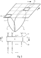
- Fig. 3 (left side) becomes the input vector a 1 of the formula (8) as a vector of the excitation signal proportionately to the feed vectors q i divided.
- the reception case is based on the vectors on the right-hand side (connected by the schematic arrow pointing down) Fig. 3 explained, the input vector a 2 is broken down into its proportions of the individual directional characteristics 7 according to equation (9).
- the vector lies on the upper level of the feed network 9 a 2 before.
- the received signal divided according to the individual directional characteristics a 2 describes the direction of incidence of the signal received in each case.
- transponder generally the transmitter
- transponder assigns to the currently selected (or switched) directional characteristic.
- This process is carried out for several directional characteristics 7. So there are the signal components in the individual C. k read out in succession and the transponder signals or the amplitude amounts can be assigned to the directional characteristics. Overall, a vector is constructed for the position of the transmitter. The values of the entries result from the amounts of the field strengths of the respectively received signals and the base vectors result from the assigned directional characteristics, e.g. B. the respective direction of the club.
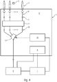
- the Fig. 4 shows an alternative embodiment of the device 1.
- the antenna device 3 is also designed as a multi-lobe antenna and has the control logic 10 and the data processing device 6 (alternatively also referred to as a computing unit).
- the possible complex vectors for different angles of incidence must first be determined.
- the directional characteristic and its spatial distribution of the reception sensitivity (or, as a rule, therefore also its transmission sensitivity) must be determined. This can be done by simulating or measuring the array, in which the vectors for all angles of incidence are recorded over the illumination range ⁇ - as defined in (1). The illumination area is traversed discretely, so that finally a countable (finite) set of known angles of incidence ⁇ l and thus vectors b ⁇ 1 s ⁇ ⁇ l respectively. a ⁇ 2nd s ⁇ ⁇ l results.
- the superscript of (s) indicates that these are the vectors determined for discrete angles of incidence. In principle, these are steering vectors.
- the angle of incidence ⁇ ⁇ ⁇ ⁇ l ⁇ results directly from the complex vector b ⁇ 1 ′ s respectively. a ⁇ 2nd ′ s or from any directional estimation algorithm applied to the vector. It is also possible to determine a time average over several successive angles of incidence, which are determined over several switching cycles. This reduces the variance of the estimated angle and thus the measurement uncertainty.
- existing secondary maxima of the directional characteristics are generally limited to a certain maximum level in relation to the level of the main maximum in order to be robust against possible uncertainties due to superimposed noise to be. Otherwise ambiguities may arise when determining the direction.
- one embodiment provides for the use of a multi-lobe antenna whose directional characteristics have a clear global maximum and no cross-sector symmetries in the form of a further global maximum within the illumination range.
- the combination of a typical or customary RFID reader with a corresponding multi-lobe antenna enables the complex-value received signal to be inferred without having to intervene in the reader.
- the illustration Fig. 4 shows an exemplary architecture of the corresponding structure of the device 1, with the available directional characteristics C. k can be read out in accordance with the procedure described above and the angle of incidence of the identified tags (or transmitter) 2 can be determined.
- the multi-lobe antenna 3 comprises a high-frequency switch (HF switch) 12 and a control logic 10. With the aid of the control logic 10, the desired gate directional characteristic is established via the HF switch 12 C. k (see definition (5)).
- the RF signal to be transmitted is sent as an excitation signal from the external RFID reader 5 (which is thus the signal source 11 of the embodiment of FIG Fig. 1 includes) and the reception signal is provided for the RFID reader 5.
- a control device 4 which is external to the antenna device 3, permits control of the reading device 5 and the multi-lobe antenna 3.
- the data processing device 6 as part of the antenna device 3 determines the direction of incidence of the transponder signals in accordance with equation (13).
- the RSSI values and the transponder identification are obtained from the RFID reader 5.
- the embodiment shown has the advantage that only the antenna provided by the antenna device 3 with control logic 10 and data processing device 6 is closed is replace - additional components are not necessary.
- the invention makes it possible to determine information about a position of the transmitter, which is at least a statement about a direction of the transmitter. This is done based on RSSI values (or generally only with Amplitude values of the received signals) in combination with a multi-lobe antenna.
- a single RF path between the multi-lobe antenna and RFID reader is sufficient for the directional estimation.
- the number of antenna elements or directional characteristics and the division of the illumination area can be chosen as desired. As the number of elements and sectors increases, the accuracy of the direction estimate can be increased. This can therefore be adapted to the respective application.
- a (commercially) standard RFID reader can be used as the signal processing device. These provide an RSSI value for each identified transponder.
- the invention it is possible to dispense with the measurement of complex signals using an antenna device with different switchable or selectable directional characteristics (that is, in a configuration of the multi-lobe antenna) and a corresponding partitioning of the illumination area. Part of the signal processing is carried out, as it were, by the antenna device and its directional characteristics, so that the RSSI values (or generally the amplitude values) are sufficient for the position determination or at least for the direction estimate.
- Technical fields of application of the invention are, for example, logistics, production, gate passages and the like. a. with bulk reading (detection of many transponders in a short time), automated inventory or personal checks (e.g. healthcare).
- aspects have been described in connection with a device, it goes without saying that these aspects also represent a description of the corresponding method, so that a block or a component of a device is also to be understood as a corresponding method step or as a feature of a method step. Analogously, aspects that have been described in connection with or as a method step also represent a description of a corresponding block or detail or feature of a corresponding device.
- Some or all of the method steps can be carried out by a hardware apparatus (or using a hardware device). Apparatus), such as a microprocessor, a programmable computer or an electronic circuit. In some embodiments, some or more of the most important process steps can be performed by such an apparatus.
- exemplary embodiments of the invention can be implemented in hardware or in software or at least partially in hardware or at least partially in software.
- the implementation can be carried out using a digital storage medium, for example a floppy disk, a DVD, a BluRay disc, a CD, a ROM, a PROM, an EPROM, an EEPROM or a FLASH memory, a hard disk or another magnetic or optical memory, on which electronically readable control signals are stored, which are stored with a programmable computer system can cooperate or cooperate that the respective method is carried out.
- the digital storage medium can therefore be computer-readable.
- Some exemplary embodiments according to the invention thus comprise a data carrier which has electronically readable control signals which are able to interact with a programmable computer system in such a way that one of the methods described herein is carried out.
- exemplary embodiments of the present invention can be implemented as a computer program product with a program code, the program code being effective in performing one of the methods when the computer program product runs on a computer.
- the program code can, for example, also be stored on a machine-readable carrier.
- an exemplary embodiment of the method according to the invention is thus a computer program which has a program code for performing one of the methods described here when the computer program runs on a computer.
- Another exemplary embodiment of the method according to the invention is thus a data carrier (or a digital storage medium or a computer-readable medium) on which the computer program for carrying out one of the methods described herein is recorded.
- the data carrier or the digital storage medium or the computer-readable medium are typically tangible and / or non-volatile.
- a further exemplary embodiment of the method according to the invention is thus a data stream or a sequence of signals which represents the computer program for performing one of the methods described herein.
- the data stream or the sequence of signals can be configured, for example, to be transferred over a data communication connection, for example over the Internet.
- a further exemplary embodiment comprises a processing device, for example a computer or a programmable logic component, which is configured or adapted to carry out one of the methods described herein.
- a processing device for example a computer or a programmable logic component, which is configured or adapted to carry out one of the methods described herein.
- Another embodiment includes a computer on which the computer program for performing one of the methods described herein is installed.
- a further exemplary embodiment according to the invention comprises a device or a system which is designed to transmit a computer program for performing at least one of the methods described herein to a receiver.
- the transmission can take place electronically or optically, for example.
- the receiver can be, for example, a computer, a mobile device, a storage device or a similar device.
- the device or the system can comprise, for example, a file server for transmitting the computer program to the recipient.
- a programmable logic device e.g., a field programmable gate array, an FPGA
- a field programmable gate array may cooperate with a microprocessor to perform one of the methods described herein.
- the methods are performed by any hardware device. This can be a universally usable hardware such as a computer processor (CPU) or hardware specific to the method, such as an ASIC or a microprocessor, e.g. B. in the form of an ARM architecture.
Landscapes
- Engineering & Computer Science (AREA)
- Radar, Positioning & Navigation (AREA)
- Remote Sensing (AREA)
- Physics & Mathematics (AREA)
- General Physics & Mathematics (AREA)
- Computer Networks & Wireless Communication (AREA)
- Signal Processing (AREA)
- Variable-Direction Aerials And Aerial Arrays (AREA)
- Mobile Radio Communication Systems (AREA)
- Position Fixing By Use Of Radio Waves (AREA)
Applications Claiming Priority (3)
| Application Number | Priority Date | Filing Date | Title |
|---|---|---|---|
| DE102016202205 | 2016-02-12 | ||
| DE102016213235.0A DE102016213235A1 (de) | 2016-02-12 | 2016-07-20 | Vorrichtung zur Bestimmung einer Position eines Senders und entsprechendes Verfahren |
| PCT/EP2017/053143 WO2017137624A1 (de) | 2016-02-12 | 2017-02-13 | Vorrichtung zur bestimmung einer position eines senders und entsprechendes verfahren |
Publications (2)
| Publication Number | Publication Date |
|---|---|
| EP3414589A1 EP3414589A1 (de) | 2018-12-19 |
| EP3414589B1 true EP3414589B1 (de) | 2020-04-08 |
Family
ID=59410428
Family Applications (1)
| Application Number | Title | Priority Date | Filing Date |
|---|---|---|---|
| EP17708691.5A Active EP3414589B1 (de) | 2016-02-12 | 2017-02-13 | Vorrichtung zur bestimmung einer position eines senders und entsprechendes verfahren |
Country Status (6)
| Country | Link |
|---|---|
| US (1) | US11693079B2 (https=) |
| EP (1) | EP3414589B1 (https=) |
| JP (1) | JP2019509480A (https=) |
| CN (1) | CN109073728A (https=) |
| DE (1) | DE102016213235A1 (https=) |
| WO (1) | WO2017137624A1 (https=) |
Families Citing this family (4)
| Publication number | Priority date | Publication date | Assignee | Title |
|---|---|---|---|---|
| IT201800006710A1 (it) * | 2018-06-27 | 2019-12-27 | Sistema per localizzare almeno un tag RFID nello spazio, in particolare in un ambiente indoor, e relativo metodo. | |
| CN109886051B (zh) * | 2019-01-08 | 2023-10-20 | 快脉信息科技(上海)有限公司 | 一种车辆定位射频识别系统及其快速巡检定位方法 |
| DE102020124638A1 (de) * | 2020-09-22 | 2022-03-24 | Diehl Metering Systems Gmbh | Verfahren zum Betrieb einer Sektor-Antennen-Anordnung sowie Sektor-Antennen-Anordnung |
| JP7741519B2 (ja) * | 2022-08-17 | 2025-09-18 | Ntt株式会社 | 到来方向推定装置及び到来方向推定方法 |
Family Cites Families (21)
| Publication number | Priority date | Publication date | Assignee | Title |
|---|---|---|---|---|
| US4654667A (en) * | 1984-12-21 | 1987-03-31 | Sanders Associates, Inc. | Signal-acquisition system for a circular array |
| US5907809A (en) * | 1994-01-11 | 1999-05-25 | Ericsson Inc. | Position determination using multiple base station signals |
| US6492949B1 (en) * | 2000-08-16 | 2002-12-10 | Raytheon Company | Slot antenna element for an array antenna |
| US7187288B2 (en) * | 2002-03-18 | 2007-03-06 | Paratek Microwave, Inc. | RFID tag reading system and method |
| US20040137909A1 (en) * | 2002-11-25 | 2004-07-15 | Marios Gerogiokas | Capacity adaptive technique for distributed wireless base stations |
| JP2004333414A (ja) * | 2003-05-12 | 2004-11-25 | Hitachi Kokusai Electric Inc | 位置情報検出システム |
| JP4232640B2 (ja) * | 2004-01-21 | 2009-03-04 | トヨタ自動車株式会社 | 方向探知機 |
| JP2006050477A (ja) * | 2004-08-09 | 2006-02-16 | Brother Ind Ltd | 無線タグ通信装置 |
| JP4706914B2 (ja) * | 2005-08-31 | 2011-06-22 | ブラザー工業株式会社 | 物品管理システム |
| US7667646B2 (en) | 2006-02-21 | 2010-02-23 | Nokia Corporation | System and methods for direction finding using a handheld device |
| US20090002165A1 (en) * | 2007-06-28 | 2009-01-01 | Micron Technology, Inc. | Method and system of determining a location characteristic of a rfid tag |
| JP4835670B2 (ja) * | 2008-09-22 | 2011-12-14 | 株式会社デンソー | アンテナ装置 |
| US8461965B2 (en) * | 2010-01-13 | 2013-06-11 | The Boeing Company | Portable radio frequency identification (RFID) reader |
| US8325019B2 (en) * | 2010-09-13 | 2012-12-04 | Ricoh Company, Ltd. | Motion tracking techniques for RFID tags |
| US8433337B2 (en) | 2011-07-18 | 2013-04-30 | Ting-Yueh Chin | RSS-based DOA indoor location estimation system and method |
| WO2014160322A1 (en) * | 2013-03-14 | 2014-10-02 | Impinj, Inc. | Powering rfid tags using multiple systhesized-beam rfid readers |
| US9349032B1 (en) * | 2014-05-22 | 2016-05-24 | Impinj, Inc | RFID loss-prevention using angle-of-arrival |
| US9183717B1 (en) * | 2014-05-22 | 2015-11-10 | Impinj, Inc. | RFID loss-prevention using synthesized-beam readers |
| US20160057206A1 (en) | 2014-08-19 | 2016-02-25 | International Business Machines Corporation | Application profile to configure and manage a software defined environment |
| US9797979B2 (en) * | 2014-10-08 | 2017-10-24 | Symbol Technologies, Llc | System for and method of estimating bearings of radio frequency identification (RFID) tags that return RFID receive signals whose power is below a predetermined threshold |
| CN105305018A (zh) * | 2015-09-29 | 2016-02-03 | 天津工业大学 | Rfid阅读器波束切换型阵列天线 |
-
2016
- 2016-07-20 DE DE102016213235.0A patent/DE102016213235A1/de not_active Withdrawn
-
2017
- 2017-02-13 EP EP17708691.5A patent/EP3414589B1/de active Active
- 2017-02-13 WO PCT/EP2017/053143 patent/WO2017137624A1/de not_active Ceased
- 2017-02-13 CN CN201780023150.6A patent/CN109073728A/zh active Pending
- 2017-02-13 JP JP2018541697A patent/JP2019509480A/ja active Pending
-
2018
- 2018-08-09 US US16/059,794 patent/US11693079B2/en active Active
Non-Patent Citations (1)
| Title |
|---|
| None * |
Also Published As
| Publication number | Publication date |
|---|---|
| JP2019509480A (ja) | 2019-04-04 |
| US20180348327A1 (en) | 2018-12-06 |
| WO2017137624A1 (de) | 2017-08-17 |
| DE102016213235A1 (de) | 2017-08-17 |
| CN109073728A (zh) | 2018-12-21 |
| US11693079B2 (en) | 2023-07-04 |
| EP3414589A1 (de) | 2018-12-19 |
Similar Documents
| Publication | Publication Date | Title |
|---|---|---|
| EP3414589B1 (de) | Vorrichtung zur bestimmung einer position eines senders und entsprechendes verfahren | |
| DE102019125973A1 (de) | Radar-Vorrichtung | |
| DE112014005619T5 (de) | System und Verfahren zum genauen Bestimmen der wahren Stellungen von Hochfrequenz-Identifikations- (Radio Frequency Identification - RFID-) Etiketten, die mit Artileln in einem kontrolierten Bereich verknüpft sind | |
| DE112016004779B4 (de) | Radiofrequenz (RF) -identifikation (RFID) -Etikett-Lesesystem und -Leseverfahren zum genauen und schnellen Bestimmen in Echtzeit von wahren Lagen von RFID-Etiketten, die mit Gegenständen in einem überwachten Bereich assoziiert sind | |
| DE102017210137A1 (de) | Radarvorrichtung und Verfahren zum Verarbeiten eines Radarsignals | |
| DE112020001356T5 (de) | Radar-Vorrichtigung und Sende-/Empfangsgruppenantenne | |
| EP2927838B1 (de) | Vorrichtung und Verfahren zum Identifizieren und Lokalisieren von Objekten | |
| EP3414591B1 (de) | Vorrichtung zur darstellung von benutzerinformationen und entsprechendes verfahren | |
| DE102013204639A1 (de) | Radareinrichtung und Zieldetektierverfahren | |
| WO2010091746A1 (de) | Verfahren und system zur bestimmung der entfernung, der geschwindigkeit und/oder der bewegungsrichtung eines rfid-transponders | |
| EP3414588B1 (de) | Vorrichtung und verfahren zur positionsbestimmung eines senders relativ zu einem detektionsbereich | |
| DE112020002389T5 (de) | Radarvorrichtung, fahrzeug und verfahren zum entfernen eines unnötigen punkts | |
| EP3414587B1 (de) | Vorrichtung zur bestimmung einer position eines senders | |
| DE102020131416A1 (de) | Dynamische kompensation eines phasengesteuerten rfid-lesegeräts | |
| DE112018003823B4 (de) | Verfahren und vorrichtung zur schätzung einer etikett-lage mittels radiofrequenzidentifizierung (rfid) | |
| DE102016204997A1 (de) | Vorrichtung, Verfahren und Computerprogramm zum Lokalisieren von mobilen Geräten | |
| EP3414590B1 (de) | Vorrichtung und verfahren zur bestimmung einer position eines senders | |
| EP3427191B1 (de) | Transponder, insbesondere rfid transponder, und verfahren zum betreiben eines, insbesondere rfid, transponders | |
| DE102005037583A1 (de) | Mikrowellen-RFID-System mit adaptiver Strahlformung | |
| EP1676145A1 (de) | Verfahren und vorrichtung zur funkpeilung mehrerer spektral überlappender funkstationen | |
| EP3362815A1 (de) | Bildgebende polarimetrie | |
| EP2955538A1 (de) | Verfahren und Vorrichtung zur schmalbandigen Entfernungsmessung | |
| DE102023120865B4 (de) | Positionssensor zum ortsaufgelösten Erfassen von Objekten in einem Überwachungsbereich | |
| DE102016213330A1 (de) | Verfahren zur Ortung eines beweglichen Objektes sowie Transponder hierzu | |
| WO2017137626A1 (de) | Vorrichtung zur darstellung von benutzerinformationen und entsprechendes verfahren |
Legal Events
| Date | Code | Title | Description |
|---|---|---|---|
| STAA | Information on the status of an ep patent application or granted ep patent |
Free format text: STATUS: UNKNOWN |
|
| STAA | Information on the status of an ep patent application or granted ep patent |
Free format text: STATUS: THE INTERNATIONAL PUBLICATION HAS BEEN MADE |
|
| PUAI | Public reference made under article 153(3) epc to a published international application that has entered the european phase |
Free format text: ORIGINAL CODE: 0009012 |
|
| STAA | Information on the status of an ep patent application or granted ep patent |
Free format text: STATUS: REQUEST FOR EXAMINATION WAS MADE |
|
| 17P | Request for examination filed |
Effective date: 20180803 |
|
| AK | Designated contracting states |
Kind code of ref document: A1 Designated state(s): AL AT BE BG CH CY CZ DE DK EE ES FI FR GB GR HR HU IE IS IT LI LT LU LV MC MK MT NL NO PL PT RO RS SE SI SK SM TR |
|
| AX | Request for extension of the european patent |
Extension state: BA ME |
|
| DAV | Request for validation of the european patent (deleted) | ||
| DAX | Request for extension of the european patent (deleted) | ||
| GRAP | Despatch of communication of intention to grant a patent |
Free format text: ORIGINAL CODE: EPIDOSNIGR1 |
|
| STAA | Information on the status of an ep patent application or granted ep patent |
Free format text: STATUS: GRANT OF PATENT IS INTENDED |
|
| INTG | Intention to grant announced |
Effective date: 20191021 |
|
| GRAS | Grant fee paid |
Free format text: ORIGINAL CODE: EPIDOSNIGR3 |
|
| GRAA | (expected) grant |
Free format text: ORIGINAL CODE: 0009210 |
|
| STAA | Information on the status of an ep patent application or granted ep patent |
Free format text: STATUS: THE PATENT HAS BEEN GRANTED |
|
| AK | Designated contracting states |
Kind code of ref document: B1 Designated state(s): AL AT BE BG CH CY CZ DE DK EE ES FI FR GB GR HR HU IE IS IT LI LT LU LV MC MK MT NL NO PL PT RO RS SE SI SK SM TR |
|
| REG | Reference to a national code |
Ref country code: AT Ref legal event code: REF Ref document number: 1255132 Country of ref document: AT Kind code of ref document: T Effective date: 20200415 Ref country code: CH Ref legal event code: EP |
|
| REG | Reference to a national code |
Ref country code: DE Ref legal event code: R096 Ref document number: 502017004658 Country of ref document: DE |
|
| REG | Reference to a national code |
Ref country code: IE Ref legal event code: FG4D Free format text: LANGUAGE OF EP DOCUMENT: GERMAN |
|
| REG | Reference to a national code |
Ref country code: NL Ref legal event code: MP Effective date: 20200408 |
|
| REG | Reference to a national code |
Ref country code: LT Ref legal event code: MG4D |
|
| PG25 | Lapsed in a contracting state [announced via postgrant information from national office to epo] |
Ref country code: FI Free format text: LAPSE BECAUSE OF FAILURE TO SUBMIT A TRANSLATION OF THE DESCRIPTION OR TO PAY THE FEE WITHIN THE PRESCRIBED TIME-LIMIT Effective date: 20200408 Ref country code: IS Free format text: LAPSE BECAUSE OF FAILURE TO SUBMIT A TRANSLATION OF THE DESCRIPTION OR TO PAY THE FEE WITHIN THE PRESCRIBED TIME-LIMIT Effective date: 20200808 Ref country code: SE Free format text: LAPSE BECAUSE OF FAILURE TO SUBMIT A TRANSLATION OF THE DESCRIPTION OR TO PAY THE FEE WITHIN THE PRESCRIBED TIME-LIMIT Effective date: 20200408 Ref country code: LT Free format text: LAPSE BECAUSE OF FAILURE TO SUBMIT A TRANSLATION OF THE DESCRIPTION OR TO PAY THE FEE WITHIN THE PRESCRIBED TIME-LIMIT Effective date: 20200408 Ref country code: PT Free format text: LAPSE BECAUSE OF FAILURE TO SUBMIT A TRANSLATION OF THE DESCRIPTION OR TO PAY THE FEE WITHIN THE PRESCRIBED TIME-LIMIT Effective date: 20200817 Ref country code: NL Free format text: LAPSE BECAUSE OF FAILURE TO SUBMIT A TRANSLATION OF THE DESCRIPTION OR TO PAY THE FEE WITHIN THE PRESCRIBED TIME-LIMIT Effective date: 20200408 Ref country code: NO Free format text: LAPSE BECAUSE OF FAILURE TO SUBMIT A TRANSLATION OF THE DESCRIPTION OR TO PAY THE FEE WITHIN THE PRESCRIBED TIME-LIMIT Effective date: 20200708 Ref country code: GR Free format text: LAPSE BECAUSE OF FAILURE TO SUBMIT A TRANSLATION OF THE DESCRIPTION OR TO PAY THE FEE WITHIN THE PRESCRIBED TIME-LIMIT Effective date: 20200709 |
|
| PG25 | Lapsed in a contracting state [announced via postgrant information from national office to epo] |
Ref country code: RS Free format text: LAPSE BECAUSE OF FAILURE TO SUBMIT A TRANSLATION OF THE DESCRIPTION OR TO PAY THE FEE WITHIN THE PRESCRIBED TIME-LIMIT Effective date: 20200408 Ref country code: BG Free format text: LAPSE BECAUSE OF FAILURE TO SUBMIT A TRANSLATION OF THE DESCRIPTION OR TO PAY THE FEE WITHIN THE PRESCRIBED TIME-LIMIT Effective date: 20200708 Ref country code: LV Free format text: LAPSE BECAUSE OF FAILURE TO SUBMIT A TRANSLATION OF THE DESCRIPTION OR TO PAY THE FEE WITHIN THE PRESCRIBED TIME-LIMIT Effective date: 20200408 Ref country code: HR Free format text: LAPSE BECAUSE OF FAILURE TO SUBMIT A TRANSLATION OF THE DESCRIPTION OR TO PAY THE FEE WITHIN THE PRESCRIBED TIME-LIMIT Effective date: 20200408 |
|
| PG25 | Lapsed in a contracting state [announced via postgrant information from national office to epo] |
Ref country code: AL Free format text: LAPSE BECAUSE OF FAILURE TO SUBMIT A TRANSLATION OF THE DESCRIPTION OR TO PAY THE FEE WITHIN THE PRESCRIBED TIME-LIMIT Effective date: 20200408 |
|
| REG | Reference to a national code |
Ref country code: DE Ref legal event code: R097 Ref document number: 502017004658 Country of ref document: DE |
|
| PG25 | Lapsed in a contracting state [announced via postgrant information from national office to epo] |
Ref country code: DK Free format text: LAPSE BECAUSE OF FAILURE TO SUBMIT A TRANSLATION OF THE DESCRIPTION OR TO PAY THE FEE WITHIN THE PRESCRIBED TIME-LIMIT Effective date: 20200408 Ref country code: IT Free format text: LAPSE BECAUSE OF FAILURE TO SUBMIT A TRANSLATION OF THE DESCRIPTION OR TO PAY THE FEE WITHIN THE PRESCRIBED TIME-LIMIT Effective date: 20200408 Ref country code: EE Free format text: LAPSE BECAUSE OF FAILURE TO SUBMIT A TRANSLATION OF THE DESCRIPTION OR TO PAY THE FEE WITHIN THE PRESCRIBED TIME-LIMIT Effective date: 20200408 Ref country code: SM Free format text: LAPSE BECAUSE OF FAILURE TO SUBMIT A TRANSLATION OF THE DESCRIPTION OR TO PAY THE FEE WITHIN THE PRESCRIBED TIME-LIMIT Effective date: 20200408 Ref country code: ES Free format text: LAPSE BECAUSE OF FAILURE TO SUBMIT A TRANSLATION OF THE DESCRIPTION OR TO PAY THE FEE WITHIN THE PRESCRIBED TIME-LIMIT Effective date: 20200408 Ref country code: RO Free format text: LAPSE BECAUSE OF FAILURE TO SUBMIT A TRANSLATION OF THE DESCRIPTION OR TO PAY THE FEE WITHIN THE PRESCRIBED TIME-LIMIT Effective date: 20200408 Ref country code: CZ Free format text: LAPSE BECAUSE OF FAILURE TO SUBMIT A TRANSLATION OF THE DESCRIPTION OR TO PAY THE FEE WITHIN THE PRESCRIBED TIME-LIMIT Effective date: 20200408 |
|
| PLBE | No opposition filed within time limit |
Free format text: ORIGINAL CODE: 0009261 |
|
| STAA | Information on the status of an ep patent application or granted ep patent |
Free format text: STATUS: NO OPPOSITION FILED WITHIN TIME LIMIT |
|
| PG25 | Lapsed in a contracting state [announced via postgrant information from national office to epo] |
Ref country code: SK Free format text: LAPSE BECAUSE OF FAILURE TO SUBMIT A TRANSLATION OF THE DESCRIPTION OR TO PAY THE FEE WITHIN THE PRESCRIBED TIME-LIMIT Effective date: 20200408 Ref country code: PL Free format text: LAPSE BECAUSE OF FAILURE TO SUBMIT A TRANSLATION OF THE DESCRIPTION OR TO PAY THE FEE WITHIN THE PRESCRIBED TIME-LIMIT Effective date: 20200408 |
|
| 26N | No opposition filed |
Effective date: 20210112 |
|
| PG25 | Lapsed in a contracting state [announced via postgrant information from national office to epo] |
Ref country code: SI Free format text: LAPSE BECAUSE OF FAILURE TO SUBMIT A TRANSLATION OF THE DESCRIPTION OR TO PAY THE FEE WITHIN THE PRESCRIBED TIME-LIMIT Effective date: 20200408 |
|
| PG25 | Lapsed in a contracting state [announced via postgrant information from national office to epo] |
Ref country code: MC Free format text: LAPSE BECAUSE OF FAILURE TO SUBMIT A TRANSLATION OF THE DESCRIPTION OR TO PAY THE FEE WITHIN THE PRESCRIBED TIME-LIMIT Effective date: 20200408 |
|
| REG | Reference to a national code |
Ref country code: BE Ref legal event code: MM Effective date: 20210228 |
|
| PG25 | Lapsed in a contracting state [announced via postgrant information from national office to epo] |
Ref country code: CH Free format text: LAPSE BECAUSE OF NON-PAYMENT OF DUE FEES Effective date: 20210228 Ref country code: LI Free format text: LAPSE BECAUSE OF NON-PAYMENT OF DUE FEES Effective date: 20210228 Ref country code: LU Free format text: LAPSE BECAUSE OF NON-PAYMENT OF DUE FEES Effective date: 20210213 |
|
| PG25 | Lapsed in a contracting state [announced via postgrant information from national office to epo] |
Ref country code: IE Free format text: LAPSE BECAUSE OF NON-PAYMENT OF DUE FEES Effective date: 20210213 |
|
| PGFP | Annual fee paid to national office [announced via postgrant information from national office to epo] |
Ref country code: TR Payment date: 20220201 Year of fee payment: 6 |
|
| PG25 | Lapsed in a contracting state [announced via postgrant information from national office to epo] |
Ref country code: BE Free format text: LAPSE BECAUSE OF NON-PAYMENT OF DUE FEES Effective date: 20210228 |
|
| REG | Reference to a national code |
Ref country code: AT Ref legal event code: MM01 Ref document number: 1255132 Country of ref document: AT Kind code of ref document: T Effective date: 20220213 |
|
| PG25 | Lapsed in a contracting state [announced via postgrant information from national office to epo] |
Ref country code: AT Free format text: LAPSE BECAUSE OF NON-PAYMENT OF DUE FEES Effective date: 20220213 |
|
| P01 | Opt-out of the competence of the unified patent court (upc) registered |
Effective date: 20230524 |
|
| PG25 | Lapsed in a contracting state [announced via postgrant information from national office to epo] |
Ref country code: CY Free format text: LAPSE BECAUSE OF FAILURE TO SUBMIT A TRANSLATION OF THE DESCRIPTION OR TO PAY THE FEE WITHIN THE PRESCRIBED TIME-LIMIT Effective date: 20200408 |
|
| PG25 | Lapsed in a contracting state [announced via postgrant information from national office to epo] |
Ref country code: HU Free format text: LAPSE BECAUSE OF FAILURE TO SUBMIT A TRANSLATION OF THE DESCRIPTION OR TO PAY THE FEE WITHIN THE PRESCRIBED TIME-LIMIT; INVALID AB INITIO Effective date: 20170213 |
|
| PG25 | Lapsed in a contracting state [announced via postgrant information from national office to epo] |
Ref country code: MK Free format text: LAPSE BECAUSE OF FAILURE TO SUBMIT A TRANSLATION OF THE DESCRIPTION OR TO PAY THE FEE WITHIN THE PRESCRIBED TIME-LIMIT Effective date: 20200408 |
|
| PG25 | Lapsed in a contracting state [announced via postgrant information from national office to epo] |
Ref country code: MT Free format text: LAPSE BECAUSE OF FAILURE TO SUBMIT A TRANSLATION OF THE DESCRIPTION OR TO PAY THE FEE WITHIN THE PRESCRIBED TIME-LIMIT Effective date: 20200408 |
|
| PGFP | Annual fee paid to national office [announced via postgrant information from national office to epo] |
Ref country code: GB Payment date: 20260219 Year of fee payment: 10 |
|
| PGFP | Annual fee paid to national office [announced via postgrant information from national office to epo] |
Ref country code: DE Payment date: 20260217 Year of fee payment: 10 |
|
| PGFP | Annual fee paid to national office [announced via postgrant information from national office to epo] |
Ref country code: FR Payment date: 20260223 Year of fee payment: 10 |