EP3412966B1 - Projector - Google Patents
Projector Download PDFInfo
- Publication number
- EP3412966B1 EP3412966B1 EP17747409.5A EP17747409A EP3412966B1 EP 3412966 B1 EP3412966 B1 EP 3412966B1 EP 17747409 A EP17747409 A EP 17747409A EP 3412966 B1 EP3412966 B1 EP 3412966B1
- Authority
- EP
- European Patent Office
- Prior art keywords
- floodlight
- heatsink
- led
- shaped
- air
- Prior art date
- Legal status (The legal status is an assumption and is not a legal conclusion. Google has not performed a legal analysis and makes no representation as to the accuracy of the status listed.)
- Active
Links
- 238000001816 cooling Methods 0.000 claims description 33
- 230000017525 heat dissipation Effects 0.000 claims description 16
- XLYOFNOQVPJJNP-UHFFFAOYSA-N water Substances O XLYOFNOQVPJJNP-UHFFFAOYSA-N 0.000 claims description 9
- 230000008878 coupling Effects 0.000 claims description 4
- 238000010168 coupling process Methods 0.000 claims description 4
- 238000005859 coupling reaction Methods 0.000 claims description 4
- 239000003570 air Substances 0.000 description 24
- 230000000694 effects Effects 0.000 description 6
- 239000000463 material Substances 0.000 description 4
- 125000006850 spacer group Chemical group 0.000 description 4
- 238000010276 construction Methods 0.000 description 2
- 230000020169 heat generation Effects 0.000 description 2
- 238000000034 method Methods 0.000 description 2
- 239000000758 substrate Substances 0.000 description 2
- 229920000544 Gore-Tex Polymers 0.000 description 1
- 229910000861 Mg alloy Inorganic materials 0.000 description 1
- XAGFODPZIPBFFR-UHFFFAOYSA-N aluminium Chemical compound [Al] XAGFODPZIPBFFR-UHFFFAOYSA-N 0.000 description 1
- 229910052782 aluminium Inorganic materials 0.000 description 1
- 239000012080 ambient air Substances 0.000 description 1
- 230000001174 ascending effect Effects 0.000 description 1
- 230000009286 beneficial effect Effects 0.000 description 1
- 238000007796 conventional method Methods 0.000 description 1
- -1 e.g. Substances 0.000 description 1
- 238000004519 manufacturing process Methods 0.000 description 1
- 229920000515 polycarbonate Polymers 0.000 description 1
- 239000004417 polycarbonate Substances 0.000 description 1
- 239000011347 resin Substances 0.000 description 1
- 229920005989 resin Polymers 0.000 description 1
- 239000012815 thermoplastic material Substances 0.000 description 1
Images


Classifications
-
- F—MECHANICAL ENGINEERING; LIGHTING; HEATING; WEAPONS; BLASTING
- F21—LIGHTING
- F21V—FUNCTIONAL FEATURES OR DETAILS OF LIGHTING DEVICES OR SYSTEMS THEREOF; STRUCTURAL COMBINATIONS OF LIGHTING DEVICES WITH OTHER ARTICLES, NOT OTHERWISE PROVIDED FOR
- F21V29/00—Protecting lighting devices from thermal damage; Cooling or heating arrangements specially adapted for lighting devices or systems
- F21V29/50—Cooling arrangements
- F21V29/60—Cooling arrangements characterised by the use of a forced flow of gas, e.g. air
- F21V29/67—Cooling arrangements characterised by the use of a forced flow of gas, e.g. air characterised by the arrangement of fans
- F21V29/677—Cooling arrangements characterised by the use of a forced flow of gas, e.g. air characterised by the arrangement of fans the fans being used for discharging
-
- F—MECHANICAL ENGINEERING; LIGHTING; HEATING; WEAPONS; BLASTING
- F21—LIGHTING
- F21V—FUNCTIONAL FEATURES OR DETAILS OF LIGHTING DEVICES OR SYSTEMS THEREOF; STRUCTURAL COMBINATIONS OF LIGHTING DEVICES WITH OTHER ARTICLES, NOT OTHERWISE PROVIDED FOR
- F21V29/00—Protecting lighting devices from thermal damage; Cooling or heating arrangements specially adapted for lighting devices or systems
- F21V29/50—Cooling arrangements
- F21V29/502—Cooling arrangements characterised by the adaptation for cooling of specific components
- F21V29/503—Cooling arrangements characterised by the adaptation for cooling of specific components of light sources
-
- F—MECHANICAL ENGINEERING; LIGHTING; HEATING; WEAPONS; BLASTING
- F21—LIGHTING
- F21S—NON-PORTABLE LIGHTING DEVICES; SYSTEMS THEREOF; VEHICLE LIGHTING DEVICES SPECIALLY ADAPTED FOR VEHICLE EXTERIORS
- F21S2/00—Systems of lighting devices, not provided for in main groups F21S4/00 - F21S10/00 or F21S19/00, e.g. of modular construction
-
- F—MECHANICAL ENGINEERING; LIGHTING; HEATING; WEAPONS; BLASTING
- F21—LIGHTING
- F21S—NON-PORTABLE LIGHTING DEVICES; SYSTEMS THEREOF; VEHICLE LIGHTING DEVICES SPECIALLY ADAPTED FOR VEHICLE EXTERIORS
- F21S6/00—Lighting devices intended to be free-standing
- F21S6/005—Lighting devices intended to be free-standing with a lamp housing maintained at a distance from the floor or ground via a support, e.g. standing lamp for ambient lighting
- F21S6/006—Lighting devices intended to be free-standing with a lamp housing maintained at a distance from the floor or ground via a support, e.g. standing lamp for ambient lighting for direct lighting only, e.g. task lighting
-
- F—MECHANICAL ENGINEERING; LIGHTING; HEATING; WEAPONS; BLASTING
- F21—LIGHTING
- F21V—FUNCTIONAL FEATURES OR DETAILS OF LIGHTING DEVICES OR SYSTEMS THEREOF; STRUCTURAL COMBINATIONS OF LIGHTING DEVICES WITH OTHER ARTICLES, NOT OTHERWISE PROVIDED FOR
- F21V29/00—Protecting lighting devices from thermal damage; Cooling or heating arrangements specially adapted for lighting devices or systems
- F21V29/50—Cooling arrangements
- F21V29/60—Cooling arrangements characterised by the use of a forced flow of gas, e.g. air
- F21V29/67—Cooling arrangements characterised by the use of a forced flow of gas, e.g. air characterised by the arrangement of fans
-
- F—MECHANICAL ENGINEERING; LIGHTING; HEATING; WEAPONS; BLASTING
- F21—LIGHTING
- F21V—FUNCTIONAL FEATURES OR DETAILS OF LIGHTING DEVICES OR SYSTEMS THEREOF; STRUCTURAL COMBINATIONS OF LIGHTING DEVICES WITH OTHER ARTICLES, NOT OTHERWISE PROVIDED FOR
- F21V29/00—Protecting lighting devices from thermal damage; Cooling or heating arrangements specially adapted for lighting devices or systems
- F21V29/50—Cooling arrangements
- F21V29/70—Cooling arrangements characterised by passive heat-dissipating elements, e.g. heat-sinks
- F21V29/74—Cooling arrangements characterised by passive heat-dissipating elements, e.g. heat-sinks with fins or blades
- F21V29/77—Cooling arrangements characterised by passive heat-dissipating elements, e.g. heat-sinks with fins or blades with essentially identical diverging planar fins or blades, e.g. with fan-like or star-like cross-section
- F21V29/773—Cooling arrangements characterised by passive heat-dissipating elements, e.g. heat-sinks with fins or blades with essentially identical diverging planar fins or blades, e.g. with fan-like or star-like cross-section the planes containing the fins or blades having the direction of the light emitting axis
-
- F—MECHANICAL ENGINEERING; LIGHTING; HEATING; WEAPONS; BLASTING
- F21—LIGHTING
- F21V—FUNCTIONAL FEATURES OR DETAILS OF LIGHTING DEVICES OR SYSTEMS THEREOF; STRUCTURAL COMBINATIONS OF LIGHTING DEVICES WITH OTHER ARTICLES, NOT OTHERWISE PROVIDED FOR
- F21V29/00—Protecting lighting devices from thermal damage; Cooling or heating arrangements specially adapted for lighting devices or systems
- F21V29/50—Cooling arrangements
- F21V29/70—Cooling arrangements characterised by passive heat-dissipating elements, e.g. heat-sinks
- F21V29/74—Cooling arrangements characterised by passive heat-dissipating elements, e.g. heat-sinks with fins or blades
- F21V29/77—Cooling arrangements characterised by passive heat-dissipating elements, e.g. heat-sinks with fins or blades with essentially identical diverging planar fins or blades, e.g. with fan-like or star-like cross-section
- F21V29/777—Cooling arrangements characterised by passive heat-dissipating elements, e.g. heat-sinks with fins or blades with essentially identical diverging planar fins or blades, e.g. with fan-like or star-like cross-section the planes containing the fins or blades having directions perpendicular to the light emitting axis
-
- F—MECHANICAL ENGINEERING; LIGHTING; HEATING; WEAPONS; BLASTING
- F21—LIGHTING
- F21V—FUNCTIONAL FEATURES OR DETAILS OF LIGHTING DEVICES OR SYSTEMS THEREOF; STRUCTURAL COMBINATIONS OF LIGHTING DEVICES WITH OTHER ARTICLES, NOT OTHERWISE PROVIDED FOR
- F21V29/00—Protecting lighting devices from thermal damage; Cooling or heating arrangements specially adapted for lighting devices or systems
- F21V29/50—Cooling arrangements
- F21V29/70—Cooling arrangements characterised by passive heat-dissipating elements, e.g. heat-sinks
- F21V29/83—Cooling arrangements characterised by passive heat-dissipating elements, e.g. heat-sinks the elements having apertures, ducts or channels, e.g. heat radiation holes
-
- F—MECHANICAL ENGINEERING; LIGHTING; HEATING; WEAPONS; BLASTING
- F21—LIGHTING
- F21S—NON-PORTABLE LIGHTING DEVICES; SYSTEMS THEREOF; VEHICLE LIGHTING DEVICES SPECIALLY ADAPTED FOR VEHICLE EXTERIORS
- F21S8/00—Lighting devices intended for fixed installation
- F21S8/08—Lighting devices intended for fixed installation with a standard
- F21S8/085—Lighting devices intended for fixed installation with a standard of high-built type, e.g. street light
-
- F—MECHANICAL ENGINEERING; LIGHTING; HEATING; WEAPONS; BLASTING
- F21—LIGHTING
- F21V—FUNCTIONAL FEATURES OR DETAILS OF LIGHTING DEVICES OR SYSTEMS THEREOF; STRUCTURAL COMBINATIONS OF LIGHTING DEVICES WITH OTHER ARTICLES, NOT OTHERWISE PROVIDED FOR
- F21V23/00—Arrangement of electric circuit elements in or on lighting devices
- F21V23/02—Arrangement of electric circuit elements in or on lighting devices the elements being transformers, impedances or power supply units, e.g. a transformer with a rectifier
-
- F—MECHANICAL ENGINEERING; LIGHTING; HEATING; WEAPONS; BLASTING
- F21—LIGHTING
- F21V—FUNCTIONAL FEATURES OR DETAILS OF LIGHTING DEVICES OR SYSTEMS THEREOF; STRUCTURAL COMBINATIONS OF LIGHTING DEVICES WITH OTHER ARTICLES, NOT OTHERWISE PROVIDED FOR
- F21V29/00—Protecting lighting devices from thermal damage; Cooling or heating arrangements specially adapted for lighting devices or systems
- F21V29/50—Cooling arrangements
- F21V29/502—Cooling arrangements characterised by the adaptation for cooling of specific components
- F21V29/508—Cooling arrangements characterised by the adaptation for cooling of specific components of electrical circuits
-
- F—MECHANICAL ENGINEERING; LIGHTING; HEATING; WEAPONS; BLASTING
- F21—LIGHTING
- F21V—FUNCTIONAL FEATURES OR DETAILS OF LIGHTING DEVICES OR SYSTEMS THEREOF; STRUCTURAL COMBINATIONS OF LIGHTING DEVICES WITH OTHER ARTICLES, NOT OTHERWISE PROVIDED FOR
- F21V31/00—Gas-tight or water-tight arrangements
- F21V31/005—Sealing arrangements therefor
-
- F—MECHANICAL ENGINEERING; LIGHTING; HEATING; WEAPONS; BLASTING
- F21—LIGHTING
- F21W—INDEXING SCHEME ASSOCIATED WITH SUBCLASSES F21K, F21L, F21S and F21V, RELATING TO USES OR APPLICATIONS OF LIGHTING DEVICES OR SYSTEMS
- F21W2131/00—Use or application of lighting devices or systems not provided for in codes F21W2102/00-F21W2121/00
- F21W2131/10—Outdoor lighting
- F21W2131/1005—Outdoor lighting of working places, building sites or the like
-
- F—MECHANICAL ENGINEERING; LIGHTING; HEATING; WEAPONS; BLASTING
- F21—LIGHTING
- F21W—INDEXING SCHEME ASSOCIATED WITH SUBCLASSES F21K, F21L, F21S and F21V, RELATING TO USES OR APPLICATIONS OF LIGHTING DEVICES OR SYSTEMS
- F21W2131/00—Use or application of lighting devices or systems not provided for in codes F21W2102/00-F21W2121/00
- F21W2131/10—Outdoor lighting
- F21W2131/105—Outdoor lighting of arenas or the like
-
- F—MECHANICAL ENGINEERING; LIGHTING; HEATING; WEAPONS; BLASTING
- F21—LIGHTING
- F21W—INDEXING SCHEME ASSOCIATED WITH SUBCLASSES F21K, F21L, F21S and F21V, RELATING TO USES OR APPLICATIONS OF LIGHTING DEVICES OR SYSTEMS
- F21W2131/00—Use or application of lighting devices or systems not provided for in codes F21W2102/00-F21W2121/00
- F21W2131/40—Lighting for industrial, commercial, recreational or military use
- F21W2131/407—Lighting for industrial, commercial, recreational or military use for indoor arenas
-
- F—MECHANICAL ENGINEERING; LIGHTING; HEATING; WEAPONS; BLASTING
- F21—LIGHTING
- F21Y—INDEXING SCHEME ASSOCIATED WITH SUBCLASSES F21K, F21L, F21S and F21V, RELATING TO THE FORM OR THE KIND OF THE LIGHT SOURCES OR OF THE COLOUR OF THE LIGHT EMITTED
- F21Y2105/00—Planar light sources
- F21Y2105/10—Planar light sources comprising a two-dimensional array of point-like light-generating elements
-
- F—MECHANICAL ENGINEERING; LIGHTING; HEATING; WEAPONS; BLASTING
- F21—LIGHTING
- F21Y—INDEXING SCHEME ASSOCIATED WITH SUBCLASSES F21K, F21L, F21S and F21V, RELATING TO THE FORM OR THE KIND OF THE LIGHT SOURCES OR OF THE COLOUR OF THE LIGHT EMITTED
- F21Y2115/00—Light-generating elements of semiconductor light sources
- F21Y2115/10—Light-emitting diodes [LED]
Definitions
- the present invention pertains to an LED floodlight in which a large number of LEDs is arranged as a light-emitting means and relates to an LED floodlight with a heat dissipation structure that efficiently reduces heat generation of the LEDs and a power supply portion.
- Lighting equipment using an LED including those with a variety of outputs, shapes, and sizes, for example, a light at a construction site, a light at a public facility or sports stadium, and a floodlight for indoor use, in which one or more LEDs are sealed in a mounting case (lighting instrument), has been put into practical use.
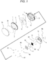
- An LED floodlight 1 or the like is mounted on an LED floodlight device with a high-power battery device 22 as illustrated, for example, in Figs. 5 to 7 and is used by being placed in an appropriate location at a construction site, a public facility, or the like.
- the LED floodlight device usually moves with a telescopic post 23 being contracted.
- the LED floodlight device is often used with the post being extended (see Figs. 5 and 6 ) in use (for example, the telescopic post 23 is extended to a height of about 5 m).
- An LED floodlight 1 is focused on a compact design in terms of both weight and volume.
- examples of a drive power supply for lighting thereof include those housed in a common lighting instrument together with the LED and those configured as a separate component with respect to the lighting instrument body as a separate unit (power supply circuit) with respect to the lighting instrument of the LED.
- an LED requiring a large amount of light is configured to be a floodlight device with a large amount of light as a whole such that LEDs are arranged lengthwise and crosswise.
- An LED floodlight for use in such a floodlight device has a larger number of LEDs mounted on one LED floodlight than LED lighting equipment used indoors or the like. When a large number thereof is arranged as a floodlight device, the resulting amount of heat generation is enormous.
- An LED is current-driven, and the electric power that does not contribute to light emission becomes heat, which remains in the lighting instrument.
- a floodlight device in which a plurality of LED floodlights is arranged, it is difficult to obtain a sufficient heat dissipation effect with a usual heatsink, e.g., a heat dissipation fin, provided one each LED floodlight.
- An LED lighting device disclosed in JP 2016-12516 A is disclosed to be configured to include a panel-shaped floodlight portion in which a front surface is a floodlight portion formed of an LED and a floodlight portion heat dissipation portion that is provided on the back surface of the panel-shaped floodlight portion and dissipates the heat transferred from the LED through stack effect.
- JP 2014-154434 A an LED is arranged at the end of an axial D side of a cylindrical portion of an enclosure on which the LED is mounted, and, in this enclosure, a fan is arranged between an outlet-side punched portion and an inlet-side punched portion. Disclosed is a configuration in which, when the LED is driven, the fan is driven, so that air flowing through the inlet-side punched portion cools the LED and is discharged through the outlet-side punched portion.
- a similar LED lamp is also known from US 2010/0020537 A1 .
- An LED lamp according to the state of the art comprising radially arranged heat dissipation plats on a heatsink with a curved surface portion and a fan is also known from US 2012/0008330 A1 .
- JP 2016-12516 A is provided on the back surface of the panel-shaped floodlight portion and enables efficient dissipation of the heat transferred from the LED through stack effect.
- the technique uses a temperature-induced ascending air that moves upward from below. The effect varies with location where the floodlight is used. In addition, a reduction in size is difficult.
- the heat dissipation structure indicated in JP 2014-154434 A uses a cooling fan.
- the cooling fan is driven, so that the air flowing through the inlet-side punched portion cools the LED and is discharged through the outlet-side punched portion.
- an aluminum substrate on which the LED is mounted is not cooled sufficiently, and the efficiency is not good.
- the application of the conventional heat dissipation structure of LED lighting equipment as it is to a large-sized (a large light amount) floodlight is not realistic in consideration of the manufacturing cost of the equipment and the accessory costs required for placement of a completed floodlight. It is an object of the present invention to provide an LED floodlight that enables efficient use of a cooling means, e.g., a cooling fan, and can pursue a reduction in size.
- a cooling means e.g., a cooling fan
- the LED floodlight according to the present invention is configured in the manner described below.
- reference numerals in the drawings of an example are noted in the description.
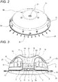
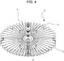
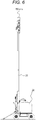
- the LED floodlight 1 of the present invention is configured such that a panel-shaped floodlight portion 2 formed as a floodlight surface is formed such that LEDs L are arranged on a front surface, a heatsink 3 having heat dissipation plates 7 on the back surface of the panel-shaped floodlight portion 2, and furthermore a cooling fan 4 for sending air to a central portion of the heatsink 3 are arranged in this order, and a power supply circuit 5 is provided such that the power supply circuit is placed on the back surface side or outside of the panel-shaped floodlight portion 2.
- the heat dissipation plates 7 of the heatsink 3 are radially arranged from a central portion to the periphery.
- a central portion of a coupling portion 8 between the heat dissipation plates 7 of the heatsink 3 is configured to protrude toward the cooling fan that sends air, and have a curved surface portion 9 from a central portion to the periphery.
- the panel-shaped floodlight portion 2 is closed by being covered with a transparent cover 2a on a front surface side, which is the floodlight surface, and includes an air adjustment tube 10 extending through the heatsink 3 from the floodlight surface.
- the air adjustment tube 10 includes a water shut-off valve that prevents water entry.
- a first cover member 12 is provided, and furthermore the first cover member 12 is configured to include an air intake hole 15 for the cooling fan 4 at a central portion so that the cooling fan 4 is mounted.
- the power supply circuit 5 is mounted on a surface opposite to the panel-shaped floodlight portion of the plate-shaped member 6 and is configured to be a power supply plate. Furthermore, the power supply plate 6 includes an air passage hole 16 for the cooling fan 4 at a central portion, and is interposed and fixed between the heatsink 3 and the first cover member 12.
- the first cover member 12 is provided with a second cover member 13 for covering a central portion of the first cover member 12 at a distance that forms an air intake passage.
- the plurality of heat dissipation plates 7 of the heatsink 3 is radially arranged from a central portion to the periphery, and a central portion of the coupling portion 8 between the heat dissipation plates 7 is configured to protrude toward the cooling fan that sends air and have the curved surface portion 9 from a central portion to the periphery. Therefore, the heatsink can be closely attached to the cooling fan so that the LED floodlight can be configured to be compact as a whole and the cooling effect can be increased, enabling an increase in output of the LED floodlight with ease.
- An LED floodlight 1 includes a panel-shaped floodlight portion 2 formed as a large number of LEDs L is arranged on a substrate to form a floodlight surface, and a heatsink 3 is closely attached to a back surface side of the floodlight surface. As also illustrated in Fig. 3 , the floodlight surface of the LED floodlight 1 is closed with a transparent cover 2a including a fixation groove 17 to which the periphery of a first cover member 12 to be described later is fit and fixedly secured.
- a cover fixation groove 17 of the transparent cover 2a includes, on the inner circumferential side, an O-ring fixation groove 18 for retaining an O-ring 2b made of resin or rubber. Being closed by the transparent cover 2a, the floodlight surface of the panel-shaped floodlight portion 2 forms a closed chamber. It is preferable that thermoplastic material, e.g., polycarbonate, be selected as the material of the transparent cover 2a in consideration of safety and weatherability.
- the panel-shaped floodlight portion 2 includes an air adjustment tube 10 extending through the heatsink 3 from the floodlight surface and a water shut-off valve 11 for preventing water entry. Therefore, the chamber of the panel-shaped floodlight portion 2 on the floodlight surface side is structured to relax a pressure relative to the ambient air and prevent water entry. Regarding the material of the water shut-off valve 11, a valve, for example, of GORE-TEX (registered trademark of W. L. Gore & Associates, Inc.), is desirable.
- GORE-TEX registered trademark of W. L. Gore & Associates, Inc.
- a power supply circuit 5 for supplying electric power to the panel-shaped floodlight portion 2 is mounted on a plate-shaped member and is configured to be a power supply plate 6. Furthermore, the power supply plate 6 includes an air passage hole 16 for a cooling fan 4 at a central portion and is interposed and fixed by screws between the heatsink 3 and the first cover member 12.
- the heatsink 3 is provided with the first cover member 12, and furthermore the first cover member 12 includes an air intake hole 15 for the cooling fan 4 at a central portion so that the cooling fan 4 is mounted.
- the air intake hole 15 is a hole having a rectangular shape to fit to the shape of the cooling fan 4.
- cooling fan 4 As the cooling fan 4, a water-proof one is selected, and the cooling fan 4 and a fan filter 19 are fixed by screws via a spacer 20. In addition, further outside of the cooling fan 4, a second cover 13 is fixed by screws to the first cover member 12 such that the second cover 13 is lifted by a spacer 14.
- the cooling air sucked by the cooling fan is sucked through the periphery of the second cover 13, passes through the first cover member 12, the air intake hole 15, and the air passage hole 16, and is supplied to the heatsink 3.
- the second cover 13 and the flow of the cooling air are indicated by arrows 25 of Figs. 2 and 3 .
- the cooling air guided from the periphery of the second cover 13 is collected into the LED floodlight without leakage, and is blown to a central portion of the heatsink 3.
- the cooling air smoothly flows to the periphery of the heatsink 3 because of a portion protruding at a central portion of the heatsink 3 (on the side of the cooling fan 4) and thus forming a curved surface portion 9, so that the panel-shaped floodlight portion 2 can be cooled efficiently.
- a material that can be reduced in weight by magnesium alloy is desirable as the material of the first cover member 12 and the second cover 13, a material that can be reduced in weight by magnesium alloy is desirable.
- an external power supply is inserted into an external socket provided on the first cover member 12 via an appropriate power supply cable.
- the external power supply is connected, via an appropriate power supply cable, to an internal socket, which is associated with the external socket, and the power supply circuit 5 that are provided inside the first cover member 12.
- an ON/OFF and light control switch 21 is provided in a protruding manner and is connected to the power supply circuit 5 by an appropriate power supply cord.
- the cooling fan 4 is also configured to be controlled by being connected via an appropriate power supply cord so as to be driven in association with the ON/OFF and light control switch 21.
- the power supply circuit of the present example is controlled to switch to a power-saving mode so as not to be out of order and to reduce the electric power in the case where the cooling fan 4 cannot be rotated for failure or any other reasons.
- the interior of the power supply circuit 5 is configured such that the generated heat temperature of the floodlight or the surrounding ambient temperature is monitored, and the heatsink 3 is cooled while the rotation rate of the fan motor is properly adjusted. This function is not necessarily provided in the power supply circuit 5, but an auxiliary circuit board may be provided separately.
- the power supply circuit 5 is water-proofed, and in the present example, the power supply circuit 5 is placed in the LED floodlight 1. However, it goes without saying that the power supply circuit 5 may be placed outside of the LED floodlight 1.
- the LED floodlight configured in the aforementioned manner has good cooling efficiency and excellent weatherability in outdoor use, and can be configured to be compact. Therefore, a large capacity power LED floodlight can be provided, which is industrially extremely beneficial.
Applications Claiming Priority (2)
| Application Number | Priority Date | Filing Date | Title |
|---|---|---|---|
| JP2016029342A JP6389837B2 (ja) | 2016-02-01 | 2016-02-01 | 投光器 |
| PCT/JP2017/003428 WO2017135253A1 (ja) | 2016-02-01 | 2017-01-31 | 投光器 |
Publications (3)
| Publication Number | Publication Date |
|---|---|
| EP3412966A1 EP3412966A1 (en) | 2018-12-12 |
| EP3412966A4 EP3412966A4 (en) | 2019-08-28 |
| EP3412966B1 true EP3412966B1 (en) | 2020-12-09 |
Family
ID=59501025
Family Applications (1)
| Application Number | Title | Priority Date | Filing Date |
|---|---|---|---|
| EP17747409.5A Active EP3412966B1 (en) | 2016-02-01 | 2017-01-31 | Projector |
Country Status (4)
| Country | Link |
|---|---|
| US (1) | US10711989B2 (ja) |
| EP (1) | EP3412966B1 (ja) |
| JP (1) | JP6389837B2 (ja) |
| WO (1) | WO2017135253A1 (ja) |
Families Citing this family (4)
| Publication number | Priority date | Publication date | Assignee | Title |
|---|---|---|---|---|
| KR101976793B1 (ko) * | 2018-10-08 | 2019-05-09 | 주식회사 한국웍스 | 반도체 조명 장치 |
| US20200116313A1 (en) * | 2018-10-12 | 2020-04-16 | Briggs & Stratton Corporation | Portable lighting system including light tower and inverter having removable battery pack |
| FR3105361B1 (fr) * | 2019-12-20 | 2022-07-15 | Valeo Iluminacion Sa | Echangeur thermique pour composants électroniques |
| CN111810893A (zh) * | 2020-08-05 | 2020-10-23 | 高邮市神居客电商产业园管理有限公司 | 一种环保型的led路灯 |
Family Cites Families (22)
| Publication number | Priority date | Publication date | Assignee | Title |
|---|---|---|---|---|
| US5019880A (en) * | 1988-01-07 | 1991-05-28 | Prime Computer, Inc. | Heat sink apparatus |
| US5458505A (en) * | 1994-02-03 | 1995-10-17 | Prager; Jay H. | Lamp cooling system |
| JPH10154889A (ja) * | 1996-11-25 | 1998-06-09 | Yaskawa Electric Corp | 冷却装置 |
| US8444299B2 (en) * | 2007-09-25 | 2013-05-21 | Enertron, Inc. | Dimmable LED bulb with heatsink having perforated ridges |
| TWM346745U (en) * | 2008-07-25 | 2008-12-11 | Forcecon Technology Co Ltd | LED Lamp with heat-dissipation toward the terminal direction |
| US8427059B2 (en) * | 2008-07-31 | 2013-04-23 | Toshiba Lighting & Technology Corporation | Lighting device |
| TWI349087B (en) * | 2008-09-15 | 2011-09-21 | Sunon Electronics Foshan Co Ltd | Lamp |
| US8480269B2 (en) * | 2010-07-07 | 2013-07-09 | Sunonwealth Electric Machine Industry Co., Ltd. | Lamp and heat sink thereof |
| CN103124876B (zh) * | 2010-08-06 | 2016-02-03 | 普司科Ict股份有限公司 | 光学半导体照明设备 |
| TWI457518B (zh) * | 2010-12-13 | 2014-10-21 | Sunonwealth Electr Mach Ind Co | 燈具 |
| CN102563394A (zh) * | 2010-12-27 | 2012-07-11 | 富准精密工业(深圳)有限公司 | 发光二极管灯泡 |
| JP5773136B2 (ja) * | 2011-03-25 | 2015-09-02 | 東芝ライテック株式会社 | ランプ装置および照明器具 |
| WO2012155816A1 (zh) * | 2011-05-18 | 2012-11-22 | 广州南科集成电子有限公司 | 防尘防水多用途led光电源总成及防尘防水led灯具 |
| JP2012243525A (ja) * | 2011-05-18 | 2012-12-10 | Iris Ohyama Inc | Led照明装置 |
| JP6057543B2 (ja) * | 2011-05-23 | 2017-01-11 | エルジー イノテック カンパニー リミテッド | 照明装置 |
| US8529099B2 (en) * | 2011-08-25 | 2013-09-10 | Tai-Her Yang | Heat dissipating lamp device having electric turbine axial fan |
| WO2013049982A1 (zh) * | 2011-10-02 | 2013-04-11 | 广州南科集成电子有限公司 | Led光电源总成及利用传统路灯改造的led路灯 |
| JP2014154434A (ja) | 2013-02-12 | 2014-08-25 | Dream:Kk | Led投光器 |
| US9964266B2 (en) * | 2013-07-05 | 2018-05-08 | DMF, Inc. | Unified driver and light source assembly for recessed lighting |
| JP6377432B2 (ja) | 2014-06-30 | 2018-08-22 | 株式会社ケイ・シー・エス | Led投光器 |
| JP6374814B2 (ja) * | 2015-03-18 | 2018-08-15 | アイリスオーヤマ株式会社 | 照明器具 |
| CA2931588C (en) * | 2015-05-29 | 2021-09-14 | DMF, Inc. | Lighting module for recessed lighting systems |
-
2016
- 2016-02-01 JP JP2016029342A patent/JP6389837B2/ja active Active
-
2017
- 2017-01-31 EP EP17747409.5A patent/EP3412966B1/en active Active
- 2017-01-31 US US16/073,851 patent/US10711989B2/en active Active
- 2017-01-31 WO PCT/JP2017/003428 patent/WO2017135253A1/ja active Application Filing
Non-Patent Citations (1)
| Title |
|---|
| None * |
Also Published As
| Publication number | Publication date |
|---|---|
| JP6389837B2 (ja) | 2018-09-12 |
| US10711989B2 (en) | 2020-07-14 |
| EP3412966A1 (en) | 2018-12-12 |
| US20190041049A1 (en) | 2019-02-07 |
| EP3412966A4 (en) | 2019-08-28 |
| JP2017139204A (ja) | 2017-08-10 |
| WO2017135253A1 (ja) | 2017-08-10 |
Similar Documents
| Publication | Publication Date | Title |
|---|---|---|
| EP3412966B1 (en) | Projector | |
| US20090027900A1 (en) | Positionable outdoor lighting | |
| US8757842B2 (en) | Heat sink system | |
| US8487517B2 (en) | Led lamp incorporating fan and heat sink assembly | |
| US8610339B2 (en) | Lamp | |
| KR101932868B1 (ko) | Led 투광기 | |
| US20100090577A1 (en) | Turbulent flow cooling for electronic ballast | |
| US10794583B2 (en) | Floodlight heat transfer system | |
| EP2326872A2 (en) | Lighting apparatus with heat dissipation system | |
| CA2982750C (en) | Luminaire housing | |
| KR101645154B1 (ko) | Led 터널등기구 | |
| JP2011009210A (ja) | 照明装置 | |
| CN102661506A (zh) | 一种新型高效散热led灯体 | |
| KR100949122B1 (ko) | 엘이디 투광등 | |
| US20120286641A1 (en) | Light-Emitting Module with Cooling Function | |
| JP2014525657A (ja) | 照明装置 | |
| US20120033425A1 (en) | LED Street Lamp and a Street Lamp Fixing Device | |
| WO2012034282A1 (zh) | 全方位散热的大功率led照明装置 | |
| TW201516319A (zh) | 發光二極體燈泡 | |
| JP6433016B2 (ja) | 大光量led投光器 | |
| KR20120069161A (ko) | 안정기의 방열성능 조정이 가능한 엘이디 조명기구 | |
| CN220911399U (zh) | 一种新型的led展示灯 | |
| CN219889503U (zh) | 露营灯 | |
| KR101905700B1 (ko) | Led 조명등 | |
| KR20180047746A (ko) | 방열성능을 향상시킨 의료용 간이 조명장치 |
Legal Events
| Date | Code | Title | Description |
|---|---|---|---|
| STAA | Information on the status of an ep patent application or granted ep patent |
Free format text: STATUS: THE INTERNATIONAL PUBLICATION HAS BEEN MADE |
|
| PUAI | Public reference made under article 153(3) epc to a published international application that has entered the european phase |
Free format text: ORIGINAL CODE: 0009012 |
|
| STAA | Information on the status of an ep patent application or granted ep patent |
Free format text: STATUS: REQUEST FOR EXAMINATION WAS MADE |
|
| 17P | Request for examination filed |
Effective date: 20180827 |
|
| AK | Designated contracting states |
Kind code of ref document: A1 Designated state(s): AL AT BE BG CH CY CZ DE DK EE ES FI FR GB GR HR HU IE IS IT LI LT LU LV MC MK MT NL NO PL PT RO RS SE SI SK SM TR |
|
| AX | Request for extension of the european patent |
Extension state: BA ME |
|
| DAV | Request for validation of the european patent (deleted) | ||
| DAX | Request for extension of the european patent (deleted) | ||
| A4 | Supplementary search report drawn up and despatched |
Effective date: 20190731 |
|
| RIC1 | Information provided on ipc code assigned before grant |
Ipc: F21Y 115/10 20160101ALN20190725BHEP Ipc: F21W 131/10 20060101ALN20190725BHEP Ipc: F21V 29/67 20150101AFI20190725BHEP Ipc: F21Y 105/10 20160101ALN20190725BHEP Ipc: F21V 23/02 20060101ALN20190725BHEP Ipc: F21V 31/00 20060101ALN20190725BHEP Ipc: F21W 131/105 20060101ALN20190725BHEP Ipc: F21V 29/77 20150101ALI20190725BHEP Ipc: F21V 29/50 20150101ALN20190725BHEP Ipc: F21W 131/407 20060101ALN20190725BHEP Ipc: F21S 8/08 20060101ALN20190725BHEP |
|
| RIC1 | Information provided on ipc code assigned before grant |
Ipc: F21W 131/407 20060101ALN20200429BHEP Ipc: F21Y 115/10 20160101ALN20200429BHEP Ipc: F21Y 105/10 20160101ALN20200429BHEP Ipc: F21S 8/08 20060101ALN20200429BHEP Ipc: F21V 29/50 20150101ALN20200429BHEP Ipc: F21W 131/105 20060101ALN20200429BHEP Ipc: F21V 31/00 20060101ALN20200429BHEP Ipc: F21V 23/02 20060101ALN20200429BHEP Ipc: F21V 29/67 20150101AFI20200429BHEP Ipc: F21V 29/77 20150101ALI20200429BHEP Ipc: F21W 131/10 20060101ALN20200429BHEP |
|
| RIC1 | Information provided on ipc code assigned before grant |
Ipc: F21V 29/77 20150101ALI20200504BHEP Ipc: F21W 131/105 20060101ALN20200504BHEP Ipc: F21W 131/407 20060101ALN20200504BHEP Ipc: F21V 29/67 20150101AFI20200504BHEP Ipc: F21W 131/10 20060101ALN20200504BHEP Ipc: F21Y 115/10 20160101ALN20200504BHEP Ipc: F21S 8/08 20060101ALN20200504BHEP Ipc: F21V 29/50 20150101ALN20200504BHEP Ipc: F21Y 105/10 20160101ALN20200504BHEP Ipc: F21V 31/00 20060101ALN20200504BHEP Ipc: F21V 23/02 20060101ALN20200504BHEP |
|
| GRAP | Despatch of communication of intention to grant a patent |
Free format text: ORIGINAL CODE: EPIDOSNIGR1 |
|
| STAA | Information on the status of an ep patent application or granted ep patent |
Free format text: STATUS: GRANT OF PATENT IS INTENDED |
|
| INTG | Intention to grant announced |
Effective date: 20200630 |
|
| GRAS | Grant fee paid |
Free format text: ORIGINAL CODE: EPIDOSNIGR3 |
|
| GRAA | (expected) grant |
Free format text: ORIGINAL CODE: 0009210 |
|
| STAA | Information on the status of an ep patent application or granted ep patent |
Free format text: STATUS: THE PATENT HAS BEEN GRANTED |
|
| AK | Designated contracting states |
Kind code of ref document: B1 Designated state(s): AL AT BE BG CH CY CZ DE DK EE ES FI FR GB GR HR HU IE IS IT LI LT LU LV MC MK MT NL NO PL PT RO RS SE SI SK SM TR |
|
| REG | Reference to a national code |
Ref country code: GB Ref legal event code: FG4D |
|
| REG | Reference to a national code |
Ref country code: AT Ref legal event code: REF Ref document number: 1343831 Country of ref document: AT Kind code of ref document: T Effective date: 20201215 Ref country code: CH Ref legal event code: EP |
|
| REG | Reference to a national code |
Ref country code: DE Ref legal event code: R096 Ref document number: 602017029288 Country of ref document: DE |
|
| REG | Reference to a national code |
Ref country code: IE Ref legal event code: FG4D |
|
| REG | Reference to a national code |
Ref country code: SE Ref legal event code: TRGR |
|
| PG25 | Lapsed in a contracting state [announced via postgrant information from national office to epo] |
Ref country code: GR Free format text: LAPSE BECAUSE OF FAILURE TO SUBMIT A TRANSLATION OF THE DESCRIPTION OR TO PAY THE FEE WITHIN THE PRESCRIBED TIME-LIMIT Effective date: 20210310 Ref country code: FI Free format text: LAPSE BECAUSE OF FAILURE TO SUBMIT A TRANSLATION OF THE DESCRIPTION OR TO PAY THE FEE WITHIN THE PRESCRIBED TIME-LIMIT Effective date: 20201209 Ref country code: NO Free format text: LAPSE BECAUSE OF FAILURE TO SUBMIT A TRANSLATION OF THE DESCRIPTION OR TO PAY THE FEE WITHIN THE PRESCRIBED TIME-LIMIT Effective date: 20210309 Ref country code: RS Free format text: LAPSE BECAUSE OF FAILURE TO SUBMIT A TRANSLATION OF THE DESCRIPTION OR TO PAY THE FEE WITHIN THE PRESCRIBED TIME-LIMIT Effective date: 20201209 |
|
| REG | Reference to a national code |
Ref country code: AT Ref legal event code: MK05 Ref document number: 1343831 Country of ref document: AT Kind code of ref document: T Effective date: 20201209 |
|
| PG25 | Lapsed in a contracting state [announced via postgrant information from national office to epo] |
Ref country code: BG Free format text: LAPSE BECAUSE OF FAILURE TO SUBMIT A TRANSLATION OF THE DESCRIPTION OR TO PAY THE FEE WITHIN THE PRESCRIBED TIME-LIMIT Effective date: 20210309 Ref country code: LV Free format text: LAPSE BECAUSE OF FAILURE TO SUBMIT A TRANSLATION OF THE DESCRIPTION OR TO PAY THE FEE WITHIN THE PRESCRIBED TIME-LIMIT Effective date: 20201209 |
|
| REG | Reference to a national code |
Ref country code: NL Ref legal event code: MP Effective date: 20201209 |
|
| PG25 | Lapsed in a contracting state [announced via postgrant information from national office to epo] |
Ref country code: HR Free format text: LAPSE BECAUSE OF FAILURE TO SUBMIT A TRANSLATION OF THE DESCRIPTION OR TO PAY THE FEE WITHIN THE PRESCRIBED TIME-LIMIT Effective date: 20201209 Ref country code: NL Free format text: LAPSE BECAUSE OF FAILURE TO SUBMIT A TRANSLATION OF THE DESCRIPTION OR TO PAY THE FEE WITHIN THE PRESCRIBED TIME-LIMIT Effective date: 20201209 |
|
| REG | Reference to a national code |
Ref country code: LT Ref legal event code: MG9D |
|
| PG25 | Lapsed in a contracting state [announced via postgrant information from national office to epo] |
Ref country code: SM Free format text: LAPSE BECAUSE OF FAILURE TO SUBMIT A TRANSLATION OF THE DESCRIPTION OR TO PAY THE FEE WITHIN THE PRESCRIBED TIME-LIMIT Effective date: 20201209 Ref country code: LT Free format text: LAPSE BECAUSE OF FAILURE TO SUBMIT A TRANSLATION OF THE DESCRIPTION OR TO PAY THE FEE WITHIN THE PRESCRIBED TIME-LIMIT Effective date: 20201209 Ref country code: EE Free format text: LAPSE BECAUSE OF FAILURE TO SUBMIT A TRANSLATION OF THE DESCRIPTION OR TO PAY THE FEE WITHIN THE PRESCRIBED TIME-LIMIT Effective date: 20201209 Ref country code: CZ Free format text: LAPSE BECAUSE OF FAILURE TO SUBMIT A TRANSLATION OF THE DESCRIPTION OR TO PAY THE FEE WITHIN THE PRESCRIBED TIME-LIMIT Effective date: 20201209 Ref country code: SK Free format text: LAPSE BECAUSE OF FAILURE TO SUBMIT A TRANSLATION OF THE DESCRIPTION OR TO PAY THE FEE WITHIN THE PRESCRIBED TIME-LIMIT Effective date: 20201209 Ref country code: RO Free format text: LAPSE BECAUSE OF FAILURE TO SUBMIT A TRANSLATION OF THE DESCRIPTION OR TO PAY THE FEE WITHIN THE PRESCRIBED TIME-LIMIT Effective date: 20201209 Ref country code: PT Free format text: LAPSE BECAUSE OF FAILURE TO SUBMIT A TRANSLATION OF THE DESCRIPTION OR TO PAY THE FEE WITHIN THE PRESCRIBED TIME-LIMIT Effective date: 20210409 |
|
| PG25 | Lapsed in a contracting state [announced via postgrant information from national office to epo] |
Ref country code: AT Free format text: LAPSE BECAUSE OF FAILURE TO SUBMIT A TRANSLATION OF THE DESCRIPTION OR TO PAY THE FEE WITHIN THE PRESCRIBED TIME-LIMIT Effective date: 20201209 Ref country code: PL Free format text: LAPSE BECAUSE OF FAILURE TO SUBMIT A TRANSLATION OF THE DESCRIPTION OR TO PAY THE FEE WITHIN THE PRESCRIBED TIME-LIMIT Effective date: 20201209 |
|
| REG | Reference to a national code |
Ref country code: CH Ref legal event code: PL |
|
| REG | Reference to a national code |
Ref country code: DE Ref legal event code: R097 Ref document number: 602017029288 Country of ref document: DE |
|
| PG25 | Lapsed in a contracting state [announced via postgrant information from national office to epo] |
Ref country code: LU Free format text: LAPSE BECAUSE OF NON-PAYMENT OF DUE FEES Effective date: 20210131 Ref country code: MC Free format text: LAPSE BECAUSE OF FAILURE TO SUBMIT A TRANSLATION OF THE DESCRIPTION OR TO PAY THE FEE WITHIN THE PRESCRIBED TIME-LIMIT Effective date: 20201209 Ref country code: IS Free format text: LAPSE BECAUSE OF FAILURE TO SUBMIT A TRANSLATION OF THE DESCRIPTION OR TO PAY THE FEE WITHIN THE PRESCRIBED TIME-LIMIT Effective date: 20210409 |
|
| REG | Reference to a national code |
Ref country code: BE Ref legal event code: MM Effective date: 20210131 |
|
| PLBE | No opposition filed within time limit |
Free format text: ORIGINAL CODE: 0009261 |
|
| STAA | Information on the status of an ep patent application or granted ep patent |
Free format text: STATUS: NO OPPOSITION FILED WITHIN TIME LIMIT |
|
| PG25 | Lapsed in a contracting state [announced via postgrant information from national office to epo] |
Ref country code: AL Free format text: LAPSE BECAUSE OF FAILURE TO SUBMIT A TRANSLATION OF THE DESCRIPTION OR TO PAY THE FEE WITHIN THE PRESCRIBED TIME-LIMIT Effective date: 20201209 |
|
| 26N | No opposition filed |
Effective date: 20210910 |
|
| PG25 | Lapsed in a contracting state [announced via postgrant information from national office to epo] |
Ref country code: LI Free format text: LAPSE BECAUSE OF NON-PAYMENT OF DUE FEES Effective date: 20210131 Ref country code: CH Free format text: LAPSE BECAUSE OF NON-PAYMENT OF DUE FEES Effective date: 20210131 Ref country code: DK Free format text: LAPSE BECAUSE OF FAILURE TO SUBMIT A TRANSLATION OF THE DESCRIPTION OR TO PAY THE FEE WITHIN THE PRESCRIBED TIME-LIMIT Effective date: 20201209 Ref country code: SI Free format text: LAPSE BECAUSE OF FAILURE TO SUBMIT A TRANSLATION OF THE DESCRIPTION OR TO PAY THE FEE WITHIN THE PRESCRIBED TIME-LIMIT Effective date: 20201209 |
|
| PG25 | Lapsed in a contracting state [announced via postgrant information from national office to epo] |
Ref country code: IE Free format text: LAPSE BECAUSE OF NON-PAYMENT OF DUE FEES Effective date: 20210131 Ref country code: ES Free format text: LAPSE BECAUSE OF FAILURE TO SUBMIT A TRANSLATION OF THE DESCRIPTION OR TO PAY THE FEE WITHIN THE PRESCRIBED TIME-LIMIT Effective date: 20201209 |
|
| PG25 | Lapsed in a contracting state [announced via postgrant information from national office to epo] |
Ref country code: IS Free format text: LAPSE BECAUSE OF FAILURE TO SUBMIT A TRANSLATION OF THE DESCRIPTION OR TO PAY THE FEE WITHIN THE PRESCRIBED TIME-LIMIT Effective date: 20210409 |
|
| PG25 | Lapsed in a contracting state [announced via postgrant information from national office to epo] |
Ref country code: BE Free format text: LAPSE BECAUSE OF NON-PAYMENT OF DUE FEES Effective date: 20210131 |
|
| PGFP | Annual fee paid to national office [announced via postgrant information from national office to epo] |
Ref country code: FR Payment date: 20230124 Year of fee payment: 7 |
|
| PGFP | Annual fee paid to national office [announced via postgrant information from national office to epo] |
Ref country code: SE Payment date: 20230124 Year of fee payment: 7 Ref country code: IT Payment date: 20230125 Year of fee payment: 7 Ref country code: GB Payment date: 20230124 Year of fee payment: 7 Ref country code: DE Payment date: 20230119 Year of fee payment: 7 |
|
| PG25 | Lapsed in a contracting state [announced via postgrant information from national office to epo] |
Ref country code: CY Free format text: LAPSE BECAUSE OF FAILURE TO SUBMIT A TRANSLATION OF THE DESCRIPTION OR TO PAY THE FEE WITHIN THE PRESCRIBED TIME-LIMIT Effective date: 20201209 |
|
| PG25 | Lapsed in a contracting state [announced via postgrant information from national office to epo] |
Ref country code: HU Free format text: LAPSE BECAUSE OF FAILURE TO SUBMIT A TRANSLATION OF THE DESCRIPTION OR TO PAY THE FEE WITHIN THE PRESCRIBED TIME-LIMIT; INVALID AB INITIO Effective date: 20170131 |
|
| PG25 | Lapsed in a contracting state [announced via postgrant information from national office to epo] |
Ref country code: MK Free format text: LAPSE BECAUSE OF FAILURE TO SUBMIT A TRANSLATION OF THE DESCRIPTION OR TO PAY THE FEE WITHIN THE PRESCRIBED TIME-LIMIT Effective date: 20201209 |
|
| PGFP | Annual fee paid to national office [announced via postgrant information from national office to epo] |
Ref country code: DE Payment date: 20240126 Year of fee payment: 8 Ref country code: GB Payment date: 20240222 Year of fee payment: 8 |