EP3412851A1 - Drückernussanordnung für ein schloss - Google Patents
Drückernussanordnung für ein schloss Download PDFInfo
- Publication number
- EP3412851A1 EP3412851A1 EP18171415.5A EP18171415A EP3412851A1 EP 3412851 A1 EP3412851 A1 EP 3412851A1 EP 18171415 A EP18171415 A EP 18171415A EP 3412851 A1 EP3412851 A1 EP 3412851A1
- Authority
- EP
- European Patent Office
- Prior art keywords
- component
- pusher
- coupling
- pusher nut
- recess
- Prior art date
- Legal status (The legal status is an assumption and is not a legal conclusion. Google has not performed a legal analysis and makes no representation as to the accuracy of the status listed.)
- Granted
Links
- 230000008878 coupling Effects 0.000 claims abstract description 136
- 238000010168 coupling process Methods 0.000 claims abstract description 136
- 238000005859 coupling reaction Methods 0.000 claims abstract description 136
- 238000013475 authorization Methods 0.000 description 4
- 238000009434 installation Methods 0.000 description 3
- 230000010287 polarization Effects 0.000 description 2
- 238000012384 transportation and delivery Methods 0.000 description 2
- 230000005540 biological transmission Effects 0.000 description 1
- 230000003139 buffering effect Effects 0.000 description 1
- 239000003990 capacitor Substances 0.000 description 1
- 238000006243 chemical reaction Methods 0.000 description 1
- 238000010276 construction Methods 0.000 description 1
- 238000011161 development Methods 0.000 description 1
- 230000018109 developmental process Effects 0.000 description 1
- 230000002093 peripheral effect Effects 0.000 description 1
- 238000009420 retrofitting Methods 0.000 description 1
- 230000001960 triggered effect Effects 0.000 description 1
Images


Classifications
-
- E—FIXED CONSTRUCTIONS
- E05—LOCKS; KEYS; WINDOW OR DOOR FITTINGS; SAFES
- E05B—LOCKS; ACCESSORIES THEREFOR; HANDCUFFS
- E05B63/00—Locks or fastenings with special structural characteristics
- E05B63/04—Locks or fastenings with special structural characteristics for alternative use on the right-hand or left-hand side of wings
-
- E—FIXED CONSTRUCTIONS
- E05—LOCKS; KEYS; WINDOW OR DOOR FITTINGS; SAFES
- E05B—LOCKS; ACCESSORIES THEREFOR; HANDCUFFS
- E05B15/00—Other details of locks; Parts for engagement by bolts of fastening devices
-
- E—FIXED CONSTRUCTIONS
- E05—LOCKS; KEYS; WINDOW OR DOOR FITTINGS; SAFES
- E05B—LOCKS; ACCESSORIES THEREFOR; HANDCUFFS
- E05B47/00—Operating or controlling locks or other fastening devices by electric or magnetic means
- E05B47/06—Controlling mechanically-operated bolts by electro-magnetically-operated detents
- E05B47/0676—Controlling mechanically-operated bolts by electro-magnetically-operated detents by disconnecting the handle
- E05B47/068—Controlling mechanically-operated bolts by electro-magnetically-operated detents by disconnecting the handle axially, i.e. with an axially disengaging coupling element
-
- E—FIXED CONSTRUCTIONS
- E05—LOCKS; KEYS; WINDOW OR DOOR FITTINGS; SAFES
- E05B—LOCKS; ACCESSORIES THEREFOR; HANDCUFFS
- E05B63/00—Locks or fastenings with special structural characteristics
- E05B63/16—Locks or fastenings with special structural characteristics with the handles on opposite sides moving independently
-
- E—FIXED CONSTRUCTIONS
- E05—LOCKS; KEYS; WINDOW OR DOOR FITTINGS; SAFES
- E05B—LOCKS; ACCESSORIES THEREFOR; HANDCUFFS
- E05B47/00—Operating or controlling locks or other fastening devices by electric or magnetic means
- E05B47/0001—Operating or controlling locks or other fastening devices by electric or magnetic means with electric actuators; Constructional features thereof
- E05B2047/0014—Constructional features of actuators or power transmissions therefor
- E05B2047/0018—Details of actuator transmissions
- E05B2047/002—Geared transmissions
- E05B2047/0021—Geared sectors or fan-shaped gears
-
- E—FIXED CONSTRUCTIONS
- E05—LOCKS; KEYS; WINDOW OR DOOR FITTINGS; SAFES
- E05B—LOCKS; ACCESSORIES THEREFOR; HANDCUFFS
- E05B47/00—Operating or controlling locks or other fastening devices by electric or magnetic means
- E05B2047/0072—Operation
- E05B2047/0073—Current to unlock only
- E05B2047/0074—Current to unlock only holding means other than current (mechanical, magnetic)
-
- E—FIXED CONSTRUCTIONS
- E05—LOCKS; KEYS; WINDOW OR DOOR FITTINGS; SAFES
- E05B—LOCKS; ACCESSORIES THEREFOR; HANDCUFFS
- E05B47/00—Operating or controlling locks or other fastening devices by electric or magnetic means
- E05B2047/0072—Operation
- E05B2047/0076—Current to lock only, i.e. "fail-safe"
- E05B2047/0077—Current to lock only, i.e. "fail-safe" holding means other than current
-
- E—FIXED CONSTRUCTIONS
- E05—LOCKS; KEYS; WINDOW OR DOOR FITTINGS; SAFES
- E05B—LOCKS; ACCESSORIES THEREFOR; HANDCUFFS
- E05B47/00—Operating or controlling locks or other fastening devices by electric or magnetic means
- E05B47/0001—Operating or controlling locks or other fastening devices by electric or magnetic means with electric actuators; Constructional features thereof
- E05B47/0012—Operating or controlling locks or other fastening devices by electric or magnetic means with electric actuators; Constructional features thereof with rotary electromotors
-
- E—FIXED CONSTRUCTIONS
- E05—LOCKS; KEYS; WINDOW OR DOOR FITTINGS; SAFES
- E05B—LOCKS; ACCESSORIES THEREFOR; HANDCUFFS
- E05B47/00—Operating or controlling locks or other fastening devices by electric or magnetic means
- E05B47/0038—Operating or controlling locks or other fastening devices by electric or magnetic means using permanent magnets
Definitions
- the invention relates to a Drückernussan extract for a castle referred to in the preamble of claim 1. Art and a corresponding lock with such a Drückernussan extract.
- a generic lock which comprises a lock housing, a cuff, a bolt, at least one latch, an operable via a door handle pusher and a lock cylinder receptacle.
- the lock has a modular design and is divided into a closing module comprising the forend, the bolt and the at least one latch, and a drive module comprising the follower and the cylinder lock.
- the drive module may comprise a split, electromechanically coupleable follower. With such a fitting or retrofitting of the drive module, it is possible to decouple the pusher of a lock side of the opening mechanism, whereby the access can be controlled in a secure area. This can be done by an access control such as an electronic access control system. In case of authorized access, the two halves of the follower can be electromagnetically triggered and coupled together, so that the lock can also be actuated via the outer handle.
- the invention has for its object to provide a Drückernussan Aunt and a corresponding lock with such a follower arrangement, which can be easily and quickly adapted by the customer on site to different installation conditions.
- the pusher nut arrangement comprises a second coupling device, which couples a rotatably mounted first component or a rotatably mounted second component of a multi-part follower with an actuating element.
- the pusher nut arrangement comprises a first coupling device, which couples the first component and the second component of the pusher nut to one another.
- a lock with a lock housing, a cuff plate, at least one latch, at least one latch and such a presser nut arrangement according to the invention is proposed, which can be actuated via at least one pusher.
- the first component of the split follower can be coupled with a first pusher and the second component of the split pusher with a second pusher.
- first and second coupling devices embodiments of the presser nut arrangement according to the invention can advantageously be adapted by the customer on site to different installation conditions and safety functions.
- the customer can easily switch over the second coupling device a pusher arrangement with a DIN left-engaged pusher in a printer nut arrangement with a DIN right-hook pushers.
- software and a corresponding power supply which is designed for example as a capacitor buffering, can be connected via the first coupling device between a fail-safe operation, i.
- both pushers or components of the pusher nut are coupled in both the direction of escape and in the opposite direction, and a fail-secure operation, i. In case of power failure, only the pusher or the component of the follower in the direction of escape is coupled, be switched.
- the second coupling device can be operated, for example, via a drive and an electrical control circuit.
- the drive can be performed, for example, as an electric motor and the first coupling device between a first position in which the two components of the follower are coupled together, and a second position are switched, in which the two components of the follower are decoupled from each other.
- the motor control of the second coupling device can also without energization for a long time Lock state are set. For example, you can couple both pushers or components of the follower during the day and couple only the pusher or only the component of the follower in the direction of escape at night and decouple the pusher or the component of the pusher in the opposite direction again. Due to the short engine running time, only little energy is required to switch over in an advantageous manner.
- the first component and the second component of the pusher nut can each be made annular.
- the first component comprises at least one first coupling region
- the second component comprises at least one second coupling region.
- the first component and the second component of the follower may each be rotatably supported against the force of a return spring.
- the actuating element may comprise an actuating arm, a rotatably mounted ring and at least one third coupling region, which connects the actuating arm to the ring.
- the actuating arm of the actuating element can act, for example via suitable transmission elements on at least one latch of the castle. Thereby, the operation of the coupled component of the follower can be transmitted via the corresponding pusher on the bolt.
- At least the third coupling region of the actuating element can be arranged between the first coupling region of the first component and the second coupling region of the second component of the presser nut. As a result, the second coupling device can be implemented particularly easily.
- the second coupling device for example, a through hole, which penetrates the first coupling region, the second coupling region and the third coupling region, and comprise an axially guided in the passage actuator, which can be moved manually with a predetermined force in the through hole. Therefore, the actuator can be made shorter than the through hole, the actuator in a first axial end position only the first coupling region of the first component of the follower and the third coupling region of the actuating element and in a second axial end position, only the third coupling region of the actuating element and the second coupling region the second component of the pusher nut can penetrate.
- the actuating element in the first axial end position, can abut against a first stop formed in the first coupling region and, in the second axial end position, against a second stop formed in the second coupling region.
- the actuator can, for example, as a press pin or as a grub screw or as a grooved pin.
- a suitable tool such as a screwdriver
- the adjusting element can be moved by screwing with a screwdriver from the first axial end position to the second axial end position or vice versa.
- the first coupling device may comprise an adjusting device, at least one first recess which is formed on at least one fourth coupling region of the first component, at least one second recess which is aligned with the at least one first recess on at least one fifth coupling region of the second component the pusher nut is formed, and comprise at least one coupling pin, which is guided axially movable in the first recess and / or in the second recess.
- the at least one coupling pin can be made shorter than an overall length of the first recess and the second recess.
- the at least one coupling pin can be arranged completely in the first recess or in the second recess in a first axial end position and be arranged in a second axial end position in the first recess and in the second recess.
- the first and second components of the follower are decoupled from each other when the at least one coupling pin is in its first axial end position.
- the first and second components of the follower are coupled together when the at least one coupling pin is in its second axial end position.
- the adjusting device may, for example, have a main body designed as a ring segment, which can be connected rotatably with the first component or with the second component of the follower.
- the movement of the at least one coupling pin can take place magnetically.
- the at least one coupling pin can be made magnetic.
- the coupling pin may comprise a magnet or be designed as a magnet.
- the adjusting device may have at least two permanent magnets, which can be arranged with different polarity in the main body of the adjusting device.
- the at least one magnetic coupling pin the corresponding recess pulled out or pressed into the corresponding recess.
- a first permanent magnet can be arranged above the corresponding recess and attract the at least one magnetic coupling pin.
- a second permanent magnet can be arranged over the corresponding recess and repel the at least one magnetic coupling pin.
- the base body can have a toothed segment on some regions, which can mesh a toothing of a drive gear. As a result, the main body of the adjusting device can be moved easily and quickly between the two rotational positions.
- the first component and / or the second component of the follower may have an internal polygon, which can be coupled for actuation with a corresponding first outer polygon of a first pusher or a second pusher.
- the polygon socket can be introduced directly into the corresponding component or into an insert, which can be connected in a rotationally fixed manner to the corresponding component.
- a first polygon socket can be introduced directly into the first component of the follower, and a second polygon socket can be introduced into an insert which is non-rotatably connected to the second component of the follower.
- first polygon socket for operation via a first outer polygon can be coupled to the first pusher
- second polygon of the insert can be coupled for actuation with a second outer polygon of a second pusher.
- a lock variant can be implemented and constructed with a pusher which can be coupled in on both sides via the first coupling device.
- the adjusting element of the second coupling device can be adjusted so that the component of the follower is coupled without polygonal socket with the actuating element.
- the adjusting element of the second coupling device can be transferred in a DIN-right lock in the first axial end position and a DIN-left lock in the second axial end position.
- an electric motor can act as a drive via a spindle on the drive gear and the main body of the adjusting device move over the sector gear between the first and second rotational position. This allows a cost effective and reliable implementation of the actuator for the actuator.
- a lock 1 according to the invention comprises a support 3 and for a follower arrangement 10, 10A arranged on the support 3. It also includes the lock 1 a lock housing not shown in detail, a not-shown cuff plate, at least one latch, not shown, and at least one not shown case.
- the Drückernussan Aunt 10 can be operated via at least one pusher not shown.
- Such locks are basically known from the prior art, so that will not be discussed in more detail on the operation.
- the lock 1 according to the invention analogous to that in the DE 10 2015 210 948 A1 disclosed modular lock executed.
- Embodiments of the lock 1 according to the invention differ from the locks known from the prior art as a result of the presser nut arrangement 10 according to the invention.
- the pusher 12 comprises a rotatably mounted first component 12A and a rotatably mounted second component 12B, which via a first coupling device 20 can be coupled together.
- a second coupling device 30 couples the first component 12A or the second component 12B of the pusher 12 to the actuating element 14.
- the first component 12A and the second component 12B of the follower 12 are each made annular and each rotatably supported against the force of a return spring 18A, 18B.
- the first component 12A in the illustrated embodiment has a first coupling region 12.1A.
- the second component 12B has a second coupling region 12.1B.
- the actuating element 14 comprises in the illustrated embodiments an actuating arm 14.1, a rotatably mounted ring 14.2 and a third coupling region 14.3, which connects the actuating arm 14.1 with the ring 14.2.
- the third coupling region 14.3 of the actuating element 14 is arranged between the first coupling region 12.1A of the first component 12A and the second coupling region 12.1B of the second component 12B of the presser nut 12.
- the rotational movements of the annular components 12A, 12B of the follower 12 are guided in the lock housing.
- the rotational movements of the ring 14.2 of the actuating element 14 are guided by the not coupled to the actuator 14 annular component 12 A, 12 B of the follower 12.
- the ring 14.2 of the actuating element 14 is inserted in the illustrated embodiments in a corresponding circular recess of the second components 12B and the first component 12 is inserted with a circular collar in the opening of the ring 14.2.
- the second coupling device 30 comprises a passage opening 32 which penetrates the first coupling region 12.1A, the second coupling region 12.1B and the third coupling region 14.3, and an actuating element 34 guided axially in the passage opening 32, which has a predeterminable force in the passage opening 32 is manually displaceable.
- the actuator 34 is shorter than the through hole 32 executed.
- the actuator 34 is designed as a press pin 34A and can be moved, for example by inserting a screwdriver from the first axial end position to the second axial end position and vice versa.
- the actuator 34 may be designed as a grub screw or grooved pin.
- other embodiments of the adjusting element 34 are conceivable, which are suitable for coupling the first component 12A or the second component 12B of the follower 112 with the actuating element 34.
- the actuator 34 in a DIN-right lock easily converted easily into the first axial end position and a DIN-left lock in the second axial end position.
- Fig. 5 It can also be seen that in the illustrated first axial end position, the adjusting element 34 only penetrates the first coupling region 12.1A of the first component 12A of the follower 12 and the third coupling region 14.3 of the operating element 14. As a result, the first component 12A of the follower 12 is coupled to the operating element 14 in that a corresponding actuation of a first pusher, not shown, which is coupled to the first component 12A of the pusher 12, leads to an actuation of the at least one bolt via the actuating element 14 coupled to the first component 12A.
- the second component 12B of the follower 12 is decoupled in this position of the control element 34 from the control element 14, so that a corresponding actuation of a second pusher, not shown, which is coupled to the second component 12B of the pusher 12, does not lead to any actuation of the at least one bolt.
- Fig. 6 It can also be seen that in the illustrated second axial end position the adjusting element 34 penetrates only the third coupling region 14.3 of the operating element 14 and the second coupling region 12.1B of the second component 12B of the pusher 12. As a result, the second component 12B of the pusher 12 is coupled to the control element 14 such that a corresponding actuation of a second pusher, not shown, which is coupled to the second component 12B of the pusher 12, leads to an actuation of the at least one bolt via the actuating element 14 coupled to the second component 12B.
- the first component 12A of the pusher 12 is decoupled from the operating element 14 in this position of the adjusting element 34, so that a corresponding actuation of the first pusher, not shown, which is coupled to the first component 12A of the pusher 12, does not lead to actuation of the at least one bolt ,
- the first coupling device 20 in the illustrated embodiments includes an actuator 28, two first recesses 22A formed on two fourth coupling portions 12.2A of the first component 12A, two second recesses 22B in alignment with the two first recesses 22A two fifth coupling regions 12.2B of the second components 12B of the pusher 12 are formed, and two coupling pins 24 which are axially movably guided in the first recesses 22A and / or in the second recesses 22B.
- the coupling pins 24 are shorter than a total length aligned first recesses 22A and second recesses 22B executed. How out Fig. 7 It can be seen further, the coupling pins 24 are arranged in a first axial end position shown completely in the second recess 22B of the second component 12B of the follower 12, so that the first component 12A and the second component 12B of the follower 12 are decoupled from each other. How out Fig.
- the coupling pins 24 are arranged in a second axial end position shown in the first recess 22A of the first component 12A and in the second recess 22B of the second components 12B of the follower 12, so that the first component 12A and the second component 12B of Pusher 12 are coupled together.
- the adjusting device 28 has a main body 28A designed as a ring segment, which in the exemplary embodiment shown is rotatably connected to the second component 12B of the pusher 12.
- the ring-segment-shaped main body 28A is guided through an annular collar of the second component 12B of the pusher 12.
- the two coupling pins 24 are each moved by magnetic force. Therefore, the coupling pins 24 are made magnetic.
- the adjusting device 28 has four permanent magnets 28.1, 28.2, which are each arranged in pairs with different polarity in the main body 28A.
- the two magnet pairs are arranged opposite one another, ie at a distance of approximately 180 °, on the main body 28A.
- the two individual permanent magnets 28.1, 28.2 of the two pairs of magnets each have a distance of approximately 20 ° to each other in the illustrated embodiment.
- a respective first permanent magnet 28.1 is arranged above the corresponding recess 22B and attracts the corresponding magnetic coupling pin 24.
- the polarization of the first permanent magnets 28.1 is selected so that in the first rotational position unequal poles of the permanent magnets 28.1 and the magnetic coupling pins 24 face each other and tighten.
- a respective second permanent magnet 28.2 is arranged above the corresponding recess 22B and repels the corresponding magnetic coupling pin 24.
- the polarization of the second permanent magnets 28.1 is selected so that in the second rotational position equal poles of the permanent magnets 28.1 and the magnetic coupling pins 24 face each other and repel each other.
- first recesses 22A and the second recesses 22B are each configured as blind holes.
- floors of the first recesses 22A each form a first stop 26A and bottoms of the second recesses 22B each have a second stop 26B for the coupling pins 24.
- the main body 28A In order to move the main body 28A between the first and second rotational position, the main body 28A has, on a peripheral side, a toothed segment 28.3, which meshes with a first toothing 9.1 of a drive gearwheel 9.
- an electric motor acts as a drive 5 via a spindle 7 on a second toothing 9.2 of the drive gear 9 and moves the main body 28A of the adjusting device 28 via the toothed segment 28.3 between the first and second rotational position.
- the first component 12A has, in all exemplary embodiments, an internal polygon 12.4, which is designed here as a square socket and is introduced directly into the first component 12A of the pusher 12.
- the inner polygon 12.4 of the first component 12A of the follower 12 can be coupled for actuation with a corresponding outer polygon of the first pusher, not shown.
- the second component 12B has an in Fig. 1 to 3 and 5 to 8 illustrated internal embodiment of the Druckernussan Aunt 10 a polygonal socket 16.1, which is designed here as a square socket and placed in an insert 16 which is rotatably connected to the second component 12B of the follower 12 is connected.
- the polygonal socket 16.1 of the insert 16 can be coupled for actuation with a corresponding outer polygon of the second pusher, not shown.
- a fail-safe operation ie in case of power failure both pushers or components 12A, 12B of the pusher 12 both in the direction of escape and in Counter direction coupled
- a fail-secure operation ie in case of power failure only the pusher or the component 12A, 12B of the pusher 12 is coupled in the direction of escape, be switched.
- a panic function can be implemented via the always coupled first pusher and an access authorization query via the coupleable second pusher, so that only authorized users after authorization check and corresponding control signals which act on the drive 5 can unlock the lock 1.
- a panic function can be implemented via the always coupled second pusher and an access authorization request via the couplable first pusher, so that only authorized users after authorization check and corresponding control signals acting on the drive 5 can unlock the lock 1.
- the insert 16 is removed with the polygonal socket 16.1 and the second component 12B, the pusher 12 has no internal polygon and therefore can not be operated directly.
- the actuator 34 in the in Fig. 6 shown second axial end position, so that the second component 12B of the follower 12 is coupled via the adjusting element 34 with the actuating element 14.
- the illustrated second embodiment can be implemented and constructed via the first coupling device 20 a einkoppelbarer pusher.
- the first coupling device 20 and the adjusting device 28 which is controlled via the drive 5
- the two components 12A, 12B of the follower 12 are coupled together.
- the main body 28A of the adjusting device 28 with the permanent magnets 28.1, 28.2 only has to be rotated by approximately 20 °, around the first component 12A of the pusher 12 not connected to the actuating element 14 with the second component 12B connected to the actuating element 14 via the adjusting element 34 the push nut to couple or decouple.
- first component 12A and the second component 12B of the follower 12 are coupled to each other, so that an actuation of the coupled with the first component 12A of the follower 12 first pusher on the first coupling device 20 to the second components 12B of the follower 12 and from there via the adjusting element 34 is transmitted to the actuating element 14.
Landscapes
- Engineering & Computer Science (AREA)
- Structural Engineering (AREA)
- Lock And Its Accessories (AREA)
Abstract
Description
- Die Erfindung betrifft eine Drückernussanordnung für ein Schloss der im Oberbegriff des Patentanspruchs 1 genannten Art sowie ein korrespondierendes Schloss mit einer solchen Drückernussanordnung.
- Aus der
DE 10 2015 210 948 A1 ist beispielsweise ein gattungsgemäßes Schloss bekannt, welches ein Schlossgehäuse, einen Stulp, einen Riegel, wenigstens eine Falle, eine über einen Türdrücker betätigbare Drückernuss und eine Schließzylinderaufnahme umfasst. Das Schloss ist modular aufgebaut und in ein den Stulp, den Riegel und die wenigstens eine Falle umfassendes Schließmodul und ein die Drückernuss und die Schließzylinderaufnahme umfassendes Antriebsmodul aufgeteilt. Zudem kann das Antriebsmodul eine geteilte, elektromechanisch koppelbare Drückernuss umfassen. Mit einer solchen Bestückung oder Nachrüstung des Antriebsmoduls wird es ermöglicht, den Drücker einer Schlossseite vom Öffnungsmechanismus zu entkoppeln, wodurch der Zugang in einen gesicherten Bereich gesteuert werden kann. Dies kann durch eine Zugangskontrolle wie beispielsweise ein elektronisches Zutrittskontrollsystem erfolgen. Bei berechtigtem Zutritt können die beiden Hälften der Drückernuss elektromagnetisch ausgelöst und miteinander gekoppelt werden, so dass das Schloss auch über den äußeren Drücker betätigbar ist. - Der Erfindung liegt die Aufgabe zugrunde, eine Drückernussanordnung sowie ein korrespondierendes Schloss mit einer solchen Drückernussanordnung anzugeben, welche vom Kunden vor Ort einfach und schnell an verschiedene Einbaubedingungen angepasst werden kann.
- Diese Aufgabe wird durch die Merkmale der Drückernussanordnung nach Patentanspruch 1 und durch die Merkmale des Schlosses nach Patentanspruch 19 gelöst.
- Vorteilhafte Ausgestaltungen und Weiterbildungen der Erfindung sind in den übrigen Ansprüchen angegeben.
- Um eine Drückernussanordnung anzugeben, welche vom Kunden vor Ort einfach und schnell an verschiedene Einbaubedingungen angepasst werden kann, umfasst die Drückernussanordnung eine zweite Koppelvorrichtung, welche eine drehbeweglich gelagerte erste Komponente oder eine drehbeweglich gelagerte zweite Komponente einer mehrteiligen Drückernuss mit einem Betätigungselement koppelt. Zudem umfasst die Drückernussanordnung eine erste Koppelvorrichtung, welche die erste Komponente und die zweite Komponente der Drückernuss miteinander koppelt.
- Zudem wird ein Schloss mit einem Schlossgehäuse, einem Stulpblech, mindestens einem Riegel, mindestens einer Falle und einer solchen erfindungsgemäßen Drückernussanordnung vorgeschlagen, welche über mindestens einen Drücker betätigbar ist.
- Durch den zweiteiligen Aufbau der Drückernuss kann die erste Komponente der geteilten Drückernuss mit einem ersten Drücker und die zweite Komponente der geteilten Drückernuss mit einem zweiten Drücker gekoppelt werden. Durch die erste und zweite Koppelvorrichtung können Ausführungsformen der erfindungsgemäßen Drückernussanordnung in vorteilhafter Weise vom Kunden vor Ort an verschiedene Einbaubedingungen und Sicherheitsfunktionen angepasst werden. So kann der Kunde über die zweite Koppelvorrichtung eine Drückernussanordnung mit einem DIN links eingekuppeltem Drücker einfach in eine Druckernussanordnung mit einem DIN rechts eingekoppelten Drücker umstellen. Durch Software und eine entsprechende Energieversorgung, welche beispielsweise als Kondensatorpufferung ausgeführt ist, kann über die erste Koppelvorrichtung zwischen einem Fail-Safe-Betrieb, d.h. bei Stromausfall sind beide Drücker bzw. Komponenten der Drückernuss sowohl in Fluchtrichtung als auch in Gegenrichtung eingekoppelt, und einem Fail-Secure-Betrieb, d.h. bei Stromausfall ist nur der Drücker bzw. die Komponente der Drückernuss in Fluchtrichtung eingekoppelt, umgeschaltet werden.
- Durch diese Umstellvarianten entsteht durch dieselben Bauteile in vorteilhafter Weise eine hohe Wiederverwendbarkeit und Wirtschaftlichkeit. Zudem entstehen durch die Umstellvarianten der Schlösser beim Kunden weniger Falschlieferungen, durch falsche Bestellung, Umplanung oder falsche Lieferung. Die zweite Koppelvorrichtung kann beispielsweise über einen Antrieb und eine elektrische Steuerschaltung bedient werden. So können Ausführungsformen des erfindungsgemäßen Schlosses unabhängig betrieben oder über einen Datenbus in eine Gebäudesteuerung mit eingebunden werden. Der Antrieb kann beispielsweise als Elektromotor ausgeführt werden und die erste Koppelvorrichtung zwischen einer ersten Stellung, in welcher die beiden Komponenten der Drückernuss miteinander gekoppelt sind, und einer zweiten Stellung umgeschaltet werden, in welcher die beiden Komponenten der Drückernuss voneinander entkoppelt sind. Durch die Motoransteuerung der zweiten Koppelvorrichtung kann auch ohne Bestromung über eine längere Zeit ein Schlosszustand eingestellt werden. Zum Beispiel kann man tagsüber beide Drücker bzw. Komponenten der Drückernuss einkoppeln und in der Nacht nur den Drücker bzw. nur die Komponente der Drückernuss in Fluchtrichtung einkoppeln und den Drücker bzw. die Komponente der Drückernuss in Gegenrichtung wieder auskoppeln. Durch die kurze Motorlaufzeit ist in vorteilhafter Weise nur wenig Energie zum Umschalten erforderlich.
- In vorteilhafter Ausgestaltung der Drückernussanordnung können die erste Komponente und die zweite Komponente der Drückernuss jeweils ringförmig ausgeführt werden. Hierbei umfasst die erste Komponente mindestens einen ersten Koppelbereich, und die zweite Komponente umfasst mindestens einen zweiten Koppelbereich. Vorzugsweise können die erste Komponente und die zweite Komponente der Drückernuss jeweils drehbeweglich gegen die Kraft einer Rückstellfeder gelagert sein.
- In weiterer vorteilhafter Ausgestaltung der Drückernussanordnung kann das Betätigungselement einen Betätigungsarm, einen drehbeweglich gelagerten Ring und mindestens einen dritten Koppelbereich umfassen, welcher den Betätigungsarm mit dem Ring verbindet. Der Betätigungsarm des Betätigungselements kann beispielsweise über geeignete Übertragungselemente auf mindestens einen Riegel des Schlosses wirken. Dadurch kann die Betätigung der eingekoppelten Komponente der Drückernuss über den korrespondierenden Drücker auf den Riegel übertragen werden. Zumindest der dritte Koppelbereich des Betätigungselements kann zwischen dem ersten Koppelbereich der ersten Komponente und dem zweiten Koppelbereich der zweiten Komponente der Drückernuss angeordnet werden. Dadurch kann die zweite Koppelvorrichtung besonders einfach umgesetzt werden. So kann die zweite Koppelvorrichtung beispielsweise eine Durchgangsöffnung, welche den ersten Koppelbereich, den zweiten Koppelbereich und den dritten Koppelbereich durchdringt, und ein in der Durchgangsöffnung axial geführtes Stellelement umfassen, welches mit einem vorgebbaren Kraftaufwand in der Durchgangsöffnung manuell verschoben werden kann. Daher kann das Stellelement kürzer als die Durchgangsbohrung ausgeführt werden, wobei das Stellelement in einer ersten axialen Endstellung nur den ersten Koppelbereich der ersten Komponente der Drückernuss und den dritten Koppelbereich des Betätigungselements und in einer zweiten axialen Endstellung nur den dritten Koppelbereich des Betätigungselements und den zweiten Koppelbereich der zweiten Komponente der Drückernuss durchdringen kann. Vorzugsweise kann das Stellelement in der ersten axialen Endstellung an einem im ersten Koppelbereich ausgebildeten ersten Anschlag und in der zweiten axialen Endstellung an einem im zweiten Koppelbereich ausgebildeten zweiten Anschlag anliegen. Das Stellelement kann beispielsweise als Pressstift oder als Madenschraube oder als Kerbstift ausgeführt werden. Bei der Ausführung als Pressstift oder Kerbstift kann der Kunde durch einfaches Verschieben des Stellelements in die erste axiale Endstellung oder in die zweite axiale Endstellung mit einem geeigneten Werkzeug, wie beispielsweise einem Schraubendreher, vorgeben, ob die erste Komponente der Drückernuss oder die zweite Komponente der Drückernuss mit dem Betätigungselement gekoppelt ist. Bei der Ausführung als Madenschraube kann das Stellelement durch Schraubbewegungen mit einem Schraubendreher von der ersten axialen Endstellung in die zweite axiale Endstellung bzw. umgekehrt bewegt werden.
- In weiterer vorteilhafter Ausgestaltung der Drückernussanordnung kann die erste Koppelvorrichtung eine Stellvorrichtung, mindestens eine erste Aussparung, welche an mindestens einem vierten Koppelbereich der ersten Komponente ausgebildet ist, mindestens eine zweite Aussparung, welche fluchtend zur mindestens einen ersten Aussparung an mindestens einem fünften Koppelbereich der zweiten Komponente der Drückernuss ausgebildet ist, und mindestens einen Koppelstift umfassen, welcher axial beweglich in der ersten Aussparung und/oder in der zweiten Aussparung geführt ist. Hierbei kann der mindestens eine Koppelstift kürzer als eine Gesamtlänge der ersten Aussparung und der zweiten Aussparung ausgeführt werden. Hierbei kann der mindestens eine Koppelstift in einer ersten axialen Endstellung vollständig in der ersten Aussparung oder in der zweiten Aussparung angeordnet sein und in einer zweiten axialen Endstellung in der ersten Aussparung und in der zweiten Aussparung angeordnet sein. Dadurch sind die erste und zweite Komponente der Drückernuss voneinander entkoppelt, wenn sich der mindestens eine Koppelstift in seiner ersten axialen Endstellung befindet. Alternativ sind die erste und zweite Komponente der Drückernuss miteinander gekoppelt, wenn sich der mindestens eine Koppelstift in seiner zweiten axialen Endstellung befindet. Die Stellvorrichtung kann beispielsweise einen als Ringsegment ausgeführten Grundkörper aufweisen, welcher drehbeweglich mit der ersten Komponente oder mit der zweiten Komponente der Drückernuss verbunden werden kann.
- In weiterer vorteilhafter Ausgestaltung der Drückernussanordnung kann die Bewegung des mindestens einen Koppelstifts magnetisch erfolgen. So kann der mindestens eine Koppelstift magnetisch ausgeführt werden. Zu diesem Zweck kann der Koppelstift einen Magneten umfassen oder als Magnet ausgeführt werden. Zudem kann die Stellvorrichtung mindestens zwei Permanentmagnete aufweisen, welche mit unterschiedlicher Polarität im Grundkörper der Stellvorrichtung angeordnet werden können. Somit kann durch Verstellen des Grundkörpers der Stellvorrichtung der mindestens eine magnetische Koppelstift aus der korrespondierenden Aussparung herausgezogen oder in die korrespondierende Aussparung gedrückt werden. So kann in einer ersten Drehstellung des Grundkörpers der Stellvorrichtung ein erster Permanentmagnet über der korrespondierenden Aussparung angeordnet werden und den mindestens einen magnetischen Koppelstift anziehen. In einer zweiten Drehstellung des Grundkörpers kann ein zweiter Permanentmagnet über der korrespondierenden Aussparung angeordnet werden und den mindestens einen magnetischen Koppelstift abstoßen. Um den Grundkörper zwischen der ersten und zweiten Drehstellung zu bewegen, kann der Grundkörper umfangseitig bereichsweise ein Zahnsegment aufweisen, welches eine Verzahnung eines Antriebszahnrads kämmen kann. Dadurch kann der Grundkörper der Stellvorrichtung einfach und schnell zwischen den beiden Drehstellungen bewegt werden.
- In weiterer vorteilhafter Ausgestaltung der Drückernussanordnung kann die erste Komponente und/oder die zweite Komponente der Drückernuss einen Innenmehrkant aufweisen, welcher zur Betätigung mit einem korrespondierenden ersten Außenmehrkant eines ersten Drückers oder eines zweiten Drückers gekoppelt werden kann. Hierbei kann der Innenmehrkant direkt in die korrespondierende Komponente oder in einen Einsatz eingebracht werden, welcher drehfest mit der korrespondierenden Komponente verbunden werden kann. So kann beispielsweise ein erster Innenmehrkant direkt in die erste Komponente der Drückernuss eingebracht werden, und ein zweiter Innenmehrkant kann in einen Einsatz eingebracht werden, welcher drehfest mit der zweiten Komponente der Drückernuss verbunden ist. Des Weiteren kann der erste Innenmehrkant zur Betätigung über einen ersten Außenmehrkant mit dem ersten Drücker gekoppelt werden, und der zweite Innenmehrkant des Einsatzes kann zur Betätigung mit einem zweiten Außenmehrkant eines zweiten Drückers gekoppelt werden. Beim Zusammenbau des Schlosses kann durch Weglassen des Einsatzes und einer richtigen Positionierung des Stellelements, eine Schlossvariante mit einem beidseitig über die erste Koppelvorrichtung einkoppelbaren Drücker umgesetzt und aufgebaut werden. Bei dieser Schlossvariante kann das Stellelement der zweiten Koppelvorrichtung so eingestellt werden, dass die Komponente der Drückernuss ohne Innenmehrkant mit dem Betätigungselement gekoppelt ist.
- In vorteilhafter Ausgestaltung des Schlosses kann das Stellelement der zweiten Koppelvorrichtung bei einem DIN-rechts-Schloss in die erste axiale Endstellung und bei einem DIN-links-Schloss in die zweite axiale Endstellung überführt werden.
- In weiterer vorteilhafter Ausgestaltung des Schlosses kann ein Elektromotor als Antrieb über eine Spindel auf das Antriebszahnrad wirken und den Grundkörper der Stellvorrichtung über das Zahnsegment zwischen der ersten und zweiten Drehstellung bewegen. Dies ermöglicht eine kostengünstige und funktionssichere Implementierung des Antriebs für die Stellvorrichtung.
- Nachfolgend werden Ausführungsbeispiele der Erfindung anhand von zeichnerischen Darstellungen näher erläutert. In den zeichnerischen Darstellungen bezeichnen gleiche Bezugszeichen Komponenten bzw. Elemente, die gleiche bzw. analoge Funktionen ausführen.
- Dabei zeigen:
- Fig. 1
- eine schematische perspektivische Darstellung der erfindungswesentlichen Komponenten eines Ausführungsbeispiels eines erfindungsgemäßen Schlosses mit einer erfindungsgemäßen Drückernussanordnung,
- Fig. 2
- eine schematische Draufsicht auf das erfindungsgemäße Schloss aus
Fig. 1 , und - Fig. 3
- eine schematische perspektivische Darstellung eines ersten Ausführungsbeispiels einer erfindungsgemäßen Drückeranordnung für das erfindungsgemäße Schloss aus
Fig. 1 und 2 , - Fig. 4
- eine schematische perspektivische Darstellung eines zweiten Ausführungsbeispiels einer erfindungsgemäßen Drückeranordnung für das erfindungsgemäße Schloss aus
Fig. 1 und 2 , - Fig. 5
- eine schematische Schnittdarstellung der erfindungsgemäßen Drückeranordnung entlang der Schnittlinie IV - IV aus
Fig. 3 in einem ersten Kopplungszustand, - Fig. 6
- eine schematische Schnittdarstellung der erfindungsgemäßen Drückeranordnung entlang der Schnittlinie IV - IV aus
Fig. 3 in einem zweiten Kopplungszustand, - Fig. 7
- eine schematische Schnittdarstellung der erfindungsgemäßen Drückeranordnung entlang der Schnittlinie VII - VII aus
Fig. 3 in einem dritten Kopplungszustand, und - Fig. 8
- eine schematische Schnittdarstellung der erfindungsgemäßen Drückeranordnung entlang der Schnittlinie VII - VII aus
Fig. 3 in einem vierten Kopplungszustand. - Wie aus
Fig. 1 bis 8 ersichtlich ist, umfasst ein erfindungsgemäßes Schloss 1 einen Träger 3 und für eine auf dem Träger 3 angeordnete Drückernussanordnung 10, 10A. Zudem umfasst das Schloss 1 ein nicht näher dargestelltes Schlossgehäuse, ein nicht näher dargestelltes Stulpblech, mindestens einen nicht dargestellten Riegel und mindestens eine nicht näher dargestellte Falle. Die Drückernussanordnung 10 kann über mindestens einen nicht näher dargestellten Drücker betätigt werden. Solche Schlösser sind grundsätzlich aus dem Stand der Technik bekannt, so dass hier nicht näher auf die Funktionsweise eingegangen wird. Vorzugsweise kann das erfindungsgemäße Schloss 1 analog zu dem in derDE 10 2015 210 948 A1 offenbarten modularen Schloss ausgeführt werden. Ausführungsformen des erfindungsgemäßen Schlosses 1 unterscheiden sich durch die erfindungsgemäße Drückernussanordnung 10 von den aus dem Stand der Technik bekannten Schlössern. - Wie aus
Fig. 1 bis 8 weiter ersichtlich ist, umfassen die dargestellten Ausführungsbeispiel der erfindungsgemäßen Drückernussanordnung 10, 10A jeweils eine Drückernuss 12 und ein mit der Drückernuss 12 koppelbares Betätigungselement 14. Hierbei umfasst die Drückernuss 12 eine drehbeweglich gelagerte erste Komponente 12A und eine drehbeweglich gelagerte zweite Komponente 12B, welche über eine erste Koppelvorrichtung 20 miteinander gekoppelt werden können. Erfindungsgemäß koppelt eine zweite Koppelvorrichtung 30 die erste Komponente 12A oder die zweite Komponente 12B der Drückernuss 12 mit dem Betätigungselement 14. - In
Fig. 1 bis 4 sind die beiden Komponenten 12A, 12B der Drückernuss 12 zum besseren Verständnis der Erfindung durchsichtig dargestellt. - Wie aus
Fig. 1 bis 8 weiter ersichtlich ist, sind die erste Komponente 12A und die zweite Komponente 12B der Drückernuss 12 jeweils ringförmig ausgeführt und jeweils drehbeweglich gegen die Kraft einer Rückstellfeder 18A, 18B gelagert. Zudem weist die erste Komponente 12A im dargestellten Ausführungsbeispiel einen ersten Koppelbereich 12.1A auf. Analog weist die zweite Komponente 12B einen zweiten Koppelbereich 12.1B auf. Das Betätigungselement 14 umfasst in den dargestellten Ausführungsbeispielen einen Betätigungsarm 14.1, einen drehbeweglich gelagerten Ring 14.2 und einen dritten Koppelbereich 14.3, welcher den Betätigungsarm 14.1 mit dem Ring 14.2 verbindet. - Wie aus
fig. 1 bis 8 weiter ersichtlich ist, ist bei den dargestellten Ausführungsbeispielen zumindest der dritte Koppelbereich 14.3 des Betätigungselements 14 zwischen dem ersten Koppelbereich 12.1A der ersten Komponente 12A und dem zweiten Koppelbereich 12.1B der zweiten Komponente 12B der Drückernuss 12 angeordnet. Hierbei werden die Drehbewegungen der ringförmigen Komponenten 12A, 12B der Drückernuss 12 im Schlossgehäuse geführt. Die Drehbewegungen des Rings 14.2 des Betätigungselements 14 werden durch die nicht mit dem Betätigungselement 14 gekoppelte ringförmige Komponente 12A, 12B der Drückernuss 12 geführt. Zu diesem Zweck ist der Ring 14.2 des Betätigungselements 14 in den dargestellten Ausführungsbeispielen in eine entsprechende kreisförmige Vertiefung der zweiten Komponenten 12B eingelegt und die erste Komponente 12 ist mit einem kreisförmigen Kragen in die Öffnung des Rings 14.2 eingelegt. - Wie insbesondere aus
Fig. 5 und 6 ersichtlich ist, umfasst die zweite Koppelvorrichtung 30 eine Durchgangsöffnung 32, welche den ersten Koppelbereich 12.1A, den zweiten Koppelbereich 12.1B und den dritten Koppelbereich 14.3 durchdringt, und ein in der Durchgangsöffnung 32 axial geführtes Stellelement 34, welches mit einem vorgebbaren Kraftaufwand in der Durchgangsöffnung 32 manuell verschiebbar ist. Hierbei ist das Stellelement 34 kürzer als die Durchgangsbohrung 32 ausgeführt. Wie ausFig. 5 und 6 weiter ersichtlich ist, liegt das Stellelement 34 in einer ersten axialen Endstellung an einem im ersten Koppelbereich 12.1A ausgebildeten ersten Anschlag 36A und in einer zweiten axialen Endstellung an einem im zweiten Koppelbereich 12.1B ausgebildeten zweiten Anschlag 36B anliegt. In den dargestellten Ausführungsbeispielen ist das Stellelement 34 als Pressstift 34A ausgeführt und kann beispielsweise durch Einführen eines Schraubendrehers von der ersten axialen Endstellung in die zweite axiale Endstellung und umgekehrt bewegt werden. Bei alternativen nicht dargestellten Ausführungsbeispielen kann das Stellelement 34 als Madenschraube oder Kerbstift ausgeführt werden. Selbstverständlich sind auch andere Ausführungsformen des Stellelements 34 denkbar, welche geeignet sind, die erste Komponente 12A oder die zweite Komponente 12B der Drückernuss 112 mit dem Betätigungselement 34 zu koppeln. - So kann das Stellelement 34 bei einem DIN-rechts-Schloss ohne großen Aufwand einfach in die erste axiale Endstellung und bei einem DIN-links-Schloss einfach in die zweite axiale Endstellung überführt werden.
- Wie aus
Fig. 5 weiter ersichtlich ist, durchdringt das Stellelement 34 in der dargestellten ersten axialen Endstellung nur den ersten Koppelbereich 12.1A der ersten Komponente 12A der Drückernuss 12 und den dritten Koppelbereich 14.3 des Bedienelements 14. Dadurch ist die erste Komponente 12A der Drückernuss 12 mit dem Bedienelement 14 gekoppelt, so dass eine entsprechende Betätigung eines nicht dargestellten ersten Drückers, welcher mit der ersten Komponente 12A der Drückernuss 12 gekoppelt ist, zu einer Betätigung des mindestens einen Riegels über das mit der ersten Komponente 12A gekoppelte Betätigungselement 14 führt. Die zweite Komponente 12B der Drückernuss 12 ist in dieser Stellung des Stellelements 34 vom Bedienelement 14 entkoppelt, so dass eine entsprechende Betätigung eines nicht dargestellten zweiten Drückers, welcher mit der zweiten Komponente 12B der Drückernuss 12 gekoppelt ist, zu keiner Betätigung des mindestens einen Riegels führt. - Wie aus
Fig. 6 weiter ersichtlich ist, durchdringt das Stellelement 34 in der dargestellten zweiten axialen Endstellung nur den dritten Koppelbereich 14.3 des Bedienelements 14 und den zweiten Koppelbereich 12.1B der zweiten Komponente 12B der Drückernuss 12. Dadurch ist die zweite Komponente 12B der Drückernuss 12 mit dem Bedienelement 14 gekoppelt, so dass eine entsprechende Betätigung eines nicht dargestellten zweiten Drückers, welcher mit der zweiten Komponente 12B der Drückernuss 12 gekoppelt ist, zu einer Betätigung des mindestens einen Riegels über das mit der zweiten Komponente 12B gekoppelte Betätigungselement 14 führt. Die erste Komponente 12A der Drückernuss 12 ist in dieser Stellung des Stellelements 34 vom Bedienelement 14 entkoppelt, so dass eine entsprechende Betätigung des nicht dargestellten ersten Drückers, welcher mit der ersten Komponente 12A der Drückernuss 12 gekoppelt ist, zu keiner Betätigung des mindestens einen Riegels führt. - Wie aus
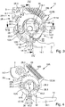
Fig. 1 bis 8 weiter ersichtlich ist, umfasst die erste Koppelvorrichtung 20 in den dargestellten Ausführungsbeispielen eine Stellvorrichtung 28, zwei erste Aussparungen 22A, welche an zwei vierten Koppelbereichen 12.2A der ersten Komponente 12A ausgebildet sind, zwei zweite Aussparungen 22B, welche fluchtend zu den zwei ersten Aussparungen 22A an zwei fünften Koppelbereichen 12.2B der zweiten Komponenten 12B der Drückernuss 12 ausgebildet sind, und zwei Koppelstifte 24, welche axial beweglich in den ersten Aussparungen 22A und/oder in den zweiten Aussparungen 22B geführt sind. - Wie insbesondere aus
Fig. 7 und 8 ersichtlich ist, sind die Koppelstifte 24 kürzer als eine Gesamtlänge fluchtend ausgerichteten ersten Aussparungen 22A und zweiten Aussparungen 22B ausgeführt. Wie ausFig. 7 weiter ersichtlich ist, sind die Koppelstifte 24 in einer dargestellten ersten axialen Endstellung vollständig in der zweiten Aussparung 22B der zweiten Komponente 12B der Drückernuss 12 angeordnet, so dass die erste Komponente 12A und die zweite Komponente 12B der Drückernuss 12 voneinander entkoppelt sind. Wie ausFig. 8 weiter ersichtlich ist, sind die Koppelstifte 24 in einer dargestellten zweiten axialen Endstellung in der ersten Aussparung 22A der ersten Komponente 12A und in der zweiten Aussparung 22B der zweiten Komponenten 12B der Drückernuss 12 angeordnet, so dass die erste Komponente 12A und die zweite Komponente 12B der Drückernuss 12 miteinander gekoppelt sind. - Wie aus
Fig. 1 bis 8 weiter ersichtlich ist, weist die Stellvorrichtung 28 einen als Ringsegment ausgeführten Grundkörper 28A auf, welcher im dargestellten Ausführungsbeispiel drehbeweglich mit der zweiten Komponente 12B der Drückernuss 12 verbunden ist. Hierzu wird der ringsegmentförmige Grundkörper 28A durch einen ringförmigen Kragen der zweiten Komponente 12B der Drückernuss 12 geführt. Bei den dargestellten Ausführungsbeispielen werden die beiden Koppelstifte 24 jeweils durch Magnetkraft bewegt. Daher sind die Koppelstifte 24 magnetisch ausgeführt. Zudem weist die Stellvorrichtung 28 vier Permanentmagnete 28.1, 28.2 auf, welche jeweils paarweise mit unterschiedlicher Polarität im Grundkörper 28A angeordnet sind. Hierbei sind die beiden Magnetpaar einander gegenüberliegend, d.h. mit einem Abstand von ca. 180°, am Grundkörper 28A angeordnet. Die beiden einzelnen Permanentmagnete 28.1, 28.2 der beiden Magnetpaare weisen im dargestellten Ausführungsbeispiel jeweils einen Abstand von ca. 20° zueinander auf. - Wie aus
Fig. 3 und7 weiter ersichtlich ist, ist in einer ersten Drehstellung des Grundkörpers 28A jeweils ein erster Permanentmagnet 28.1 über der korrespondierenden Aussparung 22B angeordnet und zieht den korrespondierenden magnetischen Koppelstift 24 an. Das bedeutet, dass die Polarisierung der ersten Permanentmagnete 28.1 so gewählt ist, dass in der ersten Drehstellung ungleiche Pole der Permanentmagnete 28.1 und der magnetischen Koppelstifte 24 einander zugewandt sind und sich anziehen. - Wie aus
Fig. 4 und8 weiter ersichtlich ist, ist in einer zweiten Drehstellung des Grundkörpers 28A jeweils ein zweiter Permanentmagnet 28.2 über der korrespondierenden Aussparung 22B angeordnet und stößt den korrespondierenden magnetischen Koppelstift 24 ab. Das bedeutet, dass die Polarisierung der zweiten Permanentmagnete 28.1 so gewählt ist, dass in der zweiten Drehstellung gleiche Pole der Permanentmagnete 28.1 und der magnetischen Koppelstifte 24 einander zugewandt sind und sich abstoßen. - Wie insbesondere aus
Fig. 7 und 8 weiter ersichtlich ist, sind die ersten Aussparungen 22A und die zweiten Aussparungen 22B jeweils als Sacklöcher ausgeführt. Hierbei bildet Böden der ersten Aussparungen 22A jeweils einen ersten Anschlag 26A und Böden der zweiten Aussparungen 22B jeweils einen zweiten Anschlag 26B für die Koppelstifte 24 aus. - Um den Grundkörper 28A zwischen der ersten und zweiten Drehstellung zu bewegen, weist der Grundkörper 28A umfangseitig bereichsweise ein Zahnsegment 28.3 auf, welches eine erste Verzahnung 9.1 eines Antriebszahnrads 9 kämmt. Wie insbesondere aus
Fig. 2 weiter ersichtlich ist, wirkt ein Elektromotor als Antrieb 5 über eine Spindel 7 auf eine zweite Verzahnung 9.2 des Antriebszahnrads 9 und bewegt den Grundkörper 28A der Stellvorrichtung 28 über das Zahnsegment 28.3 zwischen der ersten und zweiten Drehstellung. - Wie aus
Fig. 1 bis 8 weiter ersichtlich ist, weist die erste Komponente 12A in allen Ausführungsbeispielen einen Innenmehrkant 12.4 auf, welcher hier als Innenvierkant ausgeführt und direkt in die erste Komponente 12A der Drückernuss 12 eingebracht ist. Der Innenmehrkant 12.4 der ersten Komponente 12A der Drückernuss 12 kann zur Betätigung mit einem korrespondierenden Außenmehrkant des nicht dargestellten ersten Drückers gekoppelt werden. - Die zweite Komponente 12B weist in einem in
Fig. 1 bis 3 und5 bis 8 dargestellten ersten Ausführungsbeispiel der Druckernussanordnung 10 einen Innenmehrkant 16.1 auf, welcher hier als Innenvierkant ausgeführt und in einen Einsatz 16 eingebracht ist, welcher drehfest mit der zweiten Komponente 12B der Drückernuss 12 verbunden ist. Der Innenmehrkant 16.1 des Einsatzes 16 kann zur Betätigung mit einem korrespondierenden Außenmehrkant des nicht dargestellten zweiten Drückers gekoppelt werden. - Bei dem in
Fig. 1 bis 3 und5 bis 8 dargestellten ersten Ausführungsbeispiel der Druckernussanordnung 10 kann durch Software und eine entsprechende Energieversorgung bzw. Notversorgung über die erste Koppelvorrichtung 20 zwischen einem Fail-Safe-Betrieb, d.h. bei Stromausfall sind beide Drücker bzw. Komponenten 12A, 12B der Drückernuss 12 sowohl in Fluchtrichtung als auch in Gegenrichtung eingekoppelt, und einem Fail-Secure-Betrieb, d.h. bei Stromausfall ist nur der Drücker bzw. die Komponente 12A, 12B der Drückernuss 12 in Fluchtrichtung eingekoppelt, umgeschaltet werden. - Befindet sich das Stellelement 34 der zweiten Koppelvorrichtung 30 in der in
Fig. 5 dargestellten ersten axialen Endstellung, dann ist die erste Komponente 12A der Drückernuss 12 über das Stellelement 34 mit dem Betätigungselement 14 gekoppelt. Dadurch kann eine Betätigung des mit der ersten Komponente 12A der Drückernuss 12 gekoppelten ersten Drückers über die erste Komponente 12A und das Stellelement 34 auf das Betätigungselement 14 und auf den mit dem Betätigungselement 14 wirkverbundenen Riegel übertragen werden. Befinden sich die Koppelstifte 24 der ersten Koppelvorrichtung 20 in der inFig. 7 dargestellten ersten axialen Endstellung, dann sind die erste Komponente 12A und die zweite Komponente 12B der Drückernuss 12 voneinander entkoppelt, so dass eine Betätigung des mit der zweiten Komponente 12B der Drückernuss 12 gekoppelten zweiten Drückers keine Betätigung der Riegel bewirkt. Befinden sich die Koppelstifte 24 der ersten Koppelvorrichtung 20 in der inFig. 8 dargestellten zweiten axialen Endstellung, dann sind die erste Komponente 12A und die zweite Komponente 12B der Drückernuss 12 miteinander gekoppelt, so dass eine Betätigung des mit der zweiten Komponente 12B der Drückernuss 12 gekoppelten zweiten Drückers über die erste Koppelvorrichtung 20 auf die erste Komponente 12A der Drückernuss 12 und von dort über das Stellelement 34 auf das Betätigungselement 14 und den Riegel übertragen wird. So kann über den immer gekoppelten ersten Drücker eine Panikfunktion und über den koppelbaren zweiten Drücker eine Zugangsberechtigungsabfrage umgesetzt werden, so dass nur berechtigte Benutzer nach erfolgter Berechtigungsprüfung und entsprechende Steuersignale, welche auf den Antrieb 5 wirken, das Schloss 1 entriegeln können. - Befindet sich das Stellelement 34 der zweiten Koppelvorrichtung 30 in der in
Fig. 6 dargestellten zweiten axialen Endstellung, dann ist die zweite Komponente 12B der Drückernuss 12 über das Stellelement 34 mit dem Betätigungselement 14 gekoppelt. Dadurch kann eine Betätigung des mit der zweiten Komponente 12B der Drückernuss 12 gekoppelten zweiten Drückers über die zweite Komponente 12B und das Stellelement 34 auf das Betätigungselement 14 und auf den mit dem Betätigungselement 14 wirkverbundenen Riegel übertragen werden. Befinden sich die Koppelstifte 24 der ersten Koppelvorrichtung 20 in der inFig. 7 dargestellten ersten axialen Endstellung, dann sind die erste Komponente 12A und die zweite Komponente 12B der Drückernuss 12 voneinander entkoppelt, so dass eine Betätigung des mit der ersten Komponente 12A der Drückernuss 12 gekoppelten ersten Drückers keine Betätigung der Riegel bewirkt. Befinden sich die Koppelstifte 24 der ersten Koppelvorrichtung 20 in der inFig. 8 dargestellten zweiten axialen Endstellung, dann sind die erste Komponente 12A und die zweite Komponente 12B der Drückernuss 12 miteinander gekoppelt, so dass eine Betätigung des mit der ersten Komponente 12A der Drückernuss 12 gekoppelten zweiten Drückers über die erste Koppelvorrichtung 20 auf die zweite Komponente 12B der Drückernuss 12 und von dort über das Stellelement 34 auf das Betätigungselement 14 und den Riegel übertragen wird. So kann über den immer gekoppelten zweiten Drücker eine Panikfunktion und über den koppelbaren ersten Drücker eine Zugangsberechtigungsabfrage umgesetzt werden, so dass nur berechtigte Benutzer nach erfolgter Berechtigungsprüfung und entsprechende Steuersignale, welche auf den Antrieb 5 wirken, das Schloss 1 entriegeln können. - Bei einem in
Fig. 4 dargestellten zweiten Ausführungsbeispiel der Druckernussanordnung 10A ist der Einsatz 16 mit dem Innenmehrkant 16.1 entfernt und die zweite Komponente 12B der Drückernuss 12 weist keinen Innenmehrkant auf und kann daher nicht direkt betätigt werden. Zudem ist das Stellelement 34 in der inFig. 6 dargestellten zweiten axialen Endposition, so dass die zweite Komponente 12B der Drückernuss 12 über das Stellelement 34 mit dem Betätigungselement 14 gekoppelt ist. Bei dem dargestellten zweiten Ausführungsbeispiel kann über die erste Koppelvorrichtung 20 ein einkoppelbarer Drücker umgesetzt und aufgebaut werden. So können über die erste Koppelvorrichtung 20 und die Stellvorrichtung 28, welche über den Antrieb 5 angesteuert wird, die beiden Komponenten 12A, 12B der Drückernuss 12 miteinander gekoppelt werden. Der Grundkörper 28A der Stellvorrichtung 28 mit den Permanentmagneten 28.1, 28.2 muss nur um ca. 20° gedreht werden, um die nicht mit dem Betätigungselement 14 verbundene erste Komponente 12A der Drückernuss 12 mit der über das Stellelement 34 mit dem Betätigungselement 14 verbundenen zweiten Komponenten 12B der Drücknuss zu koppeln oder zu entkoppeln. - Befinden sich die Koppelstifte 24 der ersten Koppelvorrichtung in der in
Fig. 7 dargestellten ersten axialen Endstellung, dann sind die erste Komponente 12A und die zweite Komponente 12B der Drückernuss 12 voneinander entkoppelt, so dass eine Betätigung des mit der ersten Komponente 12A der Drückernuss 12 gekoppelten ersten Drückers keine Betätigung der Riegel bewirkt. Befinden sich die Koppelstifte 24 der ersten Koppelvorrichtung in der inFig. 8 dargestellten zweiten axialen Endstellung, dann sind die erste Komponente 12A und die zweite Komponente 12B der Drückernuss 12 miteinander gekoppelt, so dass eine Betätigung des mit der ersten Komponente 12A der Drückernuss 12 gekoppelten ersten Drückers über die erster Koppelvorrichtung 20 auf die zweite Komponenten 12B der Drückernuss 12 und von dort über das Stellelement 34 auf das Betätigungselement 14 übertragen wird. -
- 1
- Schloss
- 3
- Träger
- 5
- Antrieb
- 7
- Spindel
- 9
- Antriebszahnrad
- 9.1, 9.2
- Verzahnung
- 10, 10A
- Drückernussanordnung
- 12
- Drückernuss
- 12A, 12B
- Komponente
- 12.1A, 12.2A
- Koppelbereich
- 12.1B, 12.2B
- Koppelbereich
- 12.3A, 12.3B
- Federarm
- 12.4 erster
- Innenmehrkant
- 14
- Betätigungselement
- 14.1
- Betätigungsarm
- 14.2
- Ring
- 14.3
- Koppelbereich
- 16
- Einsatz
- 16.1
- zweiter Innenmehrkant
- 18A, 18B
- Rückstellfeder
- 20
- erste Koppelvorrichtung
- 22A, 22B
- Aussparung
- 24
- Koppelstift
- 26A, 26B
- Anschlag
- 28
- Stellvorrichtung
- 28A
- Grundkörper
- 28.1, 28.2
- Permanentmagnet
- 28.3
- Zahnsegment
- 30
- zweite Koppelvorrichtung
- 32
- Durchgangsöffnung
- 34
- Stellelement
- 34A
- Passstift
- 36A, 36B
- Anschlag
Claims (21)
- Drückernussanordnung (10, 10A) mit einer Drückernuss (12) und einem mit der Drückernuss (12) koppelbaren Betätigungselement (14), wobei die Drückernuss (12) eine drehbeweglich gelagerte erste Komponente (12A) und eine drehbeweglich gelagerte zweite Komponente (12B) umfasst, welche über eine erste Koppelvorrichtung (20) miteinander koppelbar sind,
dadurch gekennzeichnet,
dass eine zweite Koppelvorrichtung (30) die erste Komponente (12A) oder die zweite Komponente (12B) der Drückernuss (12) mit dem Betätigungselement (14) koppelt. - Drückernussanordnung (10, 10A) nach Anspruch 1,
dadurch gekennzeichnet,
dass die erste Komponente (12A) und die zweite Komponente (12B) der Drückernuss (12) jeweils ringförmig ausgeführt sind, wobei die erste Komponente (12A) mindestens einen ersten Koppelbereich (12.1A) und die zweite Komponente (12B) mindestens einen zweiten Koppelbereich (12.1B) umfasst. - Drückernussanordnung (10, 10A) nach Anspruch 1,
dadurch gekennzeichnet,
dass die erste Komponente (12A) und die zweite Komponente (12B) der Drückernuss (12) jeweils drehbeweglich gegen die Kraft einer Rückstellfeder (18A, 18B) gelagert sind. - Drückernussanordnung (10, 10A) nach einem der Ansprüche 1 bis 3,
dadurch gekennzeichnet,
dass das Betätigungselement (14) einen Betätigungsarm (14.1), einen drehbeweglich gelagerten Ring (14.2) und mindestens einen dritten Koppelbereich (14.3) umfasst, welcher den Betätigungsarm (14.1) mit dem Ring (14.2) verbindet. - Drückernussanordnung (10, 10A) nach Anspruch 4,
dadurch gekennzeichnet,
dass zumindest der dritte Koppelbereich (14.3) des Betätigungselements (14) zwischen dem ersten Koppelbereich (12.1A) der ersten Komponente (12A) und dem zweiten Koppelbereich (12.1B) der zweiten Komponente (12B) der Drückernuss (12) angeordnet ist. - Drückernussanordnung (10, 10A) nach Anspruch 5,
dadurch gekennzeichnet,
dass die zweite Koppelvorrichtung (30) eine Durchgangsöffnung (32), welche den ersten Koppelbereich (12.1A), den zweiten Koppelbereich (12.1B) und den dritten Koppelbereich (14.3) durchdringt, und ein in der Durchgangsöffnung (32) axial geführtes Stellelement (34) umfasst, welches mit einem vorgebbaren Kraftaufwand in der Durchgangsöffnung (32) manuell bewegbar ist. - Drückernussanordnung (10, 10A) nach Anspruch 6,
dadurch gekennzeichnet,
dass das Stellelement (34) kürzer als die Durchgangsbohrung (32) ausgeführt ist, wobei das Stellelement (34) in einer ersten axialen Endstellung nur den ersten Koppelbereich (12.1A) und den dritten Koppelbereich (14.3) und in einer zweiten axialen Endstellung nur den dritten Koppelbereich (14.3) und den zweiten Koppelbereich (12.1B) durchdringt. - Drückernussanordnung (10, 10A) nach Anspruch 7,
dadurch gekennzeichnet,
dass das Stellelement (34) in der ersten axialen Endstellung an einem im ersten Koppelbereich (12.1A) ausgebildeten ersten Anschlag (36A) und in der zweiten axialen Endstellung an einem im zweiten Koppelbereich (12.1B) ausgebildeten zweiten Anschlag (36B) anliegt. - Drückernussanordnung (10, 10A) nach einem der Ansprüche 6 bis 8,
dadurch gekennzeichnet,
dass das Stellelement (34) als Pressstift (34A) oder als Madenschraube oder als Kerbstift ausgeführt ist. - Drückernussanordnung (10, 10A) nach einem der Ansprüche 1 bis 9,
dadurch gekennzeichnet,
dass die erste Koppelvorrichtung (20) eine Stellvorrichtung (28), mindestens eine erste Aussparung (22A), welche an mindestens einem vierten Koppelbereich (12.2A) der ersten Komponente (12A) ausgebildet ist, mindestens eine zweite Aussparung (22B), welche fluchtend zur mindestens einen ersten Aussparung (22A) an mindestens einem fünften Koppelbereich (12.2B) der zweiten Komponente (12B) der Drückernuss (12) ausgebildet ist, und mindestens einen Koppelstift (24) umfasst, welcher axial beweglich in der ersten Aussparung (22A) und/oder in der zweiten Aussparung (22B) geführt ist. - Drückernussanordnung (10, 10A) nach Anspruch 10,
dadurch gekennzeichnet,
dass der mindestens eine Koppelstift (24) kürzer als eine Gesamtlänge der ersten Aussparung (22A) und der zweiten Aussparung (22B) ausgeführt ist, wobei der mindestens eine Koppelstift (24) in einer ersten axialen Endstellung vollständig in der ersten Aussparung (22A) oder in der zweiten Aussparung (22B) angeordnet ist und in einer zweiten axialen Endstellung in der ersten Aussparung (22A) und in der zweiten Aussparung (22B) angeordnet ist. - Drückernussanordnung (10, 10A) nach Anspruch 10 oder 11,
dadurch gekennzeichnet,
dass die Stellvorrichtung (28) einen als Ringsegment ausgeführten Grundkörper (28A) aufweist, welcher drehbeweglich mit der ersten Komponente (12A) oder mit der zweiten Komponente (12B) der Drückernuss (12) verbunden ist. - Drückernussanordnung (10, 10A) nach einem der Ansprüche 10 bis 12,
dadurch gekennzeichnet,
dass der mindestens eine Koppelstift (24) durch Magnetkraft bewegbar ist. - Drückernussanordnung (10, 10A) nach Anspruch 13,
dadurch gekennzeichnet,
dass der mindestens eine Koppelstift (24) magnetisch ausgeführt ist und die Stellvorrichtung (28) mindestens zwei Permanentmagnete (28.1, 28.2) aufweist, welche mit unterschiedlicher Polarität im Grundkörper (28A) angeordnet sind. - Drückernussanordnung (10, 10A) nach Anspruch 14,
dadurch gekennzeichnet,
dass in einer ersten Drehstellung des Grundkörpers (28A) ein erster Permanentmagnet (28.1) über der korrespondierenden Aussparung (22A, 22B) angeordnet ist und den mindestens einen magnetischen Koppelstift (24) anzieht, und in einer zweiten Drehstellung des Grundkörpers (28A) ein zweiter Permanentmagnet (28.2) der korrespondierenden Aussparung (22A, 22B) angeordnet ist und den mindestens einen magnetischen Koppelstift (24) abstößt. - Drückernussanordnung (10, 10A) nach Anspruch 15,
dadurch gekennzeichnet,
dass der Grundkörper (28A) umfangseitig bereichsweise ein Zahnsegment (28.3) aufweist, welches eine Verzahnung (9.1) eines Antriebszahnrads (9) kämmt, um den Grundkörper (28A) zwischen der ersten und zweiten Drehstellung zu bewegen. - Drückernussanordnung (10, 10A) nach einem der Ansprüche 1 bis 16,
dadurch gekennzeichnet,
dass die erste Komponente (12A) und/oder die zweite Komponente (12B) einen Innenmehrkant (12.4, 16.1) aufweisen, welcher zur Betätigung mit einem korrespondierenden Außenmehrkant eines ersten Drückers oder eines zweiten Drückers koppelbar ist. - Drückernussanordnung (10, 10A) nach Anspruch 17,
dadurch gekennzeichnet,
dass der Innenmehrkant (12.4, 16.1) direkt in die korrespondierende Komponente (12A) oder in einen Einsatz (16) eingebracht ist, welcher drehfest mit der korrespondierenden Komponente (12B) verbunden ist. - Schloss (1) mit einem Schlossgehäuse, einem Stulpblech, mindestens einem Riegel, mindestens einer Falle und einer über mindestens einen Drücker betätigbare Drückernussanordnung (10, 10A),
dadurch gekennzeichnet, dass die Drückernussanordnung (10, 10A) nach zumindest einem der Patentansprüche 1 bis 18 ausgeführt ist. - Schloss (1) nach Anspruch 19,
dadurch gekennzeichnet,
dass das Stellelement (34) bei einem DIN-rechts-Schloss in die erste axiale Endstellung und bei einem DIN-links-Schloss in die zweite axiale Endstellung überführt ist. - Schloss (1) nach Anspruch 19 oder 20,
dadurch gekennzeichnet,
dass ein Elektromotor als Antrieb (5) über eine Spindel (7) auf das Antriebszahnrad (9) wirkt und den Grundkörper (28A) der Stellvorrichtung (28) über das Zahnsegment (28.3) zwischen der ersten und zweiten Drehstellung bewegt.
Priority Applications (1)
| Application Number | Priority Date | Filing Date | Title |
|---|---|---|---|
| PL18171415T PL3412851T3 (pl) | 2017-06-08 | 2018-05-09 | Układ orzecha klamki do zamka |
Applications Claiming Priority (1)
| Application Number | Priority Date | Filing Date | Title |
|---|---|---|---|
| DE102017209634.9A DE102017209634A1 (de) | 2017-06-08 | 2017-06-08 | Drückernussanordnung für ein Schloss |
Publications (2)
| Publication Number | Publication Date |
|---|---|
| EP3412851A1 true EP3412851A1 (de) | 2018-12-12 |
| EP3412851B1 EP3412851B1 (de) | 2021-06-23 |
Family
ID=62148143
Family Applications (1)
| Application Number | Title | Priority Date | Filing Date |
|---|---|---|---|
| EP18171415.5A Active EP3412851B1 (de) | 2017-06-08 | 2018-05-09 | Drückernussanordnung für ein schloss |
Country Status (4)
| Country | Link |
|---|---|
| EP (1) | EP3412851B1 (de) |
| CN (1) | CN109025489B (de) |
| DE (1) | DE102017209634A1 (de) |
| PL (1) | PL3412851T3 (de) |
Families Citing this family (1)
| Publication number | Priority date | Publication date | Assignee | Title |
|---|---|---|---|---|
| DE102021203025A1 (de) | 2021-03-26 | 2022-08-11 | Geze Gmbh | Türschlosssystem, Tür und Verfahren zum Steuern eines Türschlosssystems |
Citations (3)
| Publication number | Priority date | Publication date | Assignee | Title |
|---|---|---|---|---|
| DE69408012T2 (de) * | 1993-03-24 | 1998-08-13 | Italiana Serrature Affini | Schloss für Notausgang, anpassbar an die Türöffnungsrichtung, mit einer Handhabe auf der einen Seite und eine Möglichkeit zum befristeten Öffnen auf der anderen Seite |
| US20100225126A1 (en) * | 2009-03-06 | 2010-09-09 | Tong Lung Metal Industry Co., Ltd. | Latch-bolt mechanism operable to allow for idle rotation of an exterior handle |
| DE102015210948A1 (de) | 2015-06-15 | 2016-12-15 | Geze Gmbh | Schloss |
Family Cites Families (5)
| Publication number | Priority date | Publication date | Assignee | Title |
|---|---|---|---|---|
| CN2489044Y (zh) * | 2001-07-19 | 2002-05-01 | 昆明金安利信息技术有限公司 | 一种可实现左右开门功能的锁芯机构 |
| CN2551729Y (zh) * | 2002-06-28 | 2003-05-21 | 昆明金安利信息技术有限公司 | 一种可实现左内、左外、右内、右外开门的锁芯机构 |
| FI115479B (fi) * | 2003-10-30 | 2005-05-13 | Abloy Oy | Ohjattavalla painiketoiminnolla varustettu ovenlukko |
| DE102011000552A1 (de) * | 2011-02-08 | 2012-08-09 | Dorma Gmbh + Co. Kg | Schaltbare Drückernuss für ein Türschloss |
| DE102014004136A1 (de) * | 2014-03-24 | 2015-09-24 | Kfv Karl Fliether Gmbh & Co. Kg | Verfahren zum Betrieb eines Panikschlosses |
-
2017
- 2017-06-08 DE DE102017209634.9A patent/DE102017209634A1/de not_active Withdrawn
-
2018
- 2018-05-09 PL PL18171415T patent/PL3412851T3/pl unknown
- 2018-05-09 EP EP18171415.5A patent/EP3412851B1/de active Active
- 2018-06-08 CN CN201810583264.2A patent/CN109025489B/zh active Active
Patent Citations (3)
| Publication number | Priority date | Publication date | Assignee | Title |
|---|---|---|---|---|
| DE69408012T2 (de) * | 1993-03-24 | 1998-08-13 | Italiana Serrature Affini | Schloss für Notausgang, anpassbar an die Türöffnungsrichtung, mit einer Handhabe auf der einen Seite und eine Möglichkeit zum befristeten Öffnen auf der anderen Seite |
| US20100225126A1 (en) * | 2009-03-06 | 2010-09-09 | Tong Lung Metal Industry Co., Ltd. | Latch-bolt mechanism operable to allow for idle rotation of an exterior handle |
| DE102015210948A1 (de) | 2015-06-15 | 2016-12-15 | Geze Gmbh | Schloss |
Also Published As
| Publication number | Publication date |
|---|---|
| EP3412851B1 (de) | 2021-06-23 |
| DE102017209634A1 (de) | 2018-12-13 |
| CN109025489B (zh) | 2021-01-26 |
| CN109025489A (zh) | 2018-12-18 |
| PL3412851T3 (pl) | 2021-12-06 |
Similar Documents
| Publication | Publication Date | Title |
|---|---|---|
| EP1636454B1 (de) | Elektromechanischer schliesszylinder | |
| EP1214491B1 (de) | Sperreinrichtung für ein zylinderschloss | |
| EP3363972B1 (de) | Elektrisch schaltbare zuhaltevorrichtung für eine türanlage | |
| DE3632904C2 (de) | ||
| EP2302149B1 (de) | Betätigungsvorrichtung, bspw. Schließzylinder oder Türdrückergarnitur mit von einem Schaltglied magnetisch verlagerbaren Umschaltglied | |
| DE102006024685A1 (de) | Elektromechanisches, durch Drücken verschließbares Schloss | |
| WO2004057137A1 (de) | Verriegelungsvorrichtung | |
| DE102010018243B4 (de) | Schließzylinderanordnung | |
| EP0819810B1 (de) | Beschlag für ein Schloss | |
| EP1662076B1 (de) | Kupplungsvorrichtung für eine Verriegelungstechnik | |
| DE3914751A1 (de) | Beschlag, insbesondere fuer tueren oder dergleichen | |
| EP1984932B1 (de) | Schlüsseltransferschalter system und methode | |
| DE19754923C1 (de) | Türbeschlag | |
| EP1722049A2 (de) | Elektromechanisches Schliesssystem | |
| DE19604442A1 (de) | Sicherheitsvorrichtung für elektronische Schlösser | |
| DE102007011554B4 (de) | Koppeleinheit für elektronische Schließ-Systeme | |
| DE10235201A1 (de) | Türschließystem | |
| DE10324690A1 (de) | Ferngesteuert freigebbarer Schließzylinder | |
| EP3412851B1 (de) | Drückernussanordnung für ein schloss | |
| EP2345782A1 (de) | Anti-Panik-Zylinder | |
| DE10225649B4 (de) | Ferngesteuert freigebbarer Schließzylinder | |
| DE102013212508A1 (de) | Türanlage | |
| DE10163355C1 (de) | Schließzylinder, insbesondere für ein Einsteckschloss | |
| EP0623721A1 (de) | Schlossanordnung | |
| EP1505229B1 (de) | Schliesszylinder |
Legal Events
| Date | Code | Title | Description |
|---|---|---|---|
| PUAI | Public reference made under article 153(3) epc to a published international application that has entered the european phase |
Free format text: ORIGINAL CODE: 0009012 |
|
| STAA | Information on the status of an ep patent application or granted ep patent |
Free format text: STATUS: THE APPLICATION HAS BEEN PUBLISHED |
|
| AK | Designated contracting states |
Kind code of ref document: A1 Designated state(s): AL AT BE BG CH CY CZ DE DK EE ES FI FR GB GR HR HU IE IS IT LI LT LU LV MC MK MT NL NO PL PT RO RS SE SI SK SM TR |
|
| AX | Request for extension of the european patent |
Extension state: BA ME |
|
| STAA | Information on the status of an ep patent application or granted ep patent |
Free format text: STATUS: REQUEST FOR EXAMINATION WAS MADE |
|
| 17P | Request for examination filed |
Effective date: 20190515 |
|
| RBV | Designated contracting states (corrected) |
Designated state(s): AL AT BE BG CH CY CZ DE DK EE ES FI FR GB GR HR HU IE IS IT LI LT LU LV MC MK MT NL NO PL PT RO RS SE SI SK SM TR |
|
| STAA | Information on the status of an ep patent application or granted ep patent |
Free format text: STATUS: EXAMINATION IS IN PROGRESS |
|
| 17Q | First examination report despatched |
Effective date: 20200507 |
|
| GRAP | Despatch of communication of intention to grant a patent |
Free format text: ORIGINAL CODE: EPIDOSNIGR1 |
|
| STAA | Information on the status of an ep patent application or granted ep patent |
Free format text: STATUS: GRANT OF PATENT IS INTENDED |
|
| RIC1 | Information provided on ipc code assigned before grant |
Ipc: E05B 47/00 20060101ALN20201216BHEP Ipc: E05B 63/04 20060101ALI20201216BHEP Ipc: E05B 47/06 20060101AFI20201216BHEP |
|
| INTG | Intention to grant announced |
Effective date: 20210114 |
|
| GRAS | Grant fee paid |
Free format text: ORIGINAL CODE: EPIDOSNIGR3 |
|
| GRAA | (expected) grant |
Free format text: ORIGINAL CODE: 0009210 |
|
| STAA | Information on the status of an ep patent application or granted ep patent |
Free format text: STATUS: THE PATENT HAS BEEN GRANTED |
|
| AK | Designated contracting states |
Kind code of ref document: B1 Designated state(s): AL AT BE BG CH CY CZ DE DK EE ES FI FR GB GR HR HU IE IS IT LI LT LU LV MC MK MT NL NO PL PT RO RS SE SI SK SM TR |
|
| REG | Reference to a national code |
Ref country code: GB Ref legal event code: FG4D Free format text: NOT ENGLISH |
|
| REG | Reference to a national code |
Ref country code: CH Ref legal event code: EP |
|
| REG | Reference to a national code |
Ref country code: DE Ref legal event code: R096 Ref document number: 502018005790 Country of ref document: DE Ref country code: AT Ref legal event code: REF Ref document number: 1404459 Country of ref document: AT Kind code of ref document: T Effective date: 20210715 |
|
| REG | Reference to a national code |
Ref country code: IE Ref legal event code: FG4D Free format text: LANGUAGE OF EP DOCUMENT: GERMAN |
|
| REG | Reference to a national code |
Ref country code: LT Ref legal event code: MG9D |
|
| PG25 | Lapsed in a contracting state [announced via postgrant information from national office to epo] |
Ref country code: BG Free format text: LAPSE BECAUSE OF FAILURE TO SUBMIT A TRANSLATION OF THE DESCRIPTION OR TO PAY THE FEE WITHIN THE PRESCRIBED TIME-LIMIT Effective date: 20210923 Ref country code: HR Free format text: LAPSE BECAUSE OF FAILURE TO SUBMIT A TRANSLATION OF THE DESCRIPTION OR TO PAY THE FEE WITHIN THE PRESCRIBED TIME-LIMIT Effective date: 20210623 Ref country code: LT Free format text: LAPSE BECAUSE OF FAILURE TO SUBMIT A TRANSLATION OF THE DESCRIPTION OR TO PAY THE FEE WITHIN THE PRESCRIBED TIME-LIMIT Effective date: 20210623 Ref country code: FI Free format text: LAPSE BECAUSE OF FAILURE TO SUBMIT A TRANSLATION OF THE DESCRIPTION OR TO PAY THE FEE WITHIN THE PRESCRIBED TIME-LIMIT Effective date: 20210623 |
|
| PG25 | Lapsed in a contracting state [announced via postgrant information from national office to epo] |
Ref country code: NO Free format text: LAPSE BECAUSE OF FAILURE TO SUBMIT A TRANSLATION OF THE DESCRIPTION OR TO PAY THE FEE WITHIN THE PRESCRIBED TIME-LIMIT Effective date: 20210923 Ref country code: LV Free format text: LAPSE BECAUSE OF FAILURE TO SUBMIT A TRANSLATION OF THE DESCRIPTION OR TO PAY THE FEE WITHIN THE PRESCRIBED TIME-LIMIT Effective date: 20210623 Ref country code: RS Free format text: LAPSE BECAUSE OF FAILURE TO SUBMIT A TRANSLATION OF THE DESCRIPTION OR TO PAY THE FEE WITHIN THE PRESCRIBED TIME-LIMIT Effective date: 20210623 Ref country code: SE Free format text: LAPSE BECAUSE OF FAILURE TO SUBMIT A TRANSLATION OF THE DESCRIPTION OR TO PAY THE FEE WITHIN THE PRESCRIBED TIME-LIMIT Effective date: 20210623 Ref country code: GR Free format text: LAPSE BECAUSE OF FAILURE TO SUBMIT A TRANSLATION OF THE DESCRIPTION OR TO PAY THE FEE WITHIN THE PRESCRIBED TIME-LIMIT Effective date: 20210924 |
|
| REG | Reference to a national code |
Ref country code: NL Ref legal event code: FP |
|
| PG25 | Lapsed in a contracting state [announced via postgrant information from national office to epo] |
Ref country code: SM Free format text: LAPSE BECAUSE OF FAILURE TO SUBMIT A TRANSLATION OF THE DESCRIPTION OR TO PAY THE FEE WITHIN THE PRESCRIBED TIME-LIMIT Effective date: 20210623 Ref country code: SK Free format text: LAPSE BECAUSE OF FAILURE TO SUBMIT A TRANSLATION OF THE DESCRIPTION OR TO PAY THE FEE WITHIN THE PRESCRIBED TIME-LIMIT Effective date: 20210623 Ref country code: ES Free format text: LAPSE BECAUSE OF FAILURE TO SUBMIT A TRANSLATION OF THE DESCRIPTION OR TO PAY THE FEE WITHIN THE PRESCRIBED TIME-LIMIT Effective date: 20210623 Ref country code: EE Free format text: LAPSE BECAUSE OF FAILURE TO SUBMIT A TRANSLATION OF THE DESCRIPTION OR TO PAY THE FEE WITHIN THE PRESCRIBED TIME-LIMIT Effective date: 20210623 Ref country code: CZ Free format text: LAPSE BECAUSE OF FAILURE TO SUBMIT A TRANSLATION OF THE DESCRIPTION OR TO PAY THE FEE WITHIN THE PRESCRIBED TIME-LIMIT Effective date: 20210623 Ref country code: PT Free format text: LAPSE BECAUSE OF FAILURE TO SUBMIT A TRANSLATION OF THE DESCRIPTION OR TO PAY THE FEE WITHIN THE PRESCRIBED TIME-LIMIT Effective date: 20211025 Ref country code: RO Free format text: LAPSE BECAUSE OF FAILURE TO SUBMIT A TRANSLATION OF THE DESCRIPTION OR TO PAY THE FEE WITHIN THE PRESCRIBED TIME-LIMIT Effective date: 20210623 |
|
| REG | Reference to a national code |
Ref country code: DE Ref legal event code: R097 Ref document number: 502018005790 Country of ref document: DE |
|
| PG25 | Lapsed in a contracting state [announced via postgrant information from national office to epo] |
Ref country code: DK Free format text: LAPSE BECAUSE OF FAILURE TO SUBMIT A TRANSLATION OF THE DESCRIPTION OR TO PAY THE FEE WITHIN THE PRESCRIBED TIME-LIMIT Effective date: 20210623 |
|
| PLBE | No opposition filed within time limit |
Free format text: ORIGINAL CODE: 0009261 |
|
| STAA | Information on the status of an ep patent application or granted ep patent |
Free format text: STATUS: NO OPPOSITION FILED WITHIN TIME LIMIT |
|
| 26N | No opposition filed |
Effective date: 20220324 |
|
| PG25 | Lapsed in a contracting state [announced via postgrant information from national office to epo] |
Ref country code: AL Free format text: LAPSE BECAUSE OF FAILURE TO SUBMIT A TRANSLATION OF THE DESCRIPTION OR TO PAY THE FEE WITHIN THE PRESCRIBED TIME-LIMIT Effective date: 20210623 |
|
| PG25 | Lapsed in a contracting state [announced via postgrant information from national office to epo] |
Ref country code: IT Free format text: LAPSE BECAUSE OF FAILURE TO SUBMIT A TRANSLATION OF THE DESCRIPTION OR TO PAY THE FEE WITHIN THE PRESCRIBED TIME-LIMIT Effective date: 20210623 |
|
| GBPC | Gb: european patent ceased through non-payment of renewal fee |
Effective date: 20220509 |
|
| PG25 | Lapsed in a contracting state [announced via postgrant information from national office to epo] |
Ref country code: MC Free format text: LAPSE BECAUSE OF FAILURE TO SUBMIT A TRANSLATION OF THE DESCRIPTION OR TO PAY THE FEE WITHIN THE PRESCRIBED TIME-LIMIT Effective date: 20210623 |
|
| PG25 | Lapsed in a contracting state [announced via postgrant information from national office to epo] |
Ref country code: IE Free format text: LAPSE BECAUSE OF NON-PAYMENT OF DUE FEES Effective date: 20220509 |
|
| PG25 | Lapsed in a contracting state [announced via postgrant information from national office to epo] |
Ref country code: GB Free format text: LAPSE BECAUSE OF NON-PAYMENT OF DUE FEES Effective date: 20220509 |
|
| P01 | Opt-out of the competence of the unified patent court (upc) registered |
Effective date: 20230510 |
|
| PGFP | Annual fee paid to national office [announced via postgrant information from national office to epo] |
Ref country code: LU Payment date: 20230519 Year of fee payment: 6 |
|
| PGFP | Annual fee paid to national office [announced via postgrant information from national office to epo] |
Ref country code: NL Payment date: 20230519 Year of fee payment: 6 Ref country code: FR Payment date: 20230526 Year of fee payment: 6 Ref country code: DE Payment date: 20230531 Year of fee payment: 6 Ref country code: CH Payment date: 20230605 Year of fee payment: 6 |
|
| PGFP | Annual fee paid to national office [announced via postgrant information from national office to epo] |
Ref country code: PL Payment date: 20230428 Year of fee payment: 6 Ref country code: AT Payment date: 20230522 Year of fee payment: 6 |
|
| PGFP | Annual fee paid to national office [announced via postgrant information from national office to epo] |
Ref country code: BE Payment date: 20230519 Year of fee payment: 6 |
|
| PG25 | Lapsed in a contracting state [announced via postgrant information from national office to epo] |
Ref country code: HU Free format text: LAPSE BECAUSE OF FAILURE TO SUBMIT A TRANSLATION OF THE DESCRIPTION OR TO PAY THE FEE WITHIN THE PRESCRIBED TIME-LIMIT; INVALID AB INITIO Effective date: 20180509 |
|
| PG25 | Lapsed in a contracting state [announced via postgrant information from national office to epo] |
Ref country code: MK Free format text: LAPSE BECAUSE OF FAILURE TO SUBMIT A TRANSLATION OF THE DESCRIPTION OR TO PAY THE FEE WITHIN THE PRESCRIBED TIME-LIMIT Effective date: 20210623 Ref country code: CY Free format text: LAPSE BECAUSE OF FAILURE TO SUBMIT A TRANSLATION OF THE DESCRIPTION OR TO PAY THE FEE WITHIN THE PRESCRIBED TIME-LIMIT Effective date: 20210623 |