EP3412366A2 - Rapid heating tip for a hot-melt glue gun and a hot-melt glue gun - Google Patents
Rapid heating tip for a hot-melt glue gun and a hot-melt glue gun Download PDFInfo
- Publication number
- EP3412366A2 EP3412366A2 EP18176705.4A EP18176705A EP3412366A2 EP 3412366 A2 EP3412366 A2 EP 3412366A2 EP 18176705 A EP18176705 A EP 18176705A EP 3412366 A2 EP3412366 A2 EP 3412366A2
- Authority
- EP
- European Patent Office
- Prior art keywords
- hot
- glue
- gun
- melt glue
- rapid heating
- Prior art date
- Legal status (The legal status is an assumption and is not a legal conclusion. Google has not performed a legal analysis and makes no representation as to the accuracy of the status listed.)
- Granted
Links
- 239000003292 glue Substances 0.000 title claims abstract description 118
- 238000010438 heat treatment Methods 0.000 title claims abstract description 115
- 239000012943 hotmelt Substances 0.000 title claims abstract description 70
- 230000007704 transition Effects 0.000 claims abstract description 71
- 239000004836 Glue Stick Substances 0.000 claims description 35
- 238000005520 cutting process Methods 0.000 claims description 31
- 229910052782 aluminium Inorganic materials 0.000 claims description 7
- XAGFODPZIPBFFR-UHFFFAOYSA-N aluminium Chemical compound [Al] XAGFODPZIPBFFR-UHFFFAOYSA-N 0.000 claims description 7
- 239000004020 conductor Substances 0.000 claims description 4
- 239000000463 material Substances 0.000 description 4
- 239000000155 melt Substances 0.000 description 3
- 238000002844 melting Methods 0.000 description 3
- 230000008018 melting Effects 0.000 description 3
- 239000012141 concentrate Substances 0.000 description 2
- 230000003247 decreasing effect Effects 0.000 description 2
- 230000000694 effects Effects 0.000 description 2
- 238000004519 manufacturing process Methods 0.000 description 2
- 239000007769 metal material Substances 0.000 description 2
- 230000002411 adverse Effects 0.000 description 1
- 238000013459 approach Methods 0.000 description 1
- 230000008859 change Effects 0.000 description 1
- 238000004891 communication Methods 0.000 description 1
- 230000001419 dependent effect Effects 0.000 description 1
- 238000010586 diagram Methods 0.000 description 1
- 238000009826 distribution Methods 0.000 description 1
- 230000002708 enhancing effect Effects 0.000 description 1
- 239000002360 explosive Substances 0.000 description 1
- 239000007788 liquid Substances 0.000 description 1
- 229910052751 metal Inorganic materials 0.000 description 1
- 239000002184 metal Substances 0.000 description 1
- 150000002739 metals Chemical class 0.000 description 1
- 238000000034 method Methods 0.000 description 1
- 238000012986 modification Methods 0.000 description 1
- 230000004048 modification Effects 0.000 description 1
- 238000007254 oxidation reaction Methods 0.000 description 1
- 230000008569 process Effects 0.000 description 1
- 238000012545 processing Methods 0.000 description 1
- 230000004044 response Effects 0.000 description 1
- 239000007787 solid Substances 0.000 description 1
- 238000003466 welding Methods 0.000 description 1
Images


Classifications
-
- B—PERFORMING OPERATIONS; TRANSPORTING
- B05—SPRAYING OR ATOMISING IN GENERAL; APPLYING FLUENT MATERIALS TO SURFACES, IN GENERAL
- B05C—APPARATUS FOR APPLYING FLUENT MATERIALS TO SURFACES, IN GENERAL
- B05C17/00—Hand tools or apparatus using hand held tools, for applying liquids or other fluent materials to, for spreading applied liquids or other fluent materials on, or for partially removing applied liquids or other fluent materials from, surfaces
- B05C17/005—Hand tools or apparatus using hand held tools, for applying liquids or other fluent materials to, for spreading applied liquids or other fluent materials on, or for partially removing applied liquids or other fluent materials from, surfaces for discharging material from a reservoir or container located in or on the hand tool through an outlet orifice by pressure without using surface contacting members like pads or brushes
- B05C17/00523—Hand tools or apparatus using hand held tools, for applying liquids or other fluent materials to, for spreading applied liquids or other fluent materials on, or for partially removing applied liquids or other fluent materials from, surfaces for discharging material from a reservoir or container located in or on the hand tool through an outlet orifice by pressure without using surface contacting members like pads or brushes provided with means to heat the material
- B05C17/00546—Details of the heating means
-
- B—PERFORMING OPERATIONS; TRANSPORTING
- B05—SPRAYING OR ATOMISING IN GENERAL; APPLYING FLUENT MATERIALS TO SURFACES, IN GENERAL
- B05C—APPARATUS FOR APPLYING FLUENT MATERIALS TO SURFACES, IN GENERAL
- B05C17/00—Hand tools or apparatus using hand held tools, for applying liquids or other fluent materials to, for spreading applied liquids or other fluent materials on, or for partially removing applied liquids or other fluent materials from, surfaces
- B05C17/005—Hand tools or apparatus using hand held tools, for applying liquids or other fluent materials to, for spreading applied liquids or other fluent materials on, or for partially removing applied liquids or other fluent materials from, surfaces for discharging material from a reservoir or container located in or on the hand tool through an outlet orifice by pressure without using surface contacting members like pads or brushes
- B05C17/0052—Accessories therefor
-
- B—PERFORMING OPERATIONS; TRANSPORTING
- B05—SPRAYING OR ATOMISING IN GENERAL; APPLYING FLUENT MATERIALS TO SURFACES, IN GENERAL
- B05C—APPARATUS FOR APPLYING FLUENT MATERIALS TO SURFACES, IN GENERAL
- B05C17/00—Hand tools or apparatus using hand held tools, for applying liquids or other fluent materials to, for spreading applied liquids or other fluent materials on, or for partially removing applied liquids or other fluent materials from, surfaces
- B05C17/005—Hand tools or apparatus using hand held tools, for applying liquids or other fluent materials to, for spreading applied liquids or other fluent materials on, or for partially removing applied liquids or other fluent materials from, surfaces for discharging material from a reservoir or container located in or on the hand tool through an outlet orifice by pressure without using surface contacting members like pads or brushes
- B05C17/00523—Hand tools or apparatus using hand held tools, for applying liquids or other fluent materials to, for spreading applied liquids or other fluent materials on, or for partially removing applied liquids or other fluent materials from, surfaces for discharging material from a reservoir or container located in or on the hand tool through an outlet orifice by pressure without using surface contacting members like pads or brushes provided with means to heat the material
- B05C17/00526—Hand tools or apparatus using hand held tools, for applying liquids or other fluent materials to, for spreading applied liquids or other fluent materials on, or for partially removing applied liquids or other fluent materials from, surfaces for discharging material from a reservoir or container located in or on the hand tool through an outlet orifice by pressure without using surface contacting members like pads or brushes provided with means to heat the material the material being supplied to the apparatus in a solid state, e.g. rod, and melted before application
Definitions
- the present disclosure relates to the field of electric power tools, and more particularly relates to a rapid heating tip for a hot-melt glue gun.
- a hot-melt glue gun is a tool that melts a solid hot-melt glue stick into a liquid-state glue by electrical heating and applies the glue liquid to an object surface which needs to be bonded; due to its small size, convenience to carry, and flexibility to use, the hot-melt glue gun is a common glue squeezing tool for individuals, households, and factories. Glue jetting speed is an important performance indicator of hot-melt glue guns.
- a hot-melt glue gun uses a PTC heating sheet to heat a melt glue tube to melt the glue; a power cord is connected to the PTC electrodes, respectively; and a heating body is formed after wrapping the PTC with an insulative material. Due to wrapping with the insulative material outside of the PTC heating sheet, this solution has drawbacks such as a low heat conduction efficiency and a long heating time, which generally takes 3 ⁇ 5 minutes or even longer.
- the present disclosure provides a rapid heating gun tip for a hot-melt glue gun, which addresses the issues of low heat conduction efficiency and long heating time.
- a rapid heating gun tip for a hot-melt glue gun comprising a glue loading sleeve and a glue jetting nozzle, a transition tube being formed between the glue jetting nozzle and the glue loading sleeve; wherein the rapid heating gun tip for a hot-melt glue gun further comprising an electrode sheet and a plurality of heating bodies, the transition tube having a plurality of heat conduction planes, the heat conduction planes being inclined relative to an axial line of the glue loading sleeve, and the electrode sheets tightly press-fitting the heating bodies against outer sides of the heat conduction planes.
- the heating body is a PTC heating sheet.
- the rapid heating gun tip for a hot-melt glue gun further comprises a connecting sheet, wherein the transition tube is a conductor, and the transition tube is connected to an external wire via the connecting sheet.
- the transition tube is an aluminum tube.
- the rapid heating gun tip for a hot-melt glue gun further comprises a heat insulating sheath in which the electrode sheet, the heating body and the transition tube are accommodated.
- the rapid heating gun tip for a hot-melt glue gun further comprises a cutter, the cutter being disposed in the transition tube to axially cut a glue stick, the transition tube and the cutter conducting heat to facilitate the cutter to heat the cut glue stick.
- the cutter comprises at least two cutting blades distributed in a radial mode, radial inner ends of the at least two cutting blades being interconnected and converged at a central axis of the transition tube, and radial outer ends of the at least two cutting blades conducting heat with the transition tube.
- a side of the cutting blade distant from the glue jetting nozzle is thinned to form a cutting edge.
- the cutter and the transition tube are integrally formed; or the cutter and the transition tube are separately formed, the cutter being fixedly mounted in the transition tube.
- the present disclosure further provides a hot-melt glue gun, comprising a rapid heating gun tip for a hot-melt glue gun according to any technical solution above.
- the rapid heating gun tip for a hot-melt glue gun comprises: a glue loading sleeve and a glue jetting nozzle, a transition tube being formed between the glue jetting nozzle and the glue loading sleeve; the rapid heating gun tip for a hot-melt glue gun further comprises an electrode sheet and a plurality of heating bodies, wherein the transition tube has a plurality of heat conduction planes, the heat conduction planes being inclined relative to an axial line of the glue loading sleeve, and the electrode sheets tightly press-fitting the heating bodies against outer sides of the heat conduction planes.
- the transition tube is shaped such that the amount of hot-melt glue accommodated in the transition tube is less than that accommodated in a straight tube; the electrode sheets tightly press-fit the heating bodies against the outer sides of the heat conduction planes; the transition tube is sufficiently wrapped with the heating body, such that the heating body directly heats the hot-melt glue in the transition tube, which causes the hot-melt glue in the transition tube to be heated uniformly, thereby improving heating efficiency.
- the heating sheet in the present disclosure is attached to an inclined cavity outer wall formed by the transition tube, while in reference document 1, the PTC is attached to a straight cavity outer wall; consequently, in a unit time, the amount of glue that needs to be heated in the present disclosure is less than that needed to be heated in the reference document 1, thereby improving the heating efficiency.
- the heated hot-melt glue directly reaches the glue jetting nozzle, which facilitates retaining of the glue jetting's temperature; however, in reference document 1, the heated hot-melt glue has to pass along a certain distance before reaching the glue jetting nozzle, which is adverse to retaining the glue jetting temperature.
- a wall thickness at a position of heating the hot-melt glue is smaller than that in reference document 2, such that the present disclosure has a less heat loss but a higher heating efficiency.
- An existing hot-melt glue gun implements heating of the gun tip by disposing heating bodies continuously along an entire circumference; a consequence is that to realize a different heating temperature, the heating bodies have to be changed, which not only increases the cost, but also causes a smaller temperature adjustment range; in contrast, the rapid heating gun tip of the present disclosure may change the heating capacity of one or more heating bodies within a unit time according to actual needs (e.g., changing the size, material, and the like of the heating bodies); in this way, the heating temperature of the transition tube may be adjusted more conveniently and flexibly, which expands the temperature adjustment range of the rapid heating gun tip, causing the hot-melt glue gun to be suitable for glue sticks and wax sticks of various temperature types.
- the heating body is a PTC heating sheet: the PTC has a relatively strong anti-oxidization and anti-attenuation capacity and thus has a very good high-temperature stability.
- the energized surface will produce a high temperature, such that it has a faster heat response, a smaller thermal inertia, and a smaller power consumption than traditional electrically heating elements.
- the PTC heating element adopts a plane-shaped current-carrying approach, which has an extremely high reliability, ease of processing, and a lower manufacturing cost.
- the rapid heating gun tip for a hot-melt glue gun further comprises a connecting sheet, wherein the transition tube is a conductor, and the transition tube is connected to an external wire via the connecting sheet: the transition tube may be directly used as an electrode sheet of the heating body, such that the heating body directly heats the hot-melt glue in the transition tube without a need of being wrapped with an insulative material, thereby further enhancing the heating efficiency.
- the transition tube is an aluminum tube: among a few of metal materials with a relatively high heat conduction efficiency, aluminum has the lowest cost; while among a few of metals with a relatively low cost, aluminum has the highest heat conductive efficiency.
- the rapid heating gun tip for a hot-melt glue gun further comprises a heat insulating sheath in which the electrode sheet, the heating body and the transition tube are accommodated: the heat insulating sheath concentrates the heat produced by the heating body at its inside, which avoids heat loss and meanwhile may avoid scalding the user.
- the rapid heating gun tip for a hot-melt glue gun further comprises a cutter, the cutter being disposed in the transition tube to axially cut a glue stick, wherein the transition tube and the cutter conduct heat to facilitate the cutter to heat the cut glue stick.
- the cutter cuts the glue stick entering the transition tube into a plurality of pieces. Compared with an entire glue stick, a smaller piece will be melted more easily under a same heating temperature, which facilitates the glue stick to be melted rapidly within a short time.
- the cutter may abut against the cut face of the glue stick to heat, which increases the heated area of the cut portion of the glue stick, such that the cut portion of the glue stick is rapidly melted within a short time, thereby improving the glue melting efficiency of the rapid heating gun tip and realizing rapid glue jetting.
- a side of the cutting blade distant from the glue jetting nozzle is thinned to form a cutting edge.
- the cutting edge may quickly cut the glue stick, thereby decreasing the thrust resistance for the glue stick; besides, local thinning of the cutting blade may reduce heat loss of the cutting blade per se, such that more heat is applied for heating the glue stick.
- the present disclosure further provides a hot-melt glue gun, comprising a rapid heating gun tip for a hot-melt glue gun according to any of the above mentioned.
- a hot-melt glue gun comprising a rapid heating gun tip for a hot-melt glue gun according to any of the above mentioned.
- the advantageous effects achieved by the hot-melt glue gun are identical to those that may be achieved by the rapid heating gun tip for a hot-melt glue gun described above; because their deduction processes are similar, the advantageous effects achieved by the hot-melt glue gun will not be detailed here.
- first and second are only used for description purposes, which shall not be understood as indicating or implying an importance or implicitly indicating the number of technical features as indicated. Therefore, the features limited by “first” and “second” may explicitly or implicitly include one or more of the features. In the description of the present disclosure, unless otherwise indicated, “plurality” indicates two or above.
- the terms such as “mount,” “connected,” “connection,” and “fix” should be understood broadly, which, for example, may refer to a secured connection, a detachable connection, or an integral connection; which may be a mechanical connection or an electrical connection; which may be a direct connection or an indirect connection via an intermediate medium; which may also be a communication between the insides of two elements.
- mount may refer to a secured connection, a detachable connection, or an integral connection; which may be a mechanical connection or an electrical connection; which may be a direct connection or an indirect connection via an intermediate medium; which may also be a communication between the insides of two elements.
- a first feature is “above” or “below” a second feature may include a direct contact between the first feature and the second feature or may include a case where although the first feature and the second feature do not contact directly, they contact via a further feature therebetween.
- the first feature is “above” or “over” or “on” the second feature includes a case where the first feature is exactly or generally over the second feature or only indicates that the horizontal height of the first feature is higher than the second feature.
- That the first feature is “under” or “below” or “beneath” the second feature includes a case where the first feature is exactly or generally below the second feature or only indicates that the horizontal height of the first feature is lower than the second feature.
- a rapid heating gun tip for a hot-melt glue gun comprises a glue loading sleeve 3 and a glue jetting nozzle 2, a transition tube 1 being formed between the glue jetting nozzle 2 and the glue loading sleeve 3; in this embodiment, the transition tube 1 and the glue jetting nozzle 2 are integrally formed.
- the transition tube 1 further comprises a connecting part 12 for connecting with the glue loading sleeve 3, wherein the connection between the connecting part 12 and the glue loading sleeve 3 may be integrally formed or connected via threaded connection, snap-fit, etc.; the present disclosure preferably adopts a snap-fit manner.
- the transition tube 1 has four heat conduction planes 11.
- the hot-melt glue gun further comprises an electrode sheet 5 and four heating bodies, wherein the electrode sheet 5 is of an annular shape.
- the heating body is preferably a PTC heating sheet 4.
- the four PTC heating sheets 4 are closely attached to the outer sides of the 4 heat conduction planes 11 of the transition tube 1, respectively; and the electrode sheet 5 tightly press-fits the PTC heating sheets 4 against the outer sides of the heat conductive planes 11 to cause them fixed and stationary.
- the electrode sheet 5 is connected to an external power supply via a wire 6.
- the transition tube 1 is a conductor.
- the present disclosure preferably adopts an aluminum tube. Due to the high heat conduction efficiency of the aluminum, the heating efficiency is ensured with a lower manufacturing cost.
- the rapid heating gun tip for a hot-melt glue gun further comprises a connecting sheet 9, wherein the wire 7 is connected to the connecting sheet 9, the connecting sheet 9 is fixedly mounted on the transition tube 1, the transition tube 1 is connected to the wire 7 via the connecting sheet 9, and the wire 7 is connected to the external power supply. Till now, both of the cathode and anode of the PTC heating sheet 4 are connected to the power supply.
- the rapid heating gun tip for a hot-melt glue gun further comprises a heat insulating sheath 8 in which the electrode sheet 5, the PTC heating sheets 4 and the transition tube 1 are accommodated: the heat insulating sheath 8 concentrates the heat produced by the PTC heating sheets at its inside, which avoids heat loss and meanwhile may avoid scalding the user.
- the transition tube may have 6 heat conductive planes, and to match therewith, 6 PTC heating sheets are provided, wherein the 6 PTC heating sheets are closely attached to the outer sides of the 6 heat conductive planes of the transition tube; or the transition tube may have 8 heat conductive planes, and to match therewith, 8 PTC heating sheets are provided, wherein the 8 PTC heating sheets are closely attached to the outer sides of the 8 heat conductive planes of the transition tube.
- this embodiment differs from Embodiment 1 in that the rapid heating gun tip for a hot-melt glue gun further comprises a cutter 13, the cutter 13 being provided in the transition tube 1 to axially cut a glue stick 10; the transition tube 1 and the cutter 13 conduct heat such that the cutter 13 heats the cut glue stick 10.
- the rapid heating gun tip for a hot-melt glue gun further comprises a cutter 13, the cutter 13 being provided in the transition tube 1 to axially cut a glue stick 10; the transition tube 1 and the cutter 13 conduct heat such that the cutter 13 heats the cut glue stick 10.
- the cutter 13 and the transition tube 1 are separately formed; the cutter 13 is fixedly mounted in the transition tube 1, e.g., by interference fitting, welding fixation, etc.; the cutter 13 includes three cutting blades 131 in a radial distribution, wherein the radial outer ends of the three cutting blades 131 contact with the transition tube 1 to conduct heat, the three cutting blades 131 being circumferentially arranged at intervals, with an included angle between two adjacent cutting blades 131 being 120°; in this way, a cylindrical glue stick 10 is cut into three sectored glue sticks with a uniform size. Compared with an entire glue stick, a smaller piece cut from the glue stick is more easily melted under a same heating temperature, which facilitates rapid melting of the glue stick in a short time.
- the cutting blade 131 may abut against the cut face of the glue stick to heat, which increases the heated area of the cut portion of the glue stick, such that the cut portion of the glue stick may be melted rapidly in a short time, thereby improving the glue melting efficiency of the rapid heating gun tip and realizing rapid glue jetting.
- each cutting blade 131 distant from the glue jetting nozzle is thinned to form a cutting edge 132.
- the cutting edge 132 may quickly cut the glue stick, thereby decreasing the thrust resistance for the glue stick; besides, local thinning of the cutting blade 131 may reduce heat loss of the cutting blade per se, such that more heat is applied for heating the glue stick.
- the cutting blade 131 of the cutter may be provided in two, wherein the two cutting blades 131 are symmetrically distributed about a central axis of the transition tube, forming a cutter with a "-"-shaped cross section, as shown in Fig. 7 .
- the cutting blades 131 of the cutter may be provided in four, wherein the four cutting blades 131 are arranged circumferentially at even intervals, the included angle between two adjacent cutting blades 131 being 90°, forming a cutter with a "+"-shaped cross section, as shown in Fig. 8 .
- the number of the cutting blades of the cutter may also be 5, 6, or more.
- both of the cutter and the transition tube are made of a metal material and thus may be formed into an integral structure.
- This embodiment discloses a hot-melt glue gun, comprising a rapid heating gun tip for hot-melt glue gun according to any of the embodiment above.
- Other structures of the hot-melt glue gun are well known to those skilled in the art, which will not be detailed in this embodiment.
Landscapes
- Engineering & Computer Science (AREA)
- Mechanical Engineering (AREA)
- Coating Apparatus (AREA)
- Thermotherapy And Cooling Therapy Devices (AREA)
Abstract
Description
- The present disclosure relates to the field of electric power tools, and more particularly relates to a rapid heating tip for a hot-melt glue gun.
- A hot-melt glue gun is a tool that melts a solid hot-melt glue stick into a liquid-state glue by electrical heating and applies the glue liquid to an object surface which needs to be bonded; due to its small size, convenience to carry, and flexibility to use, the hot-melt glue gun is a common glue squeezing tool for individuals, households, and factories. Glue jetting speed is an important performance indicator of hot-melt glue guns. In the prior art, a hot-melt glue gun uses a PTC heating sheet to heat a melt glue tube to melt the glue; a power cord is connected to the PTC electrodes, respectively; and a heating body is formed after wrapping the PTC with an insulative material. Due to wrapping with the insulative material outside of the PTC heating sheet, this solution has drawbacks such as a low heat conduction efficiency and a long heating time, which generally takes 3∼5 minutes or even longer.
- To overcome the drawbacks in the prior art, the present disclosure provides a rapid heating gun tip for a hot-melt glue gun, which addresses the issues of low heat conduction efficiency and long heating time.
- To solve the technical problems above, the present disclosure adopts a technical solution below:
A rapid heating gun tip for a hot-melt glue gun, comprising a glue loading sleeve and a glue jetting nozzle, a transition tube being formed between the glue jetting nozzle and the glue loading sleeve; wherein the rapid heating gun tip for a hot-melt glue gun further comprising an electrode sheet and a plurality of heating bodies, the transition tube having a plurality of heat conduction planes, the heat conduction planes being inclined relative to an axial line of the glue loading sleeve, and the electrode sheets tightly press-fitting the heating bodies against outer sides of the heat conduction planes. - In the rapid heating gun tip for a hot-melt glue gun, the heating body is a PTC heating sheet.
- In the rapid heating gun tip for a hot-melt glue gun, the rapid heating gun tip for a hot-melt glue gun further comprises a connecting sheet, wherein the transition tube is a conductor, and the transition tube is connected to an external wire via the connecting sheet.
- In the rapid heating gun tip for a hot-melt glue gun, the transition tube is an aluminum tube.
- In the rapid heating gun tip for a hot-melt glue gun, the rapid heating gun tip for a hot-melt glue gun further comprises a heat insulating sheath in which the electrode sheet, the heating body and the transition tube are accommodated.
- In the rapid heating gun tip for a hot-melt glue gun, the rapid heating gun tip for a hot-melt glue gun further comprises a cutter, the cutter being disposed in the transition tube to axially cut a glue stick, the transition tube and the cutter conducting heat to facilitate the cutter to heat the cut glue stick.
- In the rapid heating gun tip for a hot-melt glue gun, the cutter comprises at least two cutting blades distributed in a radial mode, radial inner ends of the at least two cutting blades being interconnected and converged at a central axis of the transition tube, and radial outer ends of the at least two cutting blades conducting heat with the transition tube.
- In the rapid heating gun tip for a hot-melt glue gun, a side of the cutting blade distant from the glue jetting nozzle is thinned to form a cutting edge.
- In the rapid heating gun tip for a hot-melt glue gun, the cutter and the transition tube are integrally formed; or the cutter and the transition tube are separately formed, the cutter being fixedly mounted in the transition tube.
- The present disclosure further provides a hot-melt glue gun, comprising a rapid heating gun tip for a hot-melt glue gun according to any technical solution above.
- The present disclosure has the following advantages:
The rapid heating gun tip for a hot-melt glue gun according to the present disclosure comprises: a glue loading sleeve and a glue jetting nozzle, a transition tube being formed between the glue jetting nozzle and the glue loading sleeve; the rapid heating gun tip for a hot-melt glue gun further comprises an electrode sheet and a plurality of heating bodies, wherein the transition tube has a plurality of heat conduction planes, the heat conduction planes being inclined relative to an axial line of the glue loading sleeve, and the electrode sheets tightly press-fitting the heating bodies against outer sides of the heat conduction planes. - The transition tube is shaped such that the amount of hot-melt glue accommodated in the transition tube is less than that accommodated in a straight tube; the electrode sheets tightly press-fit the heating bodies against the outer sides of the heat conduction planes; the transition tube is sufficiently wrapped with the heating body, such that the heating body directly heats the hot-melt glue in the transition tube, which causes the hot-melt glue in the transition tube to be heated uniformly, thereby improving heating efficiency. Compared with
reference document 1CN205731892U , the heating sheet in the present disclosure is attached to an inclined cavity outer wall formed by the transition tube, while inreference document 1, the PTC is attached to a straight cavity outer wall; consequently, in a unit time, the amount of glue that needs to be heated in the present disclosure is less than that needed to be heated in thereference document 1, thereby improving the heating efficiency. - In the present disclosure, the heated hot-melt glue directly reaches the glue jetting nozzle, which facilitates retaining of the glue jetting's temperature; however, in
reference document 1, the heated hot-melt glue has to pass along a certain distance before reaching the glue jetting nozzle, which is adverse to retaining the glue jetting temperature. Compared withreference document 2CN205587248U , in the present disclosure, a wall thickness at a position of heating the hot-melt glue is smaller than that inreference document 2, such that the present disclosure has a less heat loss but a higher heating efficiency. - An existing hot-melt glue gun (e.g., the utility model patent with a publication number of
CN203389820U ) implements heating of the gun tip by disposing heating bodies continuously along an entire circumference; a consequence is that to realize a different heating temperature, the heating bodies have to be changed, which not only increases the cost, but also causes a smaller temperature adjustment range; in contrast, the rapid heating gun tip of the present disclosure may change the heating capacity of one or more heating bodies within a unit time according to actual needs (e.g., changing the size, material, and the like of the heating bodies); in this way, the heating temperature of the transition tube may be adjusted more conveniently and flexibly, which expands the temperature adjustment range of the rapid heating gun tip, causing the hot-melt glue gun to be suitable for glue sticks and wax sticks of various temperature types. - The heating body is a PTC heating sheet: the PTC has a relatively strong anti-oxidization and anti-attenuation capacity and thus has a very good high-temperature stability. The energized surface will produce a high temperature, such that it has a faster heat response, a smaller thermal inertia, and a smaller power consumption than traditional electrically heating elements. In the present disclosure, the PTC heating element adopts a plane-shaped current-carrying approach, which has an extremely high reliability, ease of processing, and a lower manufacturing cost.
- The rapid heating gun tip for a hot-melt glue gun further comprises a connecting sheet, wherein the transition tube is a conductor, and the transition tube is connected to an external wire via the connecting sheet: the transition tube may be directly used as an electrode sheet of the heating body, such that the heating body directly heats the hot-melt glue in the transition tube without a need of being wrapped with an insulative material, thereby further enhancing the heating efficiency.
- The transition tube is an aluminum tube: among a few of metal materials with a relatively high heat conduction efficiency, aluminum has the lowest cost; while among a few of metals with a relatively low cost, aluminum has the highest heat conductive efficiency.
- The rapid heating gun tip for a hot-melt glue gun further comprises a heat insulating sheath in which the electrode sheet, the heating body and the transition tube are accommodated: the heat insulating sheath concentrates the heat produced by the heating body at its inside, which avoids heat loss and meanwhile may avoid scalding the user.
- The rapid heating gun tip for a hot-melt glue gun further comprises a cutter, the cutter being disposed in the transition tube to axially cut a glue stick, wherein the transition tube and the cutter conduct heat to facilitate the cutter to heat the cut glue stick. Firstly, the cutter cuts the glue stick entering the transition tube into a plurality of pieces. Compared with an entire glue stick, a smaller piece will be melted more easily under a same heating temperature, which facilitates the glue stick to be melted rapidly within a short time. Secondly, due to the heat conduction between the transition tube and the cutter, besides heating of the outer circumference of the glue stick by the transition tube, the cutter may abut against the cut face of the glue stick to heat, which increases the heated area of the cut portion of the glue stick, such that the cut portion of the glue stick is rapidly melted within a short time, thereby improving the glue melting efficiency of the rapid heating gun tip and realizing rapid glue jetting.
- A side of the cutting blade distant from the glue jetting nozzle is thinned to form a cutting edge. With thrust of the glue stick, the cutting edge may quickly cut the glue stick, thereby decreasing the thrust resistance for the glue stick; besides, local thinning of the cutting blade may reduce heat loss of the cutting blade per se, such that more heat is applied for heating the glue stick.
- The present disclosure further provides a hot-melt glue gun, comprising a rapid heating gun tip for a hot-melt glue gun according to any of the above mentioned. The advantageous effects achieved by the hot-melt glue gun are identical to those that may be achieved by the rapid heating gun tip for a hot-melt glue gun described above; because their deduction processes are similar, the advantageous effects achieved by the hot-melt glue gun will not be detailed here.
- These characteristics and advantages of the present disclosure will be disclosed in detail in the preferred embodiments and the accompanying drawings below. The best modes or means of carrying out the present disclosure will be illustrated in detail with reference to the accompanying drawings but are not intended to limit the technical solution of the present disclosure. Additionally, each of the features, elements and components appearing in the following text and drawings is provided in plurality, and for the convenience of representation, they are labelled with different symbols or numbers; however, they all represent parts with same or similar structures or functions.
- These characteristics and advantages of the present disclosure will be disclosed in detail in the preferred embodiments and the accompanying drawings below.
- Hereinafter, the present disclosure will be described in further detail with reference to the accompanying drawings:
-
Fig. 1 is an explosive view ofEmbodiment 1 of the present disclosure; -
Fig. 2 is a schematic diagram of a transition tube and a glue jetting nozzle inEmbodiment 1 of the present disclosure; -
Fig. 3 is a sectional view ofEmbodiment 1 of the present disclosure; -
Fig. 4 is a side view ofEmbodiment 1 of the present disclosure; -
Fig. 5 is a sectional view of the transition tube inEmbodiment 2 of the present disclosure; -
Fig. 6 is a stereoscopic view of a cutter inEmbodiment 2 of the present disclosure; -
Fig. 7 is a stereoscopic view of another kind of cutter inEmbodiment 2 of the present disclosure; -
Fig. 8 is a stereoscopic view of a further kind of cutter inEmbodiment 2 of the present disclosure. - Hereinafter, the technical solutions of the embodiments of the present disclosure will be explained and illustrated with reference to the accompanying drawings corresponding to the embodiments of the present disclosure. However, the embodiments are only preferred embodiments of the present disclosure, not all of them. Other embodiments obtained by those skilled in the art without exercise of inventive work based on the examples in the embodiments all fall within the protection scope of the present disclosure.
- In the description of the present disclosure, it needs to be understood that the oriental or positional relationships indicated by the terms "center," "longitudinal," "transverse," "length," "width," "thickness", "upper," "lower," "front," "rear," "left," "right," "vertical," "horizontal," "top," "bottom," "inner," "clockwise," "counterclockwise," etc. are oriental and positional relationships based on the drawings, which are intended only for facilitating or simplifying description of the present disclosure, not for indicating or implying that the devices or elements have to possess those specific orientations and have to be configured and operated with those specific orientations; therefore, they should not be understood as limitations to the present disclosure.
- Besides, the terms "first" and "second" are only used for description purposes, which shall not be understood as indicating or implying an importance or implicitly indicating the number of technical features as indicated. Therefore, the features limited by "first" and "second" may explicitly or implicitly include one or more of the features. In the description of the present disclosure, unless otherwise indicated, "plurality" indicates two or above.
- In the present disclosure, unless otherwise explicitly provided and limited, the terms such as "mount," "connected," "connection," and "fix" should be understood broadly, which, for example, may refer to a secured connection, a detachable connection, or an integral connection; which may be a mechanical connection or an electrical connection; which may be a direct connection or an indirect connection via an intermediate medium; which may also be a communication between the insides of two elements. To a person of normal skill in the art, specific meanings of the above terms in the present disclosure may be understood based on specific situations.
- In the present disclosure, unless otherwise explicitly provided and limited, that a first feature is "above" or "below" a second feature may include a direct contact between the first feature and the second feature or may include a case where although the first feature and the second feature do not contact directly, they contact via a further feature therebetween. Moreover, that the first feature is "above" or "over" or "on" the second feature includes a case where the first feature is exactly or generally over the second feature or only indicates that the horizontal height of the first feature is higher than the second feature. That the first feature is "under" or "below" or "beneath" the second feature includes a case where the first feature is exactly or generally below the second feature or only indicates that the horizontal height of the first feature is lower than the second feature.
- With reference to
Figs. 1∼4 , a rapid heating gun tip for a hot-melt glue gun comprises aglue loading sleeve 3 and aglue jetting nozzle 2, atransition tube 1 being formed between theglue jetting nozzle 2 and theglue loading sleeve 3; in this embodiment, thetransition tube 1 and theglue jetting nozzle 2 are integrally formed. Thetransition tube 1 further comprises a connectingpart 12 for connecting with theglue loading sleeve 3, wherein the connection between the connectingpart 12 and theglue loading sleeve 3 may be integrally formed or connected via threaded connection, snap-fit, etc.; the present disclosure preferably adopts a snap-fit manner. Thetransition tube 1 has four heat conduction planes 11. Because the diameter of theglue jetting nozzle 2 is smaller than that of the connectingpart 12, the four heat conduction planes 11 are inclined relative to the axial line of theglue loading sleeve 3; a melt glue cavity enclosed by the four heat conduction planes 11 is in a conical shape with a square cross section. The hot-melt glue gun further comprises anelectrode sheet 5 and four heating bodies, wherein theelectrode sheet 5 is of an annular shape. In this embodiment, the heating body is preferably aPTC heating sheet 4. The fourPTC heating sheets 4 are closely attached to the outer sides of the 4 heat conduction planes 11 of thetransition tube 1, respectively; and theelectrode sheet 5 tightly press-fits thePTC heating sheets 4 against the outer sides of the heatconductive planes 11 to cause them fixed and stationary. Theelectrode sheet 5 is connected to an external power supply via awire 6. Thetransition tube 1 is a conductor. The present disclosure preferably adopts an aluminum tube. Due to the high heat conduction efficiency of the aluminum, the heating efficiency is ensured with a lower manufacturing cost. The rapid heating gun tip for a hot-melt glue gun further comprises a connectingsheet 9, wherein thewire 7 is connected to the connectingsheet 9, the connectingsheet 9 is fixedly mounted on thetransition tube 1, thetransition tube 1 is connected to thewire 7 via the connectingsheet 9, and thewire 7 is connected to the external power supply. Till now, both of the cathode and anode of thePTC heating sheet 4 are connected to the power supply. - The rapid heating gun tip for a hot-melt glue gun further comprises a
heat insulating sheath 8 in which theelectrode sheet 5, thePTC heating sheets 4 and thetransition tube 1 are accommodated: theheat insulating sheath 8 concentrates the heat produced by the PTC heating sheets at its inside, which avoids heat loss and meanwhile may avoid scalding the user. - According to the solution of this embodiment, it may be envisaged that the transition tube may have 6 heat conductive planes, and to match therewith, 6 PTC heating sheets are provided, wherein the 6 PTC heating sheets are closely attached to the outer sides of the 6 heat conductive planes of the transition tube; or the transition tube may have 8 heat conductive planes, and to match therewith, 8 PTC heating sheets are provided, wherein the 8 PTC heating sheets are closely attached to the outer sides of the 8 heat conductive planes of the transition tube.
- With reference to
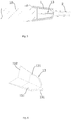
Fig. 5 , this embodiment differs fromEmbodiment 1 in that the rapid heating gun tip for a hot-melt glue gun further comprises acutter 13, thecutter 13 being provided in thetransition tube 1 to axially cut aglue stick 10; thetransition tube 1 and thecutter 13 conduct heat such that thecutter 13 heats thecut glue stick 10. For example, with reference toFig. 6 , thecutter 13 and thetransition tube 1 are separately formed; thecutter 13 is fixedly mounted in thetransition tube 1, e.g., by interference fitting, welding fixation, etc.; thecutter 13 includes three cuttingblades 131 in a radial distribution, wherein the radial outer ends of the three cuttingblades 131 contact with thetransition tube 1 to conduct heat, the three cuttingblades 131 being circumferentially arranged at intervals, with an included angle between twoadjacent cutting blades 131 being 120°; in this way, acylindrical glue stick 10 is cut into three sectored glue sticks with a uniform size. Compared with an entire glue stick, a smaller piece cut from the glue stick is more easily melted under a same heating temperature, which facilitates rapid melting of the glue stick in a short time. Secondly, due to the heat conduction between thetransition tube 1 and thecutter 13, besides heating of thetransition tube 1 with respect to the outer circumferential face of the glue stick, thecutting blade 131 may abut against the cut face of the glue stick to heat, which increases the heated area of the cut portion of the glue stick, such that the cut portion of the glue stick may be melted rapidly in a short time, thereby improving the glue melting efficiency of the rapid heating gun tip and realizing rapid glue jetting. - To better cut the glue stick, a side of each
cutting blade 131 distant from the glue jetting nozzle is thinned to form acutting edge 132. With thrust of the glue stick, thecutting edge 132 may quickly cut the glue stick, thereby decreasing the thrust resistance for the glue stick; besides, local thinning of thecutting blade 131 may reduce heat loss of the cutting blade per se, such that more heat is applied for heating the glue stick. - According to the solution in this embodiment, it may be envisaged that the
cutting blade 131 of the cutter may be provided in two, wherein the two cuttingblades 131 are symmetrically distributed about a central axis of the transition tube, forming a cutter with a "-"-shaped cross section, as shown inFig. 7 . Thecutting blades 131 of the cutter may be provided in four, wherein the fourcutting blades 131 are arranged circumferentially at even intervals, the included angle between twoadjacent cutting blades 131 being 90°, forming a cutter with a "+"-shaped cross section, as shown inFig. 8 . Dependent on actual needs, the number of the cutting blades of the cutter may also be 5, 6, or more. - It may be envisaged from the solution of this embodiment that both of the cutter and the transition tube are made of a metal material and thus may be formed into an integral structure.
- This embodiment discloses a hot-melt glue gun, comprising a rapid heating gun tip for hot-melt glue gun according to any of the embodiment above. Other structures of the hot-melt glue gun are well known to those skilled in the art, which will not be detailed in this embodiment.
- What have been described above are only preferred embodiments of the present disclosure; however, the protection scope of the present disclosure is not limited thereto. A person skilled in the art should understand that the present disclosure includes, but not limited to the contents described in the drawings and the preferred embodiments. Any modifications without departing from the functions and structural principles of the present disclosure will be included within the scope of the claims.
Claims (10)
- A rapid heating gun tip for a hot-melt glue gun, comprising a glue loading sleeve and a glue jetting nozzle, a transition tube being formed between the glue jetting nozzle and the glue loading sleeve; wherein the rapid heating gun tip for a hot-melt glue gun further comprises an electrode sheet and a plurality of heating bodies, the transition tube having a plurality of heat conduction planes, the heat conduction planes being inclined relative to an axial line of the glue loading sleeve, and the electrode sheets tightly press-fitting the heating bodies against outer sides of the heat conduction planes.
- The rapid heating gun tip for a hot-melt glue gun according to claim 1, wherein the heating body is a PTC heating sheet.
- The rapid heating gun tip for a hot-melt glue gun according to claim 1, wherein the rapid heating gun tip for a hot-melt glue gun further comprises a connecting sheet, the transition tube is a conductor, and the transition tube is connected to an external wire via the connecting sheet.
- The rapid heating gun tip for a hot-melt glue gun according to claim 1, wherein the transition tube is an aluminum tube.
- The rapid heating gun tip for a hot-melt glue gun according to any one of claims 1∼4, wherein the rapid heating gun tip for a hot-melt glue gun further comprises a heat insulating sheath in which the electrode sheet, the heating body and the transition tube are accommodated.
- The rapid heating gun tip for a hot-melt glue gun according to any one of claims 1∼4, wherein the rapid heating gun tip for a hot-melt glue gun further comprises a cutter, the cutter being disposed in the transition tube to axially cut a glue stick, the transition tube and the cutter conducting heat to facilitate the cutter to heat the cut glue stick.
- The rapid heating gun tip for a hot-melt glue gun according to claim 6, wherein the cutter comprises at least two cutting blades distributed in a radial mode, radial inner ends of the at least two cutting blades being interconnected and converged at a central axis of the transition tube, and radial outer ends of the at least two cutting blades conducting heat with the transition tube.
- The rapid heating gun tip for a hot-melt glue gun according to claim 7, wherein a side of the cutting blade distant from the glue jetting nozzle is thinned to form a cutting edge.
- The rapid heating gun tip for a hot-melt glue gun according to claim 6, wherein the cutter and the transition tube are integrally formed; or the cutter and the transition tube are separately formed, the cutter being fixedly mounted in the transition tube.
- A hot-melt glue gun, comprising a rapid heating gun tip for a hot-melt glue gun according to any of claims 1∼9.
Applications Claiming Priority (2)
| Application Number | Priority Date | Filing Date | Title |
|---|---|---|---|
| CN201720580859 | 2017-05-23 | ||
| CN201720666043.2U CN206882068U (en) | 2017-05-23 | 2017-06-08 | A kind of thermosol gelgun speed heat pipette tips and thermosol gelgun |
Publications (3)
| Publication Number | Publication Date |
|---|---|
| EP3412366A2 true EP3412366A2 (en) | 2018-12-12 |
| EP3412366A3 EP3412366A3 (en) | 2019-03-20 |
| EP3412366B1 EP3412366B1 (en) | 2022-01-26 |
Family
ID=60305475
Family Applications (1)
| Application Number | Title | Priority Date | Filing Date |
|---|---|---|---|
| EP18176705.4A Active EP3412366B1 (en) | 2017-05-23 | 2018-06-08 | Rapid heating tip for a hot-melt glue gun and a hot-melt glue gun |
Country Status (2)
| Country | Link |
|---|---|
| EP (1) | EP3412366B1 (en) |
| CN (2) | CN107362946A (en) |
Cited By (3)
| Publication number | Priority date | Publication date | Assignee | Title |
|---|---|---|---|---|
| CN110026320A (en) * | 2019-05-21 | 2019-07-19 | 济南希润自动化科技有限公司 | A kind of novel spraying pipette tips |
| CN110293036A (en) * | 2019-07-10 | 2019-10-01 | 浙江茉织华印刷股份有限公司 | A kind of hot melt adhesive glue spreading system |
| CN110496747A (en) * | 2019-08-22 | 2019-11-26 | 宁波耀升工具实业有限公司 | A kind of Rapid hot-melting glue rifle |
Families Citing this family (4)
| Publication number | Priority date | Publication date | Assignee | Title |
|---|---|---|---|---|
| CN107362946A (en) * | 2017-05-23 | 2017-11-21 | 杭州科龙电器工具股份有限公司 | A kind of thermosol gelgun speed heat pipette tips and thermosol gelgun |
| CN108889571A (en) * | 2018-08-30 | 2018-11-27 | 浙江仕善汽车科技股份有限公司 | It is a kind of can uniformly plastic emitting automobile glue rifle |
| CN109848000B (en) * | 2019-01-29 | 2020-11-20 | 大连理工大学 | Novel rotatable hot melt adhesive rifle |
| CN114210515A (en) * | 2021-12-20 | 2022-03-22 | 苏州小易科技有限公司 | Wireless lithium battery mini hot melt adhesive pen |
Citations (3)
| Publication number | Priority date | Publication date | Assignee | Title |
|---|---|---|---|---|
| CN203389820U (en) | 2013-08-19 | 2014-01-15 | 熊欣 | PTC (Positive Temperature Coefficient) hot melt glue gun heater |
| CN205587248U (en) | 2016-02-03 | 2016-09-21 | 卢国峰 | Fast fever type hot melt adhesive rifle |
| CN205731892U (en) | 2016-06-17 | 2016-11-30 | 宁波汉浦工具有限公司 | A kind of electro-heat equipment of thermosol gelgun |
Family Cites Families (6)
| Publication number | Priority date | Publication date | Assignee | Title |
|---|---|---|---|---|
| FR2759925B1 (en) * | 1997-02-21 | 1999-05-14 | Sofragraf Ind | APPLICATOR OF HEAT-MELT ADHESIVE AND ADHESIVE STICK DESIGNED TO SUPPLY SUCH AN APPLICATOR |
| TW493537U (en) * | 2001-06-15 | 2002-07-01 | Gene Yu Ent Ltd | Structure for heating nozzle of thermal melting gun |
| DE102014015211A1 (en) * | 2014-10-16 | 2016-04-21 | Bühnen GmbH & Co. KG | Hot glue gun |
| CN204503468U (en) * | 2015-03-10 | 2015-07-29 | 宁波耀升工具实业有限公司 | A kind of thermosol gelgun |
| CN106076745B (en) * | 2016-06-17 | 2018-11-09 | 宁波汉浦工具有限公司 | A kind of Rapid hot-melting glue rifle |
| CN107362946A (en) * | 2017-05-23 | 2017-11-21 | 杭州科龙电器工具股份有限公司 | A kind of thermosol gelgun speed heat pipette tips and thermosol gelgun |
-
2017
- 2017-06-08 CN CN201710425814.3A patent/CN107362946A/en active Pending
- 2017-06-08 CN CN201720666043.2U patent/CN206882068U/en active Active
-
2018
- 2018-06-08 EP EP18176705.4A patent/EP3412366B1/en active Active
Patent Citations (3)
| Publication number | Priority date | Publication date | Assignee | Title |
|---|---|---|---|---|
| CN203389820U (en) | 2013-08-19 | 2014-01-15 | 熊欣 | PTC (Positive Temperature Coefficient) hot melt glue gun heater |
| CN205587248U (en) | 2016-02-03 | 2016-09-21 | 卢国峰 | Fast fever type hot melt adhesive rifle |
| CN205731892U (en) | 2016-06-17 | 2016-11-30 | 宁波汉浦工具有限公司 | A kind of electro-heat equipment of thermosol gelgun |
Cited By (4)
| Publication number | Priority date | Publication date | Assignee | Title |
|---|---|---|---|---|
| CN110026320A (en) * | 2019-05-21 | 2019-07-19 | 济南希润自动化科技有限公司 | A kind of novel spraying pipette tips |
| CN110026320B (en) * | 2019-05-21 | 2024-01-26 | 济南希润自动化科技有限公司 | Novel gun head for spraying |
| CN110293036A (en) * | 2019-07-10 | 2019-10-01 | 浙江茉织华印刷股份有限公司 | A kind of hot melt adhesive glue spreading system |
| CN110496747A (en) * | 2019-08-22 | 2019-11-26 | 宁波耀升工具实业有限公司 | A kind of Rapid hot-melting glue rifle |
Also Published As
| Publication number | Publication date |
|---|---|
| EP3412366B1 (en) | 2022-01-26 |
| CN107362946A (en) | 2017-11-21 |
| EP3412366A3 (en) | 2019-03-20 |
| CN206882068U (en) | 2018-01-16 |
Similar Documents
| Publication | Publication Date | Title |
|---|---|---|
| EP3412366B1 (en) | Rapid heating tip for a hot-melt glue gun and a hot-melt glue gun | |
| CN100360270C (en) | Resistance welding head for conjoined electrode and preparation method thereof | |
| CN110770958B (en) | Battery pack device, battery pack of hand-held power tool, and laser welding method | |
| US20090045174A1 (en) | Device for exchanging a nozzle of a vapor plasma burner and nozzle and guard ring | |
| US11273509B2 (en) | Heating tool | |
| CN109156902B (en) | Heating element and be equipped with this heating element's electron smoking set | |
| US10189104B2 (en) | Rotatable electric heating tool | |
| CN110839965A (en) | Electron cigarette heating element | |
| CN216147242U (en) | Aerosol generating device and heating assembly thereof | |
| CN112077424A (en) | Welding method of cutter | |
| JP2020123725A (en) | Electric terminal | |
| CN204221183U (en) | Handle prepressing type thermocouple wire quick welding device | |
| US11420281B2 (en) | Electric heating device | |
| EP4218445A1 (en) | Heating assembly and aerosol-forming device | |
| US9844831B2 (en) | Resistance spot welding system and method | |
| CN109530848B (en) | Quick response tungsten-rhenium thermocouple welding method | |
| WO2021260201A3 (en) | Apparatus for heating aerosolisable material | |
| CN211458862U (en) | Electron cigarette heating element | |
| CN109175583A (en) | A kind of electric iron device | |
| US2415778A (en) | Electrode holder | |
| CN217523962U (en) | Aerosol generator and resistance heater thereof | |
| CN210862968U (en) | High-temperature film temperature sensor | |
| CN215791840U (en) | Hot melt riveting head | |
| CN216752121U (en) | PTC heating element for hot melt adhesive gun | |
| JP4314564B2 (en) | How to connect electronic components and lead wires |
Legal Events
| Date | Code | Title | Description |
|---|---|---|---|
| PUAI | Public reference made under article 153(3) epc to a published international application that has entered the european phase |
Free format text: ORIGINAL CODE: 0009012 |
|
| STAA | Information on the status of an ep patent application or granted ep patent |
Free format text: STATUS: THE APPLICATION HAS BEEN PUBLISHED |
|
| AK | Designated contracting states |
Kind code of ref document: A2 Designated state(s): AL AT BE BG CH CY CZ DE DK EE ES FI FR GB GR HR HU IE IS IT LI LT LU LV MC MK MT NL NO PL PT RO RS SE SI SK SM TR |
|
| AX | Request for extension of the european patent |
Extension state: BA ME |
|
| PUAL | Search report despatched |
Free format text: ORIGINAL CODE: 0009013 |
|
| AK | Designated contracting states |
Kind code of ref document: A3 Designated state(s): AL AT BE BG CH CY CZ DE DK EE ES FI FR GB GR HR HU IE IS IT LI LT LU LV MC MK MT NL NO PL PT RO RS SE SI SK SM TR |
|
| AX | Request for extension of the european patent |
Extension state: BA ME |
|
| RIC1 | Information provided on ipc code assigned before grant |
Ipc: B05C 17/005 20060101AFI20190208BHEP |
|
| STAA | Information on the status of an ep patent application or granted ep patent |
Free format text: STATUS: REQUEST FOR EXAMINATION WAS MADE |
|
| 17P | Request for examination filed |
Effective date: 20190920 |
|
| RBV | Designated contracting states (corrected) |
Designated state(s): AL AT BE BG CH CY CZ DE DK EE ES FI FR GB GR HR HU IE IS IT LI LT LU LV MC MK MT NL NO PL PT RO RS SE SI SK SM TR |
|
| GRAP | Despatch of communication of intention to grant a patent |
Free format text: ORIGINAL CODE: EPIDOSNIGR1 |
|
| STAA | Information on the status of an ep patent application or granted ep patent |
Free format text: STATUS: GRANT OF PATENT IS INTENDED |
|
| RIC1 | Information provided on ipc code assigned before grant |
Ipc: B05C 17/005 20060101AFI20201110BHEP |
|
| INTG | Intention to grant announced |
Effective date: 20201216 |
|
| GRAS | Grant fee paid |
Free format text: ORIGINAL CODE: EPIDOSNIGR3 |
|
| STAA | Information on the status of an ep patent application or granted ep patent |
Free format text: STATUS: GRANT OF PATENT IS INTENDED |
|
| RAP3 | Party data changed (applicant data changed or rights of an application transferred) |
Owner name: HANGZHOU KELONG ELECTRICAL APPLIANCE TOOLS CO. LTD |
|
| GRAA | (expected) grant |
Free format text: ORIGINAL CODE: 0009210 |
|
| STAA | Information on the status of an ep patent application or granted ep patent |
Free format text: STATUS: THE PATENT HAS BEEN GRANTED |
|
| AK | Designated contracting states |
Kind code of ref document: B1 Designated state(s): AL AT BE BG CH CY CZ DE DK EE ES FI FR GB GR HR HU IE IS IT LI LT LU LV MC MK MT NL NO PL PT RO RS SE SI SK SM TR |
|
| REG | Reference to a national code |
Ref country code: GB Ref legal event code: FG4D |
|
| REG | Reference to a national code |
Ref country code: CH Ref legal event code: EP |
|
| REG | Reference to a national code |
Ref country code: AT Ref legal event code: REF Ref document number: 1464839 Country of ref document: AT Kind code of ref document: T Effective date: 20220215 |
|
| REG | Reference to a national code |
Ref country code: IE Ref legal event code: FG4D |
|
| REG | Reference to a national code |
Ref country code: DE Ref legal event code: R096 Ref document number: 602018029959 Country of ref document: DE |
|
| REG | Reference to a national code |
Ref country code: LT Ref legal event code: MG9D |
|
| REG | Reference to a national code |
Ref country code: NL Ref legal event code: MP Effective date: 20220126 |
|
| REG | Reference to a national code |
Ref country code: AT Ref legal event code: MK05 Ref document number: 1464839 Country of ref document: AT Kind code of ref document: T Effective date: 20220126 |
|
| PG25 | Lapsed in a contracting state [announced via postgrant information from national office to epo] |
Ref country code: NL Free format text: LAPSE BECAUSE OF FAILURE TO SUBMIT A TRANSLATION OF THE DESCRIPTION OR TO PAY THE FEE WITHIN THE PRESCRIBED TIME-LIMIT Effective date: 20220126 |
|
| PG25 | Lapsed in a contracting state [announced via postgrant information from national office to epo] |
Ref country code: SE Free format text: LAPSE BECAUSE OF FAILURE TO SUBMIT A TRANSLATION OF THE DESCRIPTION OR TO PAY THE FEE WITHIN THE PRESCRIBED TIME-LIMIT Effective date: 20220126 Ref country code: RS Free format text: LAPSE BECAUSE OF FAILURE TO SUBMIT A TRANSLATION OF THE DESCRIPTION OR TO PAY THE FEE WITHIN THE PRESCRIBED TIME-LIMIT Effective date: 20220126 Ref country code: PT Free format text: LAPSE BECAUSE OF FAILURE TO SUBMIT A TRANSLATION OF THE DESCRIPTION OR TO PAY THE FEE WITHIN THE PRESCRIBED TIME-LIMIT Effective date: 20220526 Ref country code: NO Free format text: LAPSE BECAUSE OF FAILURE TO SUBMIT A TRANSLATION OF THE DESCRIPTION OR TO PAY THE FEE WITHIN THE PRESCRIBED TIME-LIMIT Effective date: 20220426 Ref country code: LT Free format text: LAPSE BECAUSE OF FAILURE TO SUBMIT A TRANSLATION OF THE DESCRIPTION OR TO PAY THE FEE WITHIN THE PRESCRIBED TIME-LIMIT Effective date: 20220126 Ref country code: HR Free format text: LAPSE BECAUSE OF FAILURE TO SUBMIT A TRANSLATION OF THE DESCRIPTION OR TO PAY THE FEE WITHIN THE PRESCRIBED TIME-LIMIT Effective date: 20220126 Ref country code: ES Free format text: LAPSE BECAUSE OF FAILURE TO SUBMIT A TRANSLATION OF THE DESCRIPTION OR TO PAY THE FEE WITHIN THE PRESCRIBED TIME-LIMIT Effective date: 20220126 Ref country code: BG Free format text: LAPSE BECAUSE OF FAILURE TO SUBMIT A TRANSLATION OF THE DESCRIPTION OR TO PAY THE FEE WITHIN THE PRESCRIBED TIME-LIMIT Effective date: 20220426 |
|
| PG25 | Lapsed in a contracting state [announced via postgrant information from national office to epo] |
Ref country code: PL Free format text: LAPSE BECAUSE OF FAILURE TO SUBMIT A TRANSLATION OF THE DESCRIPTION OR TO PAY THE FEE WITHIN THE PRESCRIBED TIME-LIMIT Effective date: 20220126 Ref country code: LV Free format text: LAPSE BECAUSE OF FAILURE TO SUBMIT A TRANSLATION OF THE DESCRIPTION OR TO PAY THE FEE WITHIN THE PRESCRIBED TIME-LIMIT Effective date: 20220126 Ref country code: GR Free format text: LAPSE BECAUSE OF FAILURE TO SUBMIT A TRANSLATION OF THE DESCRIPTION OR TO PAY THE FEE WITHIN THE PRESCRIBED TIME-LIMIT Effective date: 20220427 Ref country code: FI Free format text: LAPSE BECAUSE OF FAILURE TO SUBMIT A TRANSLATION OF THE DESCRIPTION OR TO PAY THE FEE WITHIN THE PRESCRIBED TIME-LIMIT Effective date: 20220126 Ref country code: AT Free format text: LAPSE BECAUSE OF FAILURE TO SUBMIT A TRANSLATION OF THE DESCRIPTION OR TO PAY THE FEE WITHIN THE PRESCRIBED TIME-LIMIT Effective date: 20220126 |
|
| PG25 | Lapsed in a contracting state [announced via postgrant information from national office to epo] |
Ref country code: IS Free format text: LAPSE BECAUSE OF FAILURE TO SUBMIT A TRANSLATION OF THE DESCRIPTION OR TO PAY THE FEE WITHIN THE PRESCRIBED TIME-LIMIT Effective date: 20220526 |
|
| REG | Reference to a national code |
Ref country code: DE Ref legal event code: R097 Ref document number: 602018029959 Country of ref document: DE |
|
| PG25 | Lapsed in a contracting state [announced via postgrant information from national office to epo] |
Ref country code: SM Free format text: LAPSE BECAUSE OF FAILURE TO SUBMIT A TRANSLATION OF THE DESCRIPTION OR TO PAY THE FEE WITHIN THE PRESCRIBED TIME-LIMIT Effective date: 20220126 Ref country code: SK Free format text: LAPSE BECAUSE OF FAILURE TO SUBMIT A TRANSLATION OF THE DESCRIPTION OR TO PAY THE FEE WITHIN THE PRESCRIBED TIME-LIMIT Effective date: 20220126 Ref country code: RO Free format text: LAPSE BECAUSE OF FAILURE TO SUBMIT A TRANSLATION OF THE DESCRIPTION OR TO PAY THE FEE WITHIN THE PRESCRIBED TIME-LIMIT Effective date: 20220126 Ref country code: EE Free format text: LAPSE BECAUSE OF FAILURE TO SUBMIT A TRANSLATION OF THE DESCRIPTION OR TO PAY THE FEE WITHIN THE PRESCRIBED TIME-LIMIT Effective date: 20220126 Ref country code: DK Free format text: LAPSE BECAUSE OF FAILURE TO SUBMIT A TRANSLATION OF THE DESCRIPTION OR TO PAY THE FEE WITHIN THE PRESCRIBED TIME-LIMIT Effective date: 20220126 Ref country code: CZ Free format text: LAPSE BECAUSE OF FAILURE TO SUBMIT A TRANSLATION OF THE DESCRIPTION OR TO PAY THE FEE WITHIN THE PRESCRIBED TIME-LIMIT Effective date: 20220126 |
|
| PG25 | Lapsed in a contracting state [announced via postgrant information from national office to epo] |
Ref country code: AL Free format text: LAPSE BECAUSE OF FAILURE TO SUBMIT A TRANSLATION OF THE DESCRIPTION OR TO PAY THE FEE WITHIN THE PRESCRIBED TIME-LIMIT Effective date: 20220126 |
|
| PLBE | No opposition filed within time limit |
Free format text: ORIGINAL CODE: 0009261 |
|
| STAA | Information on the status of an ep patent application or granted ep patent |
Free format text: STATUS: NO OPPOSITION FILED WITHIN TIME LIMIT |
|
| 26N | No opposition filed |
Effective date: 20221027 |
|
| PG25 | Lapsed in a contracting state [announced via postgrant information from national office to epo] |
Ref country code: MC Free format text: LAPSE BECAUSE OF FAILURE TO SUBMIT A TRANSLATION OF THE DESCRIPTION OR TO PAY THE FEE WITHIN THE PRESCRIBED TIME-LIMIT Effective date: 20220126 |
|
| REG | Reference to a national code |
Ref country code: CH Ref legal event code: PL |
|
| REG | Reference to a national code |
Ref country code: BE Ref legal event code: MM Effective date: 20220630 |
|
| PG25 | Lapsed in a contracting state [announced via postgrant information from national office to epo] |
Ref country code: SI Free format text: LAPSE BECAUSE OF FAILURE TO SUBMIT A TRANSLATION OF THE DESCRIPTION OR TO PAY THE FEE WITHIN THE PRESCRIBED TIME-LIMIT Effective date: 20220126 |
|
| PG25 | Lapsed in a contracting state [announced via postgrant information from national office to epo] |
Ref country code: LU Free format text: LAPSE BECAUSE OF NON-PAYMENT OF DUE FEES Effective date: 20220608 Ref country code: LI Free format text: LAPSE BECAUSE OF NON-PAYMENT OF DUE FEES Effective date: 20220630 Ref country code: IE Free format text: LAPSE BECAUSE OF NON-PAYMENT OF DUE FEES Effective date: 20220608 Ref country code: CH Free format text: LAPSE BECAUSE OF NON-PAYMENT OF DUE FEES Effective date: 20220630 |
|
| PG25 | Lapsed in a contracting state [announced via postgrant information from national office to epo] |
Ref country code: BE Free format text: LAPSE BECAUSE OF NON-PAYMENT OF DUE FEES Effective date: 20220630 |
|
| PGFP | Annual fee paid to national office [announced via postgrant information from national office to epo] |
Ref country code: IT Payment date: 20230609 Year of fee payment: 6 Ref country code: FR Payment date: 20230630 Year of fee payment: 6 Ref country code: DE Payment date: 20230613 Year of fee payment: 6 |
|
| PGFP | Annual fee paid to national office [announced via postgrant information from national office to epo] |
Ref country code: GB Payment date: 20230620 Year of fee payment: 6 |
|
| PG25 | Lapsed in a contracting state [announced via postgrant information from national office to epo] |
Ref country code: HU Free format text: LAPSE BECAUSE OF FAILURE TO SUBMIT A TRANSLATION OF THE DESCRIPTION OR TO PAY THE FEE WITHIN THE PRESCRIBED TIME-LIMIT; INVALID AB INITIO Effective date: 20180608 |
|
| PG25 | Lapsed in a contracting state [announced via postgrant information from national office to epo] |
Ref country code: MK Free format text: LAPSE BECAUSE OF FAILURE TO SUBMIT A TRANSLATION OF THE DESCRIPTION OR TO PAY THE FEE WITHIN THE PRESCRIBED TIME-LIMIT Effective date: 20220126 Ref country code: CY Free format text: LAPSE BECAUSE OF FAILURE TO SUBMIT A TRANSLATION OF THE DESCRIPTION OR TO PAY THE FEE WITHIN THE PRESCRIBED TIME-LIMIT Effective date: 20220126 |