EP3411613B1 - Control valve, in particularl for use in cooling paths - Google Patents
Control valve, in particularl for use in cooling paths Download PDFInfo
- Publication number
- EP3411613B1 EP3411613B1 EP17702551.7A EP17702551A EP3411613B1 EP 3411613 B1 EP3411613 B1 EP 3411613B1 EP 17702551 A EP17702551 A EP 17702551A EP 3411613 B1 EP3411613 B1 EP 3411613B1
- Authority
- EP
- European Patent Office
- Prior art keywords
- control valve
- throttle body
- actuator
- membrane
- linear motor
- Prior art date
- Legal status (The legal status is an assumption and is not a legal conclusion. Google has not performed a legal analysis and makes no representation as to the accuracy of the status listed.)
- Active
Links
- 238000001816 cooling Methods 0.000 title claims description 12
- 239000012528 membrane Substances 0.000 claims description 14
- 238000005096 rolling process Methods 0.000 claims description 12
- 230000001360 synchronised effect Effects 0.000 claims description 6
- 239000002826 coolant Substances 0.000 claims description 3
- 239000007788 liquid Substances 0.000 claims description 2
- 239000000498 cooling water Substances 0.000 description 7
- 230000004044 response Effects 0.000 description 6
- 238000000034 method Methods 0.000 description 5
- 230000008569 process Effects 0.000 description 4
- 230000035484 reaction time Effects 0.000 description 4
- XLYOFNOQVPJJNP-UHFFFAOYSA-N water Substances O XLYOFNOQVPJJNP-UHFFFAOYSA-N 0.000 description 4
- 229910045601 alloy Inorganic materials 0.000 description 3
- 239000000956 alloy Substances 0.000 description 3
- 239000000463 material Substances 0.000 description 3
- 238000003303 reheating Methods 0.000 description 3
- 230000000930 thermomechanical effect Effects 0.000 description 3
- 229910000831 Steel Inorganic materials 0.000 description 2
- 230000008878 coupling Effects 0.000 description 2
- 238000010168 coupling process Methods 0.000 description 2
- 238000005859 coupling reaction Methods 0.000 description 2
- 238000010438 heat treatment Methods 0.000 description 2
- 230000005291 magnetic effect Effects 0.000 description 2
- 229910000734 martensite Inorganic materials 0.000 description 2
- 239000010959 steel Substances 0.000 description 2
- 229910001369 Brass Inorganic materials 0.000 description 1
- 229910001208 Crucible steel Inorganic materials 0.000 description 1
- 229910001060 Gray iron Inorganic materials 0.000 description 1
- 229910000746 Structural steel Inorganic materials 0.000 description 1
- 230000005540 biological transmission Effects 0.000 description 1
- 239000010951 brass Substances 0.000 description 1
- 230000008859 change Effects 0.000 description 1
- 238000006243 chemical reaction Methods 0.000 description 1
- 239000007795 chemical reaction product Substances 0.000 description 1
- 230000000694 effects Effects 0.000 description 1
- 210000003746 feather Anatomy 0.000 description 1
- 239000003302 ferromagnetic material Substances 0.000 description 1
- 230000004907 flux Effects 0.000 description 1
- 238000005098 hot rolling Methods 0.000 description 1
- 230000005415 magnetization Effects 0.000 description 1
- 238000004519 manufacturing process Methods 0.000 description 1
- 239000004033 plastic Substances 0.000 description 1
- 239000000047 product Substances 0.000 description 1
- 230000009467 reduction Effects 0.000 description 1
- 239000010935 stainless steel Substances 0.000 description 1
- 229910001220 stainless steel Inorganic materials 0.000 description 1
- 230000003068 static effect Effects 0.000 description 1
- 230000007704 transition Effects 0.000 description 1
- 238000003466 welding Methods 0.000 description 1
- 238000004804 winding Methods 0.000 description 1
Images


Classifications
-
- F—MECHANICAL ENGINEERING; LIGHTING; HEATING; WEAPONS; BLASTING
- F16—ENGINEERING ELEMENTS AND UNITS; GENERAL MEASURES FOR PRODUCING AND MAINTAINING EFFECTIVE FUNCTIONING OF MACHINES OR INSTALLATIONS; THERMAL INSULATION IN GENERAL
- F16K—VALVES; TAPS; COCKS; ACTUATING-FLOATS; DEVICES FOR VENTING OR AERATING
- F16K31/00—Actuating devices; Operating means; Releasing devices
- F16K31/02—Actuating devices; Operating means; Releasing devices electric; magnetic
- F16K31/04—Actuating devices; Operating means; Releasing devices electric; magnetic using a motor
- F16K31/046—Actuating devices; Operating means; Releasing devices electric; magnetic using a motor with electric means, e.g. electric switches, to control the motor or to control a clutch between the valve and the motor
-
- F—MECHANICAL ENGINEERING; LIGHTING; HEATING; WEAPONS; BLASTING
- F16—ENGINEERING ELEMENTS AND UNITS; GENERAL MEASURES FOR PRODUCING AND MAINTAINING EFFECTIVE FUNCTIONING OF MACHINES OR INSTALLATIONS; THERMAL INSULATION IN GENERAL
- F16K—VALVES; TAPS; COCKS; ACTUATING-FLOATS; DEVICES FOR VENTING OR AERATING
- F16K31/00—Actuating devices; Operating means; Releasing devices
- F16K31/02—Actuating devices; Operating means; Releasing devices electric; magnetic
- F16K31/06—Actuating devices; Operating means; Releasing devices electric; magnetic using a magnet, e.g. diaphragm valves, cutting off by means of a liquid
- F16K31/0644—One-way valve
- F16K31/0655—Lift valves
- F16K31/0658—Armature and valve member being one single element
-
- F—MECHANICAL ENGINEERING; LIGHTING; HEATING; WEAPONS; BLASTING
- F16—ENGINEERING ELEMENTS AND UNITS; GENERAL MEASURES FOR PRODUCING AND MAINTAINING EFFECTIVE FUNCTIONING OF MACHINES OR INSTALLATIONS; THERMAL INSULATION IN GENERAL
- F16K—VALVES; TAPS; COCKS; ACTUATING-FLOATS; DEVICES FOR VENTING OR AERATING
- F16K31/00—Actuating devices; Operating means; Releasing devices
- F16K31/02—Actuating devices; Operating means; Releasing devices electric; magnetic
- F16K31/04—Actuating devices; Operating means; Releasing devices electric; magnetic using a motor
-
- F—MECHANICAL ENGINEERING; LIGHTING; HEATING; WEAPONS; BLASTING
- F16—ENGINEERING ELEMENTS AND UNITS; GENERAL MEASURES FOR PRODUCING AND MAINTAINING EFFECTIVE FUNCTIONING OF MACHINES OR INSTALLATIONS; THERMAL INSULATION IN GENERAL
- F16K—VALVES; TAPS; COCKS; ACTUATING-FLOATS; DEVICES FOR VENTING OR AERATING
- F16K31/00—Actuating devices; Operating means; Releasing devices
- F16K31/02—Actuating devices; Operating means; Releasing devices electric; magnetic
- F16K31/06—Actuating devices; Operating means; Releasing devices electric; magnetic using a magnet, e.g. diaphragm valves, cutting off by means of a liquid
- F16K31/08—Actuating devices; Operating means; Releasing devices electric; magnetic using a magnet, e.g. diaphragm valves, cutting off by means of a liquid using a permanent magnet
- F16K31/082—Actuating devices; Operating means; Releasing devices electric; magnetic using a magnet, e.g. diaphragm valves, cutting off by means of a liquid using a permanent magnet using a electromagnet and a permanent magnet
-
- F—MECHANICAL ENGINEERING; LIGHTING; HEATING; WEAPONS; BLASTING
- F16—ENGINEERING ELEMENTS AND UNITS; GENERAL MEASURES FOR PRODUCING AND MAINTAINING EFFECTIVE FUNCTIONING OF MACHINES OR INSTALLATIONS; THERMAL INSULATION IN GENERAL
- F16K—VALVES; TAPS; COCKS; ACTUATING-FLOATS; DEVICES FOR VENTING OR AERATING
- F16K31/00—Actuating devices; Operating means; Releasing devices
- F16K31/12—Actuating devices; Operating means; Releasing devices actuated by fluid
- F16K31/126—Actuating devices; Operating means; Releasing devices actuated by fluid the fluid acting on a diaphragm, bellows, or the like
- F16K31/1262—Actuating devices; Operating means; Releasing devices actuated by fluid the fluid acting on a diaphragm, bellows, or the like one side of the diaphragm being spring loaded
-
- H—ELECTRICITY
- H01—ELECTRIC ELEMENTS
- H01F—MAGNETS; INDUCTANCES; TRANSFORMERS; SELECTION OF MATERIALS FOR THEIR MAGNETIC PROPERTIES
- H01F7/00—Magnets
- H01F7/06—Electromagnets; Actuators including electromagnets
- H01F7/08—Electromagnets; Actuators including electromagnets with armatures
- H01F7/16—Rectilinearly-movable armatures
- H01F7/1607—Armatures entering the winding
- H01F7/1615—Armatures or stationary parts of magnetic circuit having permanent magnet
-
- B—PERFORMING OPERATIONS; TRANSPORTING
- B21—MECHANICAL METAL-WORKING WITHOUT ESSENTIALLY REMOVING MATERIAL; PUNCHING METAL
- B21B—ROLLING OF METAL
- B21B45/00—Devices for surface or other treatment of work, specially combined with or arranged in, or specially adapted for use in connection with, metal-rolling mills
- B21B45/02—Devices for surface or other treatment of work, specially combined with or arranged in, or specially adapted for use in connection with, metal-rolling mills for lubricating, cooling, or cleaning
- B21B45/0203—Cooling
Definitions
- the invention relates to a control valve for adjusting the flow cross section in a pipeline, in particular for the highly dynamic control of the amount of cooling water in cooling sections in rolling mills.
- a control valve is an auxiliary device that regulates the flow in a process system.
- the Tempcore process is mainly used in the manufacture of structural steel.
- the finished rolled product is heat-treated in front of the cooling bed (steel bars) or the winding layer (wire) from the rolling heat.
- the rolling stock leaves the last rolling stand at a temperature of 950-1050 ° C.
- the outer layer is cooled by water under high pressure (5 ⁇ 16bar) to temperatures ⁇ 400 ° C. This creates a martensitic structure.
- the martensitic outer layer is reheated (tempered) and on the other hand the core is cooled, which creates a ferritic-pearlitic structure.
- the Tempcore process the required mechanical properties of the end product can be reduced while the surcharge of Alloy elements can be achieved.
- the exact temperature control determines the savings potential of alloy elements.
- thermomechanical rolling the rolling stock is cooled to a defined temperature before the last forming steps. This leads to a fine-grained structure, which at the same time has good toughness with high strength and offers cold formability.
- Different types are used: Thermomechanical rolling achieves mechanical properties that would otherwise only be achieved by adding alloy elements can be. Precise temperature control is a prerequisite for the use of thermomechanical rolling processes.
- the heating of the continuous cast billets in the reheating furnace in front of the hot rolling mill is never completely uniform over the length of the Stick.
- the reheating furnace directly behind the continuous caster is used to warm up the cooled continuous billets.
- water-cooled rails are required on which the billets rest during the heating. Shading occurs in the area of the rails, which is manifested by a temperature profile along the length of the billets. In order to avoid temperature deviations over the length of the billets, highly dynamic control of the cooling water is required.
- Actuators with pneumatic actuation respond in a short to medium reaction time.
- the problem is that the transition from static to sliding friction leads to a stick-slip effect, which leads to non-reproducible response behavior and thus inconsistent response times.
- Pneumatic drives are therefore unsuitable for high-precision, dynamic control processes.
- Actuators with an electric drive are based on a self-locking motor-gear unit with short reaction times, high positioning accuracy, but with low positioning speeds.
- the GB 2 460 336 A discloses an underwater wellhead termination member having multiple shut-off valves for controlling the flow of liquids into and out of a wellbore.
- the closure element In order to move the closure element of the shut-off valve back and forth from the open to a closed position, the closure element is connected to a linear motor via a valve stem.
- the WO 2009/048995 A1 discloses a shut-off two-way valve comprising a valve housing, a cylindrical closure element which is movable to and fro in the valve housing and which is connected to a linear actuator via a rod.
- the linear actuator connected to the closure element comprises a plurality of annular stator disks, a plurality of annular stator coils which are arranged between the stator disks, a plurality of teeth which form a cylindrical opening, a slide with a plurality of teeth which is movably arranged in the cylindrical opening and the surfaces of which have a cylindrical outer jacket of the Form slide, wherein the slide is moved by the magnetic flux of the stator coils, which is caused by a current flow in the coils.
- the principle of operation of the linear actuator is based on a reduction in the magnetic resistance between the inner teeth of the cylindrical opening on the one hand and the outer teeth and the slide on the other.
- the US 2008/191825 A1 discloses a linear actuator for actuating an engine valve.
- the linear actuator comprises an upper stationary permanent magnet and a lower magnet aligned with the upper permanent magnet in the axial direction, the upper and lower permanent magnets having different magnetizations, an upper coil which is arranged within the upper magnet and a lower coil which is arranged within the lower magnet and a displaceably arranged part made of ferromagnetic material, the displaceable part moving due to the forces which are caused by a current flow in the stationary coils.
- the DE 24 42 587 B1 discloses a control valve for adjusting the flow cross-section in at least one pipeline comprising a cylindrical throttle body, a valve seat and a diaphragm actuator for changing the position of the cylindrical throttle body.
- the diaphragm actuator has an actuating rod which is guided in a coaxial hollow cylindrical fastening projection which projects like a pin on the housing of the diaphragm actuator.
- the housing of the diaphragm actuator is supported against the valve housing by means of a two-part rigid stand.
- the rigid stand consists of two detachably connected parts.
- the actuating rod of the diaphragm actuator is coupled to the valve spindle by a releasable positive coupling, so that the actuating force exerted on the actuating rod of the diaphragm actuator is transmitted to the valve rod.
- the two-part rigid stand and the coupling serve the purpose of enabling simple and reliable assembly and disassembly of the diaphragm actuator.
- the US 6,329,728 B1 discloses a synchronous linear motor with a coil unit fixedly arranged on the inner wall of a tubular housing and a rod-shaped actuating member with a permanent magnet unit. There is a sensor inside the housing of the synchronous linear motor arranged to determine the relative position between the movable member and the stator in the axial direction.
- the object of the invention is to propose a control valve for adjusting the flow cross section in a pipeline, in particular for the highly dynamic control of the amount of cooling water in cooling sections in rolling mills, which has a reproducible response behavior, short reaction times and high positioning accuracy.
- the control valve can be designed as a single-seat control valve or as a multi-seat control valve, in particular a double-seat control valve.
- the actuating forces can be reduced by using multi-seat control valves.
- control valve can be designed as a multi-way control valve to mix or divide material flows.
- each throttle body determines the flow characteristic. With the variable flow, you can regulate the pressure, the temperature or the flow of the medium itself.
- Gray cast iron, brass, cast steel, stainless steel or plastic are used as materials for control valves.
- the control valve can be installed in the pipeline or the pipeline network in various ways. For example, welding, clamping or, preferably, connection via flanges can be considered.
- the linear motor moves the throttle body or bodies of the control valve in a guided translation movement.
- the linear motor as a direct drive makes it possible to immediately generate a translatory movement with different forces and / or speeds.
- the linear motor has a short response time with high positioning speed and high positioning accuracy, and the response time is also reproducible.
- a control valve with such an actuator is ideally suited for the highly dynamic control of the amount of cooling water in cooling sections in rolling mills.
- the linear motor comprises a current-carrying primary part and a reaction or secondary part; it is designed as a synchronous linear motor.
- the permanent magnets of the synchronous linear motor interact with a stationary primary part. In particular, no moving lines are required for the energy supply of the synchronous linear motor.
- the permanent magnet unit is arranged directly on an actuator for each throttle body.
- the positioning accuracy of the actuator can be increased further, since no transmission elements with play are provided between the actuator and the throttle body which is directly connected to the actuating member.
- the permanent magnet unit is designed as an integral part of the rod-shaped actuator.
- the rod-shaped actuator performs a translational movement as part of the linear drive in order to move the throttle body back and forth.
- a position control for the linear motor is provided. Despite the low inertial mass of the linear motor, the position control contributes to the desired high positioning accuracy even with pressure and volume fluctuations of the controlled cooling medium.
- the actuator additionally comprises a diaphragm drive with a diaphragm which can be acted upon with a pressure medium at least on a first side of the diaphragm.
- the linear motor takes over the very high peak force for opening the control valve, which is then at least partially taken over by the diaphragm drive. If the first side of the diaphragm drive is acted upon by a pressure medium and the second side of the diaphragm by at least one spring, the control valve can be automatically closed or opened in the event of a power failure of the linear motor.
- the pneumatic drive can be designed with a membrane that can be individually loaded with pressure medium on both sides.
- the additional membrane drive is advantageously integrated into the actuator in that the membrane is attached to the upper end of the rod-shaped actuating member.
- the control valve (1) comprises a valve housing (2) with an inlet and outlet (2a, 2b), a throttle body (3) and a valve seat (4).
- the valve stem (4a) connected to the throttle body (3) is coupled to a rod-shaped actuating member (5) outside the valve housing (2).
- the actuating member (5) is guided in a drive housing (6) so that it can be moved back and forth in a translatory manner in the vertical direction in order to move the throttle body (3) coupled to the actuating member (5) between an in Figure 1 shown, closed position and an open position to move back and forth.
- the throttle body (3) which tapers downward, is designed in such a way that in the closed position it Flow between the throttle body (3) and the valve seat (4) is prevented.
- an annular flow cross section results between the valve seat (4) and the throttle body (3), which increases due to the cross-sectional shape of the throttle body during the movement into the fully open position.
- the actuator (7, 8) comprises a linear motor (7) and a diaphragm drive (8).
- the linear motor (7) is formed by a coil unit (7a) arranged in the drive housing (6) and a permanent magnet unit (7b).
- the permanent magnet unit (7b) is designed as an integral part, namely as part of the rod-shaped actuating member (5).
- the diaphragm drive (8) placed on the drive housing (6) and fastened there comprises a diaphragm (8a) which is clamped between the housing halves (8b, 8c) of the diaphragm housing (8d).
- the upper end of the rod-shaped actuating member (5) is guided into the membrane housing via a gas-tight bushing (8e) and fastened in the center of the membrane (8a).
- a pressure medium can be applied to the membrane (8a) from the underside.
- the top of the membrane is loaded by springs (8f), which are supported on the upper half of the housing (8b).
- the springs (8f) cause the diaphragm (8a) to be loaded in the closing direction of the control valve (1) if there is a pressure drop in the lower chamber of the diaphragm drive (8).
- Figures 2a to 2d show different embodiments of valve housings, which are intended for three-way control valves.
- the embodiments according to Figures 2a and 2b each have a throttle body that interacts with two valve seats.
- the embodiments according to Figures 2c and 2d have two throttle bodies, each of which cooperate with a valve seat.
- control valves in the closed position only significantly reduce the flow, but do not prevent it.
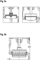
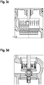
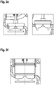
- Figure 3 shows different embodiments of the throttle body, which have an influence on the flow characteristic.
- Figure 3a shows one as a parabolic cone
- Figure 3b one as a hole cone
- Figure 3c one as a perforated cone with a perforated basket
- Figure 3d one as a hole cone for a control valve in three-way design
- Figure 3e one as a lantern cone
- Figure 3f a throttle body designed as a lantern cone with pressure relief.
- No. description 1 Control valve Second valve housing 2a. inlet 2 B. outlet Third throttle body 4th valve seat 4a. valve stem 5th actuator 6th drive housing 7th actuator 7a. coil unit 7b. Permanent-magnet unit 8th. diaphragm actuator 8a. membrane 8b, c. housing halves 8d. membrane housing 8e. execution 8f. feathers
Description
Die Erfindung betrifft ein Stellventil zum Einstellen des Durchflussquerschnittes in einer Rohrleitung, insbesondere für die hochdynamische Regelung der Kühlwassermenge von Kühlstrecken in Walzwerken.The invention relates to a control valve for adjusting the flow cross section in a pipeline, in particular for the highly dynamic control of the amount of cooling water in cooling sections in rolling mills.
Ein Stellventil ist eine mit Hilfsenergie arbeitende Vorrichtung, die den Durchfluss in einem Prozesssystem regelt.A control valve is an auxiliary device that regulates the flow in a process system.
In Walzwerken für Draht- und Stabstahl werden Wasser-Kühlstrecken verwendet, um die mechanischen Eigenschaften des Materials zu beeinflussen. Hierbei kommen verschiedene Verfahren zum Einsatz:
Das Tempcore Verfahren kommt im Wesentlichen bei der Herstellung von Baustahl zum Einsatz. Hier wird das fertig gewalzte Produkt vor dem Kühlbett (Stabstahl) bzw. dem Windungsleger (Draht) aus der Walzhitze heraus wärmebehandelt. Das Walzgut verlässt das letzte Walzgerüst mit einer Temperatur von 950-1050°C. In einer Kühlstrecke wird die äußere Schicht durch Wasser unter hohem Druck (5∼16bar) auf Temperaturen < 400°C abgekühlt. Hierdurch entsteht ein martensitisches Gefüge. Während des nachfolgenden Temperaturausgleichs wird einerseits die martensitische äußere Schicht wieder erwärmt (angelassen) und andererseits der Kern abgekühlt, wodurch ein ferritischperlitisches Gefüge entsteht. Durch Einsatz des Tempcore Verfahrens können die geforderten mechanischen Eigenschaften des Endproduktes bei gleichzeitiger signifikanter Reduzierung des Zuschlages von Legierungselementen erreicht werden. Die exakte Temperaturführung bestimmt das Einsparungspotential von Legierungselementen.In cooling mills for wire and bar steel, water cooling sections are used to influence the mechanical properties of the material. Various methods are used here:
The Tempcore process is mainly used in the manufacture of structural steel. Here the finished rolled product is heat-treated in front of the cooling bed (steel bars) or the winding layer (wire) from the rolling heat. The rolling stock leaves the last rolling stand at a temperature of 950-1050 ° C. In a cooling section, the outer layer is cooled by water under high pressure (5∼16bar) to temperatures <400 ° C. This creates a martensitic structure. During the subsequent temperature equalization, on the one hand the martensitic outer layer is reheated (tempered) and on the other hand the core is cooled, which creates a ferritic-pearlitic structure. By using the Tempcore process, the required mechanical properties of the end product can be reduced while the surcharge of Alloy elements can be achieved. The exact temperature control determines the savings potential of alloy elements.
Beim thermomechanischen Walzen wird das Walzgut vor den letzten Umformungsschritten auf eine definierte Temperatur abgekühlt. Dies führt zu einem feinkörnigen Gefüge, das bei hoher Festigkeit gleichzeitig gute Zähigkeit
und Kaltumformbarkeit bietet. Verschiedene Ausprägungen kommen zum Einsatz: Durch thermomechanisches Walzen werden mechanische Eigenschaften erreicht, die sonst nur durch den Zuschlag von Legierungselementen erreicht
werden können. Eine exakte Temperaturführung ist Voraussetzung für die Anwendung thermomechanischer Walzverfahren.In thermomechanical rolling, the rolling stock is cooled to a defined temperature before the last forming steps. This leads to a fine-grained structure, which at the same time has good toughness with high strength
and offers cold formability. Different types are used: Thermomechanical rolling achieves mechanical properties that would otherwise only be achieved by adding alloy elements
can be. Precise temperature control is a prerequisite for the use of thermomechanical rolling processes.
Die Erwärmung der Stranggussknüppel in dem Wiedererwärmungsofen vor dem Warmwalzwerk ist niemals vollkommen gleichmäßig über die Länge der
Knüppel. Der Wiedererwärmungsofen unmittelbar hinter der Strangießanlage dient der Aufwärmung der abgekühlten Stranggussknüppel. Zur Halterung der Stranggussknüppel in dem Wiedererwärmungsofen sind wassergekühlte Schienen erforderlich, auf denen die Knüppel während des Erwärmes aufliegen. Im Bereich der Schienen kommt es zu Verschattungen, die sich durch ein Temperaturprofil über die Länge der Knüppel äußern. Um Abweichungen der Temperatur über die Länge der Knüppel zu vermeiden, ist eine hochdynamische Regelung des Kühlwassers erforderlich.The heating of the continuous cast billets in the reheating furnace in front of the hot rolling mill is never completely uniform over the length of the
Stick. The reheating furnace directly behind the continuous caster is used to warm up the cooled continuous billets. To hold the continuous cast billets in the reheating furnace, water-cooled rails are required on which the billets rest during the heating. Shading occurs in the area of the rails, which is manifested by a temperature profile along the length of the billets. In order to avoid temperature deviations over the length of the billets, highly dynamic control of the cooling water is required.
Die auf dem Markt befindlichen Stellglieder für eine Regelung des Kühlwassers lassen sich in pneumatische und elektrische Stellglieder einteilen:
Stellglieder mit pneumatischem Antrieb sprechen in einer kurzen bis mittleren Reaktionszeit an. Das Problem ist jedoch, dass der Übergang von der Haft- zur Gleitreibung zu einem Stick-Slip-Effekt führt, der zu einem nicht reproduzierbaren Ansprechverhalten und damit nicht gleichbleibenden Reaktionszeiten führt. Pneumatische Antriebe sind deswegen für hochgenaue, dynamische Regelungsprozesse ungeeignet.The actuators on the market for controlling the cooling water can be divided into pneumatic and electrical actuators:
Actuators with pneumatic actuation respond in a short to medium reaction time. The problem, however, is that the transition from static to sliding friction leads to a stick-slip effect, which leads to non-reproducible response behavior and thus inconsistent response times. Pneumatic drives are therefore unsuitable for high-precision, dynamic control processes.
Stellglieder mit elektrischem Antrieb basieren auf einer selbsthemmenden Motor-Getriebeeinheit mit kurzen Reaktionszeiten, einer hohen Stellgenauigkeit, jedoch zu geringen Stellgeschwindigkeiten.Actuators with an electric drive are based on a self-locking motor-gear unit with short reaction times, high positioning accuracy, but with low positioning speeds.
Der zurzeit schnellste Ventilantrieb auf dem Markt mit einer Stellgeschwindigkeit von max. 10 mm/s erreicht zwar die geforderte Reaktionszeit, kann jedoch die geforderte Stellgeschwindigkeit (50 mm/s) nicht erreichen.The currently fastest valve actuator on the market with a positioning speed of max. Although 10 mm / s reaches the required response time, it cannot reach the required actuating speed (50 mm / s).
Eine exakte Temperaturführung mit minimalen Abweichungen der Temperatur nach der Kühlstrecke von der Zieltemperatur ist daher derzeit noch nicht möglich. Eine derartige Temperaturführung lässt sich jedoch erfindungsgemäß durch eine hochdynamische Regelung der Kühlwassermenge in Verbindung mit einem geeigneten Stellglied für die Regelung des Kühlwassers realisieren.An exact temperature control with minimal deviations of the temperature after the cooling section from the target temperature is therefore not yet possible. Such temperature control can, however, be realized according to the invention by a highly dynamic regulation of the cooling water quantity in connection with a suitable actuator for the regulation of the cooling water.
Die
Die
Die
Die
Die
Ausgehend von der
Diese Aufgabe wird bei einem Stellventil der eingangs erwähnten Art durch die Merkmale des Anspruchs 1 gelöst.This object is achieved in a control valve of the type mentioned by the features of claim 1.
Die Erfindung bezieht sich insbesondere auf ein Stellventil umfassend
- einen Ventilkörper (Ventilgehäuse),
- mindestens einen geführten Drosselkörper,
- mindesten einen Ventilsitz, wobei jeder Drosselkörper mit mindestens einem Ventilsitz zusammenwirkt sowie
- einen Stellantrieb, eingerichtet zur Veränderung der Position jedes Drosselkörpers in dem Ventilkörper.
- a valve body (valve housing),
- at least one guided throttle body,
- at least one valve seat, each throttle body cooperating with at least one valve seat and
- an actuator configured to change the position of each throttle body in the valve body.
Das Stellventil kann als Einsitz-Stellventil oder als Mehfachsitz-Stellventil, insbesondere Doppelsitz-Stellventil ausgestaltet sein. Durch den Einsatz von Mehrfachsitz-Stellventilen lassen sich die Stellkräfte reduzieren.The control valve can be designed as a single-seat control valve or as a multi-seat control valve, in particular a double-seat control valve. The actuating forces can be reduced by using multi-seat control valves.
Außerdem kann das Stellventil als Mehrwege-Stellventil ausgeführt sind, um Stoffströme zu mischen oder zu teilen.In addition, the control valve can be designed as a multi-way control valve to mix or divide material flows.
Die geometrische Form jedes Drosselkörpers bestimmt die Durchflusskennlinie. Mit dem veränderbaren Durchfluss kann man den Druck, die Temperatur oder auch den Durchfluss des Mediums selbst regeln.The geometric shape of each throttle body determines the flow characteristic. With the variable flow, you can regulate the pressure, the temperature or the flow of the medium itself.
Als Materialien für Stellventile kommen beispielsweise Grauguss, Messing, Stahlguss, Edelstahl oder Kunststoff zum Einsatz.Gray cast iron, brass, cast steel, stainless steel or plastic are used as materials for control valves.
Das Stellventil kann in die Rohrleitung bzw. das Rohrleitungsnetz auf verschiede Art- und Weise eingebaut werden. In Betracht kommen beispielsweise ein Einschweißen, Einklemmen oder vorzugsweise ein Verbinden über Flansche.The control valve can be installed in the pipeline or the pipeline network in various ways. For example, welding, clamping or, preferably, connection via flanges can be considered.
Der Linearmotor verschiebt den oder die Drosselkörper des Stellventils in einer geführten Translationsbewegung. Der Linearmotor als Direktantrieb ermöglicht es, unmittelbar eine translatorische Bewegung mit verschiedenen Kräften und/oder Geschwindigkeiten zu erzeugen. Der Linearmotor verfügt über eine kurze Reaktionszeit bei hoher Stellgeschwindigkeit und hoher Stellgenauigkeit, wobei zudem die Reaktionszeit reproduzierbar ist. Ein Stellventil mit einem derartigen Stellantrieb ist für die hochdynamische Regelung der Kühlwassermenge von Kühlstrecken in Walzwerken bestens geeignet.The linear motor moves the throttle body or bodies of the control valve in a guided translation movement. The linear motor as a direct drive makes it possible to immediately generate a translatory movement with different forces and / or speeds. The linear motor has a short response time with high positioning speed and high positioning accuracy, and the response time is also reproducible. A control valve with such an actuator is ideally suited for the highly dynamic control of the amount of cooling water in cooling sections in rolling mills.
Der Linearmotor umfasst einen stromdurchflossenen Primärteil sowie einen Reaktions- bzw. Sekundärteil; er ist als Synchron-Linearmotor ausgebildet.The linear motor comprises a current-carrying primary part and a reaction or secondary part; it is designed as a synchronous linear motor.
Die Permanentmagnete des Synchron-Linearmotors wirken mit einem ortsfesten Primärteil zusammen. Insbesondere sind keine bewegten Leitungen für die Energieversorgung des Synchron-Linearmotors erforderlich.The permanent magnets of the synchronous linear motor interact with a stationary primary part. In particular, no moving lines are required for the energy supply of the synchronous linear motor.
Erfindungsgemäß ist die Permanent-Magneteinheit unmittelbar an einem Betätigungsorgan für jeden Drosselkörper angeordnet. Hierdurch lässt sich die Stellgenauigkeit des Stellantriebs weiter erhöhen, da keine spielbehafteten Übertragungsglieder zwischen dem Stellantrieb und dem unmittelbar mit dem Betätigungsorgan verbundenen Drosselkörper vorgesehen sind.According to the invention, the permanent magnet unit is arranged directly on an actuator for each throttle body. As a result, the positioning accuracy of the actuator can be increased further, since no transmission elements with play are provided between the actuator and the throttle body which is directly connected to the actuating member.
Die Permanent-Magneteinheit ist als integraler Bestandteil des stabförmigen Betätigungsorgans ausgebildet. Das stabförmige Betätigungsorgan führt als Bestandteil des Linearantriebs eine Translationsbewegung aus, um den Drosselkörper hin- und her zu bewegen.The permanent magnet unit is designed as an integral part of the rod-shaped actuator. The rod-shaped actuator performs a translational movement as part of the linear drive in order to move the throttle body back and forth.
Um trotz Druck- und Volumenschwankungen des von dem Stellventil gesteuerten Kühlmediums das Stellventil exakt einstellen zu können, ist eine Lageregelung für den Linearmotor vorgesehen. Die Lageregelung trägt trotz der geringen trägen Masse des Linearmotors zu der gewünschten hohen Stellgenauigkeit auch bei Druck- und Volumenschwankungen des gesteuerten Kühlmediums bei.In order to be able to set the control valve exactly despite pressure and volume fluctuations of the cooling medium controlled by the control valve, a position control for the linear motor is provided. Despite the low inertial mass of the linear motor, the position control contributes to the desired high positioning accuracy even with pressure and volume fluctuations of the controlled cooling medium.
Ein erfindungsgemäßer Stellantrieb weist beispielsweise folgende technische Daten auf:
- Stellkraft:
- Kleine Version (DN100, 10bar Wasserdruck): 3kN
- Große Version (DN300, 15bar Wasserdruck): 40kN
- Hub:
20∼150mm - Stellgeschwindigkeit:
minimal 50 mm/s, vorzugsweise 150 mm/s - Stellgenauigkeit:
0.05 mm - Reaktionszeit:
t ≤ 0.1 sec
- Force:
- Small version (DN100, 10bar water pressure): 3kN
- Large version (DN300, 15bar water pressure): 40kN
- hub:
20~150mm - Positioning speed:
minimum 50 mm / s, preferably 150 mm / s - Positioning accuracy:
0.05 mm - Reaction time:
t ≤ 0.1 sec
In einer vorteilhaften Ausgestaltung der Erfindung umfasst der Stellantrieb zusätzlich einen Membranantrieb mit einer Membran, die zumindest auf einer ersten Seite der Membran mit einem Druckmedium beaufschlagbar ist. Der Linearmotor übernimmt die sehr hohe Spitzenkraft zum Öffnen des Stellventils, die anschließend zumindest teilweise von dem Membranantrieb übernommen wird. Sofern die erste Seite des Membranantriebs durch ein Druckmedium und die zweite Seite der Membran durch mindestens eine Feder beaufschlagt wird, kann für den Fall eines Stromausfalls des Linearmotors ein automatisches Schließen beziehungsweise Öffnen des Stellventils bewirkt werden. Alternativ kann der pneumatische Antrieb mit einer beidseitig individuell mit Druckmedium beaufschlagbaren Membran ausgeführt sein.In an advantageous embodiment of the invention, the actuator additionally comprises a diaphragm drive with a diaphragm which can be acted upon with a pressure medium at least on a first side of the diaphragm. The linear motor takes over the very high peak force for opening the control valve, which is then at least partially taken over by the diaphragm drive. If the first side of the diaphragm drive is acted upon by a pressure medium and the second side of the diaphragm by at least one spring, the control valve can be automatically closed or opened in the event of a power failure of the linear motor. Alternatively, the pneumatic drive can be designed with a membrane that can be individually loaded with pressure medium on both sides.
Konstruktiv vorteilhaft wird der zusätzliche Membranantrieb in den Stellantrieb dadurch integriert, dass die Membran am oberen Ende des stabförmigen Betätigungsorgans befestigt ist.The additional membrane drive is advantageously integrated into the actuator in that the membrane is attached to the upper end of the rod-shaped actuating member.
Nachfolgend wird ein erfindungsgemäßes Stellventil anhand der Figuren näher erläuterte. Es zeigen:
- Figur 1
- ein erfindungsgemäßes Stellventil mit Linearmotor,
- Figuren 2 A - D
- verschieden Ventilgehäuse für ein Stellventil mit Linearmotor sowie
- Figuren 3 A - F
- unterschiedliche Ausführungsformen von Drosselkörpern für ein Stellventil mit Linearmotor.
- Figure 1
- a control valve according to the invention with a linear motor,
- Figures 2 A - D
- Different valve housings for a control valve with linear motor as well
- Figures 3 A - F
- different embodiments of throttle bodies for a control valve with a linear motor.
Das Stellventil (1) umfasst ein Ventilgehäuse (2) mit einem Ein- und Auslass (2a, 2b), einen Drosselkörper (3) sowie einen Ventilsitz (4). Der mit dem Drosselkörper (3) verbundene Ventilschaft (4a) ist außerhalb des Ventilgehäuses (2) mit einem stabförmigen Betätigungsorgan (5) gekoppelt. Das Betätigungsorgan (5) ist in einem Antriebsgehäuse (6) translatorisch in vertikaler Richtung hin- und her bewegbar geführt, um den mit dem Betätigungsorgan (5) gekoppelten Drosselkörper (3) zwischen einer in
Der sich nach unten verjüngende Drosselkörper (3) ist derart ausgebildet, dass er in der geschlossenen Position den Durchfluss zwischen dem Drosselkörper (3) und dem Ventilsitz (4) unterbindet. Durch Anheben des sich nach unter verjüngenden Drosselkörperes (3) ergibt sich zwischen dem Ventilsitz (4) und dem Drosselkörper (3) ein ringförmiger Durchflussquerschnitt, der sich aufgrund der Querschnittsform des Drosselkörperes während der Bewegung in die vollständig geöffnete Position vergrößert.The throttle body (3), which tapers downward, is designed in such a way that in the closed position it Flow between the throttle body (3) and the valve seat (4) is prevented. By lifting the tapered throttle body (3), an annular flow cross section results between the valve seat (4) and the throttle body (3), which increases due to the cross-sectional shape of the throttle body during the movement into the fully open position.
Der Stellantrieb (7,8) umfasst einen Linearmotor (7) und einen Membranantrieb (8). Der Linearmotor (7) wird von einer ortsfest in dem Antriebsgehäuse (6) angeordneten Spuleneinheit (7a) und einer Permanent-Magneteinheit (7b) gebildet. Die Permanent-Magneteinheit (7b) ist als integraler Bestandteil, nämlich als Teilstück des stabförmigen Betätigungsorgans (5) ausgebildet.The actuator (7, 8) comprises a linear motor (7) and a diaphragm drive (8). The linear motor (7) is formed by a coil unit (7a) arranged in the drive housing (6) and a permanent magnet unit (7b). The permanent magnet unit (7b) is designed as an integral part, namely as part of the rod-shaped actuating member (5).
Der auf das Antriebsgehäuse (6) aufgesetzte und dort befestigte Membranantrieb (8) umfasst eine Membran (8a), die zwischen den Gehäusehälften (8b, 8c) des Membrangehäuses (8d) eingeklemmt ist. Über eine gasdichte Durchführung (8e) ist das obere Ende des stabförmigen Betätigungsorgans (5) in das Membrangehäuse geführt und an der Membran (8a) mittig befestigt. Von der Unterseite ist die Membran (8a) mit einem Druckmedium beaufschlagbar. Die Oberseite der Membran wird durch Federn (8f) belastet, die sich an der oberen Gehäusehälfte (8b) abstützen.The diaphragm drive (8) placed on the drive housing (6) and fastened there comprises a diaphragm (8a) which is clamped between the housing halves (8b, 8c) of the diaphragm housing (8d). The upper end of the rod-shaped actuating member (5) is guided into the membrane housing via a gas-tight bushing (8e) and fastened in the center of the membrane (8a). A pressure medium can be applied to the membrane (8a) from the underside. The top of the membrane is loaded by springs (8f), which are supported on the upper half of the housing (8b).
Die Federn (8f) bewirken, dass bei einem Druckabfall in der unteren Kammer des Membranantriebs (8) die Membran (8a) in Schließrichtung des Stellventils (1) belastet wird.The springs (8f) cause the diaphragm (8a) to be loaded in the closing direction of the control valve (1) if there is a pressure drop in the lower chamber of the diaphragm drive (8).
Hinzuweisen ist darauf, dass verschiedene Ausführungsformen von Stellventilen in der geschlossenen Position den Durchfluss lediglich deutlich reduzieren, nicht jedoch unterbinden. Man spricht hier von einer Leckagemenge, die durchaus im Bereich von 10% des Nenndurchflusses liegen kann.It should be noted that different embodiments of control valves in the closed position only significantly reduce the flow, but do not prevent it. One speaks here of a leakage amount, which may well be in the range of 10% of the nominal flow.
Claims (6)
- A control valve (1) for adjusting the flow cross-section in at least one pipeline, in particular for the highly dynamic controlling of the amount of cooling media of cooling sections in rolling mills, comprising at least one throttle body (3), wherein the geometric shape of each throttle body (3) determines the flow characteristic of the control valve (1), at least one valve seat (4) as well as an actuator (7) adapted to modify the position of each throttle body (3), characterized in that- the actuator comprises a linear electric motor (7) which is configured as a synchronous linear motor,- the linear motor comprises a coil unit (7a) and a permanent magnet unit (7b),- the coil unit (7a) is arranged in a fixed position,- the permanent magnet unit (7b) is disposed on a rod-shaped actuating element (5) for the throttle body (3) and is configured as an integral part of the actuating element, wherein the throttle body is directly connected to the actuating element, and- the linear motor (7) has a position regulator.
- The control valve according to claim 1, characterized in that the rod-shaped actuating element (5) executes a translational movement.
- The control valve according to claim 1 or 2, characterized in that the actuator additionally comprises a membrane drive (8) with a membrane (a) which can be acted upon with a pressure medium at least on a first side of the membrane.
- The control valve according to claim 3, characterized in that the membrane (8a) is fastened at the upper end of the rod-shaped actuating element (5).
- The control valve according to claim 3 or 4, characterized in that a second side of the membrane is spring-loaded.
- A cooling section for a rolling mill comprising at least one pipeline for guiding a liquid coolant, characterized in that at least one control valve (1) according to one of claims 1 to 5 is disposed in the at least one pipeline.
Applications Claiming Priority (2)
| Application Number | Priority Date | Filing Date | Title |
|---|---|---|---|
| DE102016101722.1A DE102016101722A1 (en) | 2016-02-01 | 2016-02-01 | Control valve, in particular for use in cooling sections |
| PCT/EP2017/051232 WO2017133908A1 (en) | 2016-02-01 | 2017-01-20 | Control valve, in particularl for use in cooling paths |
Publications (2)
| Publication Number | Publication Date |
|---|---|
| EP3411613A1 EP3411613A1 (en) | 2018-12-12 |
| EP3411613B1 true EP3411613B1 (en) | 2020-01-29 |
Family
ID=57956248
Family Applications (1)
| Application Number | Title | Priority Date | Filing Date |
|---|---|---|---|
| EP17702551.7A Active EP3411613B1 (en) | 2016-02-01 | 2017-01-20 | Control valve, in particularl for use in cooling paths |
Country Status (8)
| Country | Link |
|---|---|
| US (1) | US10677371B2 (en) |
| EP (1) | EP3411613B1 (en) |
| JP (1) | JP6722300B2 (en) |
| KR (1) | KR102144675B1 (en) |
| CN (1) | CN108603615B (en) |
| DE (1) | DE102016101722A1 (en) |
| RU (1) | RU2694602C1 (en) |
| WO (1) | WO2017133908A1 (en) |
Families Citing this family (1)
| Publication number | Priority date | Publication date | Assignee | Title |
|---|---|---|---|---|
| US20230043594A1 (en) * | 2021-08-09 | 2023-02-09 | B/E Aerospace, Inc. | Thermostat mixing valve with dual proportional solenoid valves |
Family Cites Families (30)
| Publication number | Priority date | Publication date | Assignee | Title |
|---|---|---|---|---|
| US2201946A (en) * | 1936-09-16 | 1940-05-21 | Brown Instr Co | Control system |
| JPS55142656U (en) | 1979-04-02 | 1980-10-13 | ||
| GB2053575B (en) * | 1979-07-06 | 1983-04-13 | Lucas Industries Ltd | Solenoid-actuated valves |
| JPS56105644U (en) | 1980-01-14 | 1981-08-18 | ||
| US4469304A (en) * | 1980-04-15 | 1984-09-04 | Kah Jr Carl L C | Pulse actuated solenoid valve |
| US4387739A (en) * | 1981-09-22 | 1983-06-14 | Schaming Edward J | Valve module for digital coolant control system |
| RU2078274C1 (en) * | 1986-11-10 | 1997-04-27 | Конструкторское бюро "Салют" | Control valve |
| US4733697A (en) * | 1987-09-10 | 1988-03-29 | Daniel Baun | Pilot operated coolant control valves in manifold assembly |
| JPH0250583U (en) | 1988-10-04 | 1990-04-09 | ||
| JPH05106752A (en) | 1991-10-17 | 1993-04-27 | Honda Motor Co Ltd | Valve system |
| JPH10213253A (en) | 1997-01-27 | 1998-08-11 | Kitz Corp | Manual operation mechanism for electric actuator |
| JPH11125356A (en) | 1997-10-24 | 1999-05-11 | Nippon Dia Valve Kk | Valve opening/closing device |
| FR2773865B1 (en) * | 1998-01-21 | 2000-03-24 | Theobald A | FLOW ADJUSTMENT VALVE |
| JPH11270416A (en) | 1998-03-25 | 1999-10-05 | Hitachi Ltd | Control valve for rate of flow of flowed back exhaust gas |
| JP3862885B2 (en) | 1999-03-09 | 2006-12-27 | 山洋電気株式会社 | Cylinder type linear synchronous motor |
| JP2002005334A (en) | 2000-06-20 | 2002-01-09 | Nichigi Engineering Co Ltd | Anomaly detector for diaphragm valve device |
| JP2002031262A (en) | 2000-07-14 | 2002-01-31 | Kawaden:Kk | Clutch apparatus for motor-driven valve |
| RU2194900C1 (en) * | 2001-04-11 | 2002-12-20 | Шутиков Владимир Антонович | Solenoid-operated valve |
| CA2420476C (en) * | 2003-02-28 | 2010-07-27 | Robert Bonthron Durward | Method and apparatus for enhancing fluid velocities in pipelines |
| JP2005030586A (en) * | 2003-07-07 | 2005-02-03 | Lg Electron Inc | Electromagnetic fluid control valve |
| DK176350B2 (en) * | 2005-06-23 | 2008-10-13 | Frese As | Control valve |
| KR20070063796A (en) * | 2005-12-15 | 2007-06-20 | 엘지전자 주식회사 | Lens position regulating apparatus and glass inspection system using the same |
| DE112008000274T5 (en) | 2007-01-26 | 2009-12-17 | SMAC, Inc., Carlsbad | Combination of a pneumatic and electric linear actuator |
| US7800470B2 (en) * | 2007-02-12 | 2010-09-21 | Engineering Matters, Inc. | Method and system for a linear actuator with stationary vertical magnets and coils |
| WO2009048995A1 (en) | 2007-10-10 | 2009-04-16 | Parker Hannifin Corp. | Linear motor valve |
| GB2455569B (en) | 2007-12-14 | 2010-02-17 | Renium Ltd | Electro-mechanical actuator |
| BRPI0903432B1 (en) | 2008-05-28 | 2020-09-15 | Vetco Gray, Inc | VALVE FOR A SUBMARINE WELL HEAD ASSEMBLY AND ACTUATOR FOR USE WITH A SUBMARINE VALVE |
| JP5878446B2 (en) | 2012-09-12 | 2016-03-08 | 新日鐵住金株式会社 | Nozzle header, cooling device, hot-rolled steel plate manufacturing apparatus, and hot-rolled steel plate manufacturing method |
| CN103672147A (en) * | 2013-11-28 | 2014-03-26 | 武汉工程大学 | Fluid pressure-stabilizing regulating valve |
| CN204942717U (en) * | 2015-09-11 | 2016-01-06 | 宁波埃美柯铜阀门有限公司 | Diaphragm stop valve |
-
2016
- 2016-02-01 DE DE102016101722.1A patent/DE102016101722A1/en not_active Withdrawn
-
2017
- 2017-01-20 EP EP17702551.7A patent/EP3411613B1/en active Active
- 2017-01-20 US US16/073,432 patent/US10677371B2/en active Active
- 2017-01-20 RU RU2018130605A patent/RU2694602C1/en active
- 2017-01-20 JP JP2018558484A patent/JP6722300B2/en active Active
- 2017-01-20 WO PCT/EP2017/051232 patent/WO2017133908A1/en active Search and Examination
- 2017-01-20 CN CN201780008182.9A patent/CN108603615B/en active Active
- 2017-01-20 KR KR1020187019568A patent/KR102144675B1/en active IP Right Grant
Non-Patent Citations (1)
| Title |
|---|
| None * |
Also Published As
| Publication number | Publication date |
|---|---|
| US10677371B2 (en) | 2020-06-09 |
| US20190040971A1 (en) | 2019-02-07 |
| JP2019508649A (en) | 2019-03-28 |
| CN108603615A (en) | 2018-09-28 |
| KR102144675B1 (en) | 2020-08-18 |
| JP6722300B2 (en) | 2020-07-15 |
| RU2694602C1 (en) | 2019-07-16 |
| DE102016101722A1 (en) | 2017-08-03 |
| KR20180109873A (en) | 2018-10-08 |
| WO2017133908A1 (en) | 2017-08-10 |
| EP3411613A1 (en) | 2018-12-12 |
| CN108603615B (en) | 2020-11-13 |
Similar Documents
| Publication | Publication Date | Title |
|---|---|---|
| DE102008051759B3 (en) | Tubular valve device | |
| EP2759749B1 (en) | Electromagnetic fluid valve | |
| DE69722686T2 (en) | Electromagnetic proportional valve with variable actuating force | |
| EP2685145A2 (en) | Valve | |
| EP2516229B1 (en) | Magnetic valve and driver assistance device comprising said type of magnetic valve | |
| DE60222776T2 (en) | GAS VALVE WITH PLASTIC BODY WITH SPRAYED SEAL IN A HOUSING | |
| EP3411613B1 (en) | Control valve, in particularl for use in cooling paths | |
| EP1737715B1 (en) | Solenoid valve | |
| DE3146590C2 (en) | Gas fitting with a valve body that is operatively connected to an electromagnet and a regulator drive | |
| DE2802803C2 (en) | ||
| DE102010048901A1 (en) | Electromotive actuated valve | |
| DE854132C (en) | Electromagnetic shut-off valve | |
| DE102012016833A1 (en) | Valve for flowable media, in particular glue valve, and method for producing the valve | |
| EP1936248A2 (en) | Electromagnetic valve for liquids and gases | |
| DE3305093A1 (en) | Flow-rate valve | |
| EP3791095B1 (en) | Process component | |
| DE102015012444A1 (en) | Coaxial, pressure compensated, direct operated valve with low pressure drop | |
| DE102019135454B3 (en) | Proportional valve and flow control unit | |
| EP1870621B1 (en) | Valve for controlling fluids | |
| DE102005020419A1 (en) | Double safety valve has two coaxial closing components mounted, together with magnet, on common valve stem, closing component nearer outlet and magnet being coupled to movement of stem and closing component acting as double-seat valve | |
| DE2742755C2 (en) | magnetic valve | |
| DE102006010967B4 (en) | Magnetic drive for actuating valves | |
| EP3456984B1 (en) | Valve for controlling a fluid flow | |
| EP0716366A2 (en) | Flow control device, in particular a valve | |
| EP3029362A1 (en) | Distribution valve comprising integrated flow measuring device |
Legal Events
| Date | Code | Title | Description |
|---|---|---|---|
| STAA | Information on the status of an ep patent application or granted ep patent |
Free format text: STATUS: UNKNOWN |
|
| STAA | Information on the status of an ep patent application or granted ep patent |
Free format text: STATUS: THE INTERNATIONAL PUBLICATION HAS BEEN MADE |
|
| PUAI | Public reference made under article 153(3) epc to a published international application that has entered the european phase |
Free format text: ORIGINAL CODE: 0009012 |
|
| STAA | Information on the status of an ep patent application or granted ep patent |
Free format text: STATUS: REQUEST FOR EXAMINATION WAS MADE |
|
| 17P | Request for examination filed |
Effective date: 20180613 |
|
| AK | Designated contracting states |
Kind code of ref document: A1 Designated state(s): AL AT BE BG CH CY CZ DE DK EE ES FI FR GB GR HR HU IE IS IT LI LT LU LV MC MK MT NL NO PL PT RO RS SE SI SK SM TR |
|
| AX | Request for extension of the european patent |
Extension state: BA ME |
|
| DAV | Request for validation of the european patent (deleted) | ||
| DAX | Request for extension of the european patent (deleted) | ||
| GRAP | Despatch of communication of intention to grant a patent |
Free format text: ORIGINAL CODE: EPIDOSNIGR1 |
|
| STAA | Information on the status of an ep patent application or granted ep patent |
Free format text: STATUS: GRANT OF PATENT IS INTENDED |
|
| RIC1 | Information provided on ipc code assigned before grant |
Ipc: B21B 45/02 20060101ALI20190807BHEP Ipc: F16K 31/126 20060101AFI20190807BHEP Ipc: B21B 1/00 20060101ALI20190807BHEP Ipc: F16K 31/06 20060101ALI20190807BHEP Ipc: F16K 31/04 20060101ALI20190807BHEP |
|
| INTG | Intention to grant announced |
Effective date: 20190823 |
|
| GRAS | Grant fee paid |
Free format text: ORIGINAL CODE: EPIDOSNIGR3 |
|
| GRAA | (expected) grant |
Free format text: ORIGINAL CODE: 0009210 |
|
| STAA | Information on the status of an ep patent application or granted ep patent |
Free format text: STATUS: THE PATENT HAS BEEN GRANTED |
|
| AK | Designated contracting states |
Kind code of ref document: B1 Designated state(s): AL AT BE BG CH CY CZ DE DK EE ES FI FR GB GR HR HU IE IS IT LI LT LU LV MC MK MT NL NO PL PT RO RS SE SI SK SM TR |
|
| REG | Reference to a national code |
Ref country code: GB Ref legal event code: FG4D Free format text: NOT ENGLISH |
|
| REG | Reference to a national code |
Ref country code: CH Ref legal event code: EP |
|
| REG | Reference to a national code |
Ref country code: AT Ref legal event code: REF Ref document number: 1228732 Country of ref document: AT Kind code of ref document: T Effective date: 20200215 |
|
| REG | Reference to a national code |
Ref country code: IE Ref legal event code: FG4D Free format text: LANGUAGE OF EP DOCUMENT: GERMAN |
|
| REG | Reference to a national code |
Ref country code: DE Ref legal event code: R096 Ref document number: 502017003622 Country of ref document: DE |
|
| REG | Reference to a national code |
Ref country code: NL Ref legal event code: MP Effective date: 20200129 |
|
| PG25 | Lapsed in a contracting state [announced via postgrant information from national office to epo] |
Ref country code: NO Free format text: LAPSE BECAUSE OF FAILURE TO SUBMIT A TRANSLATION OF THE DESCRIPTION OR TO PAY THE FEE WITHIN THE PRESCRIBED TIME-LIMIT Effective date: 20200429 Ref country code: RS Free format text: LAPSE BECAUSE OF FAILURE TO SUBMIT A TRANSLATION OF THE DESCRIPTION OR TO PAY THE FEE WITHIN THE PRESCRIBED TIME-LIMIT Effective date: 20200129 Ref country code: FI Free format text: LAPSE BECAUSE OF FAILURE TO SUBMIT A TRANSLATION OF THE DESCRIPTION OR TO PAY THE FEE WITHIN THE PRESCRIBED TIME-LIMIT Effective date: 20200129 Ref country code: PT Free format text: LAPSE BECAUSE OF FAILURE TO SUBMIT A TRANSLATION OF THE DESCRIPTION OR TO PAY THE FEE WITHIN THE PRESCRIBED TIME-LIMIT Effective date: 20200621 |
|
| REG | Reference to a national code |
Ref country code: LT Ref legal event code: MG4D |
|
| PG25 | Lapsed in a contracting state [announced via postgrant information from national office to epo] |
Ref country code: SE Free format text: LAPSE BECAUSE OF FAILURE TO SUBMIT A TRANSLATION OF THE DESCRIPTION OR TO PAY THE FEE WITHIN THE PRESCRIBED TIME-LIMIT Effective date: 20200129 Ref country code: LV Free format text: LAPSE BECAUSE OF FAILURE TO SUBMIT A TRANSLATION OF THE DESCRIPTION OR TO PAY THE FEE WITHIN THE PRESCRIBED TIME-LIMIT Effective date: 20200129 Ref country code: HR Free format text: LAPSE BECAUSE OF FAILURE TO SUBMIT A TRANSLATION OF THE DESCRIPTION OR TO PAY THE FEE WITHIN THE PRESCRIBED TIME-LIMIT Effective date: 20200129 Ref country code: GR Free format text: LAPSE BECAUSE OF FAILURE TO SUBMIT A TRANSLATION OF THE DESCRIPTION OR TO PAY THE FEE WITHIN THE PRESCRIBED TIME-LIMIT Effective date: 20200430 Ref country code: BG Free format text: LAPSE BECAUSE OF FAILURE TO SUBMIT A TRANSLATION OF THE DESCRIPTION OR TO PAY THE FEE WITHIN THE PRESCRIBED TIME-LIMIT Effective date: 20200429 Ref country code: IS Free format text: LAPSE BECAUSE OF FAILURE TO SUBMIT A TRANSLATION OF THE DESCRIPTION OR TO PAY THE FEE WITHIN THE PRESCRIBED TIME-LIMIT Effective date: 20200529 |
|
| PG25 | Lapsed in a contracting state [announced via postgrant information from national office to epo] |
Ref country code: NL Free format text: LAPSE BECAUSE OF FAILURE TO SUBMIT A TRANSLATION OF THE DESCRIPTION OR TO PAY THE FEE WITHIN THE PRESCRIBED TIME-LIMIT Effective date: 20200129 |
|
| PG25 | Lapsed in a contracting state [announced via postgrant information from national office to epo] |
Ref country code: ES Free format text: LAPSE BECAUSE OF FAILURE TO SUBMIT A TRANSLATION OF THE DESCRIPTION OR TO PAY THE FEE WITHIN THE PRESCRIBED TIME-LIMIT Effective date: 20200129 Ref country code: LT Free format text: LAPSE BECAUSE OF FAILURE TO SUBMIT A TRANSLATION OF THE DESCRIPTION OR TO PAY THE FEE WITHIN THE PRESCRIBED TIME-LIMIT Effective date: 20200129 Ref country code: SK Free format text: LAPSE BECAUSE OF FAILURE TO SUBMIT A TRANSLATION OF THE DESCRIPTION OR TO PAY THE FEE WITHIN THE PRESCRIBED TIME-LIMIT Effective date: 20200129 Ref country code: CZ Free format text: LAPSE BECAUSE OF FAILURE TO SUBMIT A TRANSLATION OF THE DESCRIPTION OR TO PAY THE FEE WITHIN THE PRESCRIBED TIME-LIMIT Effective date: 20200129 Ref country code: RO Free format text: LAPSE BECAUSE OF FAILURE TO SUBMIT A TRANSLATION OF THE DESCRIPTION OR TO PAY THE FEE WITHIN THE PRESCRIBED TIME-LIMIT Effective date: 20200129 Ref country code: DK Free format text: LAPSE BECAUSE OF FAILURE TO SUBMIT A TRANSLATION OF THE DESCRIPTION OR TO PAY THE FEE WITHIN THE PRESCRIBED TIME-LIMIT Effective date: 20200129 Ref country code: EE Free format text: LAPSE BECAUSE OF FAILURE TO SUBMIT A TRANSLATION OF THE DESCRIPTION OR TO PAY THE FEE WITHIN THE PRESCRIBED TIME-LIMIT Effective date: 20200129 Ref country code: SM Free format text: LAPSE BECAUSE OF FAILURE TO SUBMIT A TRANSLATION OF THE DESCRIPTION OR TO PAY THE FEE WITHIN THE PRESCRIBED TIME-LIMIT Effective date: 20200129 |
|
| REG | Reference to a national code |
Ref country code: DE Ref legal event code: R097 Ref document number: 502017003622 Country of ref document: DE |
|
| PLBE | No opposition filed within time limit |
Free format text: ORIGINAL CODE: 0009261 |
|
| STAA | Information on the status of an ep patent application or granted ep patent |
Free format text: STATUS: NO OPPOSITION FILED WITHIN TIME LIMIT |
|
| 26N | No opposition filed |
Effective date: 20201030 |
|
| PG25 | Lapsed in a contracting state [announced via postgrant information from national office to epo] |
Ref country code: IT Free format text: LAPSE BECAUSE OF FAILURE TO SUBMIT A TRANSLATION OF THE DESCRIPTION OR TO PAY THE FEE WITHIN THE PRESCRIBED TIME-LIMIT Effective date: 20200129 |
|
| PG25 | Lapsed in a contracting state [announced via postgrant information from national office to epo] |
Ref country code: PL Free format text: LAPSE BECAUSE OF FAILURE TO SUBMIT A TRANSLATION OF THE DESCRIPTION OR TO PAY THE FEE WITHIN THE PRESCRIBED TIME-LIMIT Effective date: 20200129 Ref country code: SI Free format text: LAPSE BECAUSE OF FAILURE TO SUBMIT A TRANSLATION OF THE DESCRIPTION OR TO PAY THE FEE WITHIN THE PRESCRIBED TIME-LIMIT Effective date: 20200129 |
|
| PG25 | Lapsed in a contracting state [announced via postgrant information from national office to epo] |
Ref country code: MC Free format text: LAPSE BECAUSE OF FAILURE TO SUBMIT A TRANSLATION OF THE DESCRIPTION OR TO PAY THE FEE WITHIN THE PRESCRIBED TIME-LIMIT Effective date: 20200129 |
|
| REG | Reference to a national code |
Ref country code: CH Ref legal event code: PL |
|
| PG25 | Lapsed in a contracting state [announced via postgrant information from national office to epo] |
Ref country code: LU Free format text: LAPSE BECAUSE OF NON-PAYMENT OF DUE FEES Effective date: 20210120 |
|
| PG25 | Lapsed in a contracting state [announced via postgrant information from national office to epo] |
Ref country code: CH Free format text: LAPSE BECAUSE OF NON-PAYMENT OF DUE FEES Effective date: 20210131 Ref country code: LI Free format text: LAPSE BECAUSE OF NON-PAYMENT OF DUE FEES Effective date: 20210131 |
|
| PG25 | Lapsed in a contracting state [announced via postgrant information from national office to epo] |
Ref country code: IE Free format text: LAPSE BECAUSE OF NON-PAYMENT OF DUE FEES Effective date: 20210120 |
|
| PGFP | Annual fee paid to national office [announced via postgrant information from national office to epo] |
Ref country code: FR Payment date: 20230123 Year of fee payment: 7 Ref country code: AT Payment date: 20230118 Year of fee payment: 7 |
|
| PGFP | Annual fee paid to national office [announced via postgrant information from national office to epo] |
Ref country code: GB Payment date: 20230124 Year of fee payment: 7 Ref country code: DE Payment date: 20221108 Year of fee payment: 7 Ref country code: BE Payment date: 20230123 Year of fee payment: 7 |
|
| PG25 | Lapsed in a contracting state [announced via postgrant information from national office to epo] |
Ref country code: CY Free format text: LAPSE BECAUSE OF FAILURE TO SUBMIT A TRANSLATION OF THE DESCRIPTION OR TO PAY THE FEE WITHIN THE PRESCRIBED TIME-LIMIT Effective date: 20200129 |
|
| PG25 | Lapsed in a contracting state [announced via postgrant information from national office to epo] |
Ref country code: HU Free format text: LAPSE BECAUSE OF FAILURE TO SUBMIT A TRANSLATION OF THE DESCRIPTION OR TO PAY THE FEE WITHIN THE PRESCRIBED TIME-LIMIT; INVALID AB INITIO Effective date: 20170120 |
|
| PGFP | Annual fee paid to national office [announced via postgrant information from national office to epo] |
Ref country code: AT Payment date: 20240118 Year of fee payment: 8 |