EP3410789A1 - Method and apparatus for transmit power control for multiple antenna transmissions in the uplink - Google Patents
Method and apparatus for transmit power control for multiple antenna transmissions in the uplink Download PDFInfo
- Publication number
- EP3410789A1 EP3410789A1 EP18173890.7A EP18173890A EP3410789A1 EP 3410789 A1 EP3410789 A1 EP 3410789A1 EP 18173890 A EP18173890 A EP 18173890A EP 3410789 A1 EP3410789 A1 EP 3410789A1
- Authority
- EP
- European Patent Office
- Prior art keywords
- wtru
- power
- dpcch
- antenna
- transmit
- Prior art date
- Legal status (The legal status is an assumption and is not a legal conclusion. Google has not performed a legal analysis and makes no representation as to the accuracy of the status listed.)
- Pending
Links
Images


Classifications
-
- H—ELECTRICITY
- H04—ELECTRIC COMMUNICATION TECHNIQUE
- H04W—WIRELESS COMMUNICATION NETWORKS
- H04W52/00—Power management, e.g. TPC [Transmission Power Control], power saving or power classes
- H04W52/04—TPC
- H04W52/30—TPC using constraints in the total amount of available transmission power
- H04W52/34—TPC management, i.e. sharing limited amount of power among users or channels or data types, e.g. cell loading
-
- H—ELECTRICITY
- H04—ELECTRIC COMMUNICATION TECHNIQUE
- H04W—WIRELESS COMMUNICATION NETWORKS
- H04W52/00—Power management, e.g. TPC [Transmission Power Control], power saving or power classes
- H04W52/04—TPC
- H04W52/30—TPC using constraints in the total amount of available transmission power
- H04W52/36—TPC using constraints in the total amount of available transmission power with a discrete range or set of values, e.g. step size, ramping or offsets
- H04W52/367—Power values between minimum and maximum limits, e.g. dynamic range
-
- H—ELECTRICITY
- H04—ELECTRIC COMMUNICATION TECHNIQUE
- H04J—MULTIPLEX COMMUNICATION
- H04J13/00—Code division multiplex systems
-
- H—ELECTRICITY
- H04—ELECTRIC COMMUNICATION TECHNIQUE
- H04L—TRANSMISSION OF DIGITAL INFORMATION, e.g. TELEGRAPHIC COMMUNICATION
- H04L1/00—Arrangements for detecting or preventing errors in the information received
- H04L1/12—Arrangements for detecting or preventing errors in the information received by using return channel
- H04L1/16—Arrangements for detecting or preventing errors in the information received by using return channel in which the return channel carries supervisory signals, e.g. repetition request signals
- H04L1/18—Automatic repetition systems, e.g. Van Duuren systems
- H04L1/1812—Hybrid protocols; Hybrid automatic repeat request [HARQ]
-
- H—ELECTRICITY
- H04—ELECTRIC COMMUNICATION TECHNIQUE
- H04W—WIRELESS COMMUNICATION NETWORKS
- H04W52/00—Power management, e.g. TPC [Transmission Power Control], power saving or power classes
- H04W52/04—TPC
- H04W52/18—TPC being performed according to specific parameters
-
- H—ELECTRICITY
- H04—ELECTRIC COMMUNICATION TECHNIQUE
- H04W—WIRELESS COMMUNICATION NETWORKS
- H04W52/00—Power management, e.g. TPC [Transmission Power Control], power saving or power classes
- H04W52/04—TPC
- H04W52/30—TPC using constraints in the total amount of available transmission power
- H04W52/36—TPC using constraints in the total amount of available transmission power with a discrete range or set of values, e.g. step size, ramping or offsets
-
- H—ELECTRICITY
- H04—ELECTRIC COMMUNICATION TECHNIQUE
- H04W—WIRELESS COMMUNICATION NETWORKS
- H04W72/00—Local resource management
- H04W72/04—Wireless resource allocation
- H04W72/044—Wireless resource allocation based on the type of the allocated resource
- H04W72/0473—Wireless resource allocation based on the type of the allocated resource the resource being transmission power
-
- H—ELECTRICITY
- H04—ELECTRIC COMMUNICATION TECHNIQUE
- H04B—TRANSMISSION
- H04B7/00—Radio transmission systems, i.e. using radiation field
- H04B7/02—Diversity systems; Multi-antenna system, i.e. transmission or reception using multiple antennas
- H04B7/04—Diversity systems; Multi-antenna system, i.e. transmission or reception using multiple antennas using two or more spaced independent antennas
- H04B7/0413—MIMO systems
- H04B7/0456—Selection of precoding matrices or codebooks, e.g. using matrices antenna weighting
- H04B7/046—Selection of precoding matrices or codebooks, e.g. using matrices antenna weighting taking physical layer constraints into account
- H04B7/0465—Selection of precoding matrices or codebooks, e.g. using matrices antenna weighting taking physical layer constraints into account taking power constraints at power amplifier or emission constraints, e.g. constant modulus, into account
-
- H—ELECTRICITY
- H04—ELECTRIC COMMUNICATION TECHNIQUE
- H04B—TRANSMISSION
- H04B7/00—Radio transmission systems, i.e. using radiation field
- H04B7/02—Diversity systems; Multi-antenna system, i.e. transmission or reception using multiple antennas
- H04B7/04—Diversity systems; Multi-antenna system, i.e. transmission or reception using multiple antennas using two or more spaced independent antennas
- H04B7/06—Diversity systems; Multi-antenna system, i.e. transmission or reception using multiple antennas using two or more spaced independent antennas at the transmitting station
- H04B7/0613—Diversity systems; Multi-antenna system, i.e. transmission or reception using multiple antennas using two or more spaced independent antennas at the transmitting station using simultaneous transmission
- H04B7/0615—Diversity systems; Multi-antenna system, i.e. transmission or reception using multiple antennas using two or more spaced independent antennas at the transmitting station using simultaneous transmission of weighted versions of same signal
-
- H—ELECTRICITY
- H04—ELECTRIC COMMUNICATION TECHNIQUE
- H04W—WIRELESS COMMUNICATION NETWORKS
- H04W52/00—Power management, e.g. TPC [Transmission Power Control], power saving or power classes
- H04W52/04—TPC
- H04W52/06—TPC algorithms
- H04W52/14—Separate analysis of uplink or downlink
- H04W52/146—Uplink power control
-
- H—ELECTRICITY
- H04—ELECTRIC COMMUNICATION TECHNIQUE
- H04W—WIRELESS COMMUNICATION NETWORKS
- H04W52/00—Power management, e.g. TPC [Transmission Power Control], power saving or power classes
- H04W52/04—TPC
- H04W52/38—TPC being performed in particular situations
- H04W52/42—TPC being performed in particular situations in systems with time, space, frequency or polarisation diversity
-
- H—ELECTRICITY
- H04—ELECTRIC COMMUNICATION TECHNIQUE
- H04W—WIRELESS COMMUNICATION NETWORKS
- H04W52/00—Power management, e.g. TPC [Transmission Power Control], power saving or power classes
- H04W52/04—TPC
- H04W52/54—Signalisation aspects of the TPC commands, e.g. frame structure
Definitions
- the wireless signal propagated over the air is subject to various signal impairments, including propagation losses, shadowing, multipath fading, Doppler shifts, etc.
- the multipath fading or fast fading is caused by the combination of the replicas of the transmitted signal with varying phase and amplitude due to reflections on objects encountered in the propagation paths.
- Multipath fading results in undesirable fluctuations of the received signal power.
- a transmit diversity scheme has been developed to cope with the negative effects of fading.
- a transmit diversity is a scheme of transmitting the same signal over multiple independent paths.
- the transmit diversity is implemented by sending the same signal at different instants in time (time diversity), over different frequency carriers or subcarriers (frequency diversity), or over different antennas (space diversity).
- Downlink transmit diversity both closed loop and open loop, are part of the WCDMA specifications.
- Enhanced uplink performance is important for reducing the WTRU transmission power requirements, especially for high data rate applications.
- MIMO multiple-input multiple-output
- an improved UL performance translates into better coverage area for the high data rate services.
- a power control is an important factor for interference management in the interference-limited multiuser communication systems, particularly for code division multiple access (CDMA)-based HSUPA system.
- CDMA code division multiple access
- performance of each user depends not only on its own transmission, but also on the transmissions of other users.
- Conventional power control mechanisms for HSUPA and WCDMA uplink are based on single-input single-output (SISO) system, where only one antenna is used at both the transmitter and receiver ends.
- SISO single-input single-output
- a wireless transmit/receive unit generates at least one input stream for transmission and applies a gain factor to each channel.
- the gain factor is determined based on a reference channel power estimate.
- the WTRU generates at least two data streams from the input stream for transmission via a plurality of antennas and applies weights to the data streams.
- the gain factor and/or the weights are controlled such that a transmit power on each antenna is within a maximum allowed value.
- the WTRU may perform power scaling on a condition that a transmit power on any antenna exceeds the maximum allowed value.
- the WTRU may scale down an enhanced dedicated channel (E-DCH) dedicated physical data channel (E-DPDCH) first before other channels. For multiple E-DCH streams, the WTRU may calculate an E-DPDCH power offset based on an additional power offset factor due to multiple stream transmission.
- E-DCH enhanced dedicated channel
- E-DPDCH dedicated physical data channel
- FIG. 1A is a diagram of an example communications system 100 in which one or more disclosed embodiments may be implemented.
- the communications system 100 may be a multiple access system that provides content, such as voice, data, video, messaging, broadcast, etc., to multiple wireless users.
- the communications system 100 may enable multiple wireless users to access such content through the sharing of system resources, including wireless bandwidth.
- the communications systems 100 may employ one or more channel access methods, such as code division multiple access (CDMA), time division multiple access (TDMA), frequency division multiple access (FDMA), orthogonal FDMA (OFDMA), single-carrier FDMA (SC-FDMA), and the like.
- CDMA code division multiple access
- TDMA time division multiple access
- FDMA frequency division multiple access
- OFDMA orthogonal FDMA
- SC-FDMA single-carrier FDMA
- the communications system 100 may include WTRUs 102a, 102b, 102c, 102d, a radio access network (RAN) 104, a core network 106, a public switched telephone network (PSTN) 108, the Internet 110, and other networks 112, though it will be appreciated that the disclosed embodiments contemplate any number of WTRUs, base stations, networks, and/or network elements.
- Each of the WTRUs 102a, 102b, 102c, 102d may be any type of device configured to operate and/or communicate in a wireless environment.
- the WTRUs 102a, 102b, 102c, 102d may be configured to transmit and/or receive wireless signals and may include user equipment (UE), a mobile station, a fixed or mobile subscriber unit, a pager, a cellular telephone, a personal digital assistant (PDA), a smartphone, a laptop, a netbook, a personal computer, a wireless sensor, consumer electronics, and the like.
- UE user equipment
- PDA personal digital assistant
- smartphone a laptop
- netbook a personal computer
- a wireless sensor consumer electronics, and the like.
- the communications systems 100 may also include a base station 114a and a base station 114b.
- Each of the base stations 114a, 114b may be any type of device configured to wirelessly interface with at least one of the WTRUs 102a, 102b, 102c, 102d to facilitate access to one or more communication networks, such as the core network 106, the Internet 110, and/or the networks 112.
- the base stations 114a, 114b may be a base transceiver station (BTS), a Node-B, an eNode B, a Home Node B, a Home eNode B, a site controller, an access point (AP), a wireless router, and the like. While the base stations 114a, 114b are each depicted as a single element, it will be appreciated that the base stations 114a, 114b may include any number of interconnected base stations and/or network elements.
- the base station 114a may be part of the RAN 104, which may also include other base stations and/or network elements (not shown), such as a base station controller (BSC), a radio network controller (RNC), relay nodes, etc.
- BSC base station controller
- RNC radio network controller
- the base station 114a and/or the base station 114b may be configured to transmit and/or receive wireless signals within a particular geographic region, which may be referred to as a cell (not shown).
- the cell may further be divided into cell sectors.
- the cell associated with the base station 114a may be divided into three sectors.
- the base station 114a may include three transceivers, i.e., one for each sector of the cell.
- the base station 114a may employ multiple-input multiple output (MIMO) technology and, therefore, may utilize multiple transceivers for each sector of the cell.
- MIMO multiple-input multiple output
- the base stations 114a, 114b may communicate with one or more of the WTRUs 102a, 102b, 102c, 102d over an air interface 116, which may be any suitable wireless communication link (e.g., radio frequency (RF), microwave, infrared (IR), ultraviolet (UV), visible light, etc.).
- the air interface 116 may be established using any suitable radio access technology (RAT).
- RAT radio access technology
- the communications system 100 may be a multiple access system and may employ one or more channel access schemes, such as CDMA, TDMA, FDMA, OFDMA, SC-FDMA, and the like.
- the base station 114a in the RAN 104 and the WTRUs 102a, 102b, 102c may implement a radio technology such as Universal Mobile Telecommunications System (UMTS) Terrestrial Radio Access (UTRA), which may establish the air interface 116 using wideband CDMA (WCDMA).
- WCDMA may include communication protocols such as High-Speed Packet Access (HSPA) and/or Evolved HSPA (HSPA+).
- HSPA may include High-Speed Downlink Packet Access (HSDPA) and/or High-Speed Uplink Packet Access (HSUPA).
- the base station 114a and the WTRUs 102a, 102b, 102c may implement a radio technology such as Evolved UMTS Terrestrial Radio Access (E-UTRA), which may establish the air interface 116 using Long Term Evolution (LTE) and/or LTE-Advanced (LTE-A).
- E-UTRA Evolved UMTS Terrestrial Radio Access
- LTE Long Term Evolution
- LTE-A LTE-Advanced
- the base station 114a and the WTRUs 102a, 102b, 102c may implement radio technologies such as IEEE 802.16 (i.e., Worldwide Interoperability for Microwave Access (WiMAX)), CDMA2000, CDMA2000 1X, CDMA2000 EV-DO, Interim Standard 2000 (IS-2000), Interim Standard 95 (IS-95), Interim Standard 856 (IS-856), Global System for Mobile communications (GSM), Enhanced Data rates for GSM Evolution (EDGE), GSM EDGE (GERAN), and the like.
- IEEE 802.16 i.e., Worldwide Interoperability for Microwave Access (WiMAX)
- CDMA2000, CDMA2000 1X, CDMA2000 EV-DO Code Division Multiple Access 2000
- IS-95 Interim Standard 95
- IS-856 Interim Standard 856
- GSM Global System for Mobile communications
- GSM Global System for Mobile communications
- EDGE Enhanced Data rates for GSM Evolution
- GERAN GSM EDGERAN
- the base station 114b in FIG. 1A may be a wireless router, Home Node B, Home eNode B, or access point, for example, and may utilize any suitable RAT for facilitating wireless connectivity in a localized area, such as a place of business, a home, a vehicle, a campus, and the like.
- the base station 114b and the WTRUs 102c, 102d may implement a radio technology such as IEEE 802.11 to establish a wireless local area network (WLAN).
- the base station 114b and the WTRUs 102c, 102d may implement a radio technology such as IEEE 802.15 to establish a wireless personal area network (WPAN).
- WLAN wireless local area network
- WPAN wireless personal area network
- the base station 114b and the WTRUs 102c, 102d may utilize a cellular-based RAT (e.g., WCDMA, CDMA2000, GSM, LTE, LTE-A, etc.) to establish a picocell or femtocell.
- a cellular-based RAT e.g., WCDMA, CDMA2000, GSM, LTE, LTE-A, etc.
- the base station 114b may have a direct connection to the Internet 110.
- the base station 114b may not be required to access the Internet 110 via the core network 106.
- the RAN 104 may be in communication with the core network 106, which may be any type of network configured to provide voice, data, applications, and/or voice over internet protocol (VoIP) services to one or more of the WTRUs 102a, 102b, 102c, 102d.
- the core network 106 may provide call control, billing services, mobile location-based services, pre-paid calling, Internet connectivity, video distribution, etc., and/or perform high-level security functions, such as user authentication.
- the RAN 104 and/or the core network 106 may be in direct or indirect communication with other RANs that employ the same RAT as the RAN 104 or a different RAT.
- the core network 106 may also be in communication with another RAN (not shown) employing a GSM radio technology.
- the core network 106 may also serve as a gateway for the WTRUs 102a, 102b, 102c, 102d to access the PSTN 108, the Internet 110, and/or other networks 112.
- the PSTN 108 may include circuit-switched telephone networks that provide plain old telephone service (POTS).
- POTS plain old telephone service
- the Internet 110 may include a global system of interconnected computer networks and devices that use common communication protocols, such as the transmission control protocol (TCP), user datagram protocol (UDP) and the internet protocol (IP) in the TCP/IP internet protocol suite.
- the networks 112 may include wired or wireless communications networks owned and/or operated by other service providers.
- the networks 112 may include another core network connected to one or more RANs, which may employ the same RAT as the RAN 104 or a different RAT.
- the WTRUs 102a, 102b, 102c, 102d in the communications system 100 may include multi-mode capabilities, i.e., the WTRUs 102a, 102b, 102c, 102d may include multiple transceivers for communicating with different wireless networks over different wireless links.
- the WTRU 102c shown in FIG. 1A may be configured to communicate with the base station 114a, which may employ a cellular-based radio technology, and with the base station 114b, which may employ an IEEE 802 radio technology.
- FIG. 1B is a system diagram of an example WTRU 102.
- the WTRU 102 may include a processor 118, a transceiver 120, a transmit/receive element 122, a speaker/microphone 124, a keypad 126, a display/touchpad 128, non-removable memory 106, removable memory 132, a power source 134, a global positioning system (GPS) chipset 136, and other peripherals 138.
- GPS global positioning system
- the processor 118 may be a general purpose processor, a special purpose processor, a conventional processor, a digital signal processor (DSP), a plurality of microprocessors, one or more microprocessors in association with a DSP core, a controller, a microcontroller, Application Specific Integrated Circuits (ASICs), Field Programmable Gate Array (FPGAs) circuits, any other type of integrated circuit (IC), a state machine, and the like.
- the processor 118 may perform signal coding, data processing, power control, input/output processing, and/or any other functionality that enables the WTRU 102 to operate in a wireless environment.
- the processor 118 may be coupled to the transceiver 120, which may be coupled to the transmit/receive element 122. While FIG. 1B depicts the processor 118 and the transceiver 120 as separate components, it will be appreciated that the processor 118 and the transceiver 120 may be integrated together in an electronic package or chip.
- the transmit/receive element 122 may be configured to transmit signals to, or receive signals from, a base station (e.g., the base station 114a) over the air interface 116.
- a base station e.g., the base station 114a
- the transmit/receive element 122 may be an antenna configured to transmit and/or receive RF signals.
- the transmit/receive element 122 may be an emitter/detector configured to transmit and/or receive IR, UV, or visible light signals, for example.
- the transmit/receive element 122 may be configured to transmit and receive both RF and light signals. It will be appreciated that the transmit/receive element 122 may be configured to transmit and/or receive any combination of wireless signals.
- the WTRU 102 may include any number of transmit/receive elements 122. More specifically, the WTRU 102 may employ MIMO technology. Thus, in one embodiment, the WTRU 102 may include two or more transmit/receive elements 122 (e.g., multiple antennas) for transmitting and receiving wireless signals over the air interface 116.
- the transceiver 120 may be configured to modulate the signals that are to be transmitted by the transmit/receive element 122 and to demodulate the signals that are received by the transmit/receive element 122.
- the WTRU 102 may have multi-mode capabilities.
- the transceiver 120 may include multiple transceivers for enabling the WTRU 102 to communicate via multiple RATs, such as UTRA and IEEE 802.11, for example.
- the processor 118 of the WTRU 102 may be coupled to, and may receive user input data from, the speaker/microphone 124, the keypad 126, and/or the display/touchpad 128 (e.g., a liquid crystal display (LCD) display unit or organic light-emitting diode (OLED) display unit).
- the processor 118 may also output user data to the speaker/microphone 124, the keypad 126, and/or the display/touchpad 128.
- the processor 118 may access information from, and store data in, any type of suitable memory, such as the non-removable memory 106 and/or the removable memory 132.
- the non-removable memory 106 may include random-access memory (RAM), read-only memory (ROM), a hard disk, or any other type of memory storage device.
- the removable memory 132 may include a subscriber identity module (SIM) card, a memory stick, a secure digital (SD) memory card, and the like.
- SIM subscriber identity module
- SD secure digital
- the processor 118 may access information from, and store data in, memory that is not physically located on the WTRU 102, such as on a server or a home computer (not shown).
- the processor 118 may receive power from the power source 134, and may be configured to distribute and/or control the power to the other components in the WTRU 102.
- the power source 134 may be any suitable device for powering the WTRU 102.
- the power source 134 may include one or more dry cell batteries (e.g., nickel-cadmium (NiCd), nickel-zinc (NiZn), nickel metal hydride (NiMH), lithium-ion (Li-ion), etc.), solar cells, fuel cells, and the like.
- the processor 118 may also be coupled to the GPS chipset 136, which may be configured to provide location information (e.g., longitude and latitude) regarding the current location of the WTRU 102.
- location information e.g., longitude and latitude
- the WTRU 102 may receive location information over the air interface 116 from a base station (e.g., base stations 114a, 114b) and/or determine its location based on the timing of the signals being received from two or more nearby base stations. It will be appreciated that the WTRU 102 may acquire location information by way of any suitable location-determination method while remaining consistent with an embodiment.
- the processor 118 may further be coupled to other peripherals 138, which may include one or more software and/or hardware modules that provide additional features, functionality and/or wired or wireless connectivity.
- the peripherals 138 may include an accelerometer, an e-compass, a satellite transceiver, a digital camera (for photographs or video), a universal serial bus (USB) port, a vibration device, a television transceiver, a hands free headset, a Bluetooth® module, a frequency modulated (FM) radio unit, a digital music player, a media player, a video game player module, an Internet browser, and the like.
- the peripherals 138 may include an accelerometer, an e-compass, a satellite transceiver, a digital camera (for photographs or video), a universal serial bus (USB) port, a vibration device, a television transceiver, a hands free headset, a Bluetooth® module, a frequency modulated (FM) radio unit, a digital music player, a media player, a video game player
- FIG. 1C is a system diagram of the RAN 104 and the core network 106 according to an embodiment.
- the RAN 104 may employ a UTRA radio technology to communicate with the WTRUs 102a, 102b, 102c over the air interface 116.
- the RAN 104 may also be in communication with the core network 106.
- the RAN 104 may include Node-Bs 140a, 140b, 140c, which may each include one or more transceivers for communicating with the WTRUs 102a, 102b, 102c over the air interface 116.
- the Node-Bs 140a, 140b, 140c may each be associated with a particular cell (not shown) within the RAN 104.
- the RAN 104 may also include RNCs 142a, 142b. It will be appreciated that the RAN 104 may include any number of Node-Bs and RNCs while remaining consistent with an embodiment.
- the Node-Bs 140a, 140b may be in communication with the RNC 142a. Additionally, the Node-B 140c may be in communication with the RNC142b.
- the Node-Bs 140a, 140b, 140c may communicate with the respective RNCs 142a, 142b via an Iub interface.
- the RNCs 142a, 142b may be in communication with one another via an Iur interface.
- Each of the RNCs 142a, 142b may be configured to control the respective Node-Bs 140a, 140b, 140c to which it is connected.
- each of the RNCs 142a, 142b may be configured to carry out or support other functionality, such as outer loop power control, load control, admission control, packet scheduling, handover control, macrodiversity, security functions, data encryption, and the like.
- the core network 106 shown in FIG. 1C may include a media gateway (MGW) 144, a mobile switching center (MSC) 146, a serving GPRS support node (SGSN) 148, and/or a gateway GPRS support node (GGSN) 150. While each of the foregoing elements are depicted as part of the core network 106, it will be appreciated that any one of these elements may be owned and/or operated by an entity other than the core network operator.
- MGW media gateway
- MSC mobile switching center
- SGSN serving GPRS support node
- GGSN gateway GPRS support node
- the RNC 142a in the RAN 104 may be connected to the MSC 146 in the core network 106 via an IuCS interface.
- the MSC 146 may be connected to the MGW 144.
- the MSC 146 and the MGW 144 may provide the WTRUs 102a, 102b, 102c with access to circuit-switched networks, such as the PSTN 108, to facilitate communications between the WTRUs 102a, 102b, 102c and traditional land-line communications devices.
- the RNC 142a in the RAN 104 may also be connected to the SGSN 148 in the core network 106 via an IuPS interface.
- the SGSN 148 may be connected to the GGSN 150.
- the SGSN 148 and the GGSN 150 may provide the WTRUs 102a, 102b, 102c with access to packet-switched networks, such as the Internet 110, to facilitate communications between and the WTRUs 102a, 102b, 102c and IP-enabled devices.
- the core network 106 may also be connected to the networks 112, which may include other wired or wireless networks that are owned and/or operated by other service providers.
- FIG. 2 shows an example transmitter 200 in accordance with one embodiment.
- the transmitter 200 (which may be located within a WTRU), has a beamforming capability, and includes weighting blocks 202, PAs 204, and antennas 206.
- the input signal is branched into two branches.
- the signal from each branch is weighted by a weighting block 202 with a complex weight ⁇ 1 and ⁇ 2 , respectively, and then amplified by the PA 204.
- the output signals from the PAs 204, output 1 and output 2 are then sent over the air via antenna 1 and antenna 2, respectively.
- the channel gain to the receiver is the same for the two antennas, it is sufficient to use phase offsets to obtain gains from beamforming. However, if the channel gain to the receiver is different for the two antennas, non-unit amplitude weights may be used for each antenna. Practically, the total emitted power from the antenna beamformer may be restrained to unity as it allows reusing some conventional mechanisms, such as power control, without modifications.
- FIG. 3 shows an example transmitter 300 with a beamformer with a unit power constraint.
- the transmitter 300 (which may be located within a WTRU), includes weighting blocks 302, PAs 304, and antennas 306.
- the input signal is branched into two branches.
- the signal from each branch is weighted with a complex weight, such that an amplitude gain is adjusted by a gain control block 302 in one branch and an amplitude gain and phase are adjusted by a gain control block 303a and a phase control block 303b in the other branch. Both amplitude gain and phase may be adjusted in both branches.
- the total gain over the two antennas remains the same.
- the weighted signals are amplified by the PA 304.
- the output signals from the PAs 304, output 1 and output 2 are then sent over the air via antenna 1 and antenna 2, respectively.
- the total power over the two antennas becomes constant for any values of real valued weight amplitude gain a ⁇ 1 and phase offset ⁇ .
- the output power at the connector of antenna 1 and antenna 2, P out1 and P out2 may be limited to a certain value, (say P max,tx ), due to physical limitations of the devices or due to a network constraint.
- P max,tx the WTRU maximum allowable transmission power
- P max,tx min Maximum_allowed_UL_TX_Power P max , where Maximum_allowed_UL_TX_Power is set by the UMTS terrestrial radio access network (UTRAN), and P max is the WTRU nominal maximum output power according to the WTRU power class.
- the transmitters 200, 300 shown in Figures 2 and 3 have a beamforming capability to form a beam with a particular directivity.
- the spatial shape of the beams may be controlled by the weighting values w1 and w2 for the generic beamformer in Figure 2 and the weight amplitude gain a and phase offset ⁇ for the unit-power constrained beamformer in Figure 3 .
- a beam shape and resulting weights are designed based on an optimality criterion. For example, the weights may be designed to obtain maximum power transmitted in a certain angle direction.
- the receiver may determine a set of desired transmission weights and signals it to the transmitter. These weights may be quantized so that the signaling load is reduced. Since the quantized weights are, in general, different than the desired unquantized weights, this leads to a difference between the desired beam and the actual beam produced by the transmitter using the quantized weights.
- the weight quantization is usually designed such that the system performance does not suffer too much from quantization. To a large extent, practical closed-loop beamforming and transmit diversity system are by design robust to variations in beam shape, and a certain level of relaxation on the beamforming weights exactitude can be supported.
- a WTRU measures a reference channel power, (e.g., a DPCCH power), at the PA output.
- a WTRU uses the DPCCH power measurements, for example, for determining the set of supported transport format combinations (TFCs) and enhanced dedicated channel (E-DCH) transport format combinations (E-TFCs), for reporting power headroom measurements, (i.e., UE power headroom (UPH)), and the like.
- TFCs transport format combinations
- E-DCH enhanced dedicated channel
- UH UE power headroom
- a WTRU calculates numerous parameters in calculation of the amount of the power available for sending data on the uplink. For example, in the E-TFC restriction procedure, a WTRU first determines the power of the DPCCH and the maximum allowed transmit power P max, tx . The WTRU also calculates a normalized remaining power margin (NRPM) based on the power of the DPCCH, the dedicated physical data channel
- NRPM normalized remaining power margin
- DPDCH the high speed dedicated physical control channel (HS-DPCCH) and the E-DCH dedicated physical control channel (E-DPCCH) to determine the state (either supported or blocked) of each E-TFC.
- HS-DPCCH high speed dedicated physical control channel
- E-DPCCH E-DCH dedicated physical control channel
- the DPCCH power measurement reference point is the PA output, (i.e., at the antenna connector).
- P DPCCH,1 and P DPCCH,2 there are two DPCCH power measurements: P DPCCH,1 and P DPCCH,2 , one for each antenna in Figures 2 and 3 .
- the power allocated to each antenna may be relative to a DPCCH or other power reference channel, (e.g., a pilot channel).
- a DPCCH or other power reference channel e.g., a pilot channel.
- One DPCCH may be transmitted per antenna in the uplink so that two DPCCHs, (DPCCH1 and DPCCH2), may be transmitted via two antennas.
- Embodiments for calculating the DPCCH code power are disclosed.
- TTI transmission time interval
- This embodiment may ensure that no power limitation is incurred on any of the power amplifiers.
- the beam pattern is not distorted due to power limitation on one amplifier.
- the WTRU then calculates the DPCCH code power by averaging the slotwise DPCCH power estimates P ⁇ DPCCH ( t ) over a TTI as in Equation (7).
- This embodiment produces a DPCCH power estimate that is averaged over the two PAs and over the 3 slot averaging period.
- the WTRU may select transport blocks that may require more power than what is available on any antenna.
- the filtering may help reduce the variance of the different between the available power and the required power.
- the WTRU may calculate a filtered DPCCH power estimate for each antenna by filtering the slotwise DPCCH power measurements for each antenna over a TTI.
- P DPCCH , filtered , 1 1 N ⁇ N P ⁇ DPCCH , 1 t
- P DPCCH , filtered , 2 1 N ⁇ N P ⁇ DPCCH , 2 t
- P DPCCH,filtered, 1 and P DPCCH , filtered, 2 are the filtered DPCCH power estimates for antenna 1 and 2, respectively.
- the WTRU first calculates a filtered DPCCH power estimate for each antenna by filtering the slotwise DPCCH power measurements for each antenna over a TTI as in equations (9) and (10).
- Embodiments for calculating a normalized remaining power margin are disclosed hereafter.
- a WRTU calculates the NRPM and uses the value for determining the set of supported E-TFCs.
- the WTRU may first calculate a filtered DPCCH power for each antenna. The WTRU then calculates the NPRM for each antenna separately using the conventional procedure. The WTRU then uses the minimum of the two NRPM to calculate the set of supported E-TFCs. In one alternative, the WTRU may average the two NRPM and uses the result to calculate the set of supported E-TFCs. In another alternative, the WTRU may use the maximum of the two NRPM to calculate the set of supported E-TFCs.
- the WTRU may use the NRPM for each antenna to verify the second criterion for a happy bit.
- the happy bit indicates whether the WTRU is satisfied with the current grant in uplink transmission.
- the WTRU may calculate the set of supported E-TFC for each antenna separately and determine if it has sufficient power to transmit a larger identified E-TFC on each antenna according to the conventional procedure. In one embodiment, if the WTRU determines that it has sufficient power to transmit a larger identified E-TFC on both antennas, then the WTRU may continue evaluation of the happy bit according to the second criterion. If the WTRU determines that it does not have sufficient power to transmit a larger identified E-TFC on at least one of the antennas, the WTRU may report that it is "happy" and may stop evaluation of the second criterion.
- the WTRU determines that it has sufficient power to transmit a larger identified E-TFC on at least one antenna, then the WTRU continues evaluation of the happy bit according to the second criterion. If the WTRU determines that it does not have sufficient power to transmit a larger identified E-TFC on both of the antennas, the WTRU may report that it is "happy" and may stop evaluation of the second criterion.
- Embodiments for calculating a UPH are disclosed hereafter.
- a WTRU calculates the UPH and reports the UPH to the network.
- the UPH is transmitted to the Node-B(s) for uplink resource scheduling purposes.
- the WTRU averages the UPH over a predetermined period, (e.g., 100 ms), and maps it to an index through a mapping table.
- a predetermined period e.g. 100 ms
- the UPH calculation may be performed using one of the following embodiments or any combination thereof.
- SI scheduling information
- the WTRU may calculate a UPH for each slot based on the maximum slotwise DPCCH power over the two antennas and average the calculated slotwise UPHs for the averaging period, (e.g.: 100ms).
- the WTRU may report a more aggressive UPH value to the network.
- the WTRU may calculate a UPH for each slot based on the minimum slotwise DPCCH power over the two antennas and average the calculated slotwise UPHs for the averaging period, (e.g.: 100ms).
- the WTRU may report an average UPH value to the network.
- the WTRU may calculate a UPH for each slot based on the average slotwise DPCCH power over the two antennas and average the calculated slotwise UPHs for the averaging period, (e.g., 100ms).
- the WTRU may use the current beamforming coefficient. Alternatively, the beamforming coefficient that was used the most often in the averaging window may be used. Alternatively, the WTRU may use an average of the beamforming coefficient magnitude during the averaging window.
- Two different SIs may be time-multiplexed, (i.e., transmitted at different times).
- the SIs may be restricted to be reported in a specific hybrid automatic repeat request (HARQ) process.
- HARQ hybrid automatic repeat request
- the SI associated with UPH 1 may be sent on even-numbered HARQ processes and SI associated with UPH 2 may be sent on odd-numbered HARQ processes.
- the SIs associated with UPH 1 and UPH 2 may be included in PDUs with a different type of transmission sequence numbers (TSNs), (e.g., even or odd-numbered TSN).
- TSNs transmission sequence numbers
- the two UPH values may be combined into one SI with a new SI format and transmitted together.
- the new SI format for transmitting the two UPH values may be defined either by appending a new UPH field to the conventional SI format, or by combining the two UPHs to a new encoded field, etc.
- the value of the WTRU maximum allowed power, P max, tx , for both E-TFC restriction and UPH measurement for the UL TX diversity may take different values than the single antenna case.
- the WTRU may use one of the following values of P max, tx for E-TFC restriction and/or UPH measurement, in any order or combination:
- the WTRU may receive a configuration message by the network indicating one or more parameters related to the maximum transmit power. The WTRU may then calculate the value of P max, tx based on this set of parameter. The WTRU may calculate the value of P max, tx further based on its WTRU category and/or UL TX diversity status (configured or not).
- the power scaling may be applied to the channels before the application of the beamformer coefficients. If the transmit power exceeds the maximum allowed value on any one of the antennas, the E-DPDCH(s) may be first scaled down by reducing its scaling factor to ⁇ ed,k,reduced until ⁇ ed,k,reduced reaches a minimum value ⁇ ed,k,min before any other channels are scaled down. Once ⁇ ed,k,reduced reaches ⁇ ed,k, min and if the transmit power still exceeds the maximum allowed value, then power scaling may be further applied equally to all channels.
- ⁇ ed,k,reduced is a gain factor of an E-DPDCH k after power reduction
- ⁇ ed,k,min is a configured minimum value for the E-DPDCH k .
- the beamforming pattern is maintained.
- E-DPDCHs may be first scaled down until ⁇ ed,k,reduced reaches ⁇ ed,k, min . If the WTRU transmit power still exceeds the maximum allowed power when ⁇ ed,k,reduced reaches ⁇ ed,k, min , before any other channels are scaled down, the WTRU may further scale down the power of the E-DPDCHs on the antenna to which a bigger beamforming weight amplitude is applied, until the effective reduced beamforming weight amplitude reaches a minimum value.
- the maximum and minimum beamforming weight amplitudes are given by
- the WTRU scales with a factor of ⁇ ed the E-DPDCHs on the antenna with an index l max until the effective reduced beamforming weight amplitude
- ⁇ ed
- the WTRU applies the weight amplitude
- the WTRU also applies w max to other channels on that antenna. If the WTRU transmit power still exceeds the maximum allowed power when
- the most important part of the channel information, i.e., the phase offset between the two weights), may be maintained as much as possible. Therefore, non-significant performance loss of E-DPDCHs would be expected compared to equal scaling of E-DPDCHs on both antennas while the original beamforming pattern on all control channels is maintained.
- the WTRU uses the weight amplitude
- ⁇ c
- the WTRU uses the weight amplitude
- the power scaling may be applied to the signals on each antenna after the application of the beamformer coefficients.
- the signals on each antenna may be scaled down independently by adjusting the beamformer coefficient magnitude on that antenna when the transmit power on that antenna exceeds the maximum allowed value. If the transmit powers on both antennas exceed the corresponding maximum allowed values, the power scaling may be performed on both antennas in parallel. This may result in beamforming pattern distortion. However, the system performance may not be impacted too much by the beam distortion and this may be advantageous for WTRUs at cell edge.
- the power scaling may be applied to the signals on each antenna after the application of the beamformer coefficients such that for each antenna, the E-DPDCHs are first scaled down before any other channels on that antenna are scaled down until ⁇ ed,k,reduced reaches ⁇ ed,k, min . If the transmit power still exceeds the maximum allowed value when ⁇ ed,k,reduced reaches ⁇ ed,k, min , then equal scaling of all channels on that antenna may be applied.
- This embodiment would result in different beam patterns for the control and data channels. This may be desirable, for example, to ensure better protection of the control channels at the expense of data channels. This approach may be advantageous from an implementation perspective as it may re-use the conventional power scaling scheme on each antenna separately.
- a 2-step procedure may be implemented.
- the weight gain i.e., combination of beamforming coefficient and PA gain
- the conventional power scaling scheme may be applied in a second step on a condition that a threshold test passes. This embodiment may allow some level of beam distortion before applying the more aggressive power scaling rules.
- a WTRU reduces the weight gain, (i.e., combination of beamforming gain and PA gain), on that antenna.
- Each antenna may be subject to a configured minimum weight gain. More specifically for antenna j, the WTRU calculates a reduced weight gain value ( ⁇ ' j ) such that the maximum power is not exceeded on that antenna.
- the WTRU then performs a threshold test. If the threshold test is met for one or both antennas, the second step is applied. If the threshold test is not met for any antenna, the second step is not applied.
- the WTRU may calculate the relative changes of the amplitude gain and compare it to a threshold.
- the WTRU may calculate the absolute change of the amplitude gain for antenna j and compare it to a threshold.
- the WTRU may calculate the resulting weight vector and ensure that it is closer to the original weight vector than any other weight vector in the codebook.
- a second step is performed.
- a power scaling may be applied equally at both antennas to ensure that the maximum power is not exceeded on any antenna.
- E-DPDCH the power of the data channels
- the beam pattern is maintained.
- the scaled antenna weights it introduces beam pattern distortion, wherein the amount of distortion is dependent on the choice of threshold criterion and threshold value.
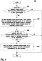
- FIG. 4 is a flow diagram of an example process 400 of transmit power control in accordance with an alternative embodiment.
- a WTRU determines whether a transmit power for any one of the antennas exceeds the maximum allowed power (402). If a transmit power for any antenna does not exceed the maximum allowed power, no power scaling may be performed. If a transmit power for any one of the antennas exceeds the maximum allowed power, the WTRU reduces a gain factor for a data channel, (e.g., E-DPDCHs), until the minimum configured value on the antenna(s) for which the maximum transmit power is exceeded such that the transmit power becomes below the maximum allowed power (404).
- This power scaling may be performed equally on both antennas in which case the beam pattern is maintained. Alternatively, this power scaling may be performed independently on each antenna, in which case some beam distortion may result.
- the data channel on one of the antennas may reach the minimum power before the data channel on the other antenna.
- the additional scaling in step 408 after the threshold test may be applied on the resulting signal of both antennas as is (that is with potentially unequal scaling of the data channels).
- the WTRU may first apply additional scaling to force the maximum reduction on the data channels of both antennas and then apply further power scaling on the result at step 408.
- Embodiments for transmit power control for multiple E-DCH codewords spatial multiplexing are disclosed hereafter.
- one power control loop may be established for each E-DCH codeword.
- a WTRU transmits two pilot channels (DPCCH1 and DPCCH2), and receive a separate transmit power control (TPC) command for each E-DCH codeword, and conventional power control may be applied to each DPCCH independently. This provides one relative power reference for each stream.
- Figure 5 shows an example transmitter 500 for dual E-DCH codeword spatial multiplexing in accordance with one embodiment.
- no DPDCH is transmitted when the WTRU is configured in UL MIMO mode
- two E-DPDCHs in different E-DPDCH streams share the same channelization code
- two E-DPCCHs share the same channelization code
- two DPCCHs share the same channelization code
- the pilots in the two DPCCHs are orthogonal to each other.
- this assumption is just for illustration purpose, and any configuration may be applied, (e.g., DPDCH may be simultaneously transmitted, and different channelization codes may be utilized for any of the channels).
- Figure 5 shows that the DPCCHs are not pre-coded, but as an alternative, the DPCCHs or any other control channels may also be precoded.
- w w 1 w 2 w 3 w 4
- the superscript is the index of the E-DCH codeword or the physical antenna.
- the transmitter 500 (i.e., WTRU), comprises channelization blocks 502, gain control blocks 504, I/Q mapping blocks 506, channel combiners 508, a precoding block, scrambling blocks, and antennas.
- Two E-DCH codewords (i.e., two E-DCH transport blocks), may be transmitted simultaneously.
- Each E-DCH codeword may be mapped to one or more than one E-DPDCH, and an E-DPCCH is transmitted along with each E-DCH codeword.
- Each channel (i.e., E-DPDCH, E-DPCCH, DPCCH, HS-DPCCH), is spread with a corresponding channelization code by a channelization block 502, and multiplied with a corresponding gain factor by a gain control block 504, and mapped to either an I channel or a Q channel by the I/Q mapping block 506.
- the E-DPDCHs and the E-DPCCH for each E-DCH codeword are combined by the channel combiner 508, respectively, and multiplied with precoding weights by the precoding block 510 to be distributed to each antenna.
- the DPCCH, the HS-DPCCH, and the precoded E-DCH channels are combined by the channel combiner 512 for each antenna.
- the channel combined signals are multiplied with a scrambling code by the scrambling block 514, and then transmitted via the antennas 516.
- a WTRU may calculate the E-DPDCH/DPCCH power offset, (i.e., E-DPDCH power offset to the power reference channel), for each stream independently.
- the WTRU calculates a temporary variable ⁇ ed,i,harq .
- Equations (44) and (45) may also be employed in the E-TFC restriction procedure to determine the set of supported E-TFCs.
- ⁇ mimo is an additional power offset factor introduced to take into account the additional required received power due to the MIMO or dual-stream transmission.
- ⁇ mimo compensates for the additional intra-WTRU interference caused by the additional MIMO stream at the Node-B receiver. Different Node-B receiver structure may require different level of compensation and thus ⁇ mimo may be signaled to the WTRU by a higher layer. ⁇ mimo may take a different value for each stream.
- the value of ⁇ mimo may depend on the MIMO operation mode: spatial-multiplexing or transmit diversity/beamforming.
- the WTRU may be configured with 2 values of ⁇ mimo, and one value may be used when two streams are transmitted and the other value may be used when a single stream is transmitted.
- the WTRU may determine, (e.g., based on Node-B signaling, channel state information, available headroom, etc.), how many streams can be transmitted before the E-TFC restriction, and calculate the set of supported E-TFCs and the power required for the chosen transport block (TB) size using the appropriate value of ⁇ mimo.
- the parameter ⁇ mimo may be combined in one of the variables in equations (44) and (45).
- the additional MIMO power offset may be absorbed in the HARQ power offset ( ⁇ harq ).
- the WTRU may be configured with two sets of HARQ power offsets: one set for dual-stream transmissions and another set for single-stream transmission.
- the additional MIMO power offset may be absorbed in the reference gain factors ( ⁇ ed,ref ). In that case, the WTRU may be configured with two sets of reference gain factors: one set for dual-stream transmissions and another set for single-stream transmission.
- the value of ⁇ mimo may depend on static parameters and/or dynamic parameters.
- the static parameters are in general related to the transmitter and receiver structures, including the receiver type at the Node-B, whether or not the DPCCH is precoded, whether or not the E-DPCCH is precoded, or the like. These static parameters may be taken into consideration in the value ⁇ mimo, which may be signaled by the network.
- Dynamic parameters may include the MIMO operating mode, (e.g., spatial-multiplexing vs. transmit diversity/beamforming), and the quality of service (QoS) of each stream, which may change on a TTI basis.
- the HARQ profile may be considered as a parameter for QoS.
- the ⁇ mimo for one stream may depend on the TB size (or equivalently power) on that E-DCH stream or alternatively the TB size (or equivalently power) of the other E-DCH stream.
- an additional MIMO power offset may be specified for all transport block sizes.
- a reduced set of additional MIMO power offsets may be used. This reduced set of additional MIMO power offsets may be designed to specify the additional MIMO power offset for a range of TB size.
- a WTRU may receive a list of transport block size, (or indices, i.e., E-TFCI), and associated additional MIMO power offset from the network and construct a table with the range and associated additional MIMO power offset, as shown in Table 1.
- the ⁇ mimo value may depend on the pair of TB sizes transmitted (one TB size per stream).
- the ratio of inter-stream interference depends to some extent on the relative power between each stream.
- a large transport block may interfere a small transport block relatively more than it would on a large transport block.
- the additional MIMO power offset value may depend on the power offset difference between the two E-DCH streams. Assuming, without loss of generality, that the first E-DCH stream is transmitted at a higher power than a second E-DCH stream. Let ⁇ P E-DCH be the power difference (in dB) between the power of the first E-DCH and the power of the second E-DCH.
- the power of the first E-DCH is defined as the total power of all E-DPDCHs associated with the first E-DCH stream and may also include the power of the associated E-DPCCH.
- the power of the second E-DCH is defined as the total power of all E-DPDCHs associated with the second E-DCH stream and may also include the power of the associated E-DPCCH.
- the WTRU may calculate values of additional MIMO power offsets ⁇ mimo1 and ⁇ mimo2 to apply to the first and second E-DCH streams, respectively based on the calculated value of ⁇ P E-DCH .
- the WTRU uses the values to determine the required additional MIMO power offset for each E-TFC pair. In E-TFC restriction, the WTRU may also calculate the required power for every E-TFC pair based on Table 2.
- Table 2 ⁇ P E-DCH range (dB) ⁇ mimo 1 ⁇ mimo 2 - ⁇ 1 N/A 0 0.5 1 1 - 3 0 2 3 - 6 0 3 6 - more 0 5
- ⁇ ed,k,reduced ⁇ ed,m, min on both streams
- equal scaling of all channels on both streams may be applied.
- ⁇ ed,k ,min may be configurable per stream.
- the WTRU may reduce the power of the E-DPDCH on a predetermined stream first.
- the predetermined stream may be the secondary stream. If the WTRU is still power-limited after the power scaling on the predetermined stream, then the WTRU may further reduce the power of the E-DPDCH on the other stream. If the WTRU is still power-limited after power scaling on the other stream, the additional scaling may be applied equally on both streams.
- the primary stream may be defined as the data stream that is transmitted over the preferred precoding weights signaled by the network and the secondary data stream may be defined as the other data stream transmitted over the precoding weights orthogonal to that used by the primary stream.
- Embodiments for sending UL transmit power control (TPC) commands for both E-DCH streams on a single DL DPCCH or fractional dedicated physical channel (F-DPCH) are disclosed.
- the network sends a TPC command for each E-DCH stream so that the WTRU receives two TPC commands for the two E-DCH streams on the downlink.
- the TPC commands for two E-DCH streams of a WTRU may be time-multiplexed on an F-DPCH.
- Figure 6 shows a conventional F-DPCH structure.
- two TPC bits per TPC command may be transmitted in each slot of the F-DPCH, so that up to 10 WTRUs are supported by a single F-DPCH.
- FIG. 7 shows an example TPC command transmission on an F-DPCH in accordance with this embodiment.
- TPC11 and TPC12 are the TPC command bits for stream 1 and stream 2, respectively, for the WTRU.
- N TPC 2
- up to five WTRUs configured for dual stream transmissions may be supported by one F-DPCH.
- One TPC bits field is transmitted to a WTRU that is not configured for dual stream transmissions.
- the TPC commands for the two E-DCH streams may or may not be adjacent in time on the F-DPCH.
- a new TPC bit pattern may be defined to combine the transmit power control commands for two power control loops, such that N TPC bits per TPC command indicate the TPC commands for two data streams.
- the gain of the F-DPCH field for the TPC command may be increased to support the additional information required.
- Table 3 shows conventional F-DPCH slot format 0, and example slot formats for the F-DPCH that may support more than 2 TPC bits per slot.
- slot format 0A and 0C support 4 TPC bits per slot and slot format 0B and 0D support 8 TPC bits per slot.
- Slot format 0 is the conventional F-DPCH slot format. Different F-DPCH slot formats may also be derived.
- Stream 1 and Stream 2 columns in Table 4 correspond to the TPC command interpretation for the first and second stream (or equivalently the first and second DPCCH), respectively.
- the TPC command for the WTRU is interpreted according to Table 4.
- the new TPC bit pattern for dual streams may be defined to maintain the backward compatibility.
- the TPC information for the first stream is the same as for the signal stream case.
- a new F-DPCH format with a smaller spreading factor may be introduced to send more information bits.
- a problem may occur regarding how to generate or combine a TPC command when a WTRU switches between a single power control loop and a dual power control loop.
- the WTRU may choose to transmit with one stream/codeword although the network signals the WTRU the current UL channel condition supports dual stream transmission. Consequently, one UL power control loop is sufficient for a single stream transmission while during the transition from the two power control loop to the single power control loop the WTRU may receive two TPC commands and combine the two TPC commands to derive a single TPC command to apply to the single stream transmission. This may be relevant, for instance, when the number of transmitted streams is dynamic but vary relatively slowly.
- the WTRU may combine the two TPC commands for the two streams as follows.
- the WTRU may generate the derived TPC command (TPC_cmd) of '1' if the hard decision on the value of both TPC commands are '1', otherwise, generate the derived TPC command (TPC_cmd) of '-1'.
- the network may transmit the TPC command for the single stream over the two configured TPC fields.
- the conventional F-DPCH format does not need to be reconfigured.
- the WTRU receives both TPC fields and make a decision on the final TPC command based on the information it receives from both TPC fields.
- the DPCCH power for the second DPCCH may be adjusted at each slot based on the power of the first DPCCH and the configured gain offset a.
- a transmitter may implement single codeword spatial multiplexing, wherein a single E-DCH codeword is transmitted via two transmit antennas.
- Figure 8 shows an example transmitter 800 for single codeword spatial multiplexing in accordance with one embodiment.
- no DPDCH is transmitted when the WTRU UL is configured in MIMO mode, two DPCCHs share the same channelization code, and the pilots in the two DPCCHs are orthogonal to each other.
- this assumption is just for illustration purpose, and any configuration may be applied, (e.g., DPDCH may be simultaneously transmitted, and different channelization codes may be utilized for any of the channels).
- Figure 8 shows that the DPCCHs are not pre-coded, but as an alternative, the DPCCHs or any other control channels may also be precoded.
- One E-DPCCH is transmitted since there is one E-DCH stream.
- the transmitter 800 (i.e., WTRU), comprises channelization blocks 802, gain control blocks 804, I/Q mapping blocks 806, channel combiners 808, 814, a demultiplexer 810, a precoding block 812, scrambling blocks 816, and antennas 818.
- One E-DCH codeword (i.e., one E-DCH transport block), is mapped to one or more than one E-DPDCH.
- Each channel (i.e., E-DPDCH, E-DPCCH, DPCCH, HS-DPCCH), is spread with a corresponding channelization code by a channelization block 802, and multiplied with a corresponding gain factor by a gain control block 804, and mapped to either an I channel or a Q channel by the I/Q mapping block 806.
- the E-DPDCHs are combined by the channel combiner 808, and demultiplexed to two streams by the demultiplexer 810.
- the two streams are multiplexed with precoding weights by the precoding block 812 to be distributed to each antenna.
- the DPCCH, the HS-DPCCH, the E-DPCCH, and the precoded E-DPDCHs are combined by the channel combiner 814 for each antenna.
- the channel combined signals are multiplied with a scrambling code by the scrambling block 816, and then transmitted via the antennas 818.
- the DPCCH and/or the E-DPCCH may also be precoded.
- the temporary variable ⁇ ed,i,harq calculation may follow the same as the equations (44) and (45), except the value of ⁇ mimo may not depend on the relative power between two transport blocks as only one transport block is transmitted.
- FIG. 9 shows an example transmitter 900 for implementing the pseudo spatial multiplexing scheme in accordance with one embodiment.
- the transmission scheme in Figure 9 is not a classical MIMO scheme and there is no need for multiple receive antennas at the base station as the streams can be separated by using the scrambling code.
- the Node-B receiver may simply treat each WTRU transmit antenna as a virtual user or WTRU. It is noted that multiple receive antennas at the base station with an interference cancellation receiver would provide improved performance for this case.
- two independent power control loop may be used, one for each virtual user/WTRU.
- the transmitter 900 (i.e., WTRU), comprises channelization blocks 902, gain control blocks 904, I/Q mapping blocks 906, channel combiners 908, 910, scrambling blocks 912, and antennas 914.
- Two E-DCH codewords (i.e., two E-DCH transport blocks), may be transmitted simultaneously.
- Each E-DCH codeword may be mapped to one or more than one E-DPDCH, and an E-DPCCH is transmitted along with each E-DCH codeword.
- Each channel (i.e., E-DPDCH, E-DPCCH, DPCCH, HS-DPCCH), is spread with a corresponding channelization code by a channelization block 902, and multiplied with a corresponding gain factor by a gain control block 904, and mapped to either an I channel or a Q channel by the I/Q mapping block 906.
- the channels are combined by the combiners 908, 910 for each antenna.
- the channel combined signals are multiplied with a different scrambling code by the scrambling block 912, and then transmitted via the antennas 914.
- the additional MIMO power offset may be included to increase the power of the data channel in accordance with equations (44) and (45).
- a power scaling in accordance with any embodiment disclosed above may be implemented.
- ROM read only memory
- RAM random access memory
- register cache memory
- semiconductor memory devices magnetic media such as internal hard disks and removable disks, magneto-optical media, and optical media such as CD-ROM disks, and digital versatile disks (DVDs).
- a processor in association with software may be used to implement a radio frequency transceiver for use in a WTRU, UE, terminal, base station, RNC, or any host computer.
Landscapes
- Engineering & Computer Science (AREA)
- Computer Networks & Wireless Communication (AREA)
- Signal Processing (AREA)
- Mobile Radio Communication Systems (AREA)
- Radio Transmission System (AREA)
- Transmitters (AREA)
Applications Claiming Priority (4)
| Application Number | Priority Date | Filing Date | Title |
|---|---|---|---|
| US24799509P | 2009-10-02 | 2009-10-02 | |
| US24803409P | 2009-10-02 | 2009-10-02 | |
| EP10765544A EP2484163A2 (en) | 2009-10-02 | 2010-10-01 | Method and apparatus for transmit power control for multiple antenna transmissions in the uplink |
| PCT/US2010/051185 WO2011041719A2 (en) | 2009-10-02 | 2010-10-01 | Method and apparatus for transmit power control for multiple antenna transmissions in the uplink |
Related Parent Applications (1)
| Application Number | Title | Priority Date | Filing Date |
|---|---|---|---|
| EP10765544A Division EP2484163A2 (en) | 2009-10-02 | 2010-10-01 | Method and apparatus for transmit power control for multiple antenna transmissions in the uplink |
Publications (1)
| Publication Number | Publication Date |
|---|---|
| EP3410789A1 true EP3410789A1 (en) | 2018-12-05 |
Family
ID=43533278
Family Applications (2)
| Application Number | Title | Priority Date | Filing Date |
|---|---|---|---|
| EP10765544A Withdrawn EP2484163A2 (en) | 2009-10-02 | 2010-10-01 | Method and apparatus for transmit power control for multiple antenna transmissions in the uplink |
| EP18173890.7A Pending EP3410789A1 (en) | 2009-10-02 | 2010-10-01 | Method and apparatus for transmit power control for multiple antenna transmissions in the uplink |
Family Applications Before (1)
| Application Number | Title | Priority Date | Filing Date |
|---|---|---|---|
| EP10765544A Withdrawn EP2484163A2 (en) | 2009-10-02 | 2010-10-01 | Method and apparatus for transmit power control for multiple antenna transmissions in the uplink |
Country Status (8)
| Country | Link |
|---|---|
| US (3) | US9031600B2 (ja) |
| EP (2) | EP2484163A2 (ja) |
| JP (5) | JP5597715B2 (ja) |
| KR (1) | KR101700471B1 (ja) |
| CN (2) | CN104270808B (ja) |
| AU (2) | AU2010300408B2 (ja) |
| TW (1) | TWI519189B (ja) |
| WO (1) | WO2011041719A2 (ja) |
Families Citing this family (90)
| Publication number | Priority date | Publication date | Assignee | Title |
|---|---|---|---|---|
| KR101281213B1 (ko) | 2003-09-26 | 2013-07-02 | 인터디지탈 테크날러지 코포레이션 | 무선 통신 전송 파워용 이득 팩터들의 판정을 위한 장치 및 방법 |
| US9312929B2 (en) | 2004-04-02 | 2016-04-12 | Rearden, Llc | System and methods to compensate for Doppler effects in multi-user (MU) multiple antenna systems (MAS) |
| US11394436B2 (en) | 2004-04-02 | 2022-07-19 | Rearden, Llc | System and method for distributed antenna wireless communications |
| US10749582B2 (en) | 2004-04-02 | 2020-08-18 | Rearden, Llc | Systems and methods to coordinate transmissions in distributed wireless systems via user clustering |
| US11309943B2 (en) | 2004-04-02 | 2022-04-19 | Rearden, Llc | System and methods for planned evolution and obsolescence of multiuser spectrum |
| US8542763B2 (en) | 2004-04-02 | 2013-09-24 | Rearden, Llc | Systems and methods to coordinate transmissions in distributed wireless systems via user clustering |
| US11451275B2 (en) | 2004-04-02 | 2022-09-20 | Rearden, Llc | System and method for distributed antenna wireless communications |
| US8654815B1 (en) | 2004-04-02 | 2014-02-18 | Rearden, Llc | System and method for distributed antenna wireless communications |
| US10985811B2 (en) | 2004-04-02 | 2021-04-20 | Rearden, Llc | System and method for distributed antenna wireless communications |
| US10886979B2 (en) | 2004-04-02 | 2021-01-05 | Rearden, Llc | System and method for link adaptation in DIDO multicarrier systems |
| US10200094B2 (en) | 2004-04-02 | 2019-02-05 | Rearden, Llc | Interference management, handoff, power control and link adaptation in distributed-input distributed-output (DIDO) communication systems |
| US10425134B2 (en) | 2004-04-02 | 2019-09-24 | Rearden, Llc | System and methods for planned evolution and obsolescence of multiuser spectrum |
| US10277290B2 (en) | 2004-04-02 | 2019-04-30 | Rearden, Llc | Systems and methods to exploit areas of coherence in wireless systems |
| US9685997B2 (en) | 2007-08-20 | 2017-06-20 | Rearden, Llc | Systems and methods to enhance spatial diversity in distributed-input distributed-output wireless systems |
| EP2289273A4 (en) * | 2008-06-19 | 2013-11-13 | Ericsson Telefon Ab L M | PREDICTION OF BIT RATE |
| AU2010300408B2 (en) | 2009-10-02 | 2014-04-17 | Interdigital Patent Holdings, Inc. | Method and apparatus for transmit power control for multiple antenna transmissions in the uplink |
| US9059760B2 (en) * | 2010-02-05 | 2015-06-16 | Qualcomm Incorporated | Apparatus and method for enabling uplink beamforming transit diversity |
| US9144040B2 (en) * | 2010-04-01 | 2015-09-22 | Futurewei Technologies, Inc. | System and method for uplink multi-antenna power control in a communications system |
| US9197296B2 (en) * | 2010-04-05 | 2015-11-24 | Qualcomm Incorporated | Method and apparatus for maximum ratio transmission mobile transmit diversity system |
| WO2011127358A1 (en) * | 2010-04-09 | 2011-10-13 | Interdigital Patent Holdings Inc. | Method and apparatus for power control for closed loop transmit diversity and mimo in uplink |
| US8838161B2 (en) * | 2010-06-16 | 2014-09-16 | Samsung Electronics Co., Ltd | Uplink power control method for mobile communication system |
| WO2012044967A1 (en) | 2010-10-01 | 2012-04-05 | Interdigital Patent Holdings, Inc. | Method and apparatus for transmitting pilot on multiple antennas |
| US9007888B2 (en) | 2010-11-08 | 2015-04-14 | Qualcomm Incorporated | System and method for uplink multiple input multiple output transmission |
| US8953713B2 (en) | 2010-11-08 | 2015-02-10 | Qualcomm Incorporated | System and method for uplink multiple input multiple output transmission |
| US20120281642A1 (en) * | 2010-11-08 | 2012-11-08 | Qualcomm Incorporated | System and method for uplink multiple input multiple output transmission |
| US9380490B2 (en) | 2010-11-08 | 2016-06-28 | Qualcomm Incorporated | System and method for uplink multiple input multiple output transmission |
| US9516609B2 (en) | 2010-11-08 | 2016-12-06 | Qualcomm Incorporated | System and method for uplink multiple input multiple output transmission |
| US9084207B2 (en) | 2010-11-08 | 2015-07-14 | Qualcomm Incorporated | System and method for uplink multiple input multiple output transmission |
| US9055604B2 (en) | 2012-02-08 | 2015-06-09 | Qualcomm Incorporated | Method and apparatus for E-TFC selection for uplink MIMO communication |
| CN103283155B (zh) * | 2011-01-07 | 2017-12-08 | 交互数字专利控股公司 | 在wtru中实施的传输格式组合选择的方法以及wtru |
| US20120275403A1 (en) * | 2011-04-29 | 2012-11-01 | Interdigital Patent Holdings, Inc. | Transmission of e-dch control channel in mimo operations |
| CN102843759B (zh) | 2011-06-23 | 2016-03-02 | 华为技术有限公司 | 一种上行多入多出信道的功率控制方法和用户设备 |
| US9232482B2 (en) | 2011-07-01 | 2016-01-05 | QUALOCOMM Incorporated | Systems, methods and apparatus for managing multiple radio access bearer communications |
| US9167472B2 (en) | 2011-07-01 | 2015-10-20 | Qualcomm Incorporated | Methods and apparatus for enhanced UL RLC flow control for MRAB calls |
| US9357482B2 (en) * | 2011-07-13 | 2016-05-31 | Alcatel Lucent | Method and system for dynamic power control for base stations |
| US9591593B2 (en) * | 2011-07-22 | 2017-03-07 | Qualcomm Incorporated | Systems, methods and apparatus for radio uplink power control |
| US9930569B2 (en) | 2011-08-04 | 2018-03-27 | Qualcomm Incorporated | Systems, methods and apparatus for wireless condition based multiple radio access bearer communications |
| US8644875B2 (en) * | 2011-09-08 | 2014-02-04 | Nokia Corporation | Transmit power control in multi-radio apparatus |
| US9686046B2 (en) | 2011-09-13 | 2017-06-20 | Qualcomm Incorporated | Systems, methods and apparatus for wireless condition based multiple radio access bearer communications |
| EP3419188A1 (en) * | 2011-09-14 | 2018-12-26 | Rearden Mova, LLC | Systems and methods to exploit areas of coherence in wireless systems |
| EP2810390B1 (en) * | 2012-01-31 | 2018-12-26 | Telefonaktiebolaget LM Ericsson (publ) | Methods, network node, and user equipment for uplink multiple-input-multiple-output |
| US9137698B2 (en) * | 2012-02-24 | 2015-09-15 | Samsung Electronics Co., Ltd. | Beam management for wireless communication |
| CN102594521B (zh) * | 2012-03-16 | 2015-05-13 | 华为技术有限公司 | 控制信息的传输方法及系统、用户设备与基站 |
| US9467951B2 (en) * | 2012-06-29 | 2016-10-11 | Telefonaktiebolaget Lm Ericsson (Publ) | Uplink transmit power control |
| US9674801B2 (en) * | 2012-07-26 | 2017-06-06 | Huawei Technologies Co., Ltd. | UE power allocation according to scheduler utility metric for DL MU-MIMO and DL CoMP |
| WO2014070081A1 (en) * | 2012-11-02 | 2014-05-08 | Telefonaktiebolaget L M Ericsson (Publ) | Method and device of performing multi-radio access bearer power scaling |
| WO2014070068A1 (en) * | 2012-11-02 | 2014-05-08 | Telefonaktiebolaget L M Ericsson (Publ) | Methods and apparatuses for boosting channel transmission in a network |
| US11189917B2 (en) | 2014-04-16 | 2021-11-30 | Rearden, Llc | Systems and methods for distributing radioheads |
| US10194346B2 (en) | 2012-11-26 | 2019-01-29 | Rearden, Llc | Systems and methods for exploiting inter-cell multiplexing gain in wireless cellular systems via distributed input distributed output technology |
| US11050468B2 (en) | 2014-04-16 | 2021-06-29 | Rearden, Llc | Systems and methods for mitigating interference within actively used spectrum |
| US11190947B2 (en) | 2014-04-16 | 2021-11-30 | Rearden, Llc | Systems and methods for concurrent spectrum usage within actively used spectrum |
| US10164698B2 (en) | 2013-03-12 | 2018-12-25 | Rearden, Llc | Systems and methods for exploiting inter-cell multiplexing gain in wireless cellular systems via distributed input distributed output technology |
| US10488535B2 (en) | 2013-03-12 | 2019-11-26 | Rearden, Llc | Apparatus and method for capturing still images and video using diffraction coded imaging techniques |
| US9973246B2 (en) | 2013-03-12 | 2018-05-15 | Rearden, Llc | Systems and methods for exploiting inter-cell multiplexing gain in wireless cellular systems via distributed input distributed output technology |
| RU2767777C2 (ru) | 2013-03-15 | 2022-03-21 | Риарден, Ллк | Системы и способы радиочастотной калибровки с использованием принципа взаимности каналов в беспроводной связи с распределенным входом - распределенным выходом |
| CN104170338B (zh) * | 2013-03-22 | 2016-08-24 | 华为技术有限公司 | 功率控制方法及装置、系统 |
| WO2015012502A1 (en) * | 2013-07-26 | 2015-01-29 | Lg Electronics Inc. | Method for adjusting a transmission power |
| US9521655B2 (en) * | 2013-07-30 | 2016-12-13 | Qualcomm Incorporated | Method and apparatus for avoiding power scaling in uplink data transmission |
| KR102065696B1 (ko) * | 2013-08-01 | 2020-01-14 | 삼성전자주식회사 | 무선 통신 시스템에서 적응적 송신 전력 정규화를 위한 장치 및 방법 |
| US9456426B2 (en) * | 2013-12-06 | 2016-09-27 | Qualcomm Incorporated | Determining a gain factor for transmit power control in enhanced uplink |
| WO2015142275A2 (en) | 2014-03-21 | 2015-09-24 | Telefonaktiebolaget L M Ericsson (Publ) | Setting initial transmission power for a secondary carrier after a transmission gap |
| US11290162B2 (en) | 2014-04-16 | 2022-03-29 | Rearden, Llc | Systems and methods for mitigating interference within actively used spectrum |
| US20160028514A1 (en) * | 2014-07-25 | 2016-01-28 | Lsi Corporation | Configurable Transmitter Hardware Block and Methods |
| CN106575986B (zh) * | 2014-08-13 | 2021-02-12 | 诺基亚通信公司 | 调节用于基于特征值的波束形成的传输功率的方法 |
| US9730228B2 (en) * | 2014-08-29 | 2017-08-08 | Corning Optical Communications Wireless Ltd | Individualized gain control of remote uplink band paths in a remote unit in a distributed antenna system (DAS), based on combined uplink power level in the remote unit |
| WO2016067437A1 (ja) * | 2014-10-31 | 2016-05-06 | 株式会社日立製作所 | 通信システム |
| CN105993198B (zh) * | 2015-01-16 | 2019-07-12 | 华为技术有限公司 | 用户设备发射功率的控制方法及装置 |
| WO2017022108A1 (ja) * | 2015-08-05 | 2017-02-09 | 三菱電機株式会社 | 無線送信装置 |
| US10205491B2 (en) * | 2015-09-28 | 2019-02-12 | Futurewei Technologies, Inc. | System and method for large scale multiple input multiple output communications |
| US11212141B2 (en) * | 2016-01-07 | 2021-12-28 | Qualcomm Incorporated | Methods and apparatus for a data transmission scheme for Narrow-Band Internet of Things (NB-IoT) |
| KR102209642B1 (ko) | 2016-02-24 | 2021-01-29 | 노키아 솔루션스 앤드 네트웍스 오와이 | 업링크 송신 전력 제어 |
| WO2017182059A1 (en) * | 2016-04-19 | 2017-10-26 | Telefonaktiebolaget Lm Ericsson (Publ) | Power control and beamforming with a plurality of power amplifiers |
| JP2019145866A (ja) * | 2016-07-05 | 2019-08-29 | シャープ株式会社 | 基地局装置、端末装置および通信方法 |
| EP3497961A4 (en) * | 2016-08-10 | 2020-04-08 | Telefonaktiebolaget LM Ericsson (publ) | TECHNIQUE FOR TRANSMITTING DATA IN A RADIO ACCESS NETWORK |
| EP3313129B1 (en) * | 2016-10-21 | 2022-03-09 | ASUSTek Computer Inc. | Method and apparatus for power headroom report for beam operation in a wireless communication system |
| CN109526047B (zh) | 2016-12-29 | 2021-05-28 | 上海琦予通信科技服务中心 | 一种用于功率调整的ue、基站中的方法和装置 |
| US10368325B2 (en) * | 2017-02-03 | 2019-07-30 | Futurewei Technologies, Inc. | System and method for beam adaptation in a beam-based communications system |
| CN107094038B (zh) * | 2017-03-06 | 2020-07-24 | 上海华为技术有限公司 | 一种天线系统功率调整的方法、装置及系统 |
| US10425901B2 (en) * | 2017-06-26 | 2019-09-24 | Qualcomm Incorporated | Uplink transmit power control during random access procedures |
| CN109309520B (zh) | 2017-07-26 | 2023-04-14 | 三星电子株式会社 | 使用天线阵列的用于无线通信的方法和设备 |
| CN110945894B (zh) * | 2017-08-04 | 2023-06-16 | 株式会社Ntt都科摩 | 终端及通信方法 |
| US11160030B2 (en) * | 2017-11-03 | 2021-10-26 | Qualcomm Incorporated | Power control in directional beam environments |
| KR101894065B1 (ko) * | 2018-01-31 | 2018-09-04 | (주)베스트인포텍 | 사물인터넷 통신을 위한 저 전력 광역 네트워크 기반 대역폭 결정 방법 및 장치 |
| US20190394733A1 (en) * | 2018-06-20 | 2019-12-26 | Mediatek Inc. | Ul transmission utilizing full tx power at ue |
| US11076409B2 (en) * | 2018-07-30 | 2021-07-27 | Qualcomm Incorporated | Power allocation for subband precoding |
| US11765668B2 (en) * | 2018-09-28 | 2023-09-19 | Apple Inc. | LTE NR power control for EN-DC |
| US11166240B2 (en) | 2019-01-24 | 2021-11-02 | Parallel Wireless, Inc. | Power budget calculation using power headroom |
| US11979113B2 (en) | 2019-02-12 | 2024-05-07 | Telefonaktiebolaget Lm Ericsson (Publ) | Apparatus and a method in a wireless communications network |
| US11617139B2 (en) * | 2019-08-27 | 2023-03-28 | Qualcomm Incorporated | Power control for repeated uplink transmissions |
| US11621748B1 (en) * | 2021-11-18 | 2023-04-04 | First Rf Corporation | High-power transmit beamforming with impedance-mismatched antenna arrays |
Family Cites Families (59)
| Publication number | Priority date | Publication date | Assignee | Title |
|---|---|---|---|---|
| KR100735402B1 (ko) * | 2000-11-07 | 2007-07-04 | 삼성전자주식회사 | 비동기 이동통신시스템에서 하향 공유 채널에 사용하는 송신 형식 결합 지시기의 전송 장치 및 방법 |
| JP3806116B2 (ja) * | 2001-09-21 | 2006-08-09 | 株式会社エヌ・ティ・ティ・ドコモ | 移動パケット通信システムにおける送信電力制御方法及び無線制御装置 |
| US20030108013A1 (en) * | 2001-11-19 | 2003-06-12 | Samsung Electronics Co., Ltd. | Method and apparatus for uplink transmission power control in a CDMA communication system |
| US7020110B2 (en) * | 2002-01-08 | 2006-03-28 | Qualcomm Incorporated | Resource allocation for MIMO-OFDM communication systems |
| JP4005400B2 (ja) * | 2002-04-10 | 2007-11-07 | 富士通株式会社 | 送信フォーマット組み合わせ情報選択方法及び移動端末装置 |
| JP4130413B2 (ja) * | 2002-04-10 | 2008-08-06 | コーニンクレッカ フィリップス エレクトロニクス エヌ ヴィ | Arqを用いる通信システム |
| JP3574446B2 (ja) * | 2002-09-19 | 2004-10-06 | 松下電器産業株式会社 | 送信電力制御方法および基地局装置 |
| KR100900970B1 (ko) * | 2002-10-19 | 2009-06-08 | 삼성전자주식회사 | 기지국/이동국 다중안테나를 포함하는 이동통신장치 및 방법 |
| JP4095462B2 (ja) | 2003-02-10 | 2008-06-04 | 京セラ株式会社 | 無線装置および無線基地局 |
| EP1509012A2 (en) * | 2003-08-20 | 2005-02-23 | Samsung Electronics Co., Ltd. | Method and apparatus for scheduling uplink packet transmission in a mobile communication system |
| US7194286B2 (en) | 2003-09-30 | 2007-03-20 | Lucent Technologies Inc. | Method for optimizing the transmit signal in multiple antenna wireless links |
| DE102004003549B4 (de) * | 2004-01-23 | 2007-03-29 | Siemens Ag | Kommunikationssystem und Verfahren zum Verarbeiten einer von einem Mobilfunkendgerät eines Mobilfunk-Kommunikationsnetzes einem Nachrichtenfilter-Rechner zugeführten Anforderungs-Nachricht |
| EP1714404B3 (en) * | 2004-02-14 | 2014-07-23 | Samsung Electronics Co., Ltd. | Apparatus and method for allocating ovsf codes and i/q channels for reducing peak-to-average power ratio in transmitting data via enhanced up-link dedicated channels in wcdma systems |
| KR100640516B1 (ko) * | 2004-02-27 | 2006-10-30 | 삼성전자주식회사 | 직교주파수분할다중화 통신 시스템에서 채널품질 정보의전송방법 및 장치 |
| US7551589B2 (en) * | 2004-04-02 | 2009-06-23 | Lg Electronics Inc. | Frame structure of uplink control information transmission channel in MIMO communication system |
| JP2005347922A (ja) * | 2004-06-01 | 2005-12-15 | Nec Corp | 送信信号生成回路および無線基地局通信装置 |
| JP4299270B2 (ja) * | 2004-06-09 | 2009-07-22 | 三星電子株式会社 | 向上した上りリンクサービスを支援する移動通信システムにおけるデータ送信のための方法及び装置 |
| JP4711750B2 (ja) * | 2005-04-13 | 2011-06-29 | 株式会社エヌ・ティ・ティ・ドコモ | 移動通信システム、移動局及び基地局並びに通信制御方法 |
| JP4756897B2 (ja) * | 2005-04-18 | 2011-08-24 | 株式会社エヌ・ティ・ティ・ドコモ | 移動局及びフィードバック情報生成方法 |
| US7408895B2 (en) * | 2005-04-20 | 2008-08-05 | Interdigital Technology Corporation | Method and apparatus for scheduling transmissions via an enhanced dedicated channel |
| US20060262874A1 (en) * | 2005-05-17 | 2006-11-23 | Interdigital Technology Corporation | Method and apparatus for power control in a multiple antenna system |
| WO2006129661A1 (ja) * | 2005-06-01 | 2006-12-07 | Matsushita Electric Industrial Co., Ltd. | 送信装置、受信装置及び送信電力制御方法 |
| US7734262B2 (en) * | 2005-07-18 | 2010-06-08 | Rashid Ahmed Akbar Attar | Method and apparatus for reverse link throttling in a multi-carrier wireless communication system |
| EP3461213A1 (en) * | 2005-11-04 | 2019-03-27 | LG Electronics Inc. | Random access dimensioning methods and procedures for frequency division multiplexing access systems |
| US7729714B2 (en) * | 2005-12-20 | 2010-06-01 | Qualcomm Incorporated | Method and apparatus for reverse link transmit beam-forming |
| US7729715B2 (en) * | 2005-12-30 | 2010-06-01 | Motorola, Inc. | Method and apparatus for power reduction for E-TFC selection |
| KR101159606B1 (ko) * | 2006-07-06 | 2012-07-10 | 인터디지탈 테크날러지 코포레이션 | 전송될 수 있는 최고 페이로드로 스케줄링 그랜트 페이로드를 설정함으로써 향상된 업링크 트랜스포트 포맷 조합을 선택하는 무선 통신 방법 |
| KR100946930B1 (ko) * | 2006-07-31 | 2010-03-09 | 삼성전자주식회사 | 통신 시스템에서 송신 안테나 이득 제어 방법 및 장치 |
| WO2008024282A2 (en) * | 2006-08-21 | 2008-02-28 | Interdigital Technology Corporation | Method and apparatus for controlling arq and harq transmissions and retranmissions in a wireless communication system |
| CN100471085C (zh) * | 2006-08-22 | 2009-03-18 | 华为技术有限公司 | 上行物理信道的功率控制方法及装置 |
| US20080107198A1 (en) * | 2006-11-07 | 2008-05-08 | Innovative Sonic Limited | Method and apparatus for performing multi-input multi-output transmission in a wireless communications system |
| US9204403B2 (en) | 2006-12-21 | 2015-12-01 | Alcatel Lucent | Power overload control method useful with high speed downlink packet access |
| US8233932B2 (en) * | 2007-02-02 | 2012-07-31 | Qualcomm Incorporated | Method and apparatus for improving signaling reliability in wireless communications |
| US20100246520A1 (en) | 2007-11-26 | 2010-09-30 | Andreas Andersson | Outer Loop Power Control for E-DCH |
| KR101572880B1 (ko) | 2007-12-12 | 2015-11-30 | 엘지전자 주식회사 | 다중화율을 고려한 상향링크 전력제어 방법 |
| JP5165397B2 (ja) * | 2008-01-16 | 2013-03-21 | 株式会社エヌ・ティ・ティ・ドコモ | 無線基地局 |
| WO2009108088A1 (en) * | 2008-02-29 | 2009-09-03 | Telefonaktiebogalet Lm Ericsson (Publ) | Signalling gain factors in a communication network system |
| US8233559B2 (en) * | 2008-03-12 | 2012-07-31 | Lg Electronics Inc. | Method and apparatus for transmitting a pilot in multi-antenna system |
| US20090290559A1 (en) * | 2008-04-24 | 2009-11-26 | Interdigital Patent Holdings, Inc. | Method and apparatus for harq autonomous retransmissions |
| FR2930856B1 (fr) * | 2008-04-30 | 2010-06-18 | Commissariat Energie Atomique | Systeme de telecommunication multi-acces a strategie de retransmission de paquets adaptee |
| US20100074131A1 (en) * | 2008-09-22 | 2010-03-25 | Texas Instruments Incorporated | Power offset for cqi reporting |
| AU2009307781B2 (en) * | 2008-10-20 | 2014-04-10 | Interdigital Patent Holdings, Inc | Carrier aggregation |
| US8245092B2 (en) * | 2008-11-03 | 2012-08-14 | Apple Inc. | Method for efficient control signaling of two codeword to one codeword transmission |
| US8149776B2 (en) * | 2009-05-12 | 2012-04-03 | Nokia Corporation | Method, apparatus and computer program for user equipment access channel procedures |
| US8401585B2 (en) * | 2009-09-03 | 2013-03-19 | Telefonaktiebolaget L M Ericsson (Publ) | Method and apparatus for uplink power control in a wireless communication network |
| AU2010300408B2 (en) * | 2009-10-02 | 2014-04-17 | Interdigital Patent Holdings, Inc. | Method and apparatus for transmit power control for multiple antenna transmissions in the uplink |
| US8913535B2 (en) * | 2010-10-01 | 2014-12-16 | Interdigital Patent Holdings, Inc. | Systems and methods for uplink feedback for high-speed downlink packet access (HSPDA) |
| KR20120047204A (ko) * | 2010-11-03 | 2012-05-11 | 삼성전자주식회사 | 시분할 이중화 시스템에서의 수신 확인 정보 생성 및 전력 제어를 위한 방법 및 장치 |
| US20120281544A1 (en) * | 2010-11-05 | 2012-11-08 | Interdigital Patent Holdings, Inc. | Mobility For Multipoint Operations |
| EP2663136B1 (en) * | 2011-01-07 | 2017-10-18 | Panasonic Intellectual Property Corporation of America | Wireless communication terminal and power control method |
| WO2012109623A1 (en) * | 2011-02-11 | 2012-08-16 | Interdigital Patent Holdings, Inc. | Multi- carrier hsdpa control metho and apparatus |
| TW201234793A (en) * | 2011-02-11 | 2012-08-16 | Interdigital Patent Holdings | Method and apparatus for closed loop transmit diversity transmission initial access |
| JP5908504B2 (ja) * | 2011-03-08 | 2016-04-26 | パナソニック インテレクチュアル プロパティ コーポレーション オブ アメリカPanasonic Intellectual Property Corporation of America | 複数のコンポーネント・キャリアに関する伝搬遅延差レポート |
| US20120275403A1 (en) * | 2011-04-29 | 2012-11-01 | Interdigital Patent Holdings, Inc. | Transmission of e-dch control channel in mimo operations |
| CN103733550B (zh) * | 2011-07-29 | 2016-08-17 | Lg电子株式会社 | 控制上行链路传输功率的终端设备和方法 |
| US9253753B2 (en) * | 2012-04-24 | 2016-02-02 | Zetta Research And Development Llc-Forc Series | Vehicle-to-vehicle safety transceiver using time slots |
| WO2014058257A1 (en) * | 2012-10-12 | 2014-04-17 | Kt Corporation | Controlling uplink power |
| JP2017085188A (ja) * | 2014-03-13 | 2017-05-18 | シャープ株式会社 | 端末装置、基地局装置および通信方法 |
| JP6592448B2 (ja) * | 2014-10-17 | 2019-10-16 | シャープ株式会社 | 端末装置、通信方法、および、集積回路 |
-
2010
- 2010-10-01 AU AU2010300408A patent/AU2010300408B2/en active Active
- 2010-10-01 US US12/896,668 patent/US9031600B2/en active Active
- 2010-10-01 EP EP10765544A patent/EP2484163A2/en not_active Withdrawn
- 2010-10-01 WO PCT/US2010/051185 patent/WO2011041719A2/en active Application Filing
- 2010-10-01 JP JP2012532367A patent/JP5597715B2/ja active Active
- 2010-10-01 CN CN201410522246.5A patent/CN104270808B/zh active Active
- 2010-10-01 KR KR1020127011266A patent/KR101700471B1/ko active IP Right Grant
- 2010-10-01 CN CN2010800444322A patent/CN102577542A/zh active Pending
- 2010-10-01 EP EP18173890.7A patent/EP3410789A1/en active Pending
- 2010-10-04 TW TW099133722A patent/TWI519189B/zh active
-
2014
- 2014-07-16 AU AU2014204450A patent/AU2014204450B2/en active Active
- 2014-08-11 JP JP2014163709A patent/JP5879404B2/ja active Active
-
2015
- 2015-05-11 US US14/708,850 patent/US9867147B2/en active Active
-
2016
- 2016-02-01 JP JP2016017140A patent/JP6220907B2/ja active Active
-
2017
- 2017-10-02 JP JP2017193073A patent/JP6832825B2/ja active Active
-
2018
- 2018-01-08 US US15/864,607 patent/US10602458B2/en active Active
-
2019
- 2019-11-25 JP JP2019212349A patent/JP2020025365A/ja active Pending
Non-Patent Citations (3)
| Title |
|---|
| "3rd Generation Partnership Project; Technical Specification Group Radio Access Network; Physical layer procedures (FDD) (Release 9)", 3GPP STANDARD; 3GPP TS 25.214, 3RD GENERATION PARTNERSHIP PROJECT (3GPP), MOBILE COMPETENCE CENTRE ; 650, ROUTE DES LUCIOLES ; F-06921 SOPHIA-ANTIPOLIS CEDEX ; FRANCE, no. V9.0.0, 1 September 2009 (2009-09-01), pages 1 - 95, XP050366893 * |
| "3rd Generation Partnership Project; Technical Specification Group Radio Access Network; User Equipment (UE) radio transmission and reception (FDD) (Release 9)", 3GPP STANDARD; 3GPP TS 25.101, 3RD GENERATION PARTNERSHIP PROJECT (3GPP), MOBILE COMPETENCE CENTRE ; 650, ROUTE DES LUCIOLES ; F-06921 SOPHIA-ANTIPOLIS CEDEX ; FRANCE, no. V9.1.0, 1 September 2009 (2009-09-01), pages 1 - 218, XP050365882 * |
| MAGNOLIA BROADBAND: "Analysis of UE Transmit Power due to Uplink Beamforming Transmit Diversity in HSPA", 3GPP DRAFT; R4-091764, 3RD GENERATION PARTNERSHIP PROJECT (3GPP), MOBILE COMPETENCE CENTRE ; 650, ROUTE DES LUCIOLES ; F-06921 SOPHIA-ANTIPOLIS CEDEX ; FRANCE, no. San Francisco; 20090504, 4 May 2009 (2009-05-04), XP050342502 * |
Also Published As
| Publication number | Publication date |
|---|---|
| JP2020025365A (ja) | 2020-02-13 |
| AU2014204450A1 (en) | 2014-07-31 |
| KR20120107937A (ko) | 2012-10-04 |
| US20110105174A1 (en) | 2011-05-05 |
| CN102577542A (zh) | 2012-07-11 |
| CN104270808B (zh) | 2018-02-16 |
| JP5597715B2 (ja) | 2014-10-01 |
| WO2011041719A3 (en) | 2011-07-21 |
| US20150245304A1 (en) | 2015-08-27 |
| WO2011041719A2 (en) | 2011-04-07 |
| US9867147B2 (en) | 2018-01-09 |
| TWI519189B (zh) | 2016-01-21 |
| JP2016119690A (ja) | 2016-06-30 |
| JP2015008501A (ja) | 2015-01-15 |
| AU2010300408B2 (en) | 2014-04-17 |
| US10602458B2 (en) | 2020-03-24 |
| JP5879404B2 (ja) | 2016-03-08 |
| AU2010300408A1 (en) | 2012-04-26 |
| JP2013507071A (ja) | 2013-02-28 |
| US20180132195A1 (en) | 2018-05-10 |
| JP6832825B2 (ja) | 2021-02-24 |
| TW201119451A (en) | 2011-06-01 |
| AU2014204450B2 (en) | 2016-05-12 |
| KR101700471B1 (ko) | 2017-01-26 |
| US9031600B2 (en) | 2015-05-12 |
| JP2018042249A (ja) | 2018-03-15 |
| CN104270808A (zh) | 2015-01-07 |
| JP6220907B2 (ja) | 2017-10-25 |
| EP2484163A2 (en) | 2012-08-08 |
Similar Documents
| Publication | Publication Date | Title |
|---|---|---|
| US10602458B2 (en) | Uplink transmit diversity in a wireless network | |
| US9826490B2 (en) | Power control for closed loop transmit diversity and MIMO in uplink | |
| TWI596917B (zh) | 具多天線裝置之功率控制 |
Legal Events
| Date | Code | Title | Description |
|---|---|---|---|
| PUAI | Public reference made under article 153(3) epc to a published international application that has entered the european phase |
Free format text: ORIGINAL CODE: 0009012 |
|
| STAA | Information on the status of an ep patent application or granted ep patent |
Free format text: STATUS: THE APPLICATION HAS BEEN PUBLISHED |
|
| AC | Divisional application: reference to earlier application |
Ref document number: 2484163 Country of ref document: EP Kind code of ref document: P |
|
| AK | Designated contracting states |
Kind code of ref document: A1 Designated state(s): AL AT BE BG CH CY CZ DE DK EE ES FI FR GB GR HR HU IE IS IT LI LT LU LV MC MK MT NL NO PL PT RO RS SE SI SK SM TR |
|
| STAA | Information on the status of an ep patent application or granted ep patent |
Free format text: STATUS: REQUEST FOR EXAMINATION WAS MADE |
|
| 17P | Request for examination filed |
Effective date: 20190604 |
|
| RBV | Designated contracting states (corrected) |
Designated state(s): AL AT BE BG CH CY CZ DE DK EE ES FI FR GB GR HR HU IE IS IT LI LT LU LV MC MK MT NL NO PL PT RO RS SE SI SK SM TR |
|
| STAA | Information on the status of an ep patent application or granted ep patent |
Free format text: STATUS: EXAMINATION IS IN PROGRESS |
|
| 17Q | First examination report despatched |
Effective date: 20191001 |
|
| STAA | Information on the status of an ep patent application or granted ep patent |
Free format text: STATUS: EXAMINATION IS IN PROGRESS |
|
| STAA | Information on the status of an ep patent application or granted ep patent |
Free format text: STATUS: EXAMINATION IS IN PROGRESS |
|
| RAP3 | Party data changed (applicant data changed or rights of an application transferred) |
Owner name: INTERDIGITAL PATENT HOLDINGS, INC. |